Abstract
The low specific surface area and insufficient exposure of active sites are usually the key reasons for the poor oxygen reduction reaction of catalysts. Here, we update a new method, using NaCl as a template, egg white as a carbon source and nitrogen source, adding FeCl3 as an iron source, and adopting a two-step pyrolysis method to synthesize a sponge-like porous Fe-N-C catalyst. This kind of three-dimensional sponge-like catalyst exhibits more defective structures, so it shows an excellent electrochemical performance with a half-wave potential of 0.73 V and onset potential of 0.88 V. Additionally, the catalyst has amazing stability, which proves that it is a promising candidate for green energy devices. Our research provides an innovative method to synthesize high-performance Fe-N-C catalysts using low-cost common biomaterials.
1. Introduction
In recent years, fuel cells with high energy density have drawn significant interest in new-generation portable energy storage devices due to their low costs, abundant material, and environmental friendliness [1,2,3]. However, the development of fuel cells is hindered by the sluggish dynamic behavior and multiple electron transfer processes of the cathode oxygen reduction reaction (ORR) [4]. At present, most of the ORR catalysts are still precious-metal-based (such as Pt, Ir, Pt, and their alloys) [5,6]. The high cost, limited reserves, and poor stability of these precious metal-based catalysts severely impede their large-scale commercial application. Hence, developing low-cost and high-efficient catalysts for ORR is of paramount importance for fuel cells currently. Over the past several years, considerable efforts have been devoted to developing carbon–based non-precious-metal catalysts (NPMCs) with excellent ORR performance [7,8,9,10,11].
Since Jasinski et al., reported that cobalt phthalocyanine with the ability to reduce oxygen plays an important role in fuel cells in 1964 [12], more metal macrocyclic compounds based on bioactive oxidases have been discovered with oxygen reduction activity. With the fast development of non-precious-metal electrocatalysts, fuel cell catalysts have been gradually converted from precious metals to non-precious metals. Transition metal oxides, transition metal non-oxide compounds, and metal/nitrogen/carbon hybrid materials are extensively reported as promising ORR electrocatalysts [13]. With global warming and environmental pollution, more and more “green resources” derived from biomasses with fine structures have been recycled and utilized for innovative material production in a more environmentally friendly way. Zhang et al., reported N-doped carbon matrix-supported Co Single Atom Catalysts coordinated with pyridinic N, graphitic N, and pyrrolic N, respectively. Additionally, they found that the graphitic N-doped catalyst showed the best ORR performance among them, confirming the boosting effects of the graphitic N doping [14]. Some biomass-containing proteins, including fish scale waste [9], shrimp shell [15], and hemin [8], were successfully fabricated to the N-doped carbon catalysts with electrocatalytic activity and durability.
Egg white is a high-protein biomass resource, providing rich carbon, nitrogen, and oxygen sources, which could be a potential candidate for fuel cells. Some studies have shown that the synthesis of ORR catalysts with egg white achieves desirable catalytic performance [16,17,18]. At the same time, we used sodium chloride as a template to control the morphology and structure of pyrolysis products, helping to form a porous sponge-like three-dimensional structure, thus exposing more active sites.
In this study, with egg white as the precursor and NaCl as the hard template, a three-dimensional sponge Fe-N-C doped porous carbon electrocatalyst (Fe-PC@NaCl) was produced (Figure 1). The morphology, specific surface area, and active structure of the catalyst were analyzed by scanning electron microscopy (SEM), transmission electron microscopy (TEM), Raman, X-ray photoelectron spectroscopic (XPS), and Thermogravimetric analysis (TGA). The results show that the Fe-N-C catalyst with the template of NaCl has a porous three-dimensional spongy structure and exhibits more defect structures. In the electrochemical test, the half-wave potential and onset potential of the Fe-PC@NaCl are 0.73 V and 0.88 V, which are 0.16 and 0.13 higher than that of PC@NaCl. Additionally, the half-wave potential and limiting current density of Fe-PC@NaCl are 0.22 and 0.75 higher than that of Fe-PC. It is revealed that with the template of NaCl and the activity of the catalyst synthesized is greatly boosted and optimized with the addition of FeCl3. These results prove the effectiveness and feasibility of using NaCl as a template to produce a Fe-N-C catalyst with the precursor of environmentally friendly and pollution-free egg white.
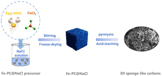
Figure 1.
A schematic diagram of three-dimensional sponge-like carbons.
2. Results and Discussion
2.1. Electrocatalyst Characterization
SEM is an important method for observing the surface characteristics of the catalysts. From SEM images (Figure 2a and Figure S1 in the Supplementary Materials), we can clearly see that Fe-PC@NaCl formed a spongy 3D porous structure. This is because the Fe-PC precursor was coated on the surface of the NaCl template and eluted with 0.1 M H2SO4 to form a three-dimensional sponge-like structure. This special structure was conducive to enhancing the specific surface area and provided more active sites so that the oxygen reduction reaction was easier to occur, and the mass transfer of oxygen was faster during the reaction. The corresponding TEM images are shown in Figure 2b. It can be seen from the image that Fe-PC@NaCl formed a connected spatial network structure through a thin carbon wall. The shapes of the pores were mainly spherical and cubic, and the structures of the pores were relatively complete. In element mapping results (Figure 2c), the C element was along the sphere surface with the N element sporadically bedded in it, which confirmed that N was successfully doped into the C skeleton. The Fe element was concentrated in the dense area found in the TEM images. At the same time, the O element was distributed similarly to the Fe mapping. This phenomenon indicated that the dense area in the TEM images was likely to be iron oxide.
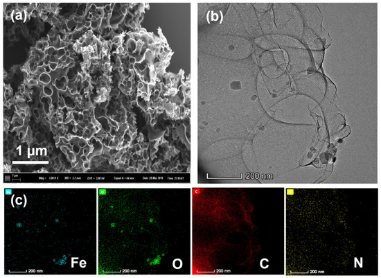
Figure 2.
(a) The SEM images of Fe-PC@NaCl; (b) The TEM images of Fe-PC@NaCl; (c) the elemental mapping of the Fe-PC@NaCl catalyst.
The XRD result in Figure 3a shows that FePC@NaCl-900, PC@NaCl-900, and FePC-900 were successfully doped with Fe and Fe3O4, while PC-900 was not. This confirms the doping of Fe and Fe3O4, as found previously in the TEM and element mapping images. TGA analysis was conducted to investigate the behavior during thermal treatment. As can be seen from Figure 3b, the curves of Pc-900 and FePC-900 have two primary phases of weight reduction. The first phase of mass reduction occurred from 25 °C to 100 °C, which was a minor weight loss due to dehydration. Next, the weight reduction in the second stage occurred from 200 °C to 400 °C, with a reduction of 50%, which was due to the decomposition and complexation of precursors. However, the curve of PC@NaCl-900 turned sharply at 810 °C, which was much higher than that of Pc-900 and FePC-900, proving that the thermal stability of the PC@NaCl-900 was better than that of Pc-900 and FePC-900. The weight reduction at this stage was due to the dissolution of the NaCl crystal.
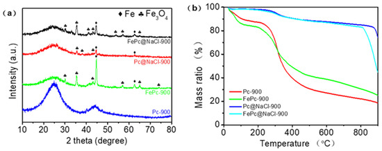
Figure 3.
(a) XRD patterns of FePC@NaCl-900, PC@NaCl-900, FePC-900 and PC-900, (b) TGA curves of FePC@NaCl-900, PC@NaCl-900, FePC-900 and PC-900.
X-ray photoelectron spectroscopy (XPS) was adopted to investigate the surface chemical composition and structure of the as-prepared catalysts. Figure 4 illustrates the detailed XPS analysis of the synthesized Fe-PC@NaCl. In the full spectra shown in Figure 3a, the main peaks from C1s, O1s, and N1s appeared, while the XPS peak of metal Fe could be slightly found owing to a very low content in Fe-PC@NaCl, which was consistent with the EDS elemental mapping. The presence of the N1 s peak indicates that N atoms are successfully incorporated into the graphite structure of carbon materials, which is powerfully supported by their C1s XP spectra (Figure 4b). The fitting C1s peaks located at 284.6, 285.8, 288.0 and 290.8 eV can be assigned to graphitic sp2 carbon, amorphous carbon, sp2 carbon atoms bonded to nitrogen, and sp2 carbon atoms bonded to oxygen, respectively [19,20].
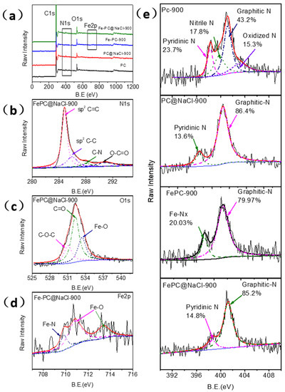
Figure 4.
(a) XPS full-scan spectra of the PC material, PC@NaCl-900, FePC-900, and FePC@NaCl-900. (b–d) High-resolution C1s, O1s, and Fe 2p XP narrow-scan spectra of FePC@NaCl-900. (e) High-resolution N1s XP narrow-scan spectra of the PC material, PC@NaCl-900, FePC-900, and Fe-PC@NaCl-900.
The O1s XPS spectrum of FePC@NaCl-900 (Figure 4c) is deconvoluted into three peaks centered at 530.8, 532.3, and 533.3 eV, corresponding to the C(aliphatic)-O-C(aliphatic), C=O, and metal-bounded oxygen (Fe-O), respectively. On the basis of the research results of the Fe 2p, N1s, and O1s XPS spectra, it can be concluded that Fe atoms are mainly in two forms, including Fe-N and Fe-O. The X-ray diffraction analysis proves the existence of oxidized metallic Fe particles (Fe3O4) in FePC@NaCl-900. The Fe 2p3/2 spectrum of Fe-PC@NaCl-900 was further analyzed in Figure 4d and can be deconvoluted into three peaks at 709.7, 710.8 and 713.8 eV. The peak at 708.4 eV corresponds to the characteristic peak of the Fe-N bond only [21]. The appearance of other peaks centered at 710.8 and 713.8 eV could be owing to the formation of various forms of iron oxides (710–713 eV).
The overall N content was only 1.66% and 1.67% in Fe-PC@NaCl and Fe-Pc but was 2.06% and 2.02% in PC@NaCl and PC. Figure 4e illustrates the N1 s XP spectra of Fe-PC@NaCl-900, Fe-Pc, and PC@NaCl and can be deconvoluted into two peaks, which are attributed and assignable to pyridinic-N (398.7 eV) and graphitic-N (401.2 eV). However, the N1 s XP spectra of PC can be deconvoluted into four distinct components centered at pyridinic-N (398.2 eV), nitrile N (399.7 eV), graphitic N (401.1 eV), and oxidized N (402.2 eV). The relative proportion of graphitic-N was only 43.2% in PC but was 85.2% (Fe-PC@NaCl-900), 86.4% (PC@NaCl), and 79.9% (FePC), respectively (Table S1). It is worthwhile to note that a lower total N content and higher relative proportion of graphitic-N were observed in Fe-PC@NaCl-900. This interesting phenomenon can be due to the phase change from the solid phase to the liquid phase of the NaCl aggregates. During the transformation process, some of the space-confined effects disappear, and the Fe-Nx decompositions lead to an increase in the graphitization of the catalyst and the generation of more active sites [9,22,23].
Due to the spongy 3D porous structure of the Fe-PC@NaCl, Raman spectroscopy was used to test the defect and disorder structure of the catalyst. As shown in Figure 5, there were two sharp characteristic peaks in the Raman spectra of each catalyst. One was the “D” peak, and the other was the “G” peak. The D peak at 1350 cm−1 was due to the lattice defects of carbon atoms. Additionally, the G peak at 1605 cm−1 was formed by the E2g mode for the in-phase stretching vibration of sp2-bonded carbon. The intensity ratio of the two peaks (ID/IG) could correctly reflect the defective degree of the catalyst structure. Among all the doped-carbon catalysts, the ID/IG ratio of Fe-PC@NaCl had the highest value of 1.76, which is larger than that of PC (1.45), Fe-PC (1.32), and PC@NaCl (1.29). The results show that Fe-PC@NaCl had the richest defect structure compared with other catalysts [24] and That the Fe-PC@NaCl had been effectively modified with N-rich products from the thermolysis of bioprotein inside the PC biomass [25].
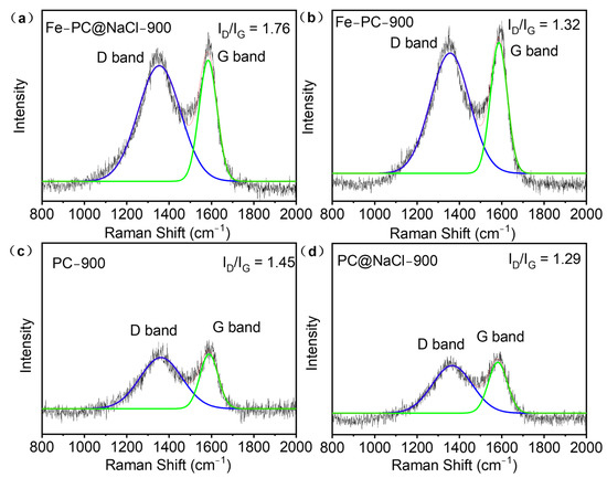
Figure 5.
(a–d) Raman spectra of PC, Fe-Pc, PC@NaCl, and Fe-PC@NaCl.
2.2. ORR Electrocatalytic Activity
All the doped-carbon catalysts, including PC, Fe-PC, PC@NaCl, and Fe-PC@NaCl, were tested by cyclic voltammetry (CV) under the same condition, i.e., in a 0.1 mol L−1 oxygen-saturated KOH solution. As demonstrated in Figure 6a and Figure S3a, their CV curves show a significant disparity between ORR electrocatalytic activities. Among them, Fe-PC@NaCl-900 shows the best ORR performance with Ep at 0.88 V and EORR at 1.04 V compared to PC@NaCl-900 (EORR: 0.92 V and Ep: 0.75 V). The increase in Ep and EORR is probably due to the addition of Fe2+ and the formation of Fe-N. Additionally, the ORR activity of Fe-PC@NaCl was also significantly higher than that of Fe-PC. This can be attributed to the template effect of NaCl, which promotes the catalyst to form a hollow structure and greatly improves the exposure of active sites. The linear sweep voltammetry (LSV) technique was also used to measure the polarization curves of all the doped-carbon catalysts by using a ring disk electrode (RDE), and the 1600 rpm was fixed (Figure 6b). It is obvious that the ORR activity of Fe-PC@NaCl-900 was the highest among the four catalysts, which was greatly improved compared with the other three catalysts. The onset potential (EORR) and half-wave potential (E1/2) of Fe-PC@NaCl-900 were 0.99 V and 0.852 V, respectively. Moreover, the limited current density of Fe-PC@NaCl-900 at 0.3 V was 1.36 mA. The above data are obviously higher than that of other catalysts, which fully proves that Fe-PC@NaCl-900 has the best ORR activity. At the same time, the effect of the calcination temperature on the catalytic performance of Fe-PC@NaCl for ORR was observed. It can be seen from Figure S3a (Supplementary Materials) that with the increase in the calcination temperature and the performance of Fe-PC@NaCl was also improved. When the calcination temperature reached 900 °C, the onset potential and half-wave potential of the catalyst reached the maximum. However, with the continuous rise in temperature, these indicators all dropped sharply, which can be closely related to the damage to the porous structure of the catalyst under high temperatures (Figure 6c). We also compared Fe-PC@NaCl-900 with other recent ORR catalysts [26,27,28,29,30,31,32,33,34] (Figure 6d). We found that the performance is comparable to those in the recent literature.
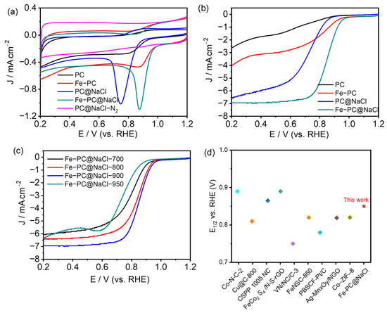
Figure 6.
(a) CV curves of PC, Fe-PC, PC@NaCl, Fe-PC@NaCl in O2, and PC@NaCl in N2-saturated 0.1 M KOH solution, respectively. (b) LSV curves of PC, Fe-PC, PC@NaCl, and Fe-PC@NaCl in O2-saturated 0.1 M KOH solution. (c) LSV curves of Fe-PC@NaCl-700,800,900,950 in O2-saturated 0.1 M KOH solution. (d) Comparison of half-wave potentials with the recent literature.
The ORR polarization curves measured on Fe-PC@NaCl-900 catalyzed electrodes in a 0.1 M KOH electrolyte over a range of electrode rotation rates (400–2500 rpm) are indicated in Figure 7a. A Koutechy-Levich (K-L) analysis was performed to further investigate the ORR kinetics by taking RDE measurements at various rotation speeds (Figure 7b), K-L plots were derived from the LSV curves, and the plots for all of the Fe-PC@NaCl-900 catalysts showed good linearity. According to the slopes of the K-L plots, the electron transfer number (n) for Fe-PC@NaCl-900 was 3.9, consistent with an efficient 4 e− process of the ORR. This process is the same as the Pt/C, which indicates that the energy barrier for the reaction of Fe-PC@NaCl-900 was comparable to that for Pt (III) [35]. The values of n for PC-900, Fe-PC-900, and PC@NaCl-900, were determined to be 2.8, 3.4, and 3.6, respectively (Figures S3b–S5, Supplementary Materials), and are indicative of both the two-and four-electron processes during the ORR.
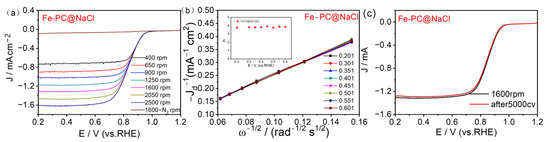
Figure 7.
(a) LSV curves of Fe-PC@NaCl-900 at various rotation rates. (b) K–L plots at various potentials. (c) LSV curves of Fe-PC@NaCl-900 before and after cycling for 5000 cycles with 1600 rpm RDE.
The oxygen reduction stability of the catalyst is the key data of the basic fuel cell technology research, which is directly related to its practical applications. An accelerated aging test (AAT) was used to test the stability of Fe-PC@NaCl (Figure 7c). Compared with the half-wave potential of the first test (0.852 V), the half-wave potential measured after 5000 cycles of the CV test (0.85 V) decreased by only 0.002 V, and the limiting diffusion current density also decreased by 0.03 mA. These results show that the catalytic performance of Fe-PC@NaCl synthesized in this study was kept basically unchanged after 5000 cycles of the CV test, which proves that the catalyst has excellent stability in the alkaline system, suggesting its excellent application prospects.
The kinetic process of ORR was studied by a rotating ring disk electrode (RRDE). The LSV curve of the catalyst was obtained at 1600 rpm on the RRDE. The level of the electrocatalytic activity of the pure egg white precursor and egg white precursor with FeCl3 was low. However, the level of electrocatalytic activity for the Fe-PC@NaCl with NaCl as a template was significantly improved. In addition, as shown in Figure 8, we also calculated the corresponding electron transfer (n) and peroxide species produced (H2O2−) in the ORR process. The high electron transfer number and low peroxide yield of the Fe-PC@NaCl in the range of 0.2–0.8 V indicated a direct four-electron pathway. Therefore, we can conclude that the Fe-PC@NaCl is a new ideal Fe-N-C catalyst.
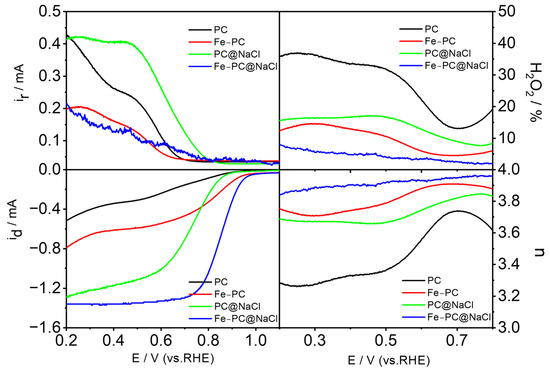
Figure 8.
The LSV curve of the catalyst was obtained at 1600 rpm on the RRDE, and the corresponding electron transfer (n) and peroxide species produced (H2O2−) in the ORR process.
3. Experimental
3.1. Synthesis of Catalysts
PC precursor: 5 g egg white and 20 mL water were stirred for 5 h at room temperature to obtain PC precursor.
Fe-Pc precursor: After 0.25 g, FeCl3 was ultrasonically dissolved in 20 mL water, and 5 g of egg white was added to this solution. Then, the solution was stirred for 5 h at room temperature to obtain the Fe-PC precursor.
PC@NaCl precursor: After 5 g, NaCl was ultrasonically dissolved in 20 mL of water, and 5 g of egg white was added to this solution. Then, the solution was stirred for 5 h at room temperature to obtain the PC@NaCl precursor.
Fe-PC@NaCl precursor: After, 0.25 g of FeCl3 and 5 g of NaCl were ultrasonically dissolved in 20 mL of water, and 5 g of egg white was added to this solution. Then, the solution was stirred for 5 h at room temperature to obtain the Fe-PC@NaCl precursor.
Subsequently, the PC precursor, Fe-Pc precursor, PC@NaCl precursor, and Fe-PC@NaCl precursor were freeze-dried and heated at 350 °C for 1 h and 900 °C for 2 h with a heating rate at 10 °C min−1 to gain PC-1, Fe-Pc-1, PC@NaCl-1, and Fe-PC@NaCl-1. Later, PC-1, Fe-Pc-1, PC@NaCl-1, and Fe-PC@NaCl-1 were ground, washed with 0.1 M H2SO4 solution 3 times, and then deionized water 2 times and heated at 900 °C for 1 h to obtain PC, Fe-Pc, PC@NaCl, and Fe-PC@NaCl, respectively. The diagrammatic synthesis of 3D sponge-like carbons is illustrated in Figure 1.
Additionally, the Fe-PC@NaCl precursor was separately freeze-dried and heated at 350 °C for 1 h and at 700 °C, 800 °C, 900 °C, or 950 °C for 2 h to gain Fe-PC@NaCl-700-1, Fe-PC@NaCl-800-1, Fe-PC@NaCl-900-1, and Fe-PC@NaCl-950-1, respectively. Then, Fe-PC@NaCl-700-1, Fe-PC@NaCl-800-1, Fe-PC@NaCl-900-1, and Fe-PC@NaCl-950-1 were ground, washed with a 0.1 M H2SO4 solution 3 times and then deionized water 2 times and heated at 700 °C, 800 °C, 900 °C, or 950 °C for 1 h to obtain Fe-PC@NaCl-700, Fe-PC@NaCl-800, Fe-PC@NaCl-900, and Fe-PC@NaCl-950, respectively.
3.2. Characterizations
The morphology and energy-dispersive spectroscopy (EDS) mapping analysis of the as-prepared catalyst were investigated using transmission electron microscopy (TEM) (Model JEM-2100, Tokyo, Japan) at an acceleration voltage of 200 kV. X-ray photoelectron spectroscopy (XPS) was performed on a Specs spectrometer (Thermo Fisher Scientific, Waltham, MA, USA) with Mg Kα (1253.6 eV) and radiation at 150 W. Binding energies were calibrated by setting C1s to 284.6 eV. Raman spectroscopy data were performed using a Renishaw inVia unit (Renishaw, London, UK) with excited 514.5 nm at room temperature. Field-emission scanning electron microscopy (FE-SEM) images were measured using Hitachi UHR S4800 (Hitachi, Tokyo, Japan). Powder X-ray diffraction (XRD) patterns of the samples were measured using an XRD-6000 X-ray diffractometer (Shimadzu, Kyoto, Japan).
3.3. Electrochemical Measurements
All electrochemical measurements were performed on an electrochemical analysis workstation (Zennium-E workstation, Gundelsdorf, Germany) using a conventional three-electrode device. A glass-carbon rotation ring-disk electrode (GC-RRDE, Φ = 5 mm, Pine Instrument Co., Durham, NC, USA), a saturated calomel electrode (SCE), and a graphite rod (Φ = 0.5 cm) were used as the working electrode (WE), reference electrode (RE), and auxiliary electrode (AE), respectively. The potential against SCE was converted into potential against RHE according to the Nernst equation:
where is 0.241 V at 25 °C [36].
The catalyst ink was prepared by dispersing 1.0 mg of each catalyst in 200 μL of the mixed solution containing water (160 μL), isopropanol (20 μL), and 5 wt% Nafion solution (20 μL), followed by ultra-sonication for 30 min to form a homogeneous black suspension solution.
The ORR performance of the catalysts was measured in an O2-saturated 0.1 M KOH solution. The cyclic voltammetry (CV) curves were obtained at a scan rate of 50 mV s−1.
Before the electrochemical test, the continuous cyclic voltammetry (CV) scanning for 10 cycles was performed in an N2-saturated 0.1 mol L−1 KOH solution to activate the carbon-based catalyzed electrode.
The H2O2% yield and the electron transfer number (n) during the ORR were calculated using the following equations [37]:
where Id is the faradaic current at the disk, Ir is the faradaic current at the ring, and N is the collection efficiency of the ring electrode (0.38). n was calculated using the Koutecky-Levich equation:
where F is the Faraday constant, Co is the O2 saturation concentration in the electrolyte, Do is the O2 diffusion coefficient in the electrolyte, ν is the kinetic viscosity of the electrolyte, ω is the electrode rotation speed, and 0.62 is a constant when the rotation rate is expressed in rpm.
4. Conclusions
In this paper, a new strategy with egg white and NaCl for the synthesis of three-dimensional sponge-like catalysts was studied. NaCl crystal particles were used as templates to effectively construct a three-dimensional porous hollow structure, improving the surface performance, conductivity, and proton transport efficiency of the catalyst. As a high-protein biomass, egg whites provide many carbon and nitrogen sources for the active sites of the oxygen reduction catalyst. The onset potential and half-wave potential of the synthesized catalyst (Fe-PC@NaCl) are 0.88 V and 0.73 V, respectively, which show excellent electrocatalytic performance. At the same time, the stability test results also suggest the excellent long-term electrochemical stability of Fe-PC@NaCl. In addition, the number of electron transfers and the yield of H2O2 are 3.742 and 4.32%, respectively, indicating that the catalyst follows a direct four-electron transfer pathway in an alkaline medium. This study provides a new pathway to synthesize high-performance catalysts using natural biomaterials.
Supplementary Materials
The following supporting information can be downloaded at: https://www.mdpi.com/article/10.3390/catal13010166/s1, Figure S1: TEM images of Fe-PC@NaCl-900; Figure S2: The elemental mapping of the Fe-PC@NaCl catalyst; Figure S3: (a) CV curves of Fe-PC@NaCl-700, 800, 900, 950 in O2 and Fe-PC@NaCl-950 in N2-saturated 0.1 M KOH solution, respectively, (b) The Ep, EORR and Jd of the PC-900, Fe-PC-900, PC@NaCl-900 and Fe-PC@NaCl-900; Figure S4: (a) LSV curves of PC-900 at various rotation rates, (b) K-L plots at various potentials; Figure S5: (a) LSV curves of PC@NaCl-900 at various rotation rates, (b) K-L plots at various potentials; Figure S6: (a) LSV curves of FePC-900 at various rotation rates, (b) K-L plots at various potentials; Table S1: N1s XPS results from Figure 4e.
Author Contributions
Conceptualization, Y.L., C.G., and Z.L. (Zhongli Luo); methodology, X.L., W.S. and, C.G.; validation, Y.L., Z.L. (Zhongli Luo); formal analysis, X.L. and Y.L. and X.L.; investigation, X.L. and W.S.; resources, Y.L., C.G. and Z.L. (Zhongli Luo); data curation, X.L. and Y.L.; writing—original draft preparation, X.L.; writing—review and editing, Y.L., W.L., Z.L. (Zhongbin Li), and C.G.; supervision, Z.L. (Zhongli Luo); project administration, W.L., Z.L. (Zhongbin Li), and Z.L. (Zhongli Luo); funding acquisition, C.G. and Z.L. (Zhongli Luo). All authors have read and agreed to the published version of the manuscript.
Funding
This research was funded by the National Natural Science Foundation of China grant number (Project No: 31771101), the Basic Research and Frontier Exploration Project of Chongqing Municipality (Project No: cstc2018 jcyjAX0461 and cstc2015 jcyjBX0072), and the Scientific and Technological Research Program of Chongqing Municipal Education Commission (KJQN201901335, KJ1711289, KJQN202001335 and KJQN202101313).
Data Availability Statement
The datasets generated during and/or analyzed during the current study are available from the corresponding author on reasonable request.
Conflicts of Interest
The authors declare no conflict of interest.
References
- Debe, M.K. Electrocatalyst Approaches and Challenges for Automotive Fuel Cells. Nature 2012, 486, 43–51. [Google Scholar] [CrossRef] [PubMed]
- Liang, Y.; Li, Y.; Wang, H.; Zhou, J.; Wang, J.; Regier, T.; Dai, H. Co3O4 Nanocrystals on Graphene as a Synergistic Catalyst for Oxygen Reduction Reaction. Nat. Mater. 2011, 10, 780–786. [Google Scholar] [CrossRef] [PubMed]
- Greeley, J.; Stephens, I.E.L.; Bondarenko, A.S.; Johansson, T.P.; Hansen, H.A.; Jaramillo, T.F.; Rossmeisl, J.; Chorkendorff, I.; Nørskov, J.K. Alloys of Platinum and Early Transition Metals as Oxygen Reduction Electrocatalysts. Nat. Chem. 2009, 1, 552–556. [Google Scholar] [CrossRef] [PubMed]
- Zhou, T.; Xu, W.; Zhang, N.; Du, Z.; Zhong, C.; Yan, W.; Ju, H.; Chu, W.; Jiang, H.; Wu, C.; et al. Ultrathin Cobalt Oxide Layers as Electrocatalysts for High-Performance Flexible Zn–Air Batteries. Adv. Mater. 2019, 31, 1807468. [Google Scholar] [CrossRef]
- Song, D.; Guo, H.; Huang, K.; Zhang, H.; Chen, J.; Wang, L.; Lian, C.; Wang, Y. Carboxylated Carbon Quantum Dot-Induced Binary Metal–Organic Framework Nanosheet Synthesis to Boost the Electrocatalytic Performance. Mater. Today 2022, 54, 42–51. [Google Scholar] [CrossRef]
- Pi, Y.; Zhang, N.; Guo, S.; Guo, J.; Huang, X. Ultrathin Laminar Ir Superstructure as Highly Efficient Oxygen Evolution Electrocatalyst in Broad PH Range. Nano Lett. 2016, 16, 4424–4430. [Google Scholar] [CrossRef]
- Banham, D.; Ye, S.; Pei, K.; Ozaki, J.I.; Kishimoto, T.; Imashiro, Y. A Review of the Stability and Durability of Non-Precious Metal Catalysts for the Oxygen Reduction Reaction in Proton Exchange Membrane Fuel Cells. J. Power Sources 2015, 285, 334–348. [Google Scholar] [CrossRef]
- Guo, C.; Liao, W.; Chen, C. Fe/N/C Catalysts Derived from Blood Protein and Their Electrocatalytic Activity towards the Oxygen Reduction Reaction in Acidic Solution. Chin. Sci. Bull. 2014, 59, 3424–3429. [Google Scholar] [CrossRef]
- Guo, C.; Liao, W.; Li, Z.; Sun, L.; Chen, C. Easy Conversion of Protein-Rich Enoki Mushroom Biomass to a Nitrogen-Doped Carbon Nanomaterial as a Promising Metal-Free Catalyst for Oxygen Reduction Reaction. Nanoscale 2015, 7, 15990–15998. [Google Scholar] [CrossRef]
- Jaouen, F.; Proietti, E.; Lefèvre, M.; Chenitz, R.; Dodelet, J.P.; Wu, G.; Chung, H.T.; Johnston, C.M.; Zelenay, P. Recent Advances in Non-Precious Metal Catalysis for Oxygen-Reduction Reaction in Polymer Electrolyte Fuel Cells. Energy Environ. Sci. 2010, 4, 114–130. [Google Scholar] [CrossRef]
- Sun, M.; Davenport, D.; Liu, H.; Qu, J.; Elimelech, M.; Li, J. Highly Efficient and Sustainable Non-Precious-Metal Fe-N-C Electrocatalysts for the Oxygen Reduction Reaction. J. Mater. Chem. A Mater. 2018, 6, 2527–2539. [Google Scholar] [CrossRef]
- Jasinski, R. A New Fuel Cell Cathode Catalyst. Nature 1964, 201, 1212–1213. [Google Scholar] [CrossRef]
- Yao, Z.C.; Tang, T.; Hu, J.S.; Wan, L.J. Recent Advances on Nonprecious-Metal-Based Bifunctional Oxygen Electrocatalysts for Zinc-Air Batteries. Energy Fuels 2021, 35, 6380–6401. [Google Scholar] [CrossRef]
- Zhang, X.; Xu, X.; Yao, S.; Hao, C.; Xiang, X.; Tian, Z.Q.; Shen, P.K.; Shao, Z.; Jiang, S.P.; Zhang, X.; et al. Boosting Electrocatalytic Activity of Single Atom Catalysts Supported on Nitrogen-Doped Carbon through N Coordination Environment Engineering. Small 2022, 18, 2105329. [Google Scholar] [CrossRef] [PubMed]
- Liu, R.; Zhang, H.; Liu, S.; Zhang, X.; Wu, T.; Ge, X.; Zang, Y.; Zhao, H.; Wang, G. Shrimp-Shell Derived Carbon Nanodots as Carbon and Nitrogen Sources to Fabricate Three-Dimensional N-Doped Porous Carbon Electrocatalysts for the Oxygen Reduction Reaction. Phys. Chem. Chem. Phys. 2016, 18, 4095–4101. [Google Scholar] [CrossRef]
- Wang, H.; Zhang, Z.; Yang, Y.; Wang, K.; Ji, S.; Key, J.; Ma, Y.; Wang, R. A Co-N-Doped Carbonized Egg White as a High-Performance, Non-Precious Metal, Electrocatalyst for Oxygen Reduction. J. Solid State Electrochem. 2015, 19, 1727–1733. [Google Scholar] [CrossRef]
- Wang, H.; Wang, K.; Key, J.; Ji, S.; Linkov, V.; Wang, R. Egg White Derived Tremella-like Mesoporous Carbon as Efficient Non-Precious Electrocatalyst for Oxygen Reduction. J. Electrochem. Soc. 2014, 161, H637–H642. [Google Scholar] [CrossRef]
- Zhang, Z.; Gao, Z.; Yan, Z.; Dai, C.; Kesse, I.; Zhao, X.; Xie, J. Porous Carbonized Egg White as Efficient Electrocatalyst for Oxygen Reduction Reaction. Int. J. Hydrogen Energy 2021, 46, 21112–21123. [Google Scholar] [CrossRef]
- Wang, Z.; Jin, X.; Zhu, C.; Liu, Y.; Tan, H.; Ku, R.; Zhang, Y.; Zhou, L.; Liu, Z.; Hwang, S.-J.; et al. Atomically Dispersed Co2-N6 and Fe-N4 Costructures Boost Oxygen Reduction Reaction in Both Alkaline and Acidic Media. Adv. Mater. 2021, 33, 2104718. [Google Scholar] [CrossRef]
- Li, Y.; Guo, C.; Li, J.; Liao, W.; Li, Z.; Zhang, J.; Chen, C. Pyrolysis-Induced Synthesis of Iron and Nitrogen-Containing Carbon Nanolayers Modified Graphdiyne Nanostructure as a Promising Core-Shell Electrocatalyst for Oxygen Reduction Reaction. Carbon N. Y. 2017, 119, 201–210. [Google Scholar] [CrossRef]
- Artyushkova, K.; Walker, C.; Patterson, W.; Atanassov, P. Hierarchically Structured Non-PGM Oxygen Reduction Electrocatalyst Based on Microemulsion-Templated Silica and Pyrolyzed Iron and Cyanamide Precursors. Electrocatalysis 2014, 5, 241–247. [Google Scholar] [CrossRef]
- Guo, C.; Hu, R.; Liao, W.; Li, Z.; Sun, L.; Shi, D.; Li, Y.; Chen, C. Protein-Enriched Fish “Biowaste” Converted to Three-Dimensional Porous Carbon Nano-Network for Advanced Oxygen Reduction Electrocatalysis. Electrochim. Acta 2017, 236, 228–238. [Google Scholar] [CrossRef]
- Guo, C.; Li, Y.; Liao, W.; Liu, Y.; Li, Z.; Sun, L.; Chen, C.; Zhang, J.; Si, Y.; Li, L. Boosting the Oxygen Reduction Activity of a Three-Dimensional Network Co–N–C Electrocatalyst via Space-Confined Control of Nitrogen-Doping Efficiency and the Molecular-Level Coordination Effect. J. Mater. Chem. A Mater. 2018, 6, 13050–13061. [Google Scholar] [CrossRef]
- Zhou, J.; Gao, X.; Liu, R.; Xie, Z.; Yang, J.; Zhang, S.; Zhang, G.; Liu, H.; Li, Y.; Zhang, J.; et al. Synthesis of Graphdiyne Nanowalls Using Acetylenic Coupling Reaction. J. Am. Chem. Soc. 2015, 137, 7596–7599. [Google Scholar] [CrossRef] [PubMed]
- Mo, Z.; Zheng, R.; Peng, H.; Liang, H.; Liao, S. Nitrogen-Doped Graphene Prepared by a Transfer Doping Approach for the Oxygen Reduction Reaction Application. J. Power Sources 2014, 245, 801–807. [Google Scholar] [CrossRef]
- Wang, W.; Han, N.; Ge, D.; Liao, L.; Li, M.; Yin, Y. Metal-Organic Framework-Derived Atomically Dispersed Co-N-C Electrocatalyst for Efficient Oxygen Reduction Reaction. Catalysts 2022, 12, 1462. [Google Scholar] [CrossRef]
- Zhang, D.; Li, Y.-F.; Liu, L.-X.; Duan, L.; Ren, Z.-L.; Xu, S.-D.; Chen, L.; Guo, H.-J.; Huang, Y.; Shi, L.-J.; et al. Cu/CuOx@C Composite as a High-Efficiency Electrocatalyst for Oxygen Reduction Reactions. Catalysts 2022, 12, 1515. [Google Scholar] [CrossRef]
- Cheng, M.; Bhalothia, D.; Yeh, W.; Beniwal, A.; Yan, C.; Wang, K.-W.; Chen, P.-C.; Tu, X.; Cheng, M.; Bhalothia, D.; et al. Optimization of SnPd Shell Configuration to Boost ORR Performance of Pt-Clusters Decorated CoOx@SnPd Core-Shell Nanocatalyst. Catalysts 2022, 12, 1411. [Google Scholar] [CrossRef]
- Zhang, W.L.; Liu, S.M.; Zhang, L.H.; He, T.T.; Yu, F.S. Interfacial Electron Redistribution of FeCo2 S4/N-S-RGO Boosting Bifunctional Oxygen Electrocatalysis Performance. Catalysts 2022, 12, 1002. [Google Scholar] [CrossRef]
- Fu, Y.; Han, L.; Zheng, P.; Peng, X.; Xian, X.; Liu, J.; Zeng, X.; Dong, P.; Xiao, J.; Zhang, Y. Vanadium Nitride Supported on N-Doped Carbon as High-Performance ORR Catalysts for Zn–Air Batteries. Catalysts 2022, 12, 877. [Google Scholar] [CrossRef]
- Liu, Y.; Xu, Y.; Wang, H.; Zhang, J.; Zhao, H.; Chen, L.; Xu, L.; Xie, Y.; Huang, J. MIL-88-Derived N and S Co-Doped Carbon Materials with Supplemental FeSx to Enhance the Oxygen Reduction Reaction Performance. Catalysts 2022, 12, 806. [Google Scholar] [CrossRef]
- Wang, C.; Zheng, Z.; Chen, Z.; Luo, X.; Hou, B.; Gholizadeh, M.; Gao, X.; Fan, X.; Tan, Z. Enhancement on PrBa0.5Sr0.5Co1.5Fe0.5O5 Electrocatalyst Performance in the Application of Zn-Air Battery. Catalysts 2022, 12, 800. [Google Scholar] [CrossRef]
- Wolf, S.; Roschger, M.; Genorio, B.; Kolar, M.; Garstenauer, D.; Bitschnau, B.; Hacker, V. Ag-MnxOy on Graphene Oxide Derivatives as Oxygen Reduction Reaction Catalyst in Alkaline Direct Ethanol Fuel Cells. Catalysts 2022, 12, 780. [Google Scholar] [CrossRef]
- Cui, N.; Bi, K.; Sun, W.; Wu, Q.; Li, Y.; Xu, T.; Lv, B.; Zhang, S. Effect of Pyrolysis Conditions on the Performance of Co-Doped MOF-Derived Carbon Catalysts for Oxygen Reduction Reaction. Catalysts 2021, 11, 1163. [Google Scholar] [CrossRef]
- Xiang, Q.; Yin, W.; Liu, Y.; Yu, D.; Wang, X.; Li, S.; Chen, C. A Study of Defect-Rich Carbon Spheres as a Metal-Free Electrocatalyst for an Efficient Oxygen Reduction Reaction. J. Mater. Chem. A Mater. 2017, 5, 24314–24320. [Google Scholar] [CrossRef]
- Sonkar, P.K.; Prakash, K.; Yadav, M.; Ganesan, V.; Sankar, M.; Gupta, R.; Yadav, D.K. Co(II)-Porphyrin-Decorated Carbon Nanotubes as Catalysts for Oxygen Reduction Reactions: An Approach for Fuel Cell Improvement. J. Mater. Chem. A Mater. 2017, 5, 6263–6276. [Google Scholar] [CrossRef]
- Wu, J.; Yang, Z.; Wang, Z.; Sun, Q.; Yang, R. Synthesis and Electrocatalytic Activity of Phosphorus and Co Co-Doped Mesoporous Carbon for Oxygen Reduction. Electrochem. Commun. 2014, 42, 46–49. [Google Scholar] [CrossRef]


Disclaimer/Publisher’s Note: The statements, opinions and data contained in all publications are solely those of the individual author(s) and contributor(s) and not of MDPI and/or the editor(s). MDPI and/or the editor(s) disclaim responsibility for any injury to people or property resulting from any ideas, methods, instructions or products referred to in the content. |
© 2023 by the authors. Licensee MDPI, Basel, Switzerland. This article is an open access article distributed under the terms and conditions of the Creative Commons Attribution (CC BY) license (https://creativecommons.org/licenses/by/4.0/).