Review

Development of Adsorptive Materials for Selective Removal of Toxic Metals in Wastewater: A Review

by
Moeng Geluk Motitswe
1,
Kassim Olasunkanmi Badmus
2,* and
Lindiwe Khotseng
1
1
Chemistry Department, University of the Western Cape, Cape Town 7535, South Africa
2
Industrial Chemistry Department, First Technical University, Ibadan 200255, Nigeria
*
Author to whom correspondence should be addressed.
Catalysts 2022, 12(9), 1057; https://doi.org/10.3390/catal12091057
Submission received: 12 July 2022 / Revised: 26 August 2022 / Accepted: 26 August 2022 / Published: 16 September 2022
(This article belongs to the Special Issue Heterogeneous Catalysts for Organic Wastewater Treatment)

Abstract

:
Removal of toxic metals is essential to achieving sustainability in wastewater purification. The achievement of efficient treatment at a low cost can be seriously challenging. Adsorption methods have been successfully demonstrated for possession of capability in the achievement of the desirable sustainable wastewater treatment. This review provides insights into important conventional and unconventional materials for toxic metal removal from wastewater through the adsorption process. The importance of the role due to the application of nanomaterials such as metal oxides nanoparticle, carbon nanomaterials, and associated nanocomposite were presented. Besides, the principles of adsorption, classes of the adsorbent materials, as well as the mechanisms involved in the adsorption phenomena were discussed.

1. Introduction

Water covers 71% of the Earth’s surface and is essential for the well-being of biotic and abiotic species (plants, soils, humans, and animals). Rapid global urbanization has led to increased pressure on water demands. The small amount of freshwater (3%) on Earth’s crust is available for human use, whereas most of the freshwater is trapped in the ice caps and glaciers (makes 68.7% of 3% of available freshwater on Earth) [1]. However, water contamination and management (use and treatment) are significant challenges worldwide.
Amongst the pollutants, toxic metals are reported to possess a non-biodegradable, persistent, highly stable, water-soluble, and recalcitrant nature in water media, making the efficiency of remediation methods complex [2,3,4]. The toxic metals contaminations can be caused by human anthropogenic activities (battery, tannery, textile, domestic sewages, mine and smelting industries, etc.) and natural occurrences (stormwater runoff/s, volcanic eruptions, mineral weathering, forest fires, soil erosion, etc.) [5,6,7]. They are described as metals with a density equal to or greater than 5 g/cm3, an atomic number greater than 11, and the tendency for metals to bio-accumulate in both living and non-living matters, posing chronic and acute health risks. The immediate effect of the toxic metals in the environment is marine ecosystem disintegration and soil degradation [8].
The remediation of toxic metal-contaminated wastewater needs good quality, selective, stable (catalytic, thermal, mechanical), reproducible and reusable materials to be employed in treatment systems [9,10]. Several treatment methods, namely, membrane technology, flocculation, coagulation/flocculation, chemical precipitation, ion exchange, electrochemical methods, phytoremediation, and biological methods, have been used for water and wastewater remediation [11,12].
Most current conventional methods are ineffective for toxic metal removal in the range of 1–100 mg/L. Besides, they are associated with demerits such as expensive disposal procedures, elevated chemical use, high energy consumption, a large formation of sludge/secondary pollutants, and sensitive operating conditions [13]. In overcoming these drawbacks, adsorption methods have proven more suitable, practical, and proficient for toxic metal removal in wastewater due to fast kinetics, high uptake capacities, efficiencies, selectivity, and simplicity [14]. The process is based on the net metal accumulation at the surface of the solid phase (adsorbent), and the efficiency is more attributed to the adsorbent’s nature. The adsorption consists of three phases: transport of the adsorbate from the liquid phase to the solid adsorbent surface, adsorption of the analytes onto the solid adsorbent surface, and transportation of adsorbate within the adsorbent particle [13]. Consequently, the current paper presents adsorption processes as an efficient method for removing toxic metal contaminants from wastewater. The different classes of materials, as well as the principle of adsorption, were also discussed.

2. Types of Adsorption

The adsorption types are chemisorption and physisorption (Table 1). The chemisorption is the binding of the adsorbate onto the adsorbent surface through strong ionic or covalent bonds. The factors such as pH, contact time, ionic strength, temperature, and adsorbent dosage can affect its efficiency [15,16]. Meanwhile, the physisorption occurs due to weak electrostatic interactions involving dipole-dipole, van der Waals, and London force [17,18]. The Dubinin–Radushkevish, Freundlich, Brunauer–Emmet–Teller, Jovanovich, Linear, Redlich–Peterson, and Temkin adsorption isotherms are essential models employed to differentiate physisorption from chemisorption isotherms (Langmuir, Sips, Volmer, Redlich–Peterson) [19,20].

3. Adsorption Isotherm and Kinetic

The adsorption kinetics and isotherm models are described in this review to better understand the adsorptive materials’ performance toward the adsorbates. These models are ranked from weak to suitable components for a thorough understanding of chemisorption and physisorption [21].

3.1. Adsorption Isotherm Model

The isotherm models describe the relationship between the liquid state equilibrium adsorbate and the amount of equilibrium adsorption on the solid state at a specific temperature (Table 2). These isotherms are readily helpful for analyzing the adsorbent’s adsorption capacities and efficiencies. The adsorption isotherms have been determined through numerous models: Langmuir, Freundlich, Sips, Dubinin–Radushkevish, Linear (Henry’s Law), Redlich–Peterson, and Temkin models [22].

3.2. Adsorption Kinetic Model

These models describe the relationship between the adsorbed adsorbate amount (qt) and the contact time (t). Due to the occurrence of chemical reactions, kinetic prediction is vital for the adsorption system design and determination of the reaction rate-controlling step. Additionally, the adsorption nature depends on the physicochemical characterization of the adsorbent and reaction conditions such as temperature, pH, dosage, and ionic strength. These models include pseudo-first-order, pseudo-second-order, Elovich, and intraparticle diffusion models.

3.2.1. Pseudo-First-order Model

The model describes the adsorption of liquid-solid state systems based on the adsorption capacity. The Pseudo-first-order model supposes that a single adsorbate is adsorbed onto a single active adsorptive site [23]. The linear expression is as follows:
log ( q e   q t ) = log ( q e ) ( k 1 2.303 )
where qe—adsorption capacity at equilibrium (mg/g), qt—adsorption capacity at time t (mg/g), k1—rate constant of pseudo-first-order adsorption (1/min)

3.2.2. Pseudo-Second-Order Model

This kinetic model describes the adsorption based on the adsorption capacity of the solid phases. It is commonly used for chemisorption kinetic rates. The equation for this model is:
t q t = 1 k 2 q e 2 + t q e
where k1—rate constant of pseudo-second-order adsorption (g/mg·min)

3.2.3. Intraparticle Diffusion Model

The drawback of the pseudo-first and pseudo-second-order models is that they cannot consider the diffusion and rate-controlling steps in the adsorbate molecule transportation [24]. Consequently, the intraparticle diffusion kinetic model was introduced to overcome the limitation. The equation can be written as follows:
q t = k p t 1 2 + C
where kp—intraparticle diffusion rate constant (mg/g min1/2), C—intercept of the intraparticle model plot. To recognize that the intraparticle diffusion has been obeyed, the plot should be linear, and only if the lines pass through the point of origin is intraparticle diffusion considered the rate-controlling step. But when the plot fails to pass through the origin, the implication is that intraparticle diffusion may not be the only rate-limiting step. Other kinetic models may be responsible for controlling the adsorption rate due to their input to the net transport of the adsorbate ions.

3.2.4. Elovich Model

This model has been reported as compatible with describing the adsorption system when the adsorbate species and the adsorbent sites interact chemically via a second-order mechanism [25]. Representation of the linear equation of the Elovich kinetic model is as follows:
q t = 1 β ln ( 1 + t β α )
where qt (mg/g) is the adsorbed adsorbate amount at time t, α is the initial rate constant (mg/g·min), and β is the desorption constant (g/mg).

4. Materials for Adsorption of Toxic Materials in Wastewater

Adsorptive materials are classified into two main groups, conventional and nanostructured materials, and their difference is seen in their sizes, shapes, and removal capacities toward water pollutants [26]. As a result, the current review will be on the selected and frequently used adsorbents for efficient toxic metal uptake.
These adsorbents are the usual types for wastewater remediation [27]. They are naturally available and can be easily derived from waste materials or applied in their pristine form [13]. These adsorbents are activated carbons, zeolites, industrial solid waste, biomaterials, and clay minerals. Conventional adsorption materials are costly, a significant limitation to their industrial application. Consequently, non-conventional adsorbents are products and by-products of biological (algae, bacteria, fungi, and yeasts), industrial (red mud, sludge), agricultural materials (cellulose, starch, and chitosan, bark, sawdust, peat) as well as nanoparticles are increasingly becoming popular. The non-conventional materials have advantages as adsorbents because of their abundance and attractive physicochemical characteristics [28].

4.1. Activated Carbons

Activated carbons (ACs) are commonly used as adsorbents in aqueous media due to their porous surface (large micropore and mesopore), improved specific surface area, as well as various compositional groups which bound to graphite-like layered edges [29,30]. The ACs’ adsorption behavior depends on the functional groups, pore size, and distribution [5,13]. Some carbonaceous precursors used to synthesize ACs are biological, fruit, plastic, agricultural, and vegetable wastes [5,31]. The materials are well known for retaining particular compounds and the preferential characteristic of resultant high-performance adsorption [32,33]. Due to the capital expenditure on coal-derived ACs, various agricultural wastes have been used for ACs synthesis. Invariably, there is a resultant positive impact on industrial and agricultural wastes in terms of reduced cost
There are numerous physical and chemical activation agents used for AC production. Some chemical activating agents are KOH, ZnCl2, H3PO4, and physical activations are steam atmosphere, air, and CO2 [30].

4.1.1. Chemical Activation Method

The method is based on a single-step reaction involving impregnating suitable reagents into the raw carbon source. Some activation agents include alkali metal-based salts and acids/bases (HCl, HNO3, H3PO4, H2SO4, NaOH, KOH) [34]. In this method, the enhanced surface area of ACs (>3000 m2/g) under low employed temperature can be achieved compared to physically modified ACs. The activated carbon has been produced from the flower of the golden shower tree through chemical activation, which yielded a large surface area of 1413 m2/g [35]. The method’s advantages are scalability, good pore growth, and less energy and consumption. However, the purification process may not be trivial for residual impurity removal. The method may use corrosive and hazardous chemicals, which could threaten waste disposal [36]. KOH chemically activated the Eichhornia (water hyacinth) with surface area (900 m2/g) and average pore diameter (21.6 Å) [37]. The adsorption data followed Freundlich and pseudo-second-order models with adsorption of Cd and Pb as 49.5 and 102 mg/g. The optimum adsorption was achieved at pH = 7, adsorbent dose (50 mg) at a temperature of 30 °C. The teak sawdust was also used to produce AC by hydrothermal/chemical activation using ZnCl2. The adsorption capacities achieved were 208 and 182 mg/g for Cd and Cu by the Langmuir model. Further exploration was that the oxygen functional groups readily accounted for pronounced adsorption output and the complexation mechanism was superior to the electrostatic interaction. The Eucalyptus camaldulensis was chemically activated by H2SO4 to remove Cd, Pb, and Cr from the wastewater through adsorption batch experiments [38]. The data obey the Langmuir model with adsorption capacities of 47.62, 6.17, and 9.26 mg/L for Cr, Cd, and Pb (with basic solution (pH 10–12)), thus suggesting a monolayer coverage adsorption system.

4.1.2. Physical Activation Method

This method involves pyrolysis, which majorly occurs at high temperatures. Generally, the process involves two main steps (carbonization of carbon materials in an inert atmosphere and, lastly, the resultant material activation in the presence of gasification reactants like steam atmosphere, air, CO2, and their mixture). The activation temperatures are typically in the range of 700–1100 °C. The reaction between the water and the gas can be assembled as follows:
C + H2O → CO + H2
C + 2H2O → CO2 + 2H2
The carbon is gasified, and porous, highly activated carbon is produced.
This process involves two steps: carbonization of carbonaceous materials in an inert atmosphere and activating the resulting materials in carbon gasification agents such as stream, air, and carbon dioxide. The sewage sludge was activated through heating at 800 °C for effective removal of Cu, Cd, and Pb from the wastewater, and the optimum removal parameters were pH = 6, room temperature, for 60 min, and that afforded the Freundlich (for Cd, Pb), and Langmuir (Cu) with a removal efficiency of 99.5, 97.7 and 93.7%, respectively [39]. The Ulva Lactuca was also activated at 800 °C for 3 h for batch adsorption of Cu, Cr, Cd, and Pb with 84.7, 82, 84.6, and 83.3 mg/g at pH 5 and equilibrium time (1 h) using Langmuir model, respectively [40]. The merits of the method are avoiding impurities typically sourced from an activating agent, inexpensive, no need for post-synthesis purification, and non-corrosive procedure. In contrast, the possible demerits are longer synthesis time, high pressure and temperature use, and weak control of porosity [41].

4.2. Zeolites

They are defined as 3D crystalline alumina silicates sourced from the interlinked tetrahedral arrangement of silica (SiO4) and alumina (AlO4) moieties [26,30]. The attributes of the tetrahedral zeolites framework are reversible dehydration and ion exchange. Zeolites have industrial and scientific importance due to their large surface area, improved ion exchange properties, inexpensive hydrophilic characteristics, and abundance, which result in their suitability for efficient toxic metals uptake from wastewater effluents [42,43]. These materials can occur naturally and also be synthesized [44,45]. The most abundant natural zeolite is clinoptilolites for effectively removing the metal species. However, they suffer the good pore size and impurity presence [44]. As a result, the synthetic counterparts exhibit even better adsorptive behavior and affinity for metallic adsorbates [46,47]. The zeolite preparation can also be achieved via sol-gel, hydrothermal, and microwave methods, which are presented and briefly discussed in this review.
Sol-gel synthesized faujasite X zeolite was studied for removal of several metals and examination of multiple adsorption parameters resulting in efficiency greater than 70% for metal and followed the order Zn > Cu > Pb > Fe from the municipal wastewater [48]. The hydrothermally derived incinerator ash zeolite was applied for the removal test of Cd, Cr, and Pb batch mode [49]. The modified zeolite afforded higher removal efficiency (84, 99, and 78% for Cr, Cd, Pb) than the natural zeolite in industrial wastewater and simulated metal solution samples under optimized conditions (60 min. and 1 mg of adsorbent). In the order study, the sol-gel assisted calcination method was used to prepare Faujasite for uptake of Pb, Zn, Cu, Cd, Fe, and Cr from industrial wastewater with an efficient range of 19.27–86.47% [50]. The tested equilibrium data and kinetics have followed the Langmuir model (homogenous adsorption system characteristic) and pseudo-second-order. The Na-zeolite P1 was synthesized by NaOH treatment, and the achieved surface area was 40 m2/g compared to raw pumice (31 m2/g). The pore volume of Na-zeolite P1 (0.02 cm3/g) was two-fold of the pumice [51]. The maximum obtained efficiencies under the optimized system were Cu (76%), Cd (98%), and Fe (76%). The equilibrium was achieved within a small contact time (8 min) due to the availability of the unoccupied adsorbent’s surface area, thus qualifying a faster adsorption rate. Furthermore, the high removal efficiencies may also be attributed to the adsorption mechanism and possible ion exchange occurrence [52]. The homogenous and heterogenous surface presence of Na-zeolite P1 was evidenced by equilibrium data obeying the Langmuir and Freundlich models. In contrast, the adsorption rate was well described by pseudo-second-order (characteristic of possible chemisorption, adsorption rate on the adsorbent surface is the responsible agent for rate controlling step).

4.3. Clay Minerals

These are types of materials readily found in nature. The clay products are hydrous aluminosilicates composed of weathered rocks, water, alumina, and silica and are well known to be 4 μm in at least 1-D [20]. Their standard features (large ratio of surface area to volume, pore volume, and small sizes) produce extraordinary catalytic and improved cation exchange capacities [7]. Moreover, the porous surface houses attractive forces suggesting the possible high bonding power [53]. The adsorptive removal of the toxic metal in wastewater via clay mineral may reasonably be achieved through complex adsorption mechanism series like direct bonding involving surface complexation, ion exchange, and direct contact uptake between clay mineral surface with cationic adsorbates [54]. The standard structural units are Al-O octahedral and Si-O tetrahedral layers bond to oxygen [55]. Based on structural arrangements and surface constituents, the clay minerals are mainly grouped into bentonite, mica, and kaolinite [56].
The bentonite is a sedimentary rock made up of a 2:1 layer clay structure and cations (Na, Ca, Mg, Fe) situated between the sheets. The tetrahedral and octahedral layers are patterned so that tetrahedral tips in each silica layer and mono-hydroxyl layer qualify as a monolayer [7].
The kaolinite clay minerals are a 1:1 layered structure composed of octahedral and tetrahedral SiO4 layers. Moreover, the hydrogen atom accumulation with other minerals tends to constitute the clays’ metal cation adsorption in an aqueous medium [57].
Lastly, the Mica group consists of a 2:1 layered structure with substitution (Si4+ substituted by Al3+) occurring in tetrahedral sheets by clay minerals [58,59].
There are naturally found and modified clay minerals for improving porosity, surface area, and affinitive surface. These developments are commonly achieved through physical and chemical treatments, viz. acid activation, salts, bases, thermal, surfactants, and supported on polymers [60,61].

4.3.1. Thermal Treatment of Clay

The heat treatment for synthesis may transform and tune the clay crystallinity, size, shape, and amorphization of porous nature. The thermal activation process is partitioned into temperature ranges for successful synthesis. The first one is the temperature beyond the dehydration (where records have shown that minerals like kaolinites tend to change to amorphous pore shapes). The second classification of temperature ranges is temperatures between dihydroxylation (process lowers structural water and transforming micro and macro porosity) and dehydration (elimination of adsorbed waters). The third temperature entails more crystalline phase generation (starting crystallographic orientation change) [62].
The thermal treatment does not utilize multiple chemicals for clay synthesis. However, determining adequate calcination temperature for multiple clay products may be difficult and extreme conditions may also result in clay mineral structural disintegration [61].

4.3.2. Acid Activation of Clay

During the acid activation of the clay, the first step in this process involves protons intercalation between clay intersheet spaces. The following footprint consists of dissolution cations and orientation on the silicate sheet. In most cases, the acid activation is performed using acids such as hydrochloric and sulfuric acid [63]. This activation has improved acidity, porosity, and surface size for catalysis on toxic metal adsorption. The common acids utilized for activation are nitric, hydrochloric, sulfuric, and phosphoric acids [64].

4.3.3. Polymerization of Clay

Due to their exceptional physical and chemical properties, the polymerization and surfactant-assisted polymerization of clay minerals have attracted use in environmental remediation applications. In this process, the ordering with the clay intersheet space tends to depend on the chain length, density, and applied temperature [65]. Some used polymers include polyurethanes, polyvinyl chloride, polystyrene, polyethylene terephthalate, polyimides, and polyesters [65,66].

5. Nanotechnology

Nanotechnology presents an extraordinary platform for synthesizing adsorbents with better capacity for uptaking pollutants and toxicity mitigation in wastewater [67,68,69]. This technology encompasses atomic material modification between 1 to 100 nanometers in size. The resultant nanomaterial has better chemical, physical, mechanical, and catalytic properties than its bulk material counterparts [61]. Due to their features which include low heat modifications, multiple active adsorption sites, tunable pore structure and size, large specific surface area, and short intraparticle diffusion length. Nanomaterials have been coupled with adsorption methods for achieving better toxic metal removal from wastewater [70]. A good adsorbent is considered a nanomaterial that is preferably non-toxic, possesses greater absorptivity, consumes less energy, is recyclable, and is reusable [71]. Amongst them are carbon-based nanomaterials, metal oxide nanoparticles, and nanocomposites. Nanomaterials are categorized as nanolayer/sheet, nanotubes, nanoparticles, nanospheres, nanowires, etc.

5.1. Metal Oxide Nanoparticle

In recent years, nanostructured metal oxide has proved to be the best candidate for wastewater treatment via an adsorption mechanism [72]. As some common characteristics associated with nanomaterial, metal oxide nanoparticles are no exception because they possess large pore volumes, surface area, high adsorption capacity, well pore sizes, and functionalized site/s [73]. Some nanosized metal oxide nanoparticles are zinc, manganese, aluminum, zirconium, iron, titanium, magnesium, etc.

5.1.1. Iron Oxide-Based Nanoparticles

The fourth abundant element in Earth’s crust is iron. The availability and ease of fabricating iron oxides have resulted in extensive studies on these nanomaterials. They have better adsorption capacity, affinity, and quicker adsorption rate than other adsorbing materials. Iron nanomaterials are readily used for toxic metal adsorption from water and wastewater. Iron-based nanomaterials may be classified into maghemite (γ-Fe2O3), goethite (α-FeOOH), magnetite (Fe3O4), hydrous ferric oxides (HFO), and hematite (α-Fe2O3). The most commonly used iron forms are α-Fe2O3, Fe3O4, and γ-Fe2O3 due to chemical stability, magnetism, less toxicity, and large surface area [74].

Magnetite (Fe3O4)

The cubic ferromagnetic magnetite is efficiently used for metallic pollutants adsorption due to its magnetic property, enabling simple separation and regeneration of the adsorbent from the aqueous solution [75]. Multiple investigations for removing toxic metals have been performed and documented [76]. The smaller the magnetite size (decreased ionic radii), the faster the metal ion diffusion to adsorbing surfaces of the adsorbent [77]. The magnetite nanoparticles were synthesized via co-precipitation, (surface area: 94.43 m2/g, pore size: 2–60 nm, pore volume: 0.02–0.35 cm3/g/Å) [78]. Simultaneous adsorption of Cd(II), Cu(II), and Pb(II) was performed on river water samples using porous Fe3O4 nanoparticles. The reported mixed removal efficiency of Cd(II), Cu(II), and Pb(II) was 80, 84, and 86% [79]. Furthermore, equilibrium data were best fitted by the Langmuir isotherm and pseudo-second-order rate model. In this case, the Langmuir isotherm proves that all active adsorption sites are uniformly distributed on the magnetite adsorbent, and the adsorbates occupy adsorption sites on the adsorbent resulting in a monolayer adsorption system. The pseudo-second-order indicates that the adsorption rate on the adsorbent surface is the rate-controlling step [77,78]. Several studies have been conducted for metal ions elimination using Fe3O4 adsorbent [77].

Hematite (α-Fe2O3)

The rhombohedral, hexagonal, weakly ferromagnetic hematite nanoparticles are considered the highly stable form of iron oxide, which also exhibits anti-corrosive properties and has been used in energy and catalytic functionalities [80,81,82]. These nanoparticles have been applied in wastewater treatment for metal removal [83]. The applicability of hematite nanoparticles prepared through co-precipitation was investigated for removing Cd and Pb from the wastewater [70]. The synthesized adsorbent had an average particle size (40 nm) and BET surface area (39.18 m2/g). Various operating factors involving contact time, pH, and metal ion initial concentration were studied. The adsorption experiments informed that the maximum adsorption capacity of α-Fe2O3 associated with Pb(II) and Cd(II) was found to be 20 and 11.63 mg/g under optimized conditions (time: 10 min., pH 7, dosage: 0.15 g, at room temperature). Moreover, the adsorbent had an affinity towards Pb(II) than Cd(II) uptake, and the equilibrium adsorption data best fitted Langmuir than the Freundlich isotherm model [70]. In another study, the hematite was tested for adsorption of Zn (II), Cd (II), Pb (II), and Cu (II) with affinitive order: Pb (II) > Zn (II) > Cd (II) > Cu (II) and the adsorption best-fitted pseudo-second-order model [84].

Maghemite (γ-Fe2O3)

Similar to magnetite, tetrahedral maghemite possesses ferrimagnetic characteristics and a large surface area which serves as better adsorptive agent properties for treating toxic metals from wastewater treatment [85]. The ease of synthesis and process-ability of the nanoparticles makes them widely investigated. However, the increased synthesis temperature tends to convert the maghemite into hematite, thus causing the loss of maghemite magnetism [86]. The synthesized maghemite nanoparticles were tested for removal of Cu, Cd, and Cr from wastewater through batch experiments, and adsorption parameters were also studied. The findings revealed that the adsorption readily depended on the pH (6–10) and obeyed the Langmuir isotherm model [87].

5.2. Titanium Oxide-Based Nanoparticles

The TiO2 nanoparticles possess simple synthesis, photocatalytic, inexpensiveness, and chemical stability, which is a potential candidate for removing toxic metals from wastewater and artificial aqueous solutions. The commonly used phase compositions are rutile and anatase, which are essential for industrial use, unlike brookite [87]. Remarkable Cd, Cu, and Pb removal from aqueous solutions using TiO2 nanoparticles were performed through batch experiments [86]. The equilibrium data for all the single and mixed ion solutions followed Freundlich and the first-order model. The adsorption capacities with precipitation synthesized TiO2 nanoparticles (size = 10 nm) were evaluated as 120.1, 50.2, 39.3, and 21.7 mg g−1 for Cd, Cu, and Pb [88]. In other study, TiO2 resulted in successful adsorption of Cd (removal efficiency ~100% and adsorption capacity = 101.1 mg/g) in wastewater at starting concentration 25 mg/mL, NPs dosage (0.64 mg/mL), pH = 7 and contact time = 72 h. The adsorption correlated well with the pseudo-second-order kinetic rate model (R2 = 0.918) and Freundlich isotherm model (R2 = 0.994). The removal rate of adsorbate on the adsorbent surface was the rate-determining step, and Freundlich readily observed the heterogeneous adsorption system.

5.3. Zinc Oxide-Based Nanoparticles

Due to improved surface area, mechanical and thermal stability under room temperature, and better removal capacity, the ZnO nanoparticle has been effectively applied for metal pollutants removal from the water and wastewater [89]. Besides the use in wastewater purification studies, the electrochemical coupling coefficient, high chemical stability, wide radiation absorption range, and pyroelectric and piezoelectric properties of these materials have made the nanoparticles promising in catalysis, solar cells, capacitors, gas sensors, drug delivery studies [90]. Further merits associated with ZnO nanoparticles are simple and cheaper synthesis and tunable morphological properties. As a result, several methods (electrochemical, solvothermal, microwave, hydrothermal, and vapor deposition methods have been adopted for the fabrication process of the nanoscaled ZnO particles. To date, various zinc precursors like (ZnCl2), (Zn(NO3)2·6H2O), (Zn(SO4)2·7H2O), and (Zn (C2H3O2)2·2H2O) have been employed for ZnO nanoparticles fabrication. Most importantly, synthesizing ZnO in a medium below pH = 7 (low OH concentration) results in the hindrance of hydrolysis and condensation, which may, in turn, lead to weaker crystallization and aggregates formation. In the case of a neutral medium (pH = 7), due to equal concentrations of the OH and H+, the solution mixture may exhibit small or no intensive contribution at ZnO crystal interfaces [91]. The advantageous pH for the growth of ZnO nanoparticles is preferably above seven due to a greater concentration of OH which electrostatically attract incoming positively charged Zn+ ion, which could uplift small ZnO nanoparticle and crystallization [92]. Additionally, the incubation time, precursor and surfactant concentrations, and calcination temperature affect the nanoparticle’s surface area, morphology, size, and phase composition of the synthesized ZnO nanoparticles.
ZnO nanoparticles have been fabricated using Centaurea cyanus extract (biosynthesis) at ambient temperature, and the average particle size was 49 nm [82]. The optimum adsorption conditions were adsorption time = 91.25 min., adsorbent dosage = 1.63 g/L, Pb initial concentration = 77.5 mg/L, pH = 5.5, and removal efficiency = 99.24%. The equilibrium adsorption data obeyed pseudo-second-order and Freundlich isotherm, implying that the active and available adsorption sites were heterogeneously dispersed on the ZnO nanoparticle surface and subsequent adsorbate coverage resulted in a multilayer adsorption system. The batch experiments were performed for Co, Cd, and Pd using casein-capped ZnO nanoparticles (size = 10 nm) [93]. The pseudo second rate order and Langmuir isotherm model have been obeyed, and subsequent adsorption capacities for Pd, Co, and Cd were 194.93, 156.74, and 67.93 mg/g, respectively.

6. Carbon Nanomaterials

Due to carbon’s exceptional electrical, mechanical, and thermal properties, its nanomaterials have been good candidates in electronics, drug delivery, etc. [94]. Furthermore, features such as ease of functionalization, high sorption capacities, large surface area, non-toxicity, and affinitive behavior have made carbon material suitable for organic, pathogenic, and inorganic contaminants removal from wastewater bodies [95]. Carbon nanomaterials have been widely used to remove heavy metals due to their high sorption capacities and non-toxicity.

Graphene Nanomaterials

Graphene is one atom thick, 2D atomic crystal sp2 hybridized carbon allotrope material with a single layer, Bernal, hexagonal, or rhombohedral stacked arrangement with partially occupied π orbitals occurring below and on top of the graphene plane and exhibiting extraordinary properties, like stiffness, elasticity, electrical, thermal conductivity, surface reactivity, and mechanical strength which also make the graphene-based nanomaterial to be applied in wastewater remediation [96]. Additionally, the graphene properties depend on the defect’s density, sheets thickness, and count. The graphene material can be partitioned into three, namely: pristine graphene (pG), graphene oxide (GO), and reduced graphene oxide (rGO). Through oxidation of pG, the GO has been formed with various oxygen functional groups (carboxyl, carbonyl, epoxide, hydroxyl), whereas the rGO is the reduced form of the GO. Among these materials, pG has been documented as a structural defect-free crystal [83]. However, the high negative charge density and hydrophilic nature of the rGO and GO favor metal cation uptake for wastewater treatment [97]. The functionalized pG, GO, and rGO presents extraordinary selectivity, affinity, removal capacities, and efficiencies in treating metal-contaminated wastewater [98].
Due to the unique properties of graphene (Table 3), these nanostructures have gained a vast application range, including energy cells, advanced composites, diffusion barriers, protective overcoats, biosensors, supercapacitors, membrane technology, and semiconductors.

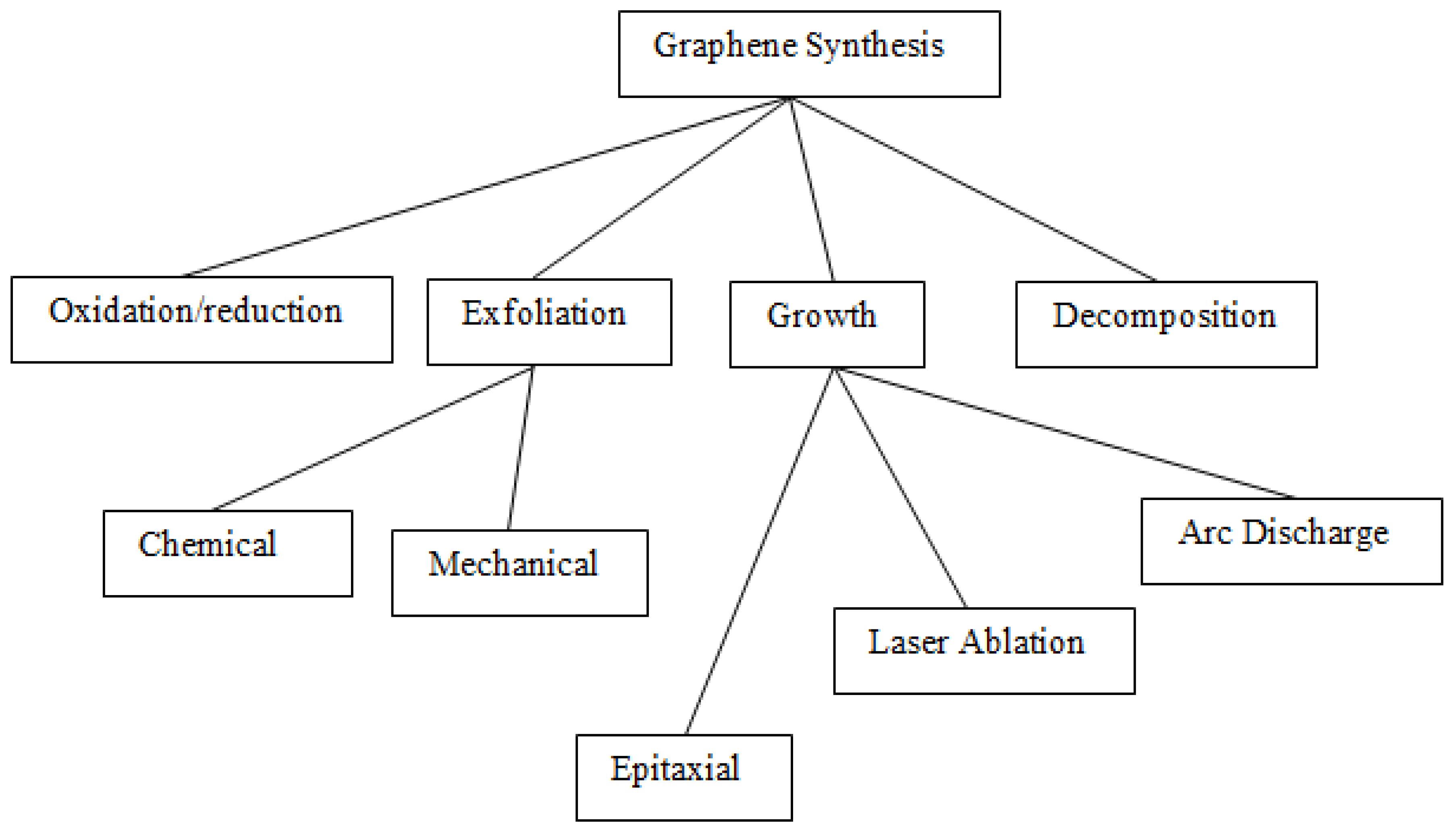
7. Synthesis of Metal Oxide Nanoparticles

Various chemical, physical and biological methods have been employed for the synthesis of metal oxide nanoparticles [99]. They can be categorized into bottom-up (biological and chemical processes) and top-down (physical methods) [100]. The top-down or destructive approach involves decomposing bulk material into smaller units, followed by conversion to desired nanoscaled particles [101]. The approach comprises various decomposition methods like physical vapor deposition, grinding, pulsed laser ablation, and ball milling. In a bottom-up or constructive approach, the atoms or small molecular precursors are built up to form nanoparticles after the nucleation process. Electrospinning, sol-gel, hydrothermal, microemulsion, co-precipitation, electrochemical, thermal decomposition, and biological methods are bottom-up approaches.
The commonly used methods for TiO2, Fe3O4, ZnO based nanoparticles are sol-gel, micro-emulsion, electrochemical method, thermal decomposition, biological synthesis, and several other procedures. Despite the utilization of several methods used for nanoparticle fabrication, co-precipitation is the more effective, more practical, cheap, and most universal method for nanoparticle growth [102]. Thorough tuning of pH, precursor-co-precipitant ratio, temperature, and agitation rate may readily result in well-shaped, sized, phased, and scalable nanoparticles. TiO2, Fe3O4, and ZnO particles have extensively used toxic metal (Cu, Zn, Cr, Cd, Fe, Pb) adsorption from simulated wastewater [103]. The metal oxide nanoparticle’s uptake efficiency is highly dependent on a surface charge, size, surface area, catalytic strength, available adsorption points, and the shape of the adsorbent [104,105,106]. Similarly, these findings have been almost consistent with the synthesized adsorptive nanoparticles for wastewater remediation [93]. Since the metal oxide property change is highly dependent on synthetic steps, there are advantages, influencing aspects, merit, and demerit associated with the method, as summarized in Table 4 and Table 5.
The synthesis of graphene is grouped into two main method categories, i.e., the direct and indirect methods (Figure 1). In the direct methods, the graphene is directly developed on the substrate surface via the steps that utilize a solid carbon mother source. The indirect procedures involve depositing carbon sheets on the substrate surface, followed by conversion to graphene through the energy post-treatment process.
Various methods for graphene synthesis have been established, such as liquid-phase exfoliation, mechanical exfoliation and cleavage, thermal decomposition, electrochemical process, oxidation/reduction, and a few other procedures [107,108]. The synthesis method and carbon source type constitute various categories for graphene synthesis. Graphene may be surfaced on the single-crystal transition metal via laser ablation, chemical vapor deposition (CVD), spin coating, and physical vapor deposition (PVD). The PVD is preferred over CVD due to the achievement of low-temperature use, high yield, and manageable graphene growth on multiple substrate surfaces. In contrast, the CVD method is reported to have sensitive deposition conditions such as growth time, gas concentration, substrate surface, and temperature [109].
The PVD of graphene may be accomplished via ion plating, sputtering, ion beam-assisted growth, and vacuum evaporation [109]. Furthermore, the PVD graphene synthesis can be achieved through direct (growth by utilizing significant energy carbon source and the transitional metallic substrate) and indirect method (deposition through energetic post-growth treatment for amorphous carbon film conversion to graphene structure).
Direct graphene growth involves high-temperature vacuum evaporation of graphite through high-energy treatment. This results in the controlled growth on transitional metal or alloy substrate surface connected to the process chamber cathode. The method set includes arc discharge, laser, unzipping carbon nanotubes, etching, and chemical and mechanical exfoliation [109]. In these methods, the carbon source may be fullerene, graphite, amorphous carbon film, and carbon nanotubes. The evaporation potential can be sourced from ablation, arc discharge, and pulsed laser deposition [110]. However, modeling the deposition conditions for graphene fabrication may be moderately hard and more significant.
The fabrication of graphene is achieved from liquid, gaseous, and carbonaceous precursors. Furthermore, the method involves atom/molecule decomposition from suitable precursors followed by an in-situ arrangement to generate the hexagonal graphene structural sheet/s [111]. Some methods are epitaxial growth, chemical vapor deposition (CVD), and pyrolysis. It is documented that crystallized amorphous carbon (possibly in-housing small impurities and crystal defects) exhibits thermodynamical instability compared to the graphite carbon source (ΔG < 0 for amorphous carbon to graphite change and kinetically stable resulting in slow transformation-to-graphene rate). Due to the atomic structuring in both 2D and 3D irregular and multiple bonded structures, a phase transformation initialized from amorphous to crystallized carbon needs high temperature and pressure. The challenge is that a small amorphous carbon fraction may be converted into graphite. As a result, the transitional metal substrate has been put in place for graphene deposition via low pressure and temperature use [112].

7.1. Direct methods

7.1.1. Arc Discharge

This is accomplished by passing a direct current between high purity graphite electrode pair on the inert gas environment at ~500 torr and has been employed for the fabrication of carbon nanomaterials (e.g., carbon nanotubes (CNTs), graphene, fullerenes (C60)), metal/metal oxide nanoparticles [113]. The inexpensive synthesis of a few sheets of graphene has been achieved through this method aided by multiple uses of buffer gases (such as hydrogen (H2), argon (Ar), and helium (He)) which help in bond breakage existing between the carbon layers, resulting into combatting the graphitic layer closing and roll up condition. Additionally, the mixed H2/He treatment’s merit helped yield a large surface area and high crystalline graphene [114]. However, the limitation associated with the method is the use of high pressure/chamber temperature, which may suffer stacked and aggregated graphene products [115].

7.1.2. Laser Procedures

The techniques used in graphene synthesis through laser methods are pulsed laser deposition and laser ablation. The laser exfoliation may be employed to catalyze halogen removal from the graphene surface, followed by a detachment of the graphene sheet portion [109]. The carbon materials are generated on the irradiated graphitic surface during the laser ablation. Ultraviolet light may be used for peeling and direct deposition of graphene nanolayer/s onto the substrate with no need for catalyst use. Furthermore, the graphene synthesis may be achieved under room conditions, but in most cases tuning of processing parameters (applied pressure, focal length, substrate distance, laser ablation volume, and energy) may be fairly complex but more significant for graphene synthesis [116].

7.1.3. Pulsed Laser Method

Pulsed laser deposition (PLD) is one of the physical vapor deposition methods for graphene growth by graphite target irradiation in a vacuum using the transitional metal substrate [117]. The process involves direct graphene growth on the substrate at high temperatures without the carbide generation at the metal-graphene face. Multiple steps involved during graphene growth are carbon atom adsorption, precipitation, segregation, recrystallization, and these processes occur because of transitional metal and carbon atom interaction [118]. The parameters influencing the graphene growth quality, such as thickness and layer number, are laser wavelength, fluence, pulse duration, and repetition rate. Secondly, the background pressure, vacuum level, substrate distance, and temperature are influential parameters during the synthesis [119]. In this method, the laser is situated outside of the vacuum, thus enabling the synthesis under ambient conditions, and using an ultrahigh vacuum. The advantages of the PLD method are better adhesion to the substrate, low processing temperature, and reasonable growth rate.

7.1.4. Reduction of Graphene Oxide

The preparation of a large yield of few-layer graphene has been achieved through graphene oxide reduction [120]. In a specific procedure, the graphite oxide has been synthesized through oxidative treatment of graphite by using oxidants such as nitric acid, potassium permanganate, and sulfuric acid, commonly through the simple Hummers method. This process is followed by the reduction phase whereby reducing agents such as pyrrole, hydroxylamine, ascorbic acid, phenylhydrazine, hydroquinone, glucose, and sodium borohydride have been used to reduce the oxygen content of the graphene oxide and thus, successful reduction leading to few-layer pristine graphene [121]. The restoration of graphene’s unique sp2 hybridized property is also enhanced by H2 addition, which takes place across the alkenes, calcination under nitrogen/argon gas. The method is time-consuming, requires thorough washing, and uses strong oxidizing and reducing chemicals.

7.1.5. Mechanical Exfoliation

The method involves the transference of kinetic potential to the bulk material, resulting in micro-size and nanoscaled size generation. Several studies on graphene fabrication using mechanical exfoliation for achieving a series of graphene thickness, surface area, thermal properties, and others have been documented using highly ordered pyrolytic graphite, natural graphite, and monocrystal graphite [120,122]. Some literature refers to micromechanical cleavage as a scotch tape procedure. This is well known since the graphene sheet’s bonding strength to an adhesive tape was employed to counteract the effect of the weak van de Waals forces in graphite molecule. Cutting the graphite (carbon source) into mono-to-few sheets can be achieved via both room and high temperatures. However, the method requires an applied force of up to 300 nN/µm2 to transition into successful mono-atomic sheet separation from graphitic material [123]. Further notable limitations are the method’s inability for scalability (low throughput) and reproducibility [124].

7.1.6. Chemical and Electrochemical Exfoliation

The exfoliations of the graphite to graphene include reduction of the van de Waals forces (~ 61 meV per C atom) between graphite, thus resulting in gradual interlayer spacing. Briefly, the exfoliation through an ultrasonicated liquid phase and electrochemical set up is based on the large-sized molecule or metallic atom intercalation/insertion within the graphite sheets or via chemical oxidation. The ultrasonication uses waves that have rarefaction and compression cycles. Moreover, the cavitation occurs in the rarefaction phase, whereby negative acoustic pressure is high to disintegrate the liquid forming transient/stable microbubbles. The cavitation also involves the generation and vigorous collapse of the bubble within a short period, with a temperature of up to 5000 K, a heating/cooling rate of up to 109 K s−1, and pressure of up to 20 MPa [125]. The process also produces shock waves and hydromechanical forces, which contribute to breaking graphitic bonds. However, the edge defects sourced from cavitation and long sonication period may result in oxygenated graphene edges if sometimes the exfoliation is performed in the air [126].
Due to interlayer spacing and weak van der Waals forces, sonication in different pure solvents and surfactant-assisted solvents have been employed for graphite exfoliation outputting suitable single to few-layer graphene. The yield and quality of the product (lateral size, layer number) depend on sonication time, power, temperature, frequency, and solvent choice [127].
The solvent choice is key to the graphite’s liquid phase exfoliation (LPE). It has been documented that solvent mainly affects the graphene colloidal suspension stability and amount. Consequently, the exfoliation depends on the solvent surface tension, and the study showed that 40–50 mJ/m2 surface tension values tend to output good exfoliation [128]. Secondly, the solvent should overpower the weak forces between graphene sheets, of which these sheets are suspended within the π–π stacking length of 3.35–3.4 Å [120]. Thirdly, to achieve suspension stability, the nanolayer-solvent interactions must balance the interlayer attractive forces [129]. The LPE has been regarded as an efficient graphene synthesis method; interestingly, water can be used in the process. However, surfactant-water-assisted sonication has also been well studied for the betterment of dispersion, exfoliation, layer quality, and yield [130].
The documentation shows a linear proportional growth between the exfoliated graphene layer amount and the applied sonication energy, temperature, power, and frequency [127]. Furthermore, these parameters have shown the potential to produce a few graphene layers [131]. Several studies have been conducted to confirm their effects. However, some studies proved an indirectly proportional relationship between the sonication time and the abovementioned parameters in producing better mono to few-layer graphene.

7.2. Indirect Methods

7.2.1. Epitaxial Growth

Epitaxial graphene growth involves the decomposition of SiC under high temperatures in an ultra-high vacuum. The Si is vaporized, resulting in a carbon-rich surface in graphene layer form on the substrate top surface [122]. Moreover, post the interface layer generation, the Si may be sublimated by the step edges (resulting in horizontal or in-plane diffusion) or through interlayer defects (resulting in vertical diffusion). Four critical steps of epitaxial graphene growth, (a) the interlayer production, (b) graphene sheet growth at step edges, and (c) graphitization (where the step flow front forms toward terraces center, whereas the flakes combine and thus resulting in increased domain sizes), (d) post-formation of the first monolayer graphene then the Si may diffuse via step edges or defects to generate another layer (bilayer) [122]. The epitaxial growth is partitioned into hetero-epitaxial (the film deposited on the substrate surface is sourced from various materials) and homo-epitaxial growth (the substrate and film are of the same material). This study showed the growth of three few-layered graphenes on single crystalline 6H-SiC, and it was also found that the graphene growth rate on SiC substrate was mainly dependent on a particular SiC crystal face. A further discovery was that graphene growth was slower on the Si-face than on the C-face via thermal decomposition of SiC greater than 1000 °C [132]. Consequently, epitaxial growth on SiC substrate has been regarded as a vital method for the large-scale generation of graphene.

7.2.2. Chemical Vapour Deposition (CVD)

During the CVD, suitable graphene precursors are deposited on the substrate surface via pyrolytic decomposition, thus resulting in deposition sites on the substrate surface and subsequent layer deposition [133]. The method is regarded as an effective procedure for generating better quality graphene with high throughput and the capability to yield large area mono crystal graphene [134]. In this method, the resultant toxic by-products are eliminated from the reaction body via flow gas, enabling proper disposal. Despite the merits of CVD, the limitations are: the employed precursors should be readily volatile for deposition on the substrate surface, expensiveness, and consumption of high substrate amount to achieve large throughput of the graphene sheet [135].

7.2.3. Carbon Nanotube (CNT)

CNTs are cylindrical macromaterial composed of hexagonal lattice carbon atom arrangement forming a tube-like structure [115]. The carbon atom hybridization in the CNT sheet results in two types of CNTs: single-wall carbon nanotubes (SWCNT) and multi-wall carbon nanotubes (MWCNTs). The SWCNT can be seen as a cylindrically rolled single graphene sheet with a diameter of 1 to 3 nm. In contrast, the MWCNTs (1 to 100 nm) are composed of several diametric SWCNTs compressed together, forming multi-layered and rolled graphene sheets [136]. Carbon can create geometrical structuring through its binding strength for the generation of long-chain and branched molecules. CNTs possess good properties like ultra-light mass, thermal stability, surface area, mechanical strength, and thermal stability [137]. Due to the CNTs’ exceptional properties, the material has stretched application in supporting agents in hybrid nanocomposite material, biosensors, and fuel cells [138]. The CNTs’ porous nature and high specific surface area have made several study explorations on CNTs for remediation of organic, microbes, and inorganic water pollutants. Since its discovery in 1991, the configured CNTs have attracted research studies for Cr, Fe, Cu, Pb, Cd, and Zn removal in simulated and real wastewater by adsorption mechanism [139].
To achieve CNTs’ optimum performance, several synthesis methods have been employed. Some are common to the graphene synthesis method previously covered in this review. The methods are electric arc discharge, laser ablation, chemical vapor deposition, vapor phase growth, thermal synthesis, and flame synthesis [140].
Vapour phase growth is a modified and more developed version of the chemical vapor deposition method. The method has a ferrocene catalyst and two furnaces in the reaction chamber with low-temperature values. Additionally, the catalytic particles are generated at furnace one, and their transition to furnace two, the carbon is transported in catalyst via diffusion resulting in CNTs formation [139]. Generally, the CNTs are formed in a reaction chamber with substrate absence and catalytic transitional metal presence. The flame synthesis CNTs method uses the flame as heat energy and nano atom sources. The injection of gaseous catalyst species may functionalize the flame. This method involves heating fuel species in an ambient environment to yield radicals, H2O vapors, C2H2, C2H6, H2, CO, and CO2 [141]. The CNTs growth is similar to the chemical vapor deposition technique. High-temperature use and high costliness are limitations.
Another method for CNTs synthesis is thermal synthesis. The process involves a steady heat supply which is preferably below 1200 °C. The operation is almost the same as the chemical vapor deposition but depends on the precursors used in forming CNTs. Transitional metals such as nickel and iron are used as a catalyst in this process [142].
Common synthesis of the CNTs is associated with chemical vapor deposition, laser ablation, and arc discharge [143]. Catalyst precursor and non-catalyzed arc discharge method may be used for CNTs synthesis. Typically, the non-catalyzed synthesis favors MWCNTs, while the catalyst-assisted method suits SWCNTs sourced from metals, graphite, and metal alloys under an inert gas environment [123]. The advantages associated with the methods are better diameter size (<25 nm), larger surface area, and production yield (~99%) with high-purity CNTs. However, the presented disadvantages are high energy consumption, difficult control over the process, tangled CNTs, and low production rate [142].

8. Conclusions

Portable water provision from the heavily polluted industrial wastewater is one of the most critical priorities of the current generation. Applying suitable adsorbents in wastewater treatment has proved very efficient and economical. The current review provided an overview of adsorption processes for contaminant removal. This includes a discussion of the important conventional and non-conventional adsorbents used to remove toxic pollutants from wastewater. The non-conventional adsorbents offer comparative advantages in cost-effectiveness and efficiency.
Likewise, a summary of the development of traditional and nano-advanced adsorbents has been provided in the current review. Various methods have individual significance and drawbacks on material synthesis, affecting the adsorbent performance on metal removal. Thus, moderate adjustments and optimizations are necessary for inexpensive, eco-friendly adsorbent growth. The adsorption process is also affected by material porosity, surface area, affinitive functional group sites, adsorbate-adsorbent interaction, solution pH, ionic strength, adsorbent dosage, and temperature. Furthermore, the adsorption isotherm and kinetic models are vital for the improved adsorption design and monitoring of mono and multilayer adsorption systems. The traditional materials also present a capability for metal uptake in an aqueous environment. The preservation of the small size, surface area, morphology, and magnetic properties of nanomaterials could afford the adsorbent regeneration and reuse. Carbon-based composite material exhibits better adsorption capacities due to their possible functionalization and robustness and offer multiple binding sites for physical or chemical adsorption of the metal species. Likewise, Bio sorbent is an excellent adsorbent with the capability for nonselective toxic metal uptake from the complex matrix. Its cost-effectiveness is a turning point in sorption technology. Besides, it is regeneratable, readily available, and produces near zero quantity of sludge. The application of biosorbents as green technology is therefore essential for the enhancement of the process of wastewater remediation using sorption technology.

Funding

This research was funded by National Research Foundation (NRF), South Africa, grant number: 120375 and Tertiary Education Support Program (TESP), Eskom Holdings SOC Limited Reg No 2002/015527/0.

Data Availability Statement

Not applicable.

Conflicts of Interest

The authors declare no conflict of interest.

References

  1. Sharma, M.; Kalita, P.; Senapati, K. Study on Magnetic Materials for Removal of Water Pollutants. In Emerging Pollutants-Some Strategies for the Quality Preservation of Our Environment; BoD—Books on Demand: Norderstedt, Germany, 2018; pp. 221–244. [Google Scholar]
  2. Azimi, A.; Azari, A.; Rezakazemi, M.; Ansarpour, M. Removal of Heavy Metals from Industrial Wastewaters: A Review. ChemBioEng Rev. 2017, 4, 37–59. [Google Scholar] [CrossRef]
  3. Barakat, M.A. New trends in removing heavy metals from industrial wastewater. Arab. J. Chem. 2011, 4, 361–377. [Google Scholar] [CrossRef]
  4. Fu, F.; Wang, Q. Removal of heavy metal ions from wastewaters: A review. J. Environ. Manag. 2011, 92, 407–418. [Google Scholar] [CrossRef] [PubMed]
  5. Periyasamy, S.; Kumar, I.A.; Viswanathan, N. Activated Carbon from Different Waste Materials for the Removal of Toxic Metals. Green Mater. Wastewater Treat. 2020, 38, 47–68. [Google Scholar] [CrossRef]
  6. Alloway, B.J. Sources of Heavy Metals and Metalloids in Soils. In Heavy Metals in Soils; Springer: Dordrecht, The Netherlands, 2013; pp. 11–50. [Google Scholar] [CrossRef]
  7. Uddin, M.K. A review on the adsorption of heavy metals by clay minerals, with special focus on the past decade. Chem. Eng. J. 2017, 308, 438–462. [Google Scholar] [CrossRef]
  8. Sankaran, R.; Show, P.L.; Ooi, C.-W.; Ling, T.C.; Shu-Jen, C.; Chen, S.-Y.; Chang, Y.-K. Feasibility assessment of removal of heavy metals and soluble microbial products from aqueous solutions using eggshell wastes. Clean Technol. Environ. Policy 2020, 22, 773–786. [Google Scholar] [CrossRef]
  9. Sachan, D.; Ramesh, A.; Das, G. Green synthesis of silica nanoparticles from leaf biomass and its application to remove heavy metals from synthetic wastewater: A comparative analysis. Environ. Nanotechnol. Monit. Manag. 2021, 16, 100467. [Google Scholar] [CrossRef]
  10. Sharma, R.K.; Solanki, K.; Dixit, R.; Sharma, S.; Dutta, S. Nanoengineered iron oxide-based sorbents for separation of various water pollutants: Current status, opportunities and future outlook. Environ. Sci. Water Res. Technol. 2021, 7, 818–860. [Google Scholar] [CrossRef]
  11. Abdullah, N.; Yusof, N.; Lau, W.J.; Jaafar, J.; Ismail, A.F. Recent trends of heavy metal removal from water/wastewater by membrane technologies. J. Ind. Eng. Chem. 2019, 76, 17–38. [Google Scholar] [CrossRef]
  12. Zamora-Ledezma, C.; Negrete-Bolagay, D.; Figueroa, F.; Zamora-Ledezma, E.; Ni, M.; Alexis, F.; Guerrero, V.H. Heavy metal water pollution: A fresh look about hazards, novel and conventional remediation methods. Environ. Technol. Innov. 2021, 22, 101504. [Google Scholar] [CrossRef]
  13. Chai, W.S.; Cheun, J.Y.; Kumar, P.S.; Mubashir, M.; Majeed, Z.; Banat, F.; Ho, S.H.; Show, P.L. A review on conventional and novel materials towards heavy metal adsorption in wastewater treatment application. J. Clean. Prod. 2021, 296, 126589. [Google Scholar] [CrossRef]
  14. Qu, J. Research progress of novel adsorption processes in water purification: A review. J. Environ. Sci. 2008, 20, 1–13. [Google Scholar] [CrossRef]
  15. Jawed, A.; Saxena, V.; Pandey, L.M. Engineered nanomaterials and their surface functionalization for the removal of heavy metals: A review. J. Water Process. Eng. 2020, 33, 101009. [Google Scholar] [CrossRef]
  16. Fato, F.P.; Li, D.-W.; Zhao, L.-J.; Qiu, K.; Long, Y.-T. Simultaneous Removal of Multiple Heavy Metal Ions from River Water Using Ultrafine Mesoporous Magnetite Nanoparticles. ACS Omega 2019, 4, 7543–7549. [Google Scholar] [CrossRef]
  17. Tripathi, A.; Rawat Ranjan, M. Heavy Metal Removal from Wastewater Using Low Cost Adsorbents. J. Bioremediat. Biodegrad. 2015, 6, 315. [Google Scholar] [CrossRef]
  18. Al-Ghouti, M.A.; Da’ana, D.A. Guidelines for the use and interpretation of adsorption isotherm models: A review. J. Hazard. Mater. 2020, 393, 122383. [Google Scholar] [CrossRef]
  19. Agboola, O.D.; Benson, N.U. Physisorption and Chemisorption Mechanisms Influencing Micro (Nano) Plastics-Organic Chemical Contaminants Interactions: A Review. Front. Environ. Sci. 2021, 167. [Google Scholar] [CrossRef]
  20. Tamiru, M.; Bekele, G. International Journal of Water and Wastewater Treatment Various Absorbents and Parameters Affecting Removal of Water Hardness from Wastewater: Review. Int. J. Water Wastewater Treat. 2020, 6, 173. [Google Scholar] [CrossRef]
  21. De Freitas, G.R.; da Silva, M.G.C.; Vieira, M.G.A. Biosorption technology for removal of toxic metals: A review of commercial biosorbents and patents. Environ. Sci. Pollut. Res. 2019, 26, 19097–19118. [Google Scholar] [CrossRef]
  22. Ugwu, E.I.; Tursunov, O.; Kodirov, D.; Shaker, L.M.; Al-Amiery, A.A.; Yangibaeva, I.; Shavkarov, F. Adsorption mechanisms for heavy metal removal using low cost adsorbents: A review. IOP Conf. Ser. Earth Environ. Sci. 2020, 614, 012166. [Google Scholar] [CrossRef]
  23. Gupta, A.; Sharma, V.; Sharma, K.; Kumar, V.; Choudhary, S.; Mankotia, P.; Kumar, B.; Mishra, H.; Moulick, A.; Ekielski, A.; et al. A Review of Adsorbents for Heavy Metal Decontamination: Growing Approach to Wastewater Treatment. Materials 2021, 14, 4702. [Google Scholar] [CrossRef] [PubMed]
  24. Vo, T.S.; Hossain, M.M.; Jeong, H.M.; Kim, K. Heavy metal removal applications using adsorptive membranes. Nano Converg. 2020, 7, 36. [Google Scholar] [CrossRef] [PubMed]
  25. Zand, A.D.; Abyaneh, M.R. Adsorption of Lead, manganese, and copper onto biochar in landfill leachate: Implication of non-linear regression analysis. Sustain. Environ. Res. 2020, 30, 18. [Google Scholar] [CrossRef]
  26. Burakov, A.E.; Galunin, E.V.; Burakova, I.V.; Kucherova, A.E.; Agarwal, S.; Tkachev, A.G.; Gupta, V.K. Adsorption of heavy metals on conventional and nanostructured materials for wastewater treatment purposes: A review. Ecotoxicol. Environ. Saf. 2018, 148, 702–712. [Google Scholar] [CrossRef]
  27. Crini, G.; Lichtfouse, E.; Wilson, L.D.; Morin-Crini, N. Conventional and non-conventional adsorbents for wastewater treatment. Environ. Chem. Lett. 2019, 17, 195–213. [Google Scholar] [CrossRef]
  28. Bushra, R.; Shahadat, M.; Ahmad, A.; Nabi, S.A.; Umar, K.; Oves, M.; Raeissi, A.S.; Muneer, M. Synthesis, characterization, antimicrobial activity and applications of polyanilineTi(IV)arsenophosphate adsorbent for the analysis of organic and inorganic pollutants. J. Hazard. Mater. 2014, 264, 481–489. [Google Scholar] [CrossRef]
  29. Ayranci, E.; Duman, O. In-Situ UV-Visible Spectroscopic Study on the Adsorption of some Dyes onto Activated Carbon Cloth. Sep. Sci. Technol. 2009, 44, 3735–3752. [Google Scholar] [CrossRef]
  30. Deliyanni, E.A.; Kyzas, G.Z.; Triantafyllidis, K.S.; Matis, K.A. Activated carbons for the removal of heavy metalions: A systematic review of recent literaturefocused on lead and arsenic ion. Open Chem. 2015, 13, 699–708. [Google Scholar]
  31. Shehzad, A.; Bashir, M.J.K.; Sethupathi, S.; Lim, J.W. An overview of heavily polluted landfill leachate treatment using food waste as an alternative and renewable source of activated carbon. Process. Saf. Environ. Prot. 2015, 98, 309–318. [Google Scholar] [CrossRef]
  32. Heidarinejad, Z.; Dehghani, M.H.; Heidari, M.; Javedan, G.; Ali, I.; Sillanpää, M. Methods for preparation and activation of activated carbon: A review. Environ. Chem. Lett. 2020, 18, 393–415. [Google Scholar] [CrossRef]
  33. Nabais, J.V.; Carrott, P.; Ribeiro Carrott, M.M.L.; Luz, V.; Ortiz, A.L. Influence of preparation conditions in the textural and chemical properties of activated carbons from a novel biomass precursor: The coffee endocarp. Bioresour. Technol. 2008, 99, 7224–7231. [Google Scholar] [CrossRef]
  34. Deng, H.; Yang, L.; Tao, G.; Dai, J. Preparation and characterization of activated carbon from cotton stalk by microwave assisted chemical activation—Application in methylene blue adsorption from aqueous solution. J. Hazard. Mater. 2009, 166, 1514–1521. [Google Scholar] [CrossRef]
  35. Tran, H.N.; Chao, H.P.; You, S.J. Activated carbons from golden shower upon different chemical activation methods: Synthesis and characterizations. Adsorpt. Sci. Technol. 2017, 36, 95–113. [Google Scholar] [CrossRef]
  36. Gao, Y.; Yue, Q.; Gao, B.; Li, A. Insight into activated carbon from different kinds of chemical activating agents: A review. Sci. Total Environ. 2020, 746, 141094. [Google Scholar] [CrossRef]
  37. Salman, S.; Rasheed, I.; Mohammed, A. IOP Conference Series: Earth and Environmental Science. IOP Conf. Ser. Earth Environ. Sci. 2021, 779, 012074. [Google Scholar] [CrossRef]
  38. Gebretsadik, H.; Gebrekidan, A.; Demlie, L. Removal of heavy metals from aqueous solutions using Eucalyptus Camaldulensis: An alternate low cost adsorbent. Cogent Chem. 2020, 6, 1720892. [Google Scholar] [CrossRef]
  39. Rashed, M.; Soltan, M.; Ahmed, M.; Abdou, A. Heavy Metals Removal from Wastewater by Adsorption on Modified Physically Activated Sewage Sludge. Arch. Org. Inorg. Chem. Sci. 2018, 1, 1–8. [Google Scholar] [CrossRef]
  40. Ibrahim, W.M.; Hassan, A.F.; Azab, Y.A. Biosorption of toxic heavy metals from aqueous solution by Ulva lactuca activated carbon. Egypt. J. Basic Appl. Sci. 2019, 3, 241–249. [Google Scholar] [CrossRef]
  41. Hernández-Montoya, V.; García-Servin, J.; Bueno-López, J.I. Thermal Treatments and Activation Procedures Used in the Preparation of Activated Carbons. In Lignocellulosic Precursors Used in the Synthesis of Activated Carbon-Characterization Techniques and Applications in the Wastewater Treatment; BoD—Books on Demand: Norderstedt, Germany, 2012; pp. 19–36. [Google Scholar]
  42. Tasić, Ž.Z.; Bogdanović, G.D.; Antonijević, M.M. Application of natural zeolite in wastewater treatment: A review. J. Min. Metall. A Min. 2019, 55, 67–79. [Google Scholar] [CrossRef]
  43. Salih, A.M. The Purification of Industrial Wastewater to Remove Heavy Metals and Investigation into the Use of Zeolite as a Remediation Tool; University of Wolverhampton: Wolverhampton, UK, 2017. [Google Scholar]
  44. Turksoy, R.; Terzioglu, G.; Ertugrul Yalcin, I.; Turksoy Terzioglu, O.; Demir, G. Removal of heavy metals from textile industry wastewater. Front. Life Sci. Relat. Technol. 2021, 2, 44–50. [Google Scholar] [CrossRef]
  45. Taamneh, Y.; Sharadqah, S. The removal of heavy metals from aqueous solution using natural Jordanian zeolite. Appl. Water Sci. 2017, 7, 2021–2028. [Google Scholar] [CrossRef]
  46. Gülen, J.; Zorbay, F.; Arslan, S. Zeolites and their uses. Karaelmas J. Sci. Eng. 2012, 2, 63–68. [Google Scholar]
  47. Yuna, Z. Review of the natural, modified, and synthetic zeolites for heavy metals removal from wastewater. Environ. Eng. Sci. 2016, 33, 443–454. [Google Scholar] [CrossRef]
  48. La Vega, D.P.D.; González, C.; Escalante, C.A.; Gallego, J.; Salamanca, M.; Manrique-Losada, L. Use of faujasite-type zeolite for ion adsorption in municipal wastewater. Tecnol. Cienc. Agua 2018, 9, 184–208. [Google Scholar] [CrossRef]
  49. Iqra, J.; Faryal, M.; Uzaira, R.; Noshaba, T. Preparation of zeolite from incinerator ash and its application for the remediation of selected inorganic pollutants: A greener approach. IOP Conf. Ser. Mater. Sci. Eng. 2014, 60, 012060. [Google Scholar] [CrossRef]
  50. Hanane, B.; Seyd Abdelkader, H.; Kromia, M.; Salah, A.M. Removal of Heavy Metals from an Industrial Effluent by Synthesized Zeolite: Case of Bounoura Industrial Zone. Leban. Sci. J. 2020, 21, 80–94. [Google Scholar] [CrossRef]
  51. Ismail, A.I.M.; El-Shafey, O.I.; Amr, M.H.A.; El-Maghraby, M.S. Pumice Characteristics and Their Utilization on the Synthesis of Mesoporous Minerals and on the Removal of Heavy Metals. Int. Sch. Res. Not. 2014, 2014, 259379. [Google Scholar] [CrossRef]
  52. Wołowicz, A.; Wawrzkiewicz, M. Screening of Ion Exchange Resins for Hazardous Ni(II) Removal from Aqueous Solutions: Kinetic and Equilibrium Batch Adsorption Method. Processes 2021, 9, 285. [Google Scholar] [CrossRef]
  53. Gu, S.; Kang, X.; Wang, L.; Lichtfouse, E.; Wang, C. Clay mineral adsorbents for heavy metal removal from wastewater: A review. Environ. Chem. Lett. 2018, 17, 629–654. [Google Scholar] [CrossRef]
  54. Tripathi, A.K.; Upadhyay, S.; Bhuiyan, M.; Bhattacharya, P.R. A review on prospects of essential oils as biopesticide in insect-pest management. J. Pharmacogn. Phyther. 2009, 1, 52–63. Available online: http://www.academicjournals.org/jpp (accessed on 10 July 2022).
  55. Nakato, T.; Miyamoto, N. Liquid Crystalline Behavior and Related Properties of Colloidal Systems of Inorganic Oxide Nanosheets. Materials 2009, 2, 1734–1761. [Google Scholar] [CrossRef]
  56. Ayalew, A.A. A critical review on clay-based nanocomposite particles for application of wastewater treatment. Water Sci. Technol. 2022, 85, 3002–3022. [Google Scholar] [CrossRef]
  57. Bhattacharyya, K.G.; Gupta, S. Sen Adsorption of a few heavy metals on natural and modified kaolinite and montmorillonite: A review. Adv. Colloid Interface Sci. 2008, 140, 114–131. [Google Scholar] [CrossRef]
  58. Heller-Kallai, L. Thermally Modified Clay Minerals. Dev. Clay Sci. 2006, 1, 289–308. [Google Scholar] [CrossRef]
  59. Barakan, S.; Aghazadeh, V. The advantages of clay mineral modification methods for enhancing adsorption efficiency in wastewater treatment: A review. Environ. Sci. Pollut. Res. 2020, 28, 2572–2599. [Google Scholar] [CrossRef]
  60. El Mouzdahir, Y.; Elmchaouri, A.; Mahboub, R.; Gil, A.; Korili, S.A. Equilibrium modeling for the adsorption of methylene blue from aqueous solutions on activated clay minerals. Desalination 2010, 250, 335–338. [Google Scholar] [CrossRef]
  61. Akar, S.T.; Yetimoglu, Y.; Gedikbey, T. Removal of chromium (VI) ions from aqueous solutions by using Turkish montmorillonite clay: Effect of activation and modification. Desalination 2009, 244, 97–108. [Google Scholar] [CrossRef]
  62. Shawabkeh, A.; Al-Khashman, O.; Al-Omari, H.; Shawabkeh, A. Cobalt and zinc removal from aqueous solution by chemically treated bentonite. Environmentalist 2007, 27, 357. [Google Scholar] [CrossRef]
  63. Komadel, P.; Madejová, J. Acid Activation of Clay Minerals. Dev. Clay Sci. 2013, 5, 385–409. [Google Scholar] [CrossRef]
  64. Borji, H.; Ayoub, G.M.; Bilbeisi, R.; Nassar, N.; Malaeb, L. How Effective Are Nanomaterials for the Removal of Heavy Metals from Water and Wastewater? Water Air Soil Pollut. 2020, 231, 330. [Google Scholar] [CrossRef]
  65. Sinha Ray, S.; Okamoto, M. Polymer/layered silicate nanocomposites: A review from preparation to processing. Prog. Polym. Sci. 2003, 28, 1539–1641. [Google Scholar] [CrossRef]
  66. Bhati, M.; Rai, R. Nanotechnology and water purification: Indian know-how and challenges. Environ. Sci. Pollut. Res. 2017, 24, 23423–23435. [Google Scholar] [CrossRef]
  67. Kolluru, S.S.; Agarwal, S.; Sireesha, S.; Sreedhar, I.; Kale, S.R. Heavy metal removal from wastewater using nanomaterials-process and engineering aspects. Process. Saf. Environ. Prot. 2021, 150, 323–355. [Google Scholar] [CrossRef]
  68. Liosis, C.; Papadopoulou, A.; Karvelas, E.; Karakasidis, T.E.; Sarris, I.E. Heavy Metal Adsorption Using Magnetic Nanoparticles for Water Purification: A Critical Review. Materials 2021, 14, 7500. [Google Scholar] [CrossRef]
  69. Saharan, P.; Chaudhary, G.R.; Mehta, S.K.; Umar, A. Removal of water contaminants by iron oxide nanomaterials. J. Nanosci. Nanotechnol. 2014, 14, 627–643. [Google Scholar] [CrossRef]
  70. Tsedenbal, B.; Lee, J.E.; Huh, S.H.; Koo, B.H.; Lee, C.G. Removal of Heavy Metals from Wastewater using α-Fe2O3 Nanocrystals. Korean J. Mater. Res. 2020, 30, 447–452. [Google Scholar] [CrossRef]
  71. Jiang, W.; Pelaez, M.; Dionysiou, D.D.; Entezari, M.H.; Tsoutsou, D.; O’Shea, K. Chromium(VI) removal by maghemite nanoparticles. Chem. Eng. J. 2013, 222, 527–533. [Google Scholar] [CrossRef]
  72. Parvin, F.; Rikta, S.Y.; Tareq, S.M. Application of Nanomaterials for the Removal of Heavy Metal from Wastewater. In Nanotechnology in Water and Wastewater Treatment: Theory and Applications; Elsevier: Amsterdam, The Netherlands, 2019; pp. 137–157. [Google Scholar]
  73. Tamjidi, S.; Esmaeili, H.; Moghadas, B.K. Application of magnetic adsorbents for removal of heavy metals from wastewater: A review study. Mater. Res. Express 2019, 6, 102004. [Google Scholar] [CrossRef]
  74. Vojoudi, H.; Badiei, A.; Bahar, S.; Mohammadi Ziarani, G.; Faridbod, F.; Ganjali, M.R. A new nano-sorbent for fast and efficient removal of heavy metals from aqueous solutions based on modification of magnetic mesoporous silica nanospheres. J. Magn. Magn. Mater. 2017, 441, 193–203. [Google Scholar] [CrossRef]
  75. Lingamdinne, L.P.; Chang, Y.Y.; Yang, J.K.; Singh, J.; Choi, E.H.; Shiratani, M.; Koduru, J.R.; Attri, P. Biogenic reductive preparation of magnetic inverse spinel iron oxide nanoparticles for the adsorption removal of heavy metals. Chem. Eng. J. 2017, 307, 74–84. [Google Scholar] [CrossRef]
  76. Mahmoud, M.E.; Abdelwahab, M.S.; Abdou, A.E.H. Enhanced removal of lead and cadmium from water by Fe3O4-cross linked-O-phenylenediamine nano-composite. Sep. Sci. Technol. 2015, 51, 237–247. [Google Scholar] [CrossRef]
  77. Giraldo, L.; Erto, A.; Moreno-Piraján, J.C. Magnetite nanoparticles for removal of heavy metals from aqueous solutions: Synthesis and characterization. Adsorption 2013, 19, 465–474. [Google Scholar] [CrossRef]
  78. Shahzad, A.; Miran, W.; Rasool, K.; Nawaz, M.; Jang, J.; Lim, S.-R.; Lee, D.S. Heavy metals removal by EDTA-functionalized chitosan graphene oxide nanocomposites. RSC Adv. 2017, 7, 9764. [Google Scholar] [CrossRef]
  79. Zawrah, M.F.; El Shereefy, E.S.E.; Khudir, A.Y. Reverse Precipitation Synthesis of ≤10 nm Magnetite Nanoparticles and Their Application for Removal of Heavy Metals from Water. Silicon 2018, 11, 85–104. [Google Scholar] [CrossRef]
  80. Muhajir, M.; Puspitasari, P.; Razak, J.A. Synthesis and Applications of Hematite α-Fe2O3: A Review. J. Mech. Eng. Sci. Technol. 2020, 3, 51–58. [Google Scholar] [CrossRef]
  81. Basavegowda, N.; Mishra, K.; Lee, Y.R. Synthesis, characterization, and catalytic applications of hematite (α-Fe2O3) nanoparticles as reusable nanocatalyst. Adv. Nat. Sci. Nanosci. Nanotechnol. 2017, 8, 025017. [Google Scholar] [CrossRef]
  82. Davarnejad, R.; Nikandam, K. Zinc Oxide Nanoparticles Preparation for Pd2+ Ions Adsorption from Aqueous Wastewaters: A Green Technique; Research Square: Durham, NC, USA, 2021. [Google Scholar] [CrossRef]
  83. Yu, G.; Lu, Y.; Guo, J.; Patel, M.; Bafana, A.; Wang, X.; Qiu, B.; Jeffryes, C.; Wei, S.; Guo, Z.; et al. Carbon nanotubes, graphene, and their derivatives for heavy metal removal. Mater. Sci. 2017, 1, 56–78. [Google Scholar] [CrossRef]
  84. Grover, V.A.; Hu, J.; Engates, K.E.; Shipley, H.J. Adsorption and desorption of bivalent metals to hematite nanoparticles. Environ. Toxicol. Chem. 2012, 31, 86–92. [Google Scholar] [CrossRef]
  85. Marcus, M.; Karni, M.; Baranes, K.; Levy, I.; Alon, N.; Margel, S.; Shefi, O. Iron oxide nanoparticles for neuronal cell applications: Uptake study and magnetic manipulations. J. Nanobiotechnol. 2016, 14, 37. [Google Scholar] [CrossRef]
  86. Badmus, K.O.; Irakoze, N.; Adeniyi, O.R.; Petrik, L. Synergistic advance Fenton oxidation and hydrodynamic cavitation treatment of persistent organic dyes in textile wastewater. J. Environ. Chem. Eng. 2020, 8, 103521. [Google Scholar] [CrossRef]
  87. Blanchart, P. Extraction, Properties and Applications of Titania. In Industrial Chemistry of Oxides for Emerging Applications; John Wiley & Sons, Ltd.: Hoboken, NJ, USA, 2018; pp. 255–309. [Google Scholar]
  88. Rodriguez, A.; Segura, X.; Ferrer, A. Removal of Cadmium(II), Lead(II) and Chromiun(VI) in Water with Nanomaterials; Universitat Autonoma de Barcelona: Barcelona, Spain, 2015. [Google Scholar]
  89. Wang, X.; Cai, W.; Lin, Y.; Wang, G.; Liang, C. Mass production of micro/nanostructured porous ZnO plates and their strong structurally enhanced and selective adsorption performance for environmental remediation. J. Mater. Chem. 2010, 20, 8582–8590. [Google Scholar] [CrossRef]
  90. Máynez-Navarro, O.D.; Sánchez-Salas, J.L. Focus on Zinc Oxide as a Photocatalytic Material for Water Treatment. Int. J. Bioremediat. Biodegrad. 2017, 2018, 106. [Google Scholar] [CrossRef]
  91. Mohammadi, F.M.; Ghasemi, N. Influence of temperature and concentration on biosynthesis and characterization of zinc oxide nanoparticles using cherry extract. J. Nanostruct. Chem. 2018, 8, 93–102. [Google Scholar] [CrossRef]
  92. Shaba, E.Y.; Jacob, J.O.; Tijani, J.O.; Suleiman, M.A.T. A critical review of synthesis parameters affecting the properties of zinc oxide nanoparticle and its application in wastewater treatment. Appl. Water Sci. 2021, 11, 48. [Google Scholar] [CrossRef]
  93. Azizi, S.; Shahri, M.M.; Mohamad, R. Green synthesis of zinc oxide nanoparticles for enhanced adsorption of lead Ions from aqueous solutions: Equilibrium, kinetic and thermodynamic studies. Molecules 2017, 22, 831. [Google Scholar] [CrossRef] [PubMed]
  94. Çavuş, S.; Gürdaǧ, G. Noncompetitive Removal of Heavy Metal Ions from Aqueous Solutions by Poly[2-(acrylamido)-2-methyl-1-propanesulfonic acid-co-itaconic acid] Hydrogel. Ind. Eng. Chem. Res. 2009, 48, 2652–2658. [Google Scholar] [CrossRef]
  95. Thines, R.K.; Mubarak, N.M.; Nizamuddin, S.; Sahu, J.N.; Abdullah, E.C.; Ganesan, P. Application potential of carbon nanomaterials in water and wastewater treatment: A review. J. Taiwan Inst. Chem. Eng. 2017, 72, 116–133. [Google Scholar] [CrossRef]
  96. Yoo, M.J.; Park, H.B. Effect of hydrogen peroxide on properties of graphene oxide in Hummers method. Carbon N.Y. 2019, 141, 515–522. [Google Scholar] [CrossRef]
  97. Khan, S.; Achazhiyath Edathil, A.; Banat, F. Sustainable synthesis of graphene-based adsorbent using date syrup. Sci. Rep. 2019, 9, 18106. [Google Scholar] [CrossRef]
  98. Ahmad, S.Z.N.; Wan Salleh, W.N.; Ismail, A.F.; Yusof, N.; Mohd Yusop, M.Z.; Aziz, F. Adsorptive removal of heavy metal ions using graphene-based nanomaterials: Toxicity, roles of functional groups and mechanisms. Chemosphere 2020, 248, 126008. [Google Scholar] [CrossRef]
  99. Ijaz, I.; Gilani, E.; Nazir, A.; Bukhari, A. Detail review on chemical, physical and green synthesis, classification, characterizations and applications of nanoparticles. Green Chem. Lett. Rev. 2020, 13, 59–81. [Google Scholar] [CrossRef]
  100. Ali, I.; Peng, C.; Naz, I.; Amjed, M.A. Water Purification Using Magnetic Nanomaterials: An Overview. In Nanotechnology in the Life Sciences; Springer: Cham, Switzerland, 2019; pp. 161–179. [Google Scholar]
  101. Arole, V.M.; Munde, S.V. Fabrication of nanomaterials by top-down and bottom-up approaches—An overview. JAAST Mater. Sci. 2014, 1, 89–93. [Google Scholar]
  102. Yazid, N.A.; Joon, Y.C. Co-precipitation synthesis of magnetic nanoparticles for efficient removal of heavy metal from synthetic wastewater. AIP Conf. Proc. 2019, 2124, 020019. [Google Scholar] [CrossRef]
  103. Singh, S.; Barick, K.C.; Bahadur, D. Functional Oxide Nanomaterials and Nanocomposites for the Removal of Heavy Metals and Dyes. Nanomater. Nanotechnol. 2013, 3, 3–20. [Google Scholar] [CrossRef]
  104. Gallo-Cordova, A.; Morales, M.D.P.; Mazarío, E. Effect of the Surface Charge on the Adsorption Capacity of Chromium(VI) of Iron Oxide Magnetic Nanoparticles Prepared by Microwave-Assisted Synthesis. Water 2019, 11, 2372. [Google Scholar] [CrossRef]
  105. Müller, B.R. Effect of particle size and surface area on the adsorption of albumin-bonded bilirubin on activated carbon. Carbon 2010, 48, 3607–3615. [Google Scholar] [CrossRef]
  106. De Gisi, S.; Lofrano, G.; Grassi, M.; Notarnicola, M. Characteristics and adsorption capacities of low-cost sorbents for wastewater treatment: A review. Sustain. Mater. Technol. 2016, 9, 10–40. [Google Scholar] [CrossRef]
  107. Mbayachi, V.B.; Ndayiragije, E.; Sammani, T.; Taj, S.; Mbuta, E.R. Graphene synthesis, characterization and its applications: A review. Results Chem. 2021, 3, 100163. [Google Scholar] [CrossRef]
  108. Hua, M.; Zhang, S.; Pan, B.; Zhang, W.; Lv, L.; Zhang, Q. Heavy metal removal from water/wastewater by nanosized metal oxides: A review. J. Hazard. Mater. 2012, 211, 317–331. [Google Scholar] [CrossRef]
  109. Wu, Y.; Wang, S.; Komvopoulos, K. A review of graphene synthesis by indirect and direct deposition methods. J. Mater. Res. 2020, 35, 76–89. [Google Scholar] [CrossRef]
  110. Lee, X.J.; Hiew, B.Y.Z.; Lai, K.C.; Lee, L.Y.; Gan, S.; Thangalazhy-Gopakumar, S.; Rigby, S. Review on graphene and its derivatives: Synthesis methods and potential industrial implementation. J. Taiwan Inst. Chem. Eng. 2019, 98, 163–180. [Google Scholar] [CrossRef]
  111. Karim, M.R.; Hayami, S. Chemical, Thermal, and Light-Driven Reduction of Graphene Oxide: Approach to Obtain Graphene and its Functional Hybrids. In Graphene Materials—Advanced Applications; IntechOpen: London, UK, 2017; p. 89. [Google Scholar]
  112. Ali, M.; Urgen, M. Morphology and Structure of Carbon Films Deposited at Varying Chamber Pressure; COMSATS University: Islamabad, Pakistan, 2018. [Google Scholar]
  113. Ferreira, F.V.; Franceschi, W.; Menezes, B.R.C.; Biagioni, A.F.; Coutinho, A.R.; Cividanes, L.S. Synthesis, characterization, and applications of carbon nanotubes. In Carbon-Based Nanofillers and Their Rubber Nanocomposites: Carbon Nano-Objects; Elsevier: Amsterdam, The Netherlands, 2019; pp. 1–45. [Google Scholar] [CrossRef]
  114. Chen, Y.; Zhao, H.; Sheng, L.; Yu, L.; An, K.; Xu, J.; Ando, Y.; Zhao, X. Mass-production of highly-crystalline few-layer graphene sheets by arc discharge in various H2–inert gas mixtures. Chem. Phys. Lett. 2012, 538, 72–76. [Google Scholar] [CrossRef]
  115. Shoukat, R.; Khan, M.I. Carbon nanotubes: A review on properties, synthesis methods and applications in micro and nanotechnology. Microsyst. Technol. 2021, 27, 4183–4192. [Google Scholar] [CrossRef]
  116. Qian, M.; Zhou, Y.S.; Gao, Y.; Park, J.B.; Feng, T.; Huang, S.M.; Sun, Z.; Jiang, L.; Lu, Y.F. Formation of graphene sheets through laser exfoliation of highly ordered pyrolytic graphite. Appl. Phys. Lett. 2011, 98, 173108. [Google Scholar] [CrossRef]
  117. Wang, J.; Fan, L.; Wang, X.; Xiao, T.; Peng, L.; Wang, X.; Yu, J.; Cao, L.; Xiong, Z.; Fu, Y.; et al. Pulsed laser deposition of monolayer and bilayer graphene. Appl. Surf. Sci. 2019, 494, 651–658. [Google Scholar] [CrossRef]
  118. Jiang, N.; Li, X.; Guo, H.; Li, J.; Shang, K.; Lu, N.; Wu, Y. Plasma-assisted catalysis decomposition of BPA over graphene-CdS nanocomposites in pulsed gas-liquid hybrid discharge: Photocorrosion inhibition and synergistic mechanism analysis. Chem. Eng. J. 2021, 412, 128627. [Google Scholar] [CrossRef]
  119. Sadeghi, H.; Solati, E.; Dorranian, D. Producing graphene nanosheets by pulsed laser ablation: Effects of liquid environment. J. Laser Appl. 2019, 31, 042003. [Google Scholar] [CrossRef]
  120. Kumar, R.; Sahoo, S.; Joanni, E.; Singh, R.K.; Tan, W.K.; Kar, K.K.; Matsuda, A. Recent progress in the synthesis of graphene and derived materials for next generation electrodes of high performance lithium ion batteries. Prog. Energy Combust. Sci. 2019, 75, 100786. [Google Scholar] [CrossRef]
  121. Bhuyan, M.S.A.; Uddin, M.N.; Islam, M.M.; Bipasha, F.A.; Hossain, S.S. Synthesis of graphene. Int. Nano Lett. 2016, 6, 65–83. [Google Scholar] [CrossRef]
  122. Yan, Y.; Nashath, F.Z.; Chen, S.; Manickam, S.; Lim, S.S.; Zhao, H.; Lester, E.; Wu, T.; Pang, C.H. Synthesis of graphene: Potential carbon precursors and approaches. Nanotechnol. Rev. 2020, 9, 1284–1314. [Google Scholar] [CrossRef]
  123. Jiao, L.; Zhang, L.; Wang, X.; Diankov, G.; Dai, H. Narrow graphene nanoribbons from carbon nanotubes. Nature 2009, 458, 877–880. [Google Scholar] [CrossRef] [PubMed]
  124. Bhoria, R.S. Enhancing liquid phase exfoliation of graphene in organic solvents with additives. In Graphene and Its Derivatives-Synthesis and Applications; IntechOpen: London, UK, 2019. [Google Scholar] [CrossRef]
  125. Suslick, K.S.; Crum, L.A. Sonochemistry and Sonoluminescence; Springer: Berlin, Germany, 2007; pp. 271–281. [Google Scholar] [CrossRef]
  126. Wei, Y.; Sun, Z. Liquid-phase exfoliation of graphite for mass production of pristine few-layer graphene. Curr. Opin. Colloid Interface Sci. 2015, 20, 311–321. [Google Scholar] [CrossRef]
  127. Tyurnina, A.V.; Tzanakis, I.; Morton, J.; Mi, J.; Porfyrakis, K.; Maciejewska, B.M.; Grobert, N.; Eskin, D.G. Ultrasonic exfoliation of graphene in water: A key parameter study. Carbon N.Y. 2020, 168, 737–747. [Google Scholar] [CrossRef]
  128. Bleu, Y.; Bourquard, F.; Tite, T.; Loir, A.S.; Maddi, C.; Donnet, C.; Garrelie, F. Review of graphene growth from a solid carbon source by pulsed laser deposition (PLD). Front. Chem. 2018, 6, 572. [Google Scholar] [CrossRef]
  129. Hernandez, Y.; Nicolosi, V.; Lotya, M.; Blighe, F.M.; Sun, Z.; De, S.; McGovern, I.T.; Holland, B.; Byrne, M.; Gun’Ko, Y.K.; et al. High-yield production of graphene by liquid-phase exfoliation of graphite. Nat. Nanotechnol. 2008, 3, 563–568. [Google Scholar] [CrossRef]
  130. Narayan, R.; Kim, S.O. Surfactant mediated liquid phase exfoliation of graphene. Nano Converg. 2015, 2, 20. [Google Scholar] [CrossRef]
  131. Noroozi, M.; Zakaria, A.; Radiman, S.; Wahab, Z.A. Environmental Synthesis of Few Layers Graphene Sheets Using Ultrasonic Exfoliation with Enhanced Electrical and Thermal Properties. PLoS ONE 2016, 11, e152699. [Google Scholar] [CrossRef]
  132. Shan, X.; Wang, Q.; Bian, X.; Li, W.; Chen, G.; Zhu, H. Graphene layers on Si-face and C-face surfaces and interaction with Si and C atoms in layer controlled graphene growth on SiC substrates. RSC Adv. 2015, 5, 78625–78633. [Google Scholar] [CrossRef]
  133. Brisebois, P.P.; Siaj, M. Harvesting graphene oxide—Years 1859 to 2019: A review of its structure, synthesis, properties and exfoliation. J. Mater. Chem. C 2020, 8, 1517–1547. [Google Scholar] [CrossRef]
  134. Wang, C.; Vinodgopal, K.; Dai, G.-P. Large-Area Synthesis and Growth Mechanism of Graphene by Chemical Vapor Deposition; IntechOpen: London, UK, 2018. [Google Scholar]
  135. Saeed, M.; Alshammari, Y.; Majeed, S.A.; Al-Nasrallah, E. Chemical Vapour Deposition of Graphene—Synthesis, Characterisation, and Applications: A Review. Molecules 2020, 25, 3856. [Google Scholar] [CrossRef]
  136. Bhandari, H.; Garg, S.; Gaba, R. Advanced Nanocomposites for Removal of Heavy Metals from Wastewater. Macromol. Symp. 2021, 397, 2000337. [Google Scholar] [CrossRef]
  137. Anzar, N.; Hasan, R.; Tyagi, M.; Yadav, N.; Narang, J. Carbon nanotube—A review on Synthesis, Properties and plethora of applications in the field of biomedical science. Sens. Int. 2020, 1, 100003. [Google Scholar] [CrossRef]
  138. Ates, M.; Eker, A.A.; Eker, B. Carbon nanotube-based nanocomposites and their applications. J. Adhes. Sci. Technol. 2017, 31, 1977–1997. [Google Scholar] [CrossRef]
  139. Rathinavel, S.; Priyadharshini, K.; Panda, D. A review on carbon nanotube: An overview of synthesis, properties, functionalization, characterization, and the application. Mater. Sci. Eng. B 2021, 268, 115095. [Google Scholar] [CrossRef]
  140. Hamzah, N.; Yasin, M.F.M.; Yusop, M.Z.M.; Saat, A.; Subha, N.A.M. Rapid production of carbon nanotubes: A review on advancement in growth control and morphology manipulations of flame synthesis. J. Mater. Chem. A 2017, 5, 25144–25170. [Google Scholar] [CrossRef]
  141. Arora, B.; Attri, P. Carbon Nanotubes (CNTs): A Potential Nanomaterial for Water Purification. J. Compos. Sci. 2020, 4, 135. [Google Scholar] [CrossRef]
  142. Li, D.; Tong, L. Direct Growth of Carbon Nanotubes on Aluminum Foil by Atmospheric Pressure Microwave Plasma Chemical Vapor Deposition. Processes 2020, 9, 36. [Google Scholar] [CrossRef]
  143. Szymanski, L.; Kolacinski, Z.; Wiak, S.; Raniszewski, G.; Pietrzak, L. Synthesis of Carbon Nanotubes in Thermal Plasma Reactor at Atmospheric Pressure. Nanomaterials 2017, 7, 45. [Google Scholar] [CrossRef] [Green Version]
Figure 1. Methods for the synthesis of graphene.
Catalysts 12 01057 g001
Table 1. Merits and demerits of the chemisorption and physisorption.
ChemisorptionPhysisorption
Ideal for single-layer adsorptionSuitable for multilayer adsorption
Irreversible sorptionReversible sorption
Best fit for monolayer (homogeneous system)Suitable for non-ideal (heterogeneous system)
Highly specific bondingNon-specific bonding
Strong processWeak process
Effective for chemical bonding Effective for physical bonding
Slow adsorption at low temperature Fast adsorption at low temperature
Not suitable for multilayer adsorptionSuitable for multilayer adsorption
Costly due to the irreversibilityInexpensive due to desorption
Large adsorption enthalpyLow activation energy
Not reusableReusable
Table 2. The adsorption Isotherm Models.
Adsorption Isotherm ModelAssumptionLinear ExpressionParameter
Langmuir ModelAll the active adsorptive sites possess equivalent binding energy and a single adsorbate can only bind with one active site at a time. Suitable for monolayer adsorbent C e q e = 1 q m   K L + Ce q m qe is the adsorption capacity (mg/g) at
equilibrium; Ce is the adsorbate’s
equilibrium concentration (mg/L); qm is the monolayer adsorption capacity (mg/g), KL is the adsorption equilibrium constant (L/mg).
Freundlich ModelThis model better describes the non-ideal adsorption systems and provides insights on the exponential distribution on active surface sites. Suitable for multilayer adsorption ln ( q e )   =   1 n   ln C e +   ln ( K f )qe is the adsorption equilibrium capacity of the adsorbent (mg/g); n is the Freundlich constant; Kf is the Freundlich constant and Ce is the adsorbate equilibrium concentration (mg/L
Sips ModelAn hybrid of the Freundlich and the Langmuir isotherms. It adequately reduces to the Freundlich adsorption behaviour and effectively predicts monolayer adsorption system by Langmuir mode at high concentrations of the adsorbate q e = ( K S C e )   n S q m 1 + ( K S C e ) qe is the adsorption equilibrium capacity (mg/g); Ce is the adsorption equilibrium concentration (mg/L); qm is the Sips adsorption capacity (mg/g); KS is the Langmuir adsorption equilibrium constant (L/mg); nS is related to Freundlich heterogeneity factor (nF) [nS = 1nF].
Dubinin-Radushkevich ModelThe model account for the
porous structure effects of theadsorbents.
It is grounded on
the adsorption potential theory
and supposes that the
adsorption was achieved
through micropore space-filling,
instead of layer-by-layer
adsorption on pore surfaces.
q e = q m a x   X   exp β ε 2 qe is the equilibrium adsorption capacity (mg/g); qmax is the maximum adsorption capacity, β is the constant related to the adsorption energy (mol2/kJ-2), ε—adsorption potential (kJ/mol)
Temkin ModelThe adsorption is non-uniform and active sites possess non-uniform adsorptive energies. The adsorption heat depreciates with the coverage due to adsorbate/adsorbent interaction. q e = R T b T   ln K T C B KT is the Temkin isotherm constant (L/g); R is the ideal gas constant (8.314 J/mol K), T is the temperature (K), 𝑏T is a constant related to the adsorption heat (J/mol), Ce is the equilibrium concentration of adsorbate in solution (mg/L)
Redlich-Peterson ModelAn hybrid of Langmuir and Freundlich isotherm model q e = ( K R C e ) 1 + ( a R   C e g ) K R   ( L / g )   and   a R (L/mg) are R-P isotherm constants; g is the exponent lying between 0 and 1. The limiting cases are Henry’s law for g = 0 and Langmuir’s form for g = 1.
Table 3. Chemical and physical properties of graphene.
MaterialPropertyMagnitudeMaterial Comparison
GrapheneThermal conductivity5 × 103 W/Mk10 × greater than Cu
Young’s modulus1.1 TPa-
Electron mobility2 × 105 cm2/Vs140 × greater than Si
Radiation transmittance97.7%Alternative to fluorine-doped tin oxide (FTO) and indium-tin oxide (ITO)
Tensile strength125 GPaSpecific strength 100 × higher than steel
PermeabilityImpermeable towards gas/liquids; permeable to protonsPore size is smaller than H2, and He diameter
Surface area2630 m2/g2 × larger than carbon nanotubes (CNTs)
Table 4. Various methods are employed for the synthesis of metal oxide nanoparticles.
MethodHighlightInfluencing FactorMeritDemerit
HydrothermalThe reaction is performed in an autoclave or reactor in an aqueous media at a pressure beyond the solvent boiling point and high temperatureIncubation time, temperature, precursor concentration, reactants ratioStructural shape and size are tunable. Capable of producing impurity-free nanomaterial since it is a closed system reactionHigh energy consumption. High-pressure use
Co-precipitationThe reaction of precursor salt in an aqueous solution to a base with a mild oxidant. Highly dependent on reagent ratio use, stirring rate, pH, and temperature Highly scalable. Relatively narrow size distribution. Less reaction period. Simplicity and can be performed under ambient conditionsPossible agglomeration. May result in impurity formation. High pH use during the synthesis and purification. Not suitable for precise stoichiometric phase fabrication.
Micro-emulsionWater immersed in an oil medium, then stabilized molecular surface medium followed by elimination of surfactant and particle purification Salt type, pH, type of surfactant consumedFairly low-temperature use (20–80 °C). Time-consuming method (roughly to hours). Better shape control.Processability may be complex—low yield of colloids.
BiosynthesisBiomaterials are used as reducing agents to yield particles from the appropriate precursorsPrecursor-biomaterial mole ratio, temperature, incubation time, pH, agitation rateAchievable under room temperature. Reduced toxic chemical use.May be complex to support reproducibility. Low production yield. Time-consuming. Inadequate nanoparticle shape control.
SonochemicalApplying high-power ultrasound radiation initiates a chemical reaction by generating acoustic cavitation.Temperature, pressure, heating and cooling rates, frequencyLow-temperature use (18–50 °C). Simple and can be performed under ambient conditions. Less time consumption Bad shape tuning. Non-trivial for large-scale nanoparticle production.
Vapor methodsThe vapor composition is made unstable relative to the generation of resultant particles Temperature, atmosphere, precursor, synthesis time, evaporation-condensation rateReasonable synthesis time (minutes–hours). Highly scalable. Fair shape control.
Good material purity
Not simple to perform. High-temperature consumption.
Electrochemical depositionThe occurrence of deposition is at the electrolyte interface housing the metal to be deposited along with the conductive metal substrateApplied potential, electrode nature, residence electrolyte chemical nature,
metal substrate
Eco-friendly (less chemical consumption). Readily performed under room temperature. Fair shape control. Expensive instrumentation. May suffer yield control—limited electroactive electrode use.
Thermal decompositionThe disintegration of bulk material into nano/finer particles via the high-temperature applicationThe atmosphere used, temperature, heating rateHighly scalable. Good shape tuning. The capability of producing contaminant-free particles.May be complex to use. High-temperature use. May induce structural disintegration
Sol-gelIt comprised of hydroxylation and precursor condensation followed by solvent removal or gelling by reactionPrecursor concentration, temperature, gel nature, pH, stirring rate, reaction kineticsWide reaction temperature use including room temperature (25–200 °C). Medium yield. Better shape tuning. The reaction may span hours for quality colloid production
Table 5. The synthesized metal oxide nanoparticles are applied for the adsorptive removal of metal ions in an aqueous solution.
Adsorbing MaterialPreparation MethodSurface Area (m2/g)Size (nm)Adsorbed MetalConditionsKinetic ModelIsotherm ModelRemoval Capacity (mg/g) Or Efficiency (%)
α-Fe2O3Co-precipitation24.8275Cu25 °C, pH = 5.2,
225 min
pseudo-second-order modelLangmuir84.46 mg/g
γ-Fe2O3Sol-gel19810Cr, Cu25 °C, pH = 2.5 (Cr), 6.5 (Cu), 10 minpseudo-second-order modelLangmuir isotherm17.0 mg/g (Cr), 26.8 mg/g (Cu)
Co-precipitationNA14Cr, Cu, Cd70 °C, pH = 10 (Cd), 6.5 (Cu), 2.6(Cr), 10 minNALangmuir model8.4% (Cd), 84.4% (Cr), 88.2% (Cu)
α-FeOOHCo-precipitation71.49 15Cu25 °C, pH = 5.2, 225 min.pseudo-second-orderLangmuir model149.25 mg/g
Fe3O4Co-precipitation-8Pb, Cu, Zn25 °C,
pH = 5.5,
24 hr.
pseudo-second-order modelLangmuir model41.76 mg/g (Zn), 43.21 mg/g (Cu), 149.18 mg/g (Pb)
Fe3O4Co-precipitation-<10Pb, Cu, Zn25 °C,
pH = 5.5, 6 & 6.5, 120 min
pseudo-second-order, Elovich modelLangmuir modelPb—(90%), Cu—(40%), Zn—(30%)
Fe3O4Solvothermal11.345Pb, Cr25 °C, pH = 5 & 6, 48 h pseudo-second-orderLangmuir 19 mg/g (Pb), 9 mg/g (Cr)
TiO2Degassing and thermal treatment185.58.3 Pb, Cd25 °C,
pH = 8,
120 min
-Langmuir401.14 mg/g (Pb), 135.14 mg/g (Cd)
TiO2Co-precipitation20850Zn, Cd25 °C,
pH = 9,
30 min.
--15.3 mg/g-(Zn), 7.9 mg/g-(Cd)
TiO2Co-precipitation-15Cu25 °C,
pH = 9,
30 min.
-LangmuirCu—(97.72%)
ZnOGreen synthesis-10 ± 2.6Pb70 °C, pH = 5, 60 min. pseudo-second-order modelLangmuir model19.65 mg/g, 93% (Pb)
ZnOCo-precipitation15.7525Cr50 °C, pH = 2, 120 minpseudo-second-orderFreundlich95%
ZnOGreen synthesis701.8810Cd, Pb30 °C, pH = 7, 30 minpseudo-second-orderLangmuirCd—(156.74), Pb—(194.93), ~ 90%
ZnOSol-gel8.2546.5Cd25 °C,
pH = 7,
12 hr.
pseudo-second-orderLangmuir214.4 mg/g
ZnOCo-precipitation-24.7Cu69.85 °C,
pH = 4,
120 min.
pseudo-first-orderFreundlich226 mg/g
Publisher’s Note: MDPI stays neutral with regard to jurisdictional claims in published maps and institutional affiliations.

