Article

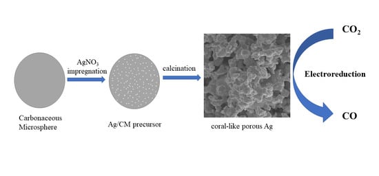
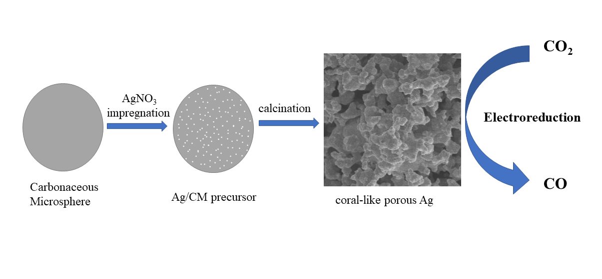
Silver-Carbonaceous Microsphere Precursor-Derived Nano-Coral Ag Catalyst for Electrochemical Carbon Dioxide Reduction

Department of Catalysis Science and Technology and Tianjin Key Laboratory of Applied Catalysis Science & Technology, School of Chemical Engineering and Technology, Tianjin University, Tianjin 300350, China
*
Author to whom correspondence should be addressed.
Catalysts 2022, 12(5), 479; https://doi.org/10.3390/catal12050479
Submission received: 24 March 2022 / Revised: 18 April 2022 / Accepted: 21 April 2022 / Published: 23 April 2022
(This article belongs to the Topic Electromaterials for Environment & Energy)

Abstract

:
The selective and effective conversion of CO2 into available chemicals by electrochemical methods was applied as a promising way to mitigate the environment and energy crisis. Metal silver is regarded as an efficient electrocatalyst that can selectively convert CO2 into CO at room temperature. In this paper, a series of coral-like porous Ag (CD-Ag) catalysts were fabricated by calcining silver-carbonaceous microsphere (Ag/CM) precursors with different Ag content and the formation mechanism of CD-Ag catalysts was proposed involving the Ag precursor reduction and CM oxidation. In the selective electrocatalytic reduction of CO2 to CO, the catalyst 15 CD-Ag showed a stable current density at −6.3 mA/cm2 with a Faraday efficiency (FE) of ca. 90% for CO production over 5 h in −0.95 V vs. RHE. The excellent performance of the 15 CD-Ag catalysts is ascribed to the special surface chemical state and the particular nano-coral porous structure with uniformly distributed Ag particles and pore structure, which can enhance the electrochemical active surface areas (ECSA) and provide more active sites and porosity compared with other CD-Ag catalysts and even Ag foil.

Graphical Abstract

1. Introduction

Electrocatalytic conversion of CO2 into other available chemicals is considered an effective strategy to carry out carbon neutrality [1]. In the past few decades, researchers have found that it is possible to convert CO2 into useful chemicals, such as CO, HCOOH, CH4, C2H6O, C2H4, and so on [2,3,4,5,6], using ambient electrochemical methods. Therefore, electrochemical CO2 reduction reaction (CO2RR) has received wide attention as a promising strategy for carbon cycle and sustainable energy conversion [7]. In order to achieve this goal, an important way is to develop an efficient electrocatalyst with high activity, selectivity, and stability.
In recent decades, researchers have evaluated the selective electrochemical CO2RR over a variety of transition metal materials in CO2-saturated aqueous solutions. Among them, Au [8,9,10,11], Ag [12,13,14,15], and Zn [16,17,18,19] are considered to be effective in the system of electrochemical CO2RR to CO. Although metallic Au usually has the best CO selectivity among these metals, its relatively high cost and low abundance have limited its wide utilization, while the utilization prospect of metallic Zn is also inadequate due to its low CO selectivity [20]. Metallic Ag has drawn extensive attention on account of its moderate cost and high CO selectivity. In order to further enhance the electrocatalytic performance of CO2RR over Ag-based catalysts, various strategies were applied to modify them, including adjusting the size and shape, constructing surface defects, inducing growth of specific crystal planes, and introducing other elements [21,22].
Lu et al. [23] prepared a porous nano-Ag electrocatalyst by dealloying a precursor of Ag–Al alloy and evaluating it in the process of electrochemical CO2RR to CO under moderate overpotentials of <0.50 V. The reason for the high selectivity of ca. 92% over the porous nano-Ag electrocatalyst was attributed to the large ECSA and high intrinsic activity in contrast to polycrystalline Ag. In addition, a series of Ag-based electrocatalysts with excellent performance were also synthesized by treating Ag electrodes via different oxidation-reduction processes. For example, Ma et al. [24] pretreated an Ag electrode by potential anodization in an alkaline solution to obtain a Ag2O layer, and the fabricated Ag2O layer was electrically reduced in situ to an oxide-derived nanostructured Ag (OD-Ag) electrocatalyst at the initial stage of electrolysis. The OD-Ag electrocatalyst showed approximately 80% catalytic selectivity of CO2 electroreduction to CO at 0.49 V. Furthermore, an Ag nano-coral catalyst obtained via oxidation-reduction of chloride precursor [25], and sulfide-derived porous Ag microrods using a facile plasma vulcanization treatment [26], were studied in the CO2 electroreduction process and obtained a magnificent activity for CO production with low overpotential. The nano-Ag electrocatalysts can also be obtained by in situ electrochemical reductions of Ag2CO3, which is formed by anodic-etching of polycrystalline Ag foil and displayed excellent catalytic performance of electrochemical CO2RR to CO [27]. These previous studies illustrate that the Ag-based precursors derived porous nano-Ag electrocatalysts can provide abundant active centers, which is beneficial to achieve excellent electrocatalytic performance.
Herein, we used glucose as the carbon source to form carbonaceous microspheres by hydrothermal synthesis, then prepared several kinds of Ag/CM precursors with different Ag content by the incipient wetness impregnation method, and finally obtained coral-like porous Ag catalyst by calcination. This study provides a new way to prepare silver catalysts with a three-dimensional structure by Ag/C precursor derivatization. Compared with Ag foil, the CD-Ag catalysts can obtain higher current density and FECO at the same potential. Among them, the 15 CD-Ag catalyst has the best catalytic activity and selectivity in the process of electrochemical CO2RR to CO, and it exhibited a stable current density at −6.3 mA/cm2 and a high FE of ca. 90% for CO production over 5 h in −0.95 V vs. RHE. The characterization results indicated that the improved catalytic performance was related to the special surface chemical state, crystal phase composition, and high ECSA which arose from the uniform distribution of Ag particles and porous structure depending on the Ag content in the precursors. Therefore, the nano-Ag-based catalysts prepared by calcining Ag/CM precursors could provide a new design idea for the electrochemical CO2RR to CO.

2. Results and Discussion

2.1. Characterization of the Electrocatalysts

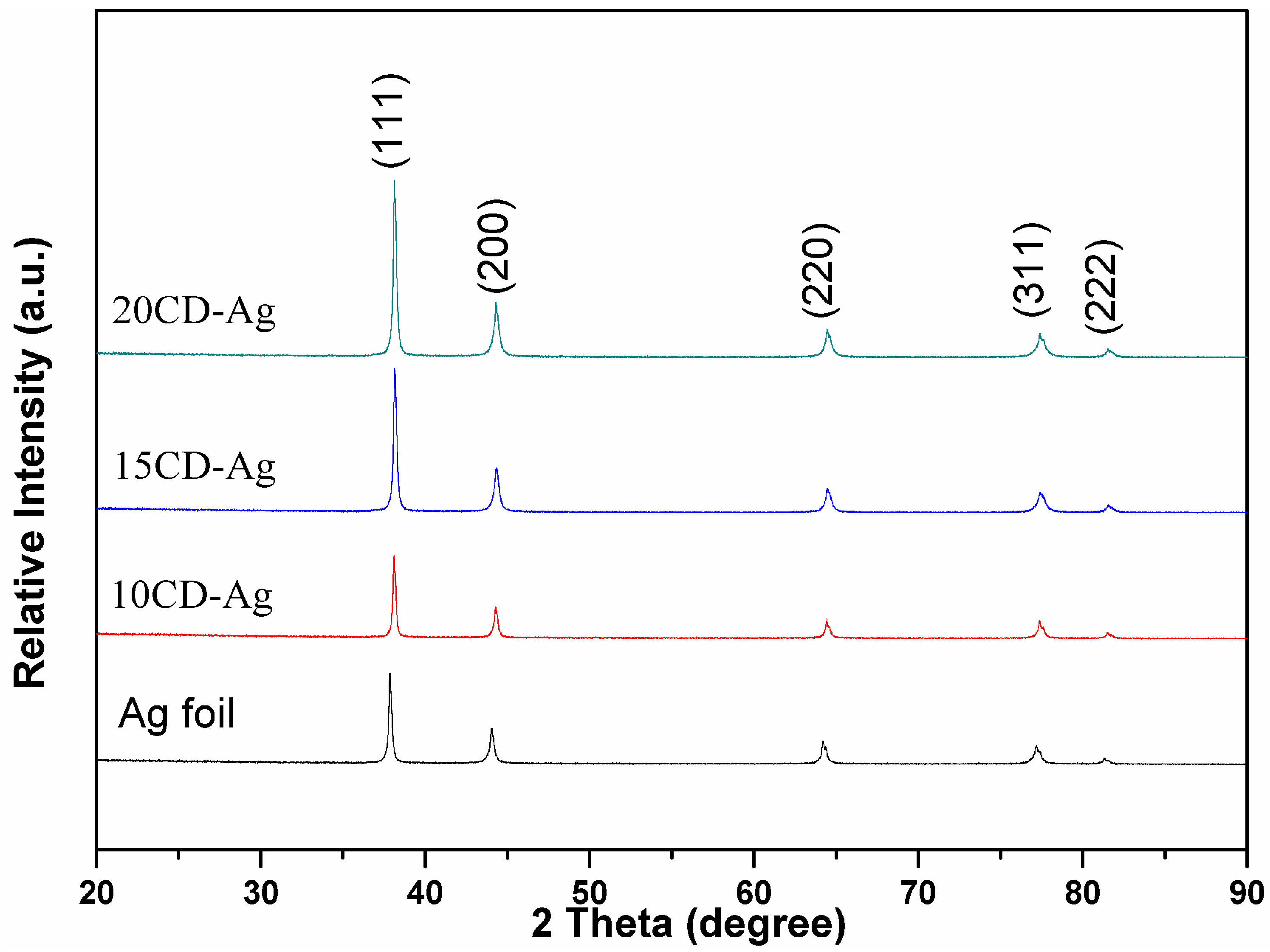
2.1.1. Phase Structure

A variety of physical and chemical characterizations were carried out to explore the properties of catalysts. To analyze the crystal structure of the prepared CD-Ag, the X-ray diffraction (XRD) patterns of three different CD-Ag samples and Ag foil are shown in Figure 1. It shows that the diffraction peaks at angle 2θ equal to 38.1°, 44.3°, 64.4°, 77.4°, and 81.5° correspond to the (111), (200), (220), (311), and (222) crystal planes of Ag [JCPDS file No. 04-0783], respectively, and no other diffraction peaks appear. It can be seen that with the increase in Ag content in the Ag/CM precursor, the relative intensities of the diffraction peak of prepared CD-Ag materials gradually increase. The relatively sharp Ag diffraction peak reflects an enhancement in crystallinity of the Ag phase [28]. This is likely because of the growth of Ag microcrystalline along the (111) and (200) directions with the increasing amount of Ag precursor on CM support during the preparation stage. These results indicated that CD-Ag has a good metallic Ag crystal structure.
As shown in Figure S1, the transmission electron microscopy (TEM) image of all CD-Ag samples was performed. The TEM image of 15 CD-Ag shows the uniformly distributed round Ag nanoparticles with a particle size distribution in the range of 18–78 nm centered at 40 nm, while 10 CD-Ag shows a particle size distribution in the range of 12–82 nm centered at 25 nm, and 20 CD-Ag shows a particle size distribution in the range of 24–86 nm centered at 50 nm. It is worth noting that the particles of the 10 CD-Ag and 20 CD-Ag samples have relatively tight cross-linking, especially the 20 CD-Ag stacking to form irregular bulk. Obviously, with the increase in Ag content in the precursor, the particle size of the as-synthesized CD-Ag catalysts also increases. However, the particles of the 15 CD-Ag samples showed a relatively uniform distribution, while others show different agglomeration and cross-linking states. Furthermore, two clear adjacent lattice spacings of 0.208 nm and 0.234 nm can be found in all high-resolution TEM (HR-TEM) images, which correspond to Ag (200) and Ag (111) crystal planes, respectively. This further confirms the successful preparation of Ag nanoparticles.

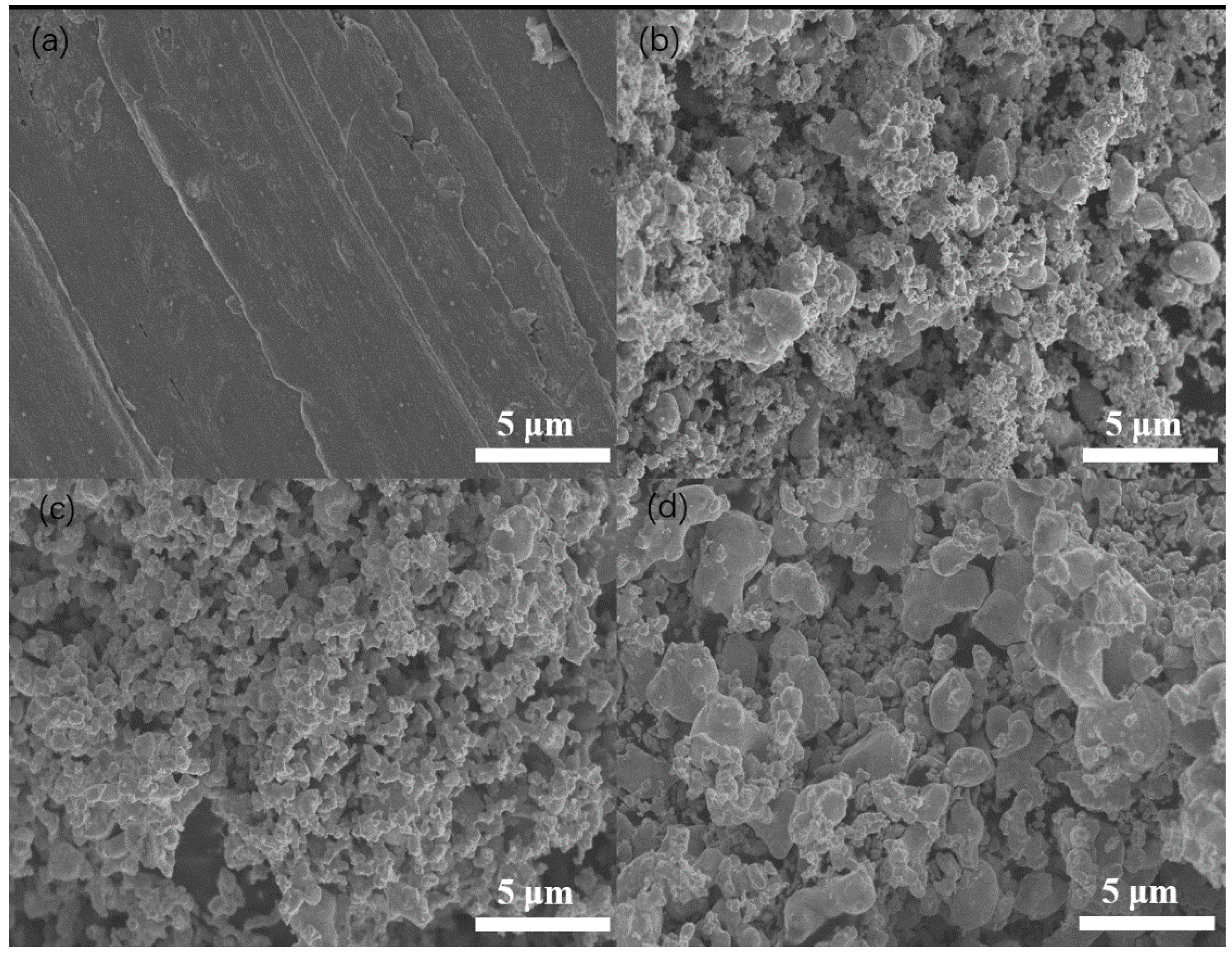
2.1.2. Surface Morphology and Composition

Furthermore, the surface morphology of Ag foil and the prepared CD-Ag materials are characterized by a scanning electron microscope (SEM), and the details are shown in Figure 2. It can be easily recognized that the Ag foil has a relatively flat surface, while the CD-Ag materials demonstrate an obvious three-dimensional coral-like porous structure. Among the three different CD-Ag catalysts, the coral-like porous structure of the 15 CD-Ag is constructed by the uniform and tiny Ag particles together with uniform pore size. On the other hand, a non-uniform Ag particle and pore size distribution can be found for 10 CD-Ag and 20 CD-Ag. Especially, the smaller Ag particles of the 10 CD-Ag are closely combined with each other and some larger Ag particles are dotted among them, while 20 CD-Ag is mainly composed of more large Ag particles along with fewer small Ag particles among them. The burning of carbonaceous microspheres contributes to the formation of abundant pores on the surface of CD-Ag electrode materials [29]. The difference in morphology of three CD-Ag materials should be related to the different loading amounts of Ag on CM, which affects the burning off of CM and the reduction of AgNO3 particles in the calcination process, which then results in different pore structures and Ag particle sizes. The representative SEM image (Figure S2) shows the CM are covered by a uniform shell of AgNO3 particles. The shell thickness is predicted to increase with the increase in Ag content. During the calcination process, the reduction of AgNO3 and oxidation behavior of CM can be described by thermogravimetric analysis (TG), as shown in Figure S3, and the possible reduction reaction is given in Formula (1).
AgNO 3 +   C   =   Ag   +   NO 2 +   CO  
According to the loading amount of Ag and Formula (1), the theoretical mass losses of 10 Ag/CM, 15 Ag/CM, and 20 Ag/CM due to the reduction of AgNO3 by CM are 6.5%, 9.3%, and 12.3%, respectively. Except for 20 Ag/CM, the theoretical mass losses of 10 Ag/CM and 15 Ag/CM are consistent with experimental data at the first step below 250 °C. Therefore, the first mass loss step can be assigned to the reduction of AgNO3 particles by CM, while the second one above 250 °C should be related to the burn-off of CM. For 20 Ag/CM, the difference between the theoretical and experimental values indicates that the AgNO3 particles cannot be fully reduced in the first step arising from the thick AgNO3 shell, weakening the reduction effectiveness of CM. This also means the reduction of residual AgNO3 particles could take place together with the burning-off of CM in the second mass loss step. At high temperatures, many factors, such as the rapid reduction of residual AgNO3 particles, the disappearing confinement of CM, and the heat released from combustion, could result in the metallic Ag particles sintering and their growth in different degrees, along with different pore formations. As for 15 Ag/CM, the AgNO3 particles can be fully reduced at low temperatures. The confinement of pores and surface functional groups of CM is in favor of dispersing and stabilizing the reduced Ag particles. In the second stage, the combustion temperature of CM increases in accordance with the order of 15 Ag/CM, 20 Ag/CM, and 10 Ag/CM, depending on the different activity of Ag species for CM combustion. In any case, the low-temperature combustion of CM can inhibit the growth of Ag particles and damage pore channels easier. These functions result in the formation of small Ag particles and uniform pore size on 15 CD-Ag. The existence of a small amount of big Ag particles and pores on 10 CD-Ag is mainly attributed to the high-temperature removal of CM. For 20 CD-Ag, the formation of a large amount of big Ag particles and pores should be related to the rapid reduction of residual AgNO3 particles along with the high-temperature removal of CM, which accelerates agglomeration, the growth of Ag particles, and the pore collapse of CM. In a word, only the appropriate Ag content in 15 Ag/CM precursors can balance the AgNO3 reduction and carbonaceous microspheres oxidation and obtain the well-dispersed small Ag particles and uniformly distributed pore structure.
Furthermore, we added the SEM images of these CD-Ag catalysts after stability tests in Figure S4 and found that these catalysts exhibited particle agglomeration on the surface after the reaction, especially the 10 CD-Ag electrode had more particle agglomeration than other electrodes. Interestingly, the 20 CD-Ag material is composed of more large particles, but in the SEM images after the reaction, we observed that some large particles peeled off the surface of the 20 CD-Ag electrodes, meanwhile some small particles were exposed.
In addition, the elemental compositions of three CD-Ag samples are analyzed by energy-dispersive X-ray spectroscopy (EDS), and the details are listed in Table S1. It is observed that only elements Ag, C, and O can be detected by EDS and the percentage of the Ag is more than 96.00% and even displays a slight increase trend from 20 CD-Ag to 15 CD-Ag and to 10 CD-Ag. The existence of the O element indicates that the formation of Ag+ is possible on the surface of CD-Ag.

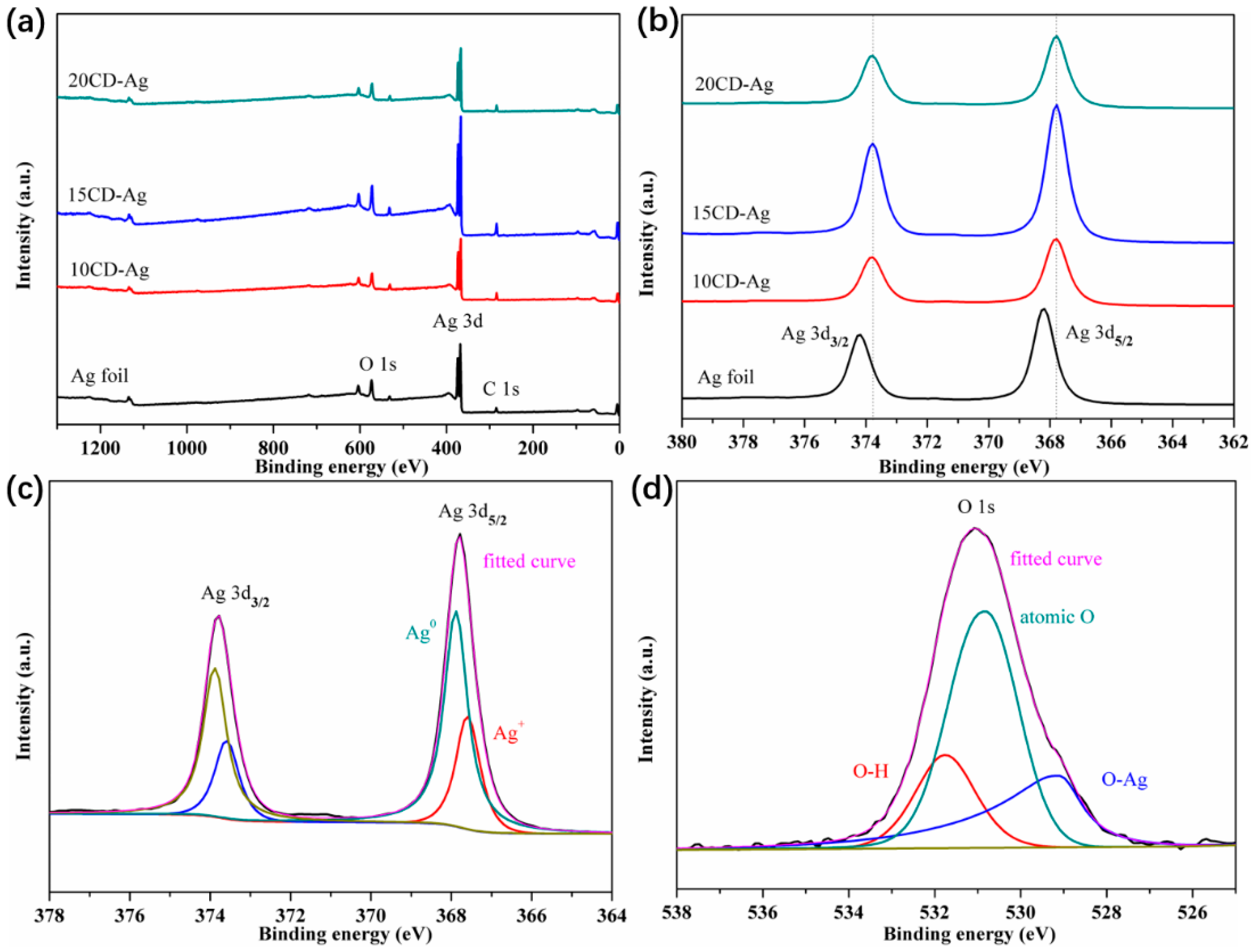
2.1.3. Surface Chemical States of Elements

The surface composition and chemical states of Ag foil and three kinds of CD-Ag materials were investigated by X-ray photoelectron spectroscopy (XPS). As expected by the EDS result, the Ag 3d, C 1s, and O 1s signals appear in the wide scan XPS spectra for all samples (Figure 3a). Figure 3b displays the XPS peak of the Ag 3d region. The bands at the binding energy (BE) of 368.2 eV and 374.2 eV can be attributed to the Ag 3d5/2 and Ag 3d3/2 of the Ag foil, respectively. Compared with the Ag foil, the Ag 3d5/2 and Ag 3d3/2 peaks for the synthesized CD-Ag materials slightly shift to the lower BE value of 367.8 eV and 373.8 eV, respectively. This means the surface electron density of CD-Ag is higher than that of the Ag foil due to the existence of the O species with high electronegativity. The negative shift of BE value also proves that there is a trace amount of Ag+ on the surface of the synthesized CD-Ag materials [30,31]. For the cause of further exploring the chemical state of Ag and O on the surface of the prepared CD-Ag materials, the deconvoluted XPS profiles are shown in Figure 3c,d for 15 CD-Ag and Figure S5 for the others. As for the Ag 3d peak of 15 CD-Ag, two fitting peaks located at the BE values of 367.6 eV and 373.6 eV are ascribed to Ag+, while the other two fitting peaks with BE values of 367.9 eV and 373.9 eV can be attributed to Ag0 [32]. This is because in the air atmosphere of 300 °C, even though the oxidation of CM and the reduction of AgNO3 are dominant, some reduced Ag0 will inevitably be further reoxidized to Ag+ [33]. This discrepancy between XPS and XRD characterization of CD-Ag materials can be attributed to the fact that XPS is a more surface-sensitive technique while XRD is a more bulk-sensitive technique [34]. Moreover, the O 1s spectrum of the 15 CD-Ag material is shown in Figure 3d, which can be deconvoluted into three peaks centered at around 529.1 eV, 530.8 eV, and 531.8 eV, corresponding to the chemically bonded O−Ag specie (OI), the surface absorbed atomic O species (OII) and the residual O−H of H2O (OIII) that possibly existed in the absorbed moisture, respectively [30,35]. As shown in Figure S5, the peak-splitting of Ag 3d and O 1s of the other two CD-Ag materials are similar to the 15 CD-Ag material.

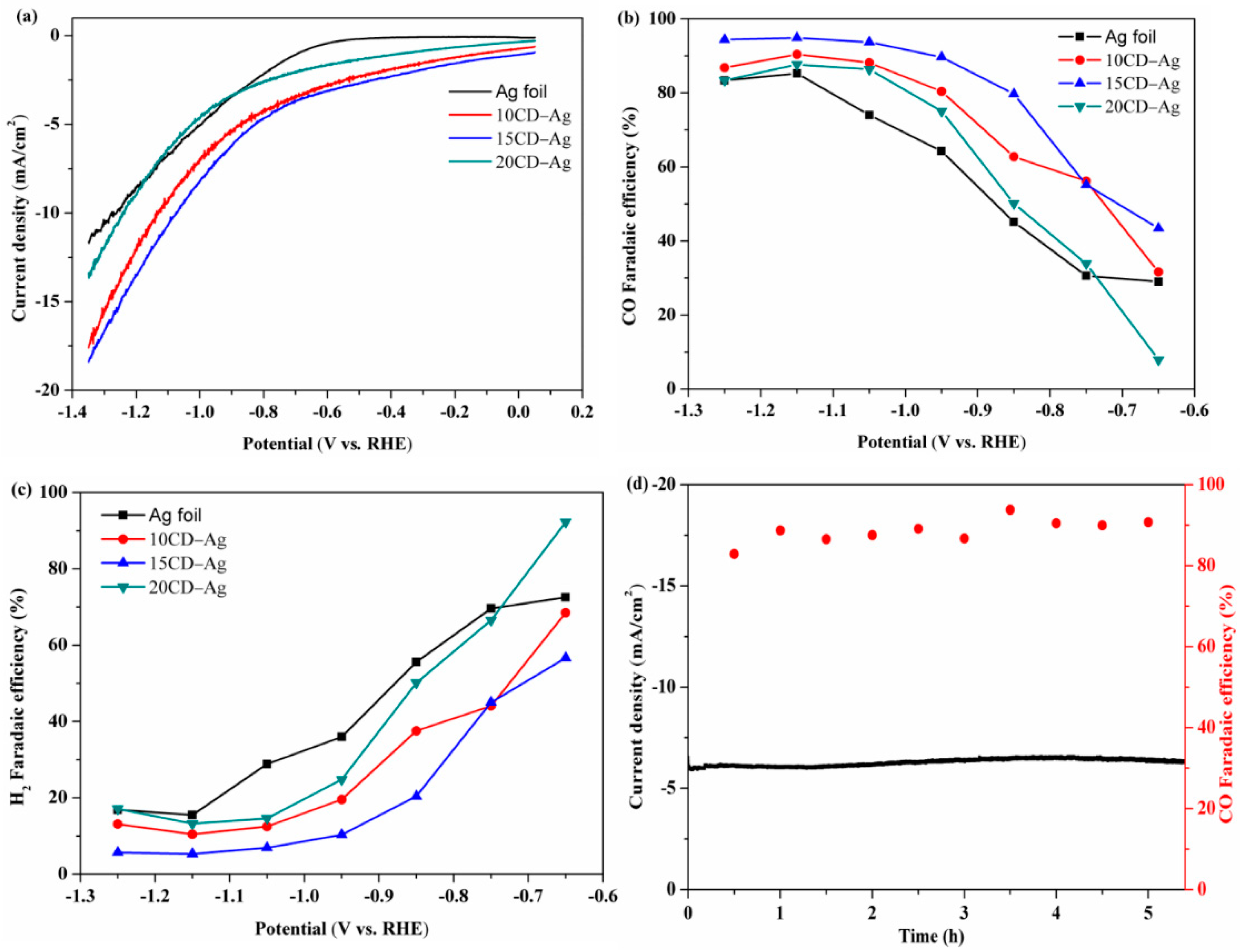
2.2. Electrocatalytic Performance

In order to study the electrocatalytic performance of CO2RR over CD-Ag electrodes with different Ag content in the precursors, the comparison of electrochemical CO2RR activity of Ag foil and CD-Ag electrodes was presented in Figure 4a. By comparing these with the linear sweep voltammetry (LSV) curves for CO2RR over Ag foil and three CD-Ag electrodes it can be observed that the current density displays an increasing trend with the increase in applied potential in the range from −0.35 to −1.35 V vs. RHE for these CD-Ag electrodes, but there is no significant increase for the current density of Ag foil at the low applied potential until the applied potential is higher than −0.65 V vs. RHE, indicating CD-Ag electrodes possess the higher catalytic activity than that of Ag foil. Considering the results of EDS and XPS analysis, the difference in catalytic activity between CD-Ag and Ag foil could be ascribed to the presence of oxygen species on the CD-Ag surface. Related literature by Jee et al. [36] has demonstrated the surface O of Ag electrodes modifies the electronic state of Ag and causes it to have a stronger interaction with *COOH and *CO intermediates, which can decrease the onset potential for CO2RR to CO production. Furthermore, the CD-Ag electrodes have a similar current density growth trend but the current density of the 15 CD-Ag electrode is larger than the other two electrodes at the same applied potential. It can be deduced that the different Ag contents in Ag/CM precursors play an important role in electrochemical CO2RR over these three CD-Ag electrodes.
To better evaluate the enhanced CO2RR performance of CD-Ag electrodes derived from Ag/CM precursors with different Ag content, the controlled potential electrolysis experiments were carried out on Ag foil and CD-Ag electrodes at different applied potentials to plot the FE curves for the main product CO and H2 of CO2RR (Figure 4b,c). As shown in Figure 4b, the FE for CO (FECO) of Ag foil and CD-Ag electrodes gradually increases with enhancing applied potential, all CD-Ag electrodes show higher FECO than Ag foil during a substantial applied potential range, while the 15 CD-Ag electrodes exhibit the best CO2 reduction activity. The FECO of the 15 CD-Ag electrode is close to 90% at −0.95 V vs. RHE and exceeded 90% in the range of −1.05 to −1.25 V vs. RHE. In contrast, the FECO of Ag foil remained below 90% throughout the whole applied potential range. When the FECO of 15 CD-Ag is 89.7% at −0.95 V vs. RHE, the FECO of Ag foil is only 64.3%. Although all CD-Ag electrodes show better electrocatalytic performance than the Ag foil, there are still some differences among them. It can be determined that the 15 CD-Ag electrode has the best selectivity of CO2RR to CO compared to the 10 CD-Ag and 20 CD-Ag, and the 15 CD-Ag electrode can obtain excellent performance of CO2RR to CO in a wide applied potential range. Moreover, the maximum FECO of 15 CD-Ag is 94.9% at −1.15 V vs. RHE, while at the same applied potential, the maximum FECO of 10 CD-Ag and 20 CD-Ag is 90.4% and 87.7%, respectively. Furthermore, as seen in Figure S6, CO partial current density and mass activity of different Ag electrodes at various potentials exhibited a similar trend. The calculated CO partial current density of 15 CD-Ag is higher than those of Ag foil and other CD-Ag in the whole applied potential range. The CO mass activity of 15 CD-Ag is calculated to be 11.7 mA/mg at −0.95 V vs. RHE, while for 10 CD-Ag and 20 CD-Ag catalysts, these values are 7.3 and 7.0 mA/mg, respectively. Indeed, these results further confirm that the 15 CD-Ag sample has the optimal catalytic performance. In the system of electrochemical CO2RR, the H2 evolution reaction (HER) is considered the main side reaction, therefore the increase in the FE for H2 always corresponds to the decrease in FECO (Figure 4c). As expected, the FE for H2 of the four Ag electrodes decreases gradually with the increase in applied potential from −0.65 to −1.15 V vs. RHE and falls from Ag foil to 20 CD-Ag to 10 CD-Ag and to 15 CD-Ag at the same applied potential. These contrasts indicate that CD-Ag electrodes can effectively enhance the electrocatalytic activity and selectivity of CO2RR to CO and significantly inhibit H2 evolution compared with traditional Ag foil material.
The enhancement of the performance should be related to the crystal structure and the special microstructure of CD-Ag electrodes derived from Ag/CM precursors. As indicated by previous studies [13,37], the production efficiency of CO was greatly affected by the crystal structure, and the catalytic activity of electroreduction of CO2 to CO by single-crystal Ag with different crystal faces decreases in the order of Ag (110) > Ag (111) > Ag (100). However, the diffraction peak of Ag (110) was not observed in the XRD pattern because the (110) reflection in a face-centered cubic structure is forbidden. Ham et al. [38] have estimated the relative number of surface (220) by using the intensity ratio of (220) and (111) peaks as a new descriptor, thus reflecting the ratio of (110) structure in Ag catalyst. We compared the (220)/(111) strength ratio by this method and found that from 10 CD-Ag to 15 CD-Ag and to 20 CD-Ag, the (220)/(111) strength ratio of the sample became smaller, suggesting that the highly active Ag (110) structure in CD-Ag decreased as the Ag content in the precursor increased. On the other hand, it is worth noting that in all the HR-TEM images of the CD-Ag catalysts, only the Ag (111) and (200) crystal planes on the catalyst surface can be distinguished, which indicates that the surface of the CD-Ag catalyst is dominated by these two crystal planes, especially Ag (111) planes. These results indicated that in addition to the crystal structure, other factors are also involved in CO production efficiency. Many studies have investigated the role of the surface morphology of catalysts in CO2RR and developed high-performance catalysts by optimizing the surface morphology [39]. The SEM characterization results indicated that Ag materials show different surface morphology (Figure 2). The difference in morphology of three CD-Ag materials should be related to the different loading amounts of Ag on CM, and the details were discussed above. According to the relatively high current density on the 15 CD-Ag electrode, shown in Figure 4, it can be confirmed that the well-dispersed small Ag particles and uniformly distributed pore structure on the 15 CD-Ag electrode provides more active sites to promote CO production than the other electrodes.
Furthermore, it is necessary to evaluate the electrocatalytic stability of the 15 CD-Ag electrode. Therefore, a long-term chronoamperometry experiment of CO2RR was performed on 15 CD-Ag at a moderate applied potential of −0.95 V vs. RHE. As shown in Figure 4d, 15 CD-Ag displays a relatively stable current density of −6.3 mA/cm2 with a FECO of ca. 90% over 5 h. The stability of other electrodes under the same conditions was also tested and the details are shown in Figure S7. The Ag foil also shows a stable current density at −2.2 mA/cm2, but the corresponding FECO presents a severe fluctuation between 40% and 60%. At the same time, the FECO of the 10 CD-Ag quickly decreases from 85% to 60% along with a slight increasing current density from 4.7 to 5.5 mA/cm2 during the reaction time. As for the 20 CD-Ag electrode, shown in Figure S7c, the FECO remains a small fluctuation at about 80% within 5 h, but the current density fluctuates greatly with the reaction time compared to the other electrodes. In order to study the stability of these CD-Ag catalysts, we added the SEM images of these CD-Ag catalysts after stability tests in Figure S3. As shown in Figure S3, excessive particle aggregation on the surface of the 10 CD-Ag electrode reduced the active site of electrochemical CO2RR to CO, which in turn was conducive to the production of H2, thus it was likely the main reason for the decrease in FECO in the 10 CD-Ag electrode. Interestingly, the fresh 20 CD-Ag material has larger Ag particles, so agglomeration is probably not the main reason for its stability change. In fact, a large amount of Ag particles, especially large particles, peeled off from the carbon paper after a reaction of 5 h, as shown in the SEM image of 20 CD-Ag. This phenomenon can explain that the current density of 20 CD-Ag fluctuates in the stability test. Notably, it can be found that the Ag particles on the used 15 CD-Ag electrode are still kept in uniform small corals, which is the same as the fresh one. This indicates that the superior stability of the 15 CD-Ag electrode is mainly related to the stable Ag particle size and porosity. These experimental results show that the 15 CD-Ag electrode demonstrates excellent stability within 5 h.
The comparison of ECSA is another important way to explore the difference in the electrochemical CO2RR performance of Ag foil and CD-Ag electrodes. The ECSA of Ag foil and CD-Ag electrodes were estimated by measuring the double-layer capacitance (Cdl) in 0.1 M KHCO3 electrolyte saturated with CO2. The details are shown in Figure S8, and the Cdl data of these different Ag electrodes are calculated from these results. The linear regression of the Cdl diagram is shown in Figure 5, and the Cdl values corresponding to each sample are summarized in parentheses, which show that the Cdl value of the 15 CD-Ag electrode (5.25 mF/cm2) is more than 40 times larger than that of the Ag foil (0.12 mF/cm2), while the Cdl value of the 10 CD-Ag and 20 CD-Ag electrode correspond to (1.85 mF/cm2) and (1.04 mF/cm2), respectively. Obviously, the 15 CD-Ag electrode exhibits the largest ECSA among these four materials. The increased ECSA represents the exposure of more Ag-active sites [26]. The highest ECSA of the 15 CD-Ag electrode can be attributed to the absence of agglomerates and uniform microstructure, which was proven by SEM. It can be inferred that this is the dominant reason for the excellent electrochemical performance of the 15 CD-Ag electrode.
According to previous literature [13,40,41,42], there are three elementary reaction steps on the Ag electrode for CO2RR to CO:
CO 2 ( g ) + H + ( aq ) + e + *   =   * COOH
* COOH   + H + ( aq ) + e =   * CO + H 2 O
* CO   =   CO ( g ) + *
where * denotes an active site. In the first step of the electrochemical reduction of CO2, the adsorbed *COOH was formed through a proton-coupled electron transfer. Subsequent reactions included the *COOH intermediate gaining a proton and an electron and then reducing *CO and H2O. Finally, the *CO was desorbed from the Ag catalyst surface to form CO. To gain insight into the reaction mechanism for CO2RR to CO, Tafel analysis as an important electrokinetic study to elucidate the CO2 reduction pathway was performed. As shown in Figure S9, the Tafel slope of Ag foil is 150 mV/dec which implies that the rate-determining step (RDS) is described in Equation (3). The Tafel slope on the 15 CD-Ag is 114 mV/dec, which is very close to a theoretical Tafel value of 118 mV/dec, so it can be inferred that the proton-coupled electron transfer step is likely the RDS for the 15 CD-Ag. The 10 CD-Ag and 20 CD-Ag electrodes have a higher Tafel slope of 121 mV/dec and 135 mV/dec, suggesting similar reaction kinetics and rate-limiting steps on all CD-Ag. These results indicated that the CD-Ag might provide more moderate binding energy for the key intermediates of *COOH and *CO than Ag foil, thus decreasing the onset potential and increasing catalytic activity for CO2RR to CO production.
Based on the discussions above, we conclude that the excellent catalytic performance of 15 CD-Ag in the electrochemical reduction of CO2 to CO can be attributed to the following reasons: (1) The characterization results of SEM and TEM proved that the coral-like porous Ag catalyst possesses well-dispersed small Ag particles and uniformly distributed pore structure, which provides a larger ECSA and more accessible active sites to promote CO production, and the catalyst maintains morphological stability after 5 h of electrolysis; (2) The small amount of O on the Ag catalyst surface revealed by the EDS and XPS results could modify the electronic state of Ag and make it have stronger interaction with *COOH and *CO intermediates, which can decrease the onset potential; (3) The XRD results illustrate that the Ag catalyst has a good crystal structure, and the relatively abundant high-activity Ag (110) crystal face exposed on the surface of the catalyst particles enhances the catalytic activity. Moreover, as shown in Table S2, such electrochemical CO2RR catalytic performance of the coral-like porous Ag is comparable to previously reported Ag-based electrocatalysts. These results indicate that the coral-like porous Ag prepared in this study can be used as a highly selective electrocatalyst for electrochemical CO2RR to CO.

3. Materials and Methods

3.1. Materials

Ag foil (purity 99.998%, thickness 0.025 mm) and silver nitrate (AgNO3, 99.995%) were purchased from Alfa Aesar (Shanghai, China). Glucose (C6H12O6) and ethanol (C2H6O) were purchased from Macklin (Shanghai, China). Nafion® perfluorinated resin solution (5 wt% water solution) was purchased from DuPont (Wilmington, DE, USA), carbon paper (CP, TGP-H-60) was purchased from Toray (Tokyo, Japan). Potassium bicarbonate (KHCO3, 99.9%, Aladdin, Shanghai, China) was used to prepare the electrolytes. All solutions were prepared with deionized water.

3.2. Sample Preparation

Carbonaceous microspheres (CM) were synthesized according to the previously reported method [43]. In a typical procedure, 8 g of glucose was dissolved in 70 mL of deionized water to obtain a clear solution, the solution was then transferred and sealed in 80 mL Teflon-sealed autoclave. The Teflon-sealed autoclave was cooled to room temperature under natural conditions after being kept at 180 °C for 4 h. The products were treated by multiple cycles of centrifugation, washing, and re-dispersion in deionized water and further in ethanol until the rinsing solution became neutral and finally dried at 80 °C for 4 h to obtain CM.
The CM-supported Ag samples with different Ag content were obtained by incipient wetness impregnation method. Briefly, the as-synthesized CMs were impregnated with aqueous solution containing AgNO3, and the wet solids were dispersed by ultrasound for 30 min and then placed at room temperature for 12 h, and finally dried at 120 °C for 12 h. The solid products are named 10 Ag/CM, 15 Ag/CM, and 20 Ag/CM, respectively, and the numbers are the mass percentage of Ag calculated by MAg × 100%/(MAg + MCM). The final Ag catalysts were prepared by calcining the precursors at 300 °C for 6 h in air and marked as 10 CD-Ag, 15 CD-Ag, and 20 CD-Ag, respectively. The Ag foil and CP were cleaned by immersion and sonication sequentially in ethanol and deionized water for 30 min.

3.3. Electrode Preparation

Catalyst inks were prepared by mixing deionized water (460 μL), catalyst (10 mg), nafion solution (40 μL), and ethanol (500 μL). The inks were then sonicated for 30 min until obtained a uniform slurry and then painted on the CP with 100 μL ink. After the catalyst ink was loaded on the CP and dried at room temperature, the electrode used in this experiment had a 0.5 mg/cm2 catalyst loading.

3.4. Electrochemical Methods

All electrochemical tests were carried out using an electrochemical workstation (CHI instrument 660E, Chenhua, Shanghai, China) and a three-electrode system was used throughout the process. The counter electrode and reference electrode were gauze platinum electrode and saturated calomel electrode (SCE), respectively. All potentials in this paper are converted to the reversible hydrogen electrode (RHE) reference scale by the following Equation:
E ( vs .   RHE ) =   E ( vs .   SCE ) + 0.0591 × pH + 0.241
Under the experimental conditions, Nafion 117 cation-exchange membrane (Dupont, Wilmington, DE, USA) was devoted to separating the working electrode compartment from the counter electrode compartment in a gas-tight two-component H-type electrochemical cell, and preventing the products produced by the working electrode from diffusing into the counter electrode compartment. An aqueous solution of 0.1 M KHCO3 was used as electrolyte at ambient temperature and pressure, and CO2 was used for purification at a rate of 20 mL/min for at least 30 min prior to measurement. Throughout the test, the electrolyte was stirred at a constant rate using a magnetic stirring device. A gas chromatograph (GC, SP2100) (Shanghai, China) equipped with a TDX-01 column was used to detect the gas-phase products. CO and H2 were quantified by a flame ionization detector (FID, Shanghai, China) equipped with methanizer and thermal conductivity detector (TCD, Shanghai, China), respectively. The FE value of product was calculated by the following Equation:
FE % = z × n × F Q × 100 %                  
where z represents the number of electrons exchanged (z = 2 for CO2RR to CO or H2), n is the mole number of an identified product, F is the Faraday constant (96,485 C/mol), and Q is the total quantity of electric charge passed.

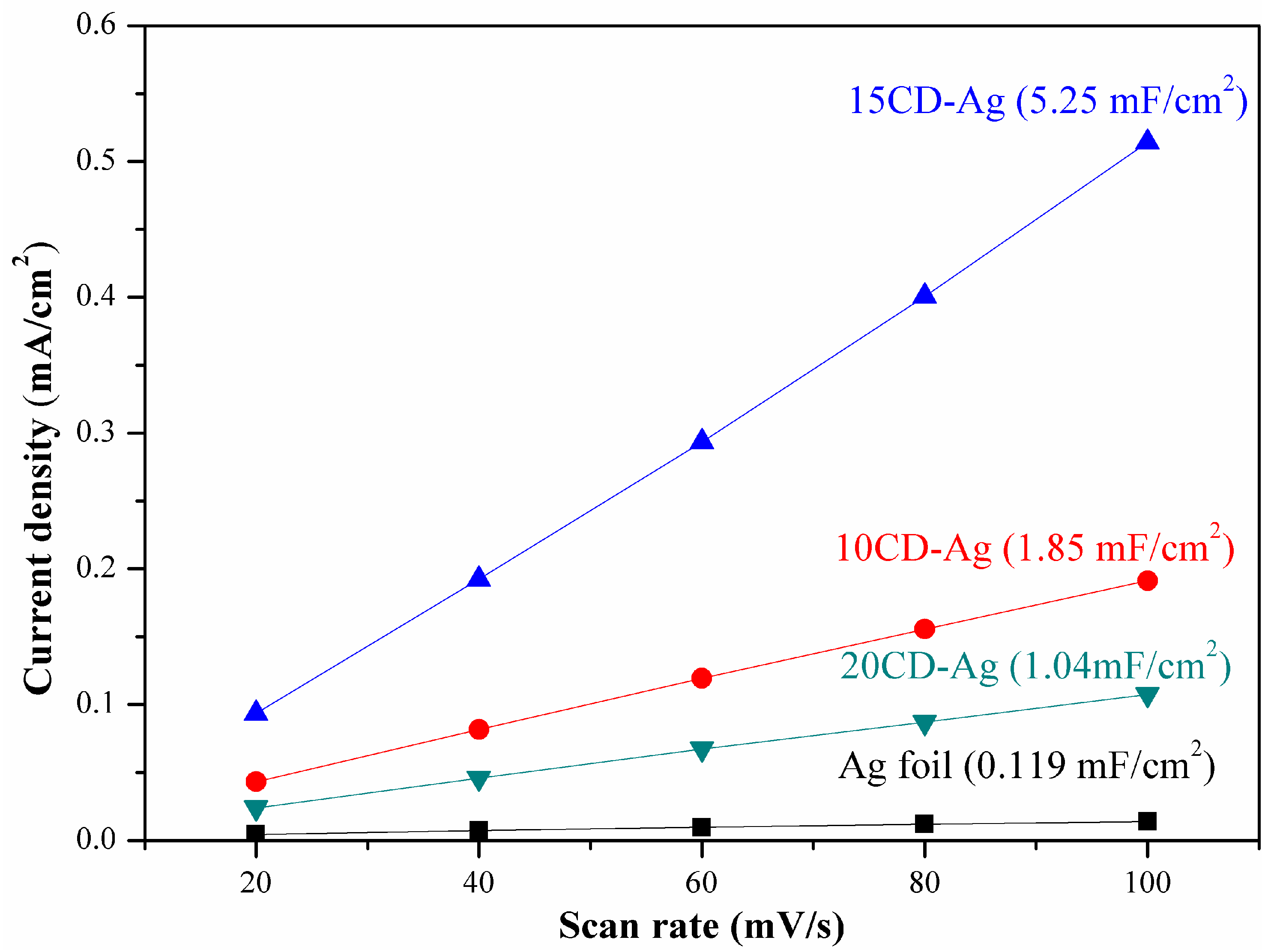
3.5. Electrochemical Active Surface Area

The ECSA was estimated by the Cdl which is measured by the cyclic voltammetry (CV). The CV was tested in the electrolytic cell within the non-Faradaic range (0.65 to 0.45 V vs. RHE) in 0.1 M KHCO3 electrolyte. The Cdl values were calculated by plotting the scan rate versus Δj/2 (where Δj is the difference between cathodic and anodic current densities) at 0.55 V vs. RHE.

3.6. Physical Characterization

XRD tests were performed on a D8-Foucas diffractometer instrument (Bruker AXS GmbH, Karlsruhe, Germany) equipped with Cu-Kα radiation (λ = 0.15418 nm). Scan steps were performed at 8°/min between 2θ values from 10–70°. The SEM (JEOL Regulus 8100, Tokyo, Japan) and TEM (JEOL JEM2100-F, Tokyo, Japan) were used to characterize the morphology and nanostructure of these materials. The EDS coupled to the SEM was carried out with an Oxford Instruments Ultim-max detector (Oxford, England) based on Silicon drift technology with a 100 mm2 active area. The TG (HITACHI STA7300, Tokyo, Japan) with a heating rate of 2 °C/min from room temperature to 300 °C in air was used to analysis the calcination process of the Ag/CM precursors. The surface composition of these materials was investigated by XPS (Thermo Fisher Scientific K-Alpha+, Waltham, MA, USA) with an X-ray source of a monochromatized Al Kα radiation (1486.6 eV). The BE scale was calibrated according to the C 1s peak (284.8 eV).

4. Conclusions

In summary, we prepared CM using glucose as the raw material by the hydrothermal method and obtained a series of Ag/CM precursors with different Ag content by the incipient wetness impregnation method. Subsequently, a series of CD-Ag catalysts were prepared by calcination. Compared to Ag foil, CD-Ag electrodes display better CO2RR performance in a wide potential range, and 15 CD-Ag had the best activity and selectivity. A high FE of 89.7% for CO was achieved on 15 CD-Ag at a potential of −0.95 V vs. RHE, while the FECO of Ag foil was only 64%. The current density and FE of CO for 15 CD-Ag were almost unchanged over 5 h at −0.95 V vs. RHE. Furthermore, the maximum FECO of 15 CD-Ag was 95% at −1.15 V vs. RHE. The significant improvement in catalytic activity and selectivity of CO reduction by CO2 is related to the surface composition and microstructure of the catalyst, among which 15 CD-Ag has the most uniform coral-like porous structure. The uniform pore channel can increase the ECSA, and larger ECSA provides more active sites, thus promoting CO production. The surface O on the catalyst modulated the interaction between Ag and key intermediates *COOH and *CO, thus changing RDS. In addition, the ratio of Ag (110) facets on the catalyst surface also affects the performance of electrochemical CO2RR to CO. This work provides a new catalyst and synthesis method for electrochemical CO2RR, which is a prospective way to solve the challenge of low activity and low selectivity of electrochemical CO2RR.

Supplementary Materials

The following supporting information can be downloaded at: https://www.mdpi.com/article/10.3390/catal12050479/s1, Figure S1: TEM image and the statistics of particle size distribution in inset (a, b, c) and HR-TEM (a’, b’, c’) of different sample 10 CD-Ag, 15 CD-Ag and 20 CD-Ag, respectively; Figure S2: SEM image of the representative sample 15 Ag/CM precursor; Figure S3: Thermogravimetric analysis (TG) profiles for the Ag/CM precursors during the calcination process; Figure S4: SEM images of different CD-Ag electrodes after 5 h electrolysis: (a) 10 CD-Ag; (b) 15 CD-Ag and 20 CD-Ag, respectively; Figure S5: The deconvoluted peak of (a) Ag 3d and (b) O 1s of 10 CD-Ag material and (c) Ag 3d and (d) O 1s of 20 CD-Ag material; Figure S6: CO partial current density depending on applied potential, and (b) mass activity depending on applied potential; Figure S7: Current density and FE of CO during 5 h of long-time operation at −0.95 V vs. RHE for (a) Ag foil; (b) 10 CD-Ag; (c) 20 CD-Ag electrode, respectively; Figure S8: CV curves on (a) Ag foil; (b) 10 CD-Ag; (c) 15 CD-Ag; (d) 20 CD-Ag electrode with a potential range from 0.65 to 0.45 V vs. RHE in a CO2 bubbled 0.1 M KHCO3 electrolyte; Figure S9: Tafel plots of the CO partial current density for Ag foil and CD-Ag. Table S1: The elemental compositions of three CD-Ag samples obtained from EDS; Table S2: Comparison of catalytic performances of our catalyst with different Ag-based electrocatalysts producing CO in the literature. References [44,45] are cited in the supplementary materials.

Author Contributions

Conceptualization, X.L.; methodology, X.L. and S.C.; formal analysis, Y.W.; investigation, X.L.; resources, Y.W.; data curation, S.C.; writing—original draft preparation, X.L.; writing—review and editing, L.Z. All authors have read and agreed to the published version of the manuscript.

Funding

This research was funded by the National Natural Science Foundation of China (21776214).

Data Availability Statement

Data are contained within the article or Supplementary Materials.

Acknowledgments

The authors gratefully thank the State Key Laboratory of Chemical Resource Engineering, Tianjin University, China.

Conflicts of Interest

The authors declare no conflict of interest.

References

  1. Zhang, W.; Hu, Y.; Ma, L.; Zhu, G.; Wang, Y.; Xue, X.; Chen, R.; Yang, S.; Jin, Z. Progress and Perspective of Electrocatalytic CO2 Reduction for Renewable Carbonaceous Fuels and Chemicals. Adv. Sci. 2018, 5, 1700275. [Google Scholar] [CrossRef] [PubMed]
  2. Rosen, B.A.; Salehi-Khojin, A.; Thorson, M.R.; Zhu, W.; Whipple, D.T.; Kenis, P.J.; Masel, R.I. Ionic liquid-mediated selective conversion of CO2 to CO at low overpotentials. Science 2011, 334, 643–644. [Google Scholar] [CrossRef]
  3. Benson, E.E.; Kubiak, C.P.; Sathrum, A.J.; Smieja, J.M. Electrocatalytic and homogeneous approaches to conversion of CO2 to liquid fuels. Chem. Soc. Rev. 2009, 38, 89–99. [Google Scholar] [CrossRef]
  4. Peterson, A.A.; Norskov, J.K. Activity Descriptors for CO2 Electroreduction to Methane on Transition-Metal Catalysts. J. Phys.Chem. Lett. 2012, 3, 251–258. [Google Scholar] [CrossRef]
  5. Kuhl, K.P.; Hatsukade, T.; Cave, E.R.; Abram, D.N.; Kibsgaard, J.; Jaramillo, T.F. Electrocatalytic Conversion of Carbon Dioxide to Methane and Methanol on Transition Metal Surfaces. J. Am. Chem. Soc. 2014, 136, 14107–14113. [Google Scholar] [CrossRef]
  6. Chen, Z.; Wang, T.; Liu, B.; Cheng, D.; Hu, C.; Zhang, G.; Zhu, W.; Wang, H.; Zhao, Z.J.; Gong, J. Grain-Boundary-Rich Copper for Efficient Solar-Driven Electrochemical CO2 Reduction to Ethylene and Ethanol. J. Am. Chem. Soc. 2020, 142, 6878–6883. [Google Scholar] [CrossRef]
  7. Song, R.B.; Zhu, W.; Fu, J.; Chen, Y.; Liu, L.; Zhang, J.R.; Lin, Y.; Zhu, J.J. Electrode Materials Engineering in Electrocatalytic CO2 Reduction: Energy Input and Conversion Efficiency. Adv. Mater. 2019, 32, 1903796. [Google Scholar] [CrossRef] [PubMed]
  8. Ham, Y.S.; Kim, M.J.; Choi, J.; Choe, S.; Lim, T.; Kim, S.-K.; Kim, J.J. Fabrication of Au Catalysts for Electrochemical Reduction of CO2 to Syngas. J. Nanosci. Nanotechnol. 2016, 16, 10846–10852. [Google Scholar] [CrossRef]
  9. Kim, K.-S.; Kim, W.J.; Lim, H.-K.; Lee, E.K.; Kim, H. Tuned Chemical Bonding Ability of Au at Grain Boundaries for Enhanced Electrochemical CO2 Reduction. ACS Catal. 2016, 6, 4443–4448. [Google Scholar] [CrossRef]
  10. Cave, E.R.; Montoya, J.H.; Kuhl, K.P.; Abram, D.N.; Hatsukade, T.; Shi, C.; Hahn, C.; Norskov, J.K.; Jaramillo, T.F. Electrochemical CO2 reduction on Au surfaces: Mechanistic aspects regarding the formation of major and minor products. Phys. Chem. Chem. Phys. 2017, 19, 15856–15863. [Google Scholar] [CrossRef] [PubMed]
  11. Zhu, W.; Michalsky, R.; Metin, O.; Lv, H.; Guo, S.; Wright, C.; Sun, X.; Peterson, A.A.; Sun, S. Monodisperse Au Nanoparticles for Selective Electrocatalytic Reduction of CO2 to CO. J. Am. Chem. Soc. 2017, 139, 9408. [Google Scholar] [CrossRef] [PubMed] [Green Version]
  12. Salehi-Khojin, A.; Jhong, H.-R.M.; Rosen, B.A.; Zhu, W.; Ma, S.; Kenis, P.J.A.; Masel, R.I. Nanoparticle Silver Catalysts That Show Enhanced Activity for Carbon Dioxide Electrolysis. J. Phys. Chem. C 2013, 117, 1627–1632. [Google Scholar] [CrossRef]
  13. Rosen, J.; Hutchings, G.S.; Lu, Q.; Rivera, S.; Zhou, Y.; Vlachos, D.G.; Jiao, F. Mechanistic Insights into the Electrochemical Reduction of CO2 to CO on Nanostructured Ag Surfaces. ACS Catal. 2015, 5, 4293–4299. [Google Scholar] [CrossRef]
  14. Kim, C.; Eom, T.; Jee, M.S.; Jung, H.; Kim, H.; Min, B.K.; Hwang, Y.J. Insight into Electrochemical CO2 Reduction on Surface-Molecule-Mediated Ag Nanoparticles. ACS Catal. 2016, 7, 779–785. [Google Scholar] [CrossRef]
  15. Qi, K.; Zhang, Y.; Li, J.; Charmette, C.; Ramonda, M.; Cui, X.; Wang, Y.; Zhang, Y.; Wu, H.; Wang, W.; et al. Enhancing the CO2-to-CO Conversion from 2D Silver Nanoprisms via Superstructure Assembly. ACS Nano 2021, 15, 7682–7693. [Google Scholar] [CrossRef]
  16. Won, D.H.; Shin, H.; Koh, J.; Chung, J.; Lee, H.S.; Kim, H.; Woo, S.I. Highly Efficient, Selective, and Stable CO2 Electroreduction on a Hexagonal Zn Catalyst. Angew. Chem. Int. Ed. 2016, 55, 9297–9300. [Google Scholar] [CrossRef]
  17. Zhang, T.; Zhong, H.; Qiu, Y.; Li, X.; Zhang, H. Zn electrode with a layer of nanoparticles for selective electroreduction of CO2 to formate in aqueous solutions. J. Mater. Chem. A 2016, 4, 16670–16676. [Google Scholar] [CrossRef]
  18. Nguyen, D.L.T.; Jee, M.S.; Won, D.H.; Jung, H.; Oh, H.-S.; Min, B.K.; Hwang, Y.J. Selective CO2 Reduction on Zinc Electrocatalyst: The Effect of Zinc Oxidation State Induced by Pretreatment Environment. ACS Sustain. Chem. Eng. 2017, 5, 11377–11386. [Google Scholar] [CrossRef]
  19. Guo, M.; Li, X.; Huang, Y.; Li, L.; Li, J.; Lu, Y.; Xu, Y.; Zhang, L. CO2-Induced Fibrous Zn Catalyst Promotes Electrochemical Reduction of CO2 to CO. Catalysts 2021, 11, 477. [Google Scholar] [CrossRef]
  20. Yu, Q.; Meng, X.; Shi, L.; Liu, H.; Ye, J. Superfine Ag nanoparticle decorated Zn nanoplates for the active and selective electrocatalytic reduction of CO2 to CO. Chem. Commun. 2016, 52, 14105–14108. [Google Scholar] [CrossRef] [PubMed]
  21. Sun, D.; Xu, X.; Qin, Y.; Jiang, S.P.; Shao, Z. Rational Design of Ag-Based Catalysts for the Electrochemical CO2 Reduction to CO: A Review. ChemSusChem 2020, 13, 39–58. [Google Scholar] [CrossRef] [PubMed]
  22. Mahyoub, S.A.; Qaraah, F.A.; Chen, C.; Zhang, F.; Yan, S.; Cheng, Z. An overview on the recent developments of Ag-based electrodes in the electrochemical reduction of CO2 to CO. Sustain. Energy Fuels 2020, 4, 50–67. [Google Scholar] [CrossRef]
  23. Lu, Q.; Rosen, J.; Zhou, Y.; Hutchings, G.S.; Kimmel, Y.C.; Chen, J.G.; Jiao, F. A selective and efficient electrocatalyst for carbon dioxide reduction. Nat. Commun. 2014, 5, 3242. [Google Scholar] [CrossRef] [PubMed]
  24. Ma, M.; Trzesniewski, B.J.; Xie, J.; Smith, W.A. Selective and Efficient Reduction of Carbon Dioxide to Carbon Monoxide on Oxide-Derived Nanostructured Silver Electrocatalysts. Angew. Chem. Int. Ed. 2016, 55, 9748–9752. [Google Scholar] [CrossRef] [PubMed]
  25. Hsieh, Y.-C.; Senanayake, S.D.; Zhang, Y.; Xu, W.; Polyansky, D.E. Effect of Chloride Anions on the Synthesis and Enhanced Catalytic Activity of Silver Nanocoral Electrodes for CO2 Electroreduction. ACS Catal. 2015, 5, 5349–5356. [Google Scholar] [CrossRef]
  26. Yang, J.M.; Du, H.S.; Yu, Q.; Zhang, W.; Zhang, Y.; Ge, J.Y.; Li, H.; Liu, J.Y.; Li, H.M.; Xu, H. Porous silver microrods by plasma vulcanization activation for enhanced electrocatalytic carbon dioxide reduction. J. Colloid Interface Sci. 2022, 606, 793–799. [Google Scholar] [CrossRef] [PubMed]
  27. Ma, M.; Liu, K.; Shen, J.; Kas, R.; Smith, W.A. In Situ Fabrication and Reactivation of Highly Selective and Stable Ag Catalysts for Electrochemical CO2 Conversion. ACS Energy Lett. 2018, 3, 1301–1306. [Google Scholar] [CrossRef]
  28. Yu, Y.; Zhong, N.; Fang, J.H.; Tang, S.S.; Ye, X.C.; He, Z.Q.; Song, S. Comparative Study between Pristine Ag and Ag Foam for Electrochemical Synthesis of Syngas with Carbon Dioxide and Water. Catalysts 2019, 9, 57. [Google Scholar] [CrossRef] [Green Version]
  29. Yang, G.; Zhang, J.; Wang, P.; Sun, Q.; Zheng, J.; Zhu, Y. Light scattering enhanced photoanodes for dye-sensitized solar cells prepared by carbon spheres/TiO2 nanoparticle composites. Curr. Appl. Phys. 2011, 11, 376–381. [Google Scholar] [CrossRef]
  30. Zhang, S.; Mo, Z.Z.; Wang, J.; Liu, H.L.; Liu, P.; Hu, D.; Tan, T.X.; Wang, C. Ultra-stable oxygen species in Ag nanoparticles anchored on g-C3N4 for enhanced electrochemical reduction of CO2. Electrochim. Acta 2021, 390, 138831. [Google Scholar] [CrossRef]
  31. Costa, R.S.; Aranha, B.S.R.; Ghosh, A.; Lobo, A.O.; da Silva, E.T.S.G.; Alves, D.C.B.; Viana, B.C. Production of oxalic acid by electrochemical reduction of CO2 using silver-carbon material from babassu coconut mesocarp. J. Phys. Chem. Solids 2020, 147, 109678. [Google Scholar] [CrossRef]
  32. Rocha, T.C.; Oestereich, A.; Demidov, D.V.; Havecker, M.; Zafeiratos, S.; Weinberg, G.; Bukhtiyarov, V.I.; Knop-Gericke, A.; Schlogl, R. The silver-oxygen system in catalysis: New insights by near ambient pressure X-ray photoelectron spectroscopy. Phys. Chem. Chem. Phys. 2012, 14, 4554–4564. [Google Scholar] [CrossRef] [PubMed] [Green Version]
  33. Jiang, K.; Kharel, P.; Peng, Y.; Gangishetty, M.K.; Lin, H.-Y.G.; Stavitski, E.; Attenkofer, K.; Wang, H. Silver Nanoparticles with Surface-Bonded Oxygen for Highly Selective CO2 Reduction. ACS Sustain. Chem. Eng. 2017, 5, 8529–8534. [Google Scholar] [CrossRef]
  34. Jalil, P.A.; Faiz, M.; Tabet, N.; Hamdan, N.M.; Hussain, Z. A study of the stability of tungstophosphoric acid, H3PW12O40, using synchrotron XPS, XANES, hexane cracking, XRD, and IR spectroscopy. J. Catal. 2003, 217, 292–297. [Google Scholar] [CrossRef]
  35. Prieto, P.; Nistor, V.; Nouneh, K.; Oyama, M.; Abd-Lefdil, M.; Díaz, R. XPS study of silver, nickel and bimetallic silver–nickel nanoparticles prepared by seed-mediated growth. Appl. Surf. Sci. 2012, 258, 8807–8813. [Google Scholar] [CrossRef]
  36. Jee, M.S.; Kim, H.; Jeon, H.S.; Chae, K.H.; Cho, J.; Min, B.K.; Hwang, Y.J. Stable surface oxygen on nanostructured silver for efficient CO2 electroreduction. Catal. Today 2017, 288, 48–53. [Google Scholar] [CrossRef]
  37. Hoshi, N.; Kato, M.; Hori, Y. Electrochemical reduction of CO, on single crystal electrodes of silver Ag(111), Ag(100) and Agi(110). J. Electroan. Chem. 1997, 440, 283–286. [Google Scholar] [CrossRef]
  38. Ham, Y.S.; Choe, S.; Kim, M.J.; Lim, T.; Kim, S.-K.; Kim, J.J. Electrodeposited Ag catalysts for the electrochemical reduction of CO2 to CO. Appl. Catal. B Environ. 2017, 208, 35–43. [Google Scholar] [CrossRef]
  39. Pan, F.P.; Yang, Y. Designing CO2 reduction electrode materials by morphology and interface engineering. Energy Environ. Sci. 2020, 13, 2275–2309. [Google Scholar] [CrossRef]
  40. Liu, S.-Q.; Wu, S.-W.; Gao, M.-R.; Li, M.-S.; Fu, X.-Z.; Luo, J.-L. Hollow Porous Ag Spherical Catalysts for Highly Efficient and Selective Electrocatalytic Reduction of CO2 to CO. ACS Sustain. Chem. Eng. 2019, 7, 14443–14450. [Google Scholar] [CrossRef]
  41. He, Z.; Liu, T.; Tang, J.; Zhou, C.; Wen, L.; Chen, J.; Song, S. Highly active, selective and stable electroreduction of carbon dioxide to carbon monoxide on a silver catalyst with truncated hexagonal bipyramidal shape. Electrochim. Acta 2016, 222, 1234–1242. [Google Scholar] [CrossRef]
  42. Qiu, J.P.; Tang, J.T.; Shen, J.; Wu, C.W.; Qian, M.Q.; He, Z.Q.; Chen, J.M.; Song, S. Preparation of a silver electrode with a three-dimensional surface and its performance in the electrochemical reduction of carbon dioxide. Electrochim. Acta 2016, 203, 99–108. [Google Scholar]
  43. Sun, X.M.; Li, Y.D. Colloidal carbon spheres and their core/shell structures with noble-metal nanoparticles. Angew. Chem. Int. Ed. 2004, 43, 597–601. [Google Scholar] [CrossRef] [PubMed]
  44. Xi, W.; Ma, R.; Wang, H.; Gao, Z.; Zhang, W.; Zhao, Y. Ultrathin Ag Nanowires Electrode for Electrochemical Syngas Pro-duction from Carbon Dioxide. ACS Sustain. Chem. Eng. 2018, 6, 7687–7694. [Google Scholar] [CrossRef]
  45. Liu, S.; Tao, H.; Zeng, L.; Liu, Q.; Xu, Z.; Liu, Q.; Luo, J.L. Shape-Dependent Electrocatalytic Reduction of CO2 to CO on Triangular Silver Nanoplates. J. Am. Chem. Soc. 2017, 139, 2160–2163. [Google Scholar] [CrossRef] [PubMed]
Figure 1. XRD patterns of the prepared CD-Ag materials and Ag foil.
Catalysts 12 00479 g001
Figure 2. SEM images of Ag materials: (a) Ag foil; (b) 10 CD-Ag; (c) 15 CD-Ag; (d) 20 CD-Ag.
Catalysts 12 00479 g002
Figure 3. XPS spectra of (a) wide scan region and (b) Ag 3d of Ag foil and three different CD-Ag materials; the deconvoluted peak of (c) Ag 3d and (d) O 1s of 15 CD-Ag material.
Catalysts 12 00479 g003
Figure 4. Electrochemical CO2RR performance of: (a) LSV curves; (b) FE of CO; and (c) FE of H2 over different electrodes at various applied potentials and (d) Current density and FE of CO vs. reaction time over 15 CD-Ag electrode during 5 h of long-time operation at −0.95 V vs. RHE.
Catalysts 12 00479 g004
Figure 5. The linear regression of the Cdl of Ag foil and three different CD-Ag electrodes and the Cdl values listed in parentheses.
Catalysts 12 00479 g005
Publisher’s Note: MDPI stays neutral with regard to jurisdictional claims in published maps and institutional affiliations.

