Article

The Conversion of Waste Biomass into Carbon-Supported Iron Catalyst for Syngas to Clean Liquid Fuel Production

1
U.S.-Pakistan Centre for Advanced Studies in Energy (USPCAS-E), Department of Energy Systems Engineering, National University of Sciences and Technology, Islamabad 44000, Pakistan
2
Department of Energy Systems Engineering, Seoul National University, Seoul 08826, Korea
3
DEQ, ETSEQ, Universitat Rovira i Virgili, Avinguda dels Països Catalans 26, 43007 Tarragona, Spain
4
Department of Chemistry, College of Science, King Saud University, Riyadh 11451, Saudi Arabia
5
Department of Materials Technologies, Faculty of Materials Engineering, Silesian University of Technology, 44-100 Gliwice, Poland
6
CEMMPRE-Center for Mechanical Engineering Materials and Processes, Department of Mechanical Engineering, University of Coimbra, Rua Lui’s Reis Santos, 3004-531 Coimbra, Portugal
*
Authors to whom correspondence should be addressed.
Catalysts 2022, 12(10), 1234; https://doi.org/10.3390/catal12101234
Submission received: 26 August 2022 / Revised: 7 October 2022 / Accepted: 8 October 2022 / Published: 14 October 2022
(This article belongs to the Special Issue New Trends in Catalysis for Sustainable CO2 Conversion)

Abstract

:
Syngas has been utilized in the production of chemicals and fuels, as well as in the creation of electricity. Feedstock impurities, such as nitrogen, sulfur, chlorine, and ash, in syngas have a negative impact on downstream processes. Fischer–Tropsch synthesis is a process that relies heavily on temperature to increase the production of liquid fuels (FTS). In this study, waste biomass converted into activated carbon and then a carbon-supported iron-based catalyst was prepared. The catalyst at 200 °C and 350 °C was used to investigate the influence of temperature on the subsequent application of syngas to liquid fuels. Potassium (K) was used as a structural promoter in the Fe-C catalyst to boost catalyst activity and structural stability (Fe-C-K). Low temperatures (200 °C) cause 60% and 80% of diesel generation, respectively, without and with potassium promoter. At high temperatures (350 °C), the amount of gasoline produced is 36% without potassium promoter, and 72% with promoter. Iron carbon-supported catalysts with potassium promoter increase gasoline conversion from 36.4% (Fe-C) to 72.5% (Fe-C-K), and diesel conversion from 60.8% (Fe-C) to 80.0% (Fe-C-K). As seen by SEM pictures, iron particles with potassium promoter were found to be equally distributed on the surface of activated carbon.

1. Introduction

Researchers throughout the world are striving to develop alternate technologies for manufacturing chemicals and hydrocarbons from coal as crude oil sources becomedepleted [1,2]. Fischer–Tropsch Synthesis was invented by a German chemist (FTS). Syngas, a mixture of hydrogen and carbon monoxide produced from coal, natural gas, or biomass, is used in the FTS process [3]. There are two stages to the FT reaction. The catalyst is employed in the first stage to produce straight-chain hydrocarbons, as well as water and/or carbon dioxide [4]. Hydrocracking is employed in the second stage to create the products and split them into liquid fuel. To boost production, various catalysts (Fe, Co, Ru, and Ni) have been utilized [3]. Due to their better conversion and selectivity, as well as their ease of CO dissociation, metal catalysts are favored in the FTS process [5]. Due to their inexpensive cost, favorable reactional conditions, and high catalytic activity, iron (Fe) and cobalt catalysts are frequently selected and utilized in commercial FTS reactors [6].
Fe catalysts are less expensive than other catalysts, and provide more product distribution flexibility than other catalysts. The Fe-based catalyst is more appealing, since it has a better water gas shift reaction with a lower H2/CO ratio [3]. For iron-based catalysts, there are two forms: supported and bulk, both of which are manufactured using the wet impregnation method. To prevent particle agglomeration, a supported iron catalyst requires the inclusion of metal support. In comparison to bulk iron catalysts, they can also have a higher mechanical strength [7]. Some support materials, such as SiO2, Al2O3, TiO2, and carbon, have been widely used in recent research to influence catalyst performance in the FTS process [8,9]. The FTS activity and selectivity are influenced by the physical and chemical features of the support. They have been used for a long time to help with the FTS process. Carbon compounds, such as carbon black and activated carbon, have been used for this purpose [10]. Supported iron FT catalysts provide a larger iron dispersion; therefore, research has shifted away from bulk iron FT catalysts in recent years. Supported iron catalysts improve the performance of iron species by optimizing the interaction of iron species with support catalysts [11].
An iron metal catalyst’s support serves as a macromolecular ligand that either directly or indirectly increases the reactivity of the active site [7]. Carbon materials’ catalytic performance is influenced by their electrical characteristics, surface chemistry, and porous structure [12]. Because activated carbons have a porous morphology, they havebeen used as a support material. In this study, activated carbon derived from “Lantana Camara” is used as a support. Selecting the right carbon support could affect the overall FTS process [13,14].
Lower activity is one of the key problems of iron-based catalysts, which can be improved by using the correct promoters, such as potassium, sodium, and copper, which are regarded as advantageous for Fe-catalysts. To improve selectivity and optimize the spatial organization of active iron species, a variety of promotors are utilized [3]. Researchers have recently focused their attention on promoters such as potassium, copper, sodium, and manganese [6]. Potassium (K) promoter has been widely used in carbon-supported iron catalysts to improve the selectivity of hydrocarbons. Potassium promoter reduces methane formation, and enhances the production of short olefins. The use of potassium promoter with carbon support showed a marginal effect on the reactivates of CO and CO2. The addition of potassium as a promoter creates effects on an optimized iron-carbide by donating electrons to an active surface of iron. That is why potassium is used as a promoter in this study. For this purpose, the incipient wetness impregnation method was used to produce the carbon-supported iron catalyst with potassium promoter for Fischer–Tropsch synthesis [14].
FTS reactions are classified into two types: low-temperature FTS reactions (200–280 °C) and high-temperature FTS reactions (300–350 °C). The low temperature FTS reactions have been used to make specific C5+ hydrocarbons. For the coproduction of liquid hydrocarbons, however, high temperature FTS reactions have been used. At a temperature of 270 °C, the synergistic effect of active co-sites and acidic sites has been deemed the best reaction temperature for gasoline synthesis [15]. Given the foregoing, the goal of this research was to look at FTS reactions at low temperatures (LT-FTS) of 200 °C and high temperatures (HT-FTS) of 350 °C to see how reaction temperature and catalyst type affected direct syngas conversion via Fischer–Tropsch synthesis. Potassium (K) was used as a “structural promoter” (Fe-C-K) to make the Fe-C catalyst more active and stable, and its effect on the next process will be looked into as well.
To the best of our knowledge, no study on the development of a carbon-supported iron catalyst by using Lantana Camara has been conducted. The oil nature of Lantana Camara enhanced the production of gasoline and diesel. Therefore, this article could be beneficial for researchers and industrialists for the preparation of a carbon-supported catalyst by using Lantana Camara as a carbon support.

2. Results and Discussions

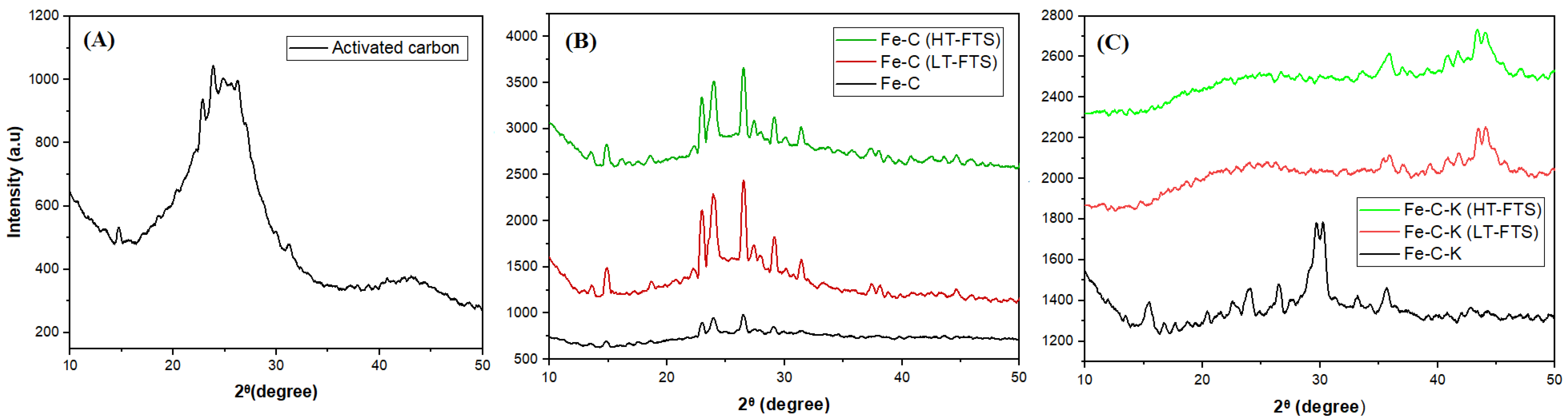
2.1. X-ray Diffraction

Figure 1 depicts changes in the crystal structure of various catalysts (Figure 1A–C). A carbonaceous structure peak at angle 23 can be observed in the XRD pattern of activated carbon derived from “Lantana Camara” in Figure 1A [16]. Three processes are involved in the chemical activation using H3PO4: dehydration, degradation, and coagulation. Research revealed that the phosphoric acid forms pores with raw precursor during the carbonization phase [17,18].
Figure 1B shows the XRD patterns of the carbon-supported iron catalyst, Fe-C. Because activated carbon was utilized as a support, the large peak at 23° can be attributed to the amorphous structure of the carbon. The reflection at a value of 26.5° becomes more discernible during FTS reactions, and is attributed to the graphite carbon [19]. The peak at angles of 24° and 32° in both low- and high-temperature catalysts (Fe-C (LT-FTS) and Fe-C (HT-FTS)) demonstrates the creation of Fe2O3 [7].
Figure 1C shows the XRD patterns of the carbon-supported iron catalyst with potassium promoter (Fe-C-K). Iron carbide (Fe3C) synthesis in the Fe-C-K catalyst at an angle of 37° at low and high temperatures is responsible for the formation of gasoline [20]. During the activation procedure, Fe2O3 were converted to Fe3O4and Fe5C2 [21]. Researchers suggested that the creation of Fe5C2 at all times boosts diesel formation [22,23]. The Fe5C2 is considered as an active phase, and is critical for obtaining simultaneous improved selectivity and activity in iron-based Fisher–Tropsch synthesis. Thermal reduction and carburization methods have been frequently used for this purpose. The creation of Fe5C2 occurs during the FTS reaction, as shown by the post Fe-C catalyst, and this is observed at an angle of 44° [24]. It was thought that iron carbide (Fe3C) to Fe5C2, which has a better ability to pick out C5+, was the most active iron phase for making the FTs [25]. The results show that changing the catalyst qualities by changing the chemical and physical properties of carbon improves metal oxide reduction [7].

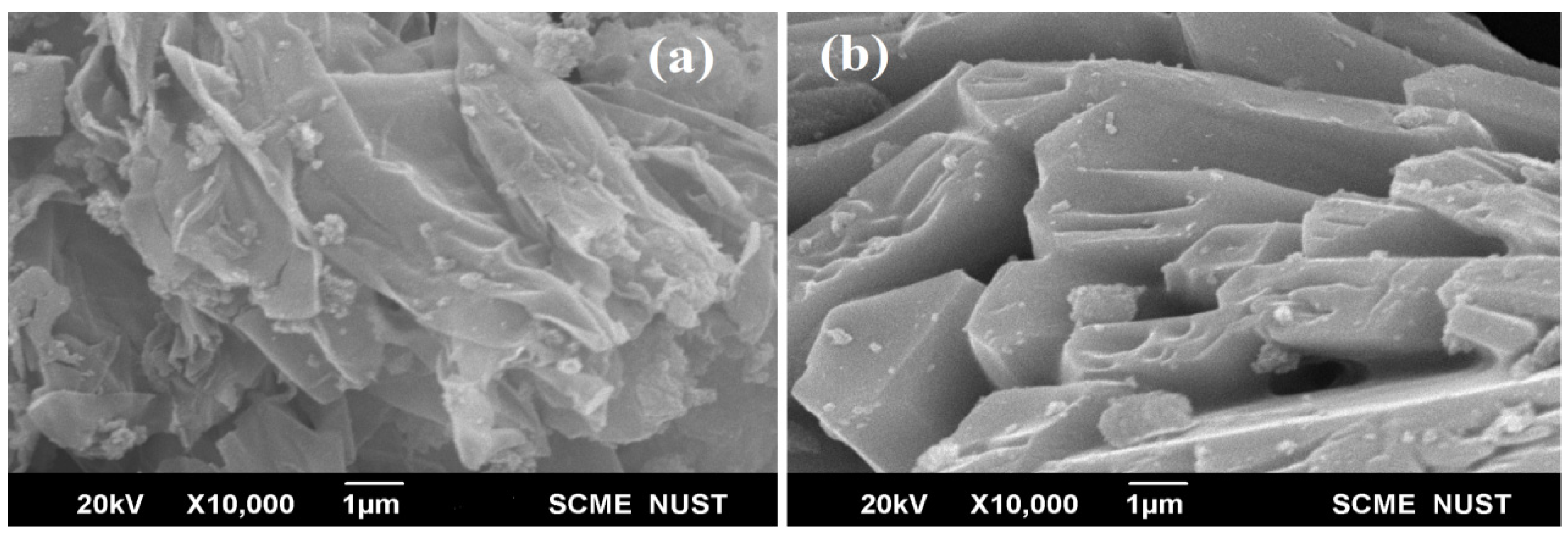
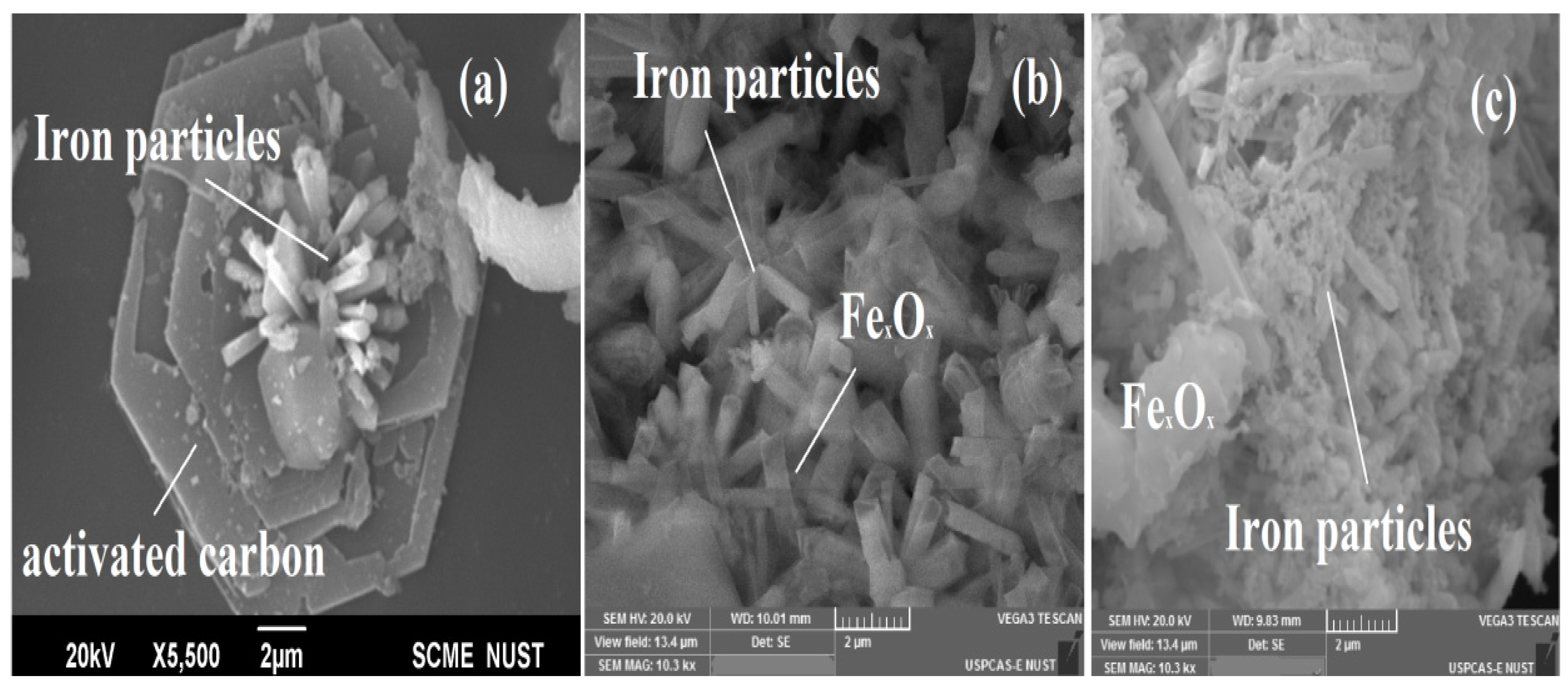
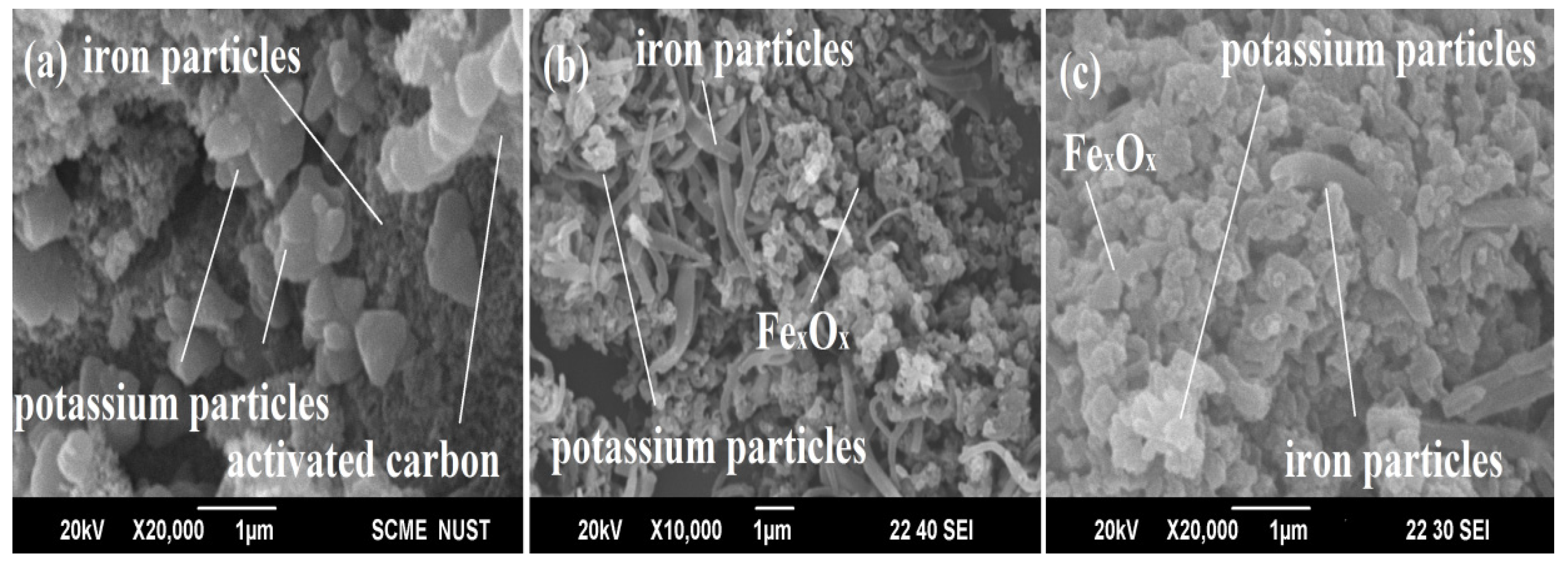
2.2. Scanning Electron Microscopy

Scanning electron microscopy (SEM) images of activated carbon are shown in Figure 2a,b, demonstrating that its interior surface is riddled with voids. These chambers are upright to allow for the development and provision of iron particles, resulting in long-lasting contact between carbon and iron particles.
Figure 3a shows the precise development of iron particles on the surface of activated carbon. On the surface of activated carbon, the production of needle formations is uniformly distributed. The Fe-C (Figure 3b) iron particles are absorbed and agglomerated during the low-temperature (LT-FTS) reaction due to an increase in the Fe crystallite size. The Fe-C (Figure 3c) marginally alters the activation of iron oxides in a high-temperature (HT-FTS) reaction. This demonstrates that temperature has a significant impact on the structure and properties of the catalyst.
In Figure 4a, the potassium particles are dispersed into the carbon surface to create the circular structure. This is because only 3% of the promoter was used. The needle and spherical Fe-C-K particles (Figure 4b) react inside the FT reactor to generate carbide particles when a low-temperature (LT-HTS) reaction is carried out. Figure 4c shows that Fe-C-K particles bonded each other to form active carbide phase at high temperatures (HT-FTS).

2.3. Energy-Dispersive X-ray Analysis

The EDS results of the catalyst show that the increase in the carbon percentage in the catalysts are responsible for the development of the active carbide phase. Additionally, the presence of oxygen is responsible for the development of Fe2O3 and Fe3O4[26]. Table 1 shows the EDS analysis of the prepared catalysts.

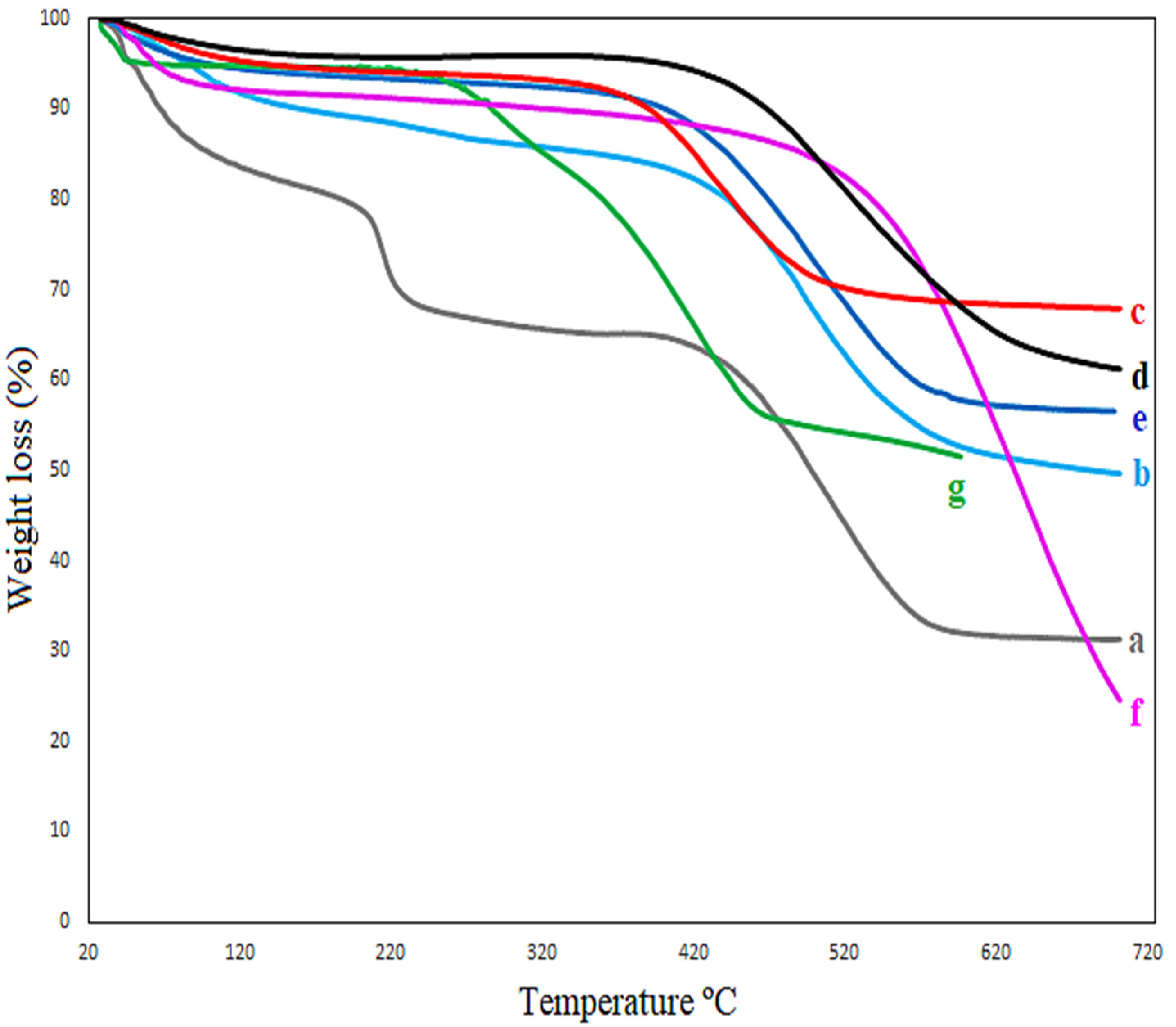
2.4. Thermogravimetric Analysis

Figure 5 shows the thermal stability of activated carbon (a), as well as the catalysts, Fe-C (b) and Fe-C-K (e). At a temperature of 110–250 °C, the water molecules are evaporated [17]. In Figure 5, the evaporation of water molecules occurred between 110–250 °C, as shown by Equations (1)–(4). At roughly 450 °C, partial thermal degradation of the carbon-supported iron-based catalyst with and without potassium promoters occurs at low and high temperatures, as illustrated in Figure 5b–d,f,g, and shown by Equations (5) and (6). Above 550 °C, however, full thermal damage occurs, as shown by Equations (7)–(10). The following steps describe the overall process of thermal degradation of the Fe-C catalyst with and without potassium promoter (Equations (1)–(10)). First, goethite decomposes (Equation (1)) between 200 and 250 degrees Celsius [27,28]. The shape of Fe2O3 (hematite) is then reduced to FeO. In addition, the reaction of iron oxide with CO at 250–300 °C produces Fe2O3(magnetite) (Equations (2)–(6)). In the XRD peaks, the production of magnetite was also plainly visible. The creation of CO2 is linked to the reduction of iron oxides to generate the iron carbide carbonaceous material at temperatures above 350 °C, as shown by Equations (7)–(10) [29].
2 FeO ( OH ) Fe 3 O 3 + H 2 O
3 FeCO 3 Fe 3 O 4 + 2 CO 2 + CO
FeCO 3 FeO + CO 2
FeC 2 O 4 · 2 H 2 O FeC 2 O 4 + 2 H 2 O
3 FeC 2 O 4 Fe 3 O 4 + 4 CO + 2 CO 2
3 Fe 2 O 3 + CO 2 Fe 3 O 4 + CO 2
6 FeO ( OH ) + CO 2 Fe 3 O 4 + CO 2 + 3 H 2 O
FeC 0 3 FeO + CO 2
xFe 3 O 4 + xCO 3 Fe x C + xCO 2
xFeO + xCO Fe x C + xCO 2

2.5. Brunauer–Emmett–Teller Analysis

The BET surface area of activated carbon and the produced catalyst is shown in Table 2. The results reveal that the surface area of activated carbon is 167.4 m2/g, and the surface area of the Fe-C catalyst is 78.7 m2/g. The surface area of the potassium-based promoter catalyst was reduced by 11.1 m2/g because its particles occluded tiny holes of the active sites with their own particles. The high surface area of activated carbon, as compared to the iron catalyst in the iron phase, is greatly disseminated over the surface, forming minute particles of iron oxides. When Fe2O3 is calcined, it can transform into Fe3O4. Surface carbon species may be able to aid this process by acting as an active support [30].

2.6. Effect of Temperature and Promoter on Downstream Syngas Applications

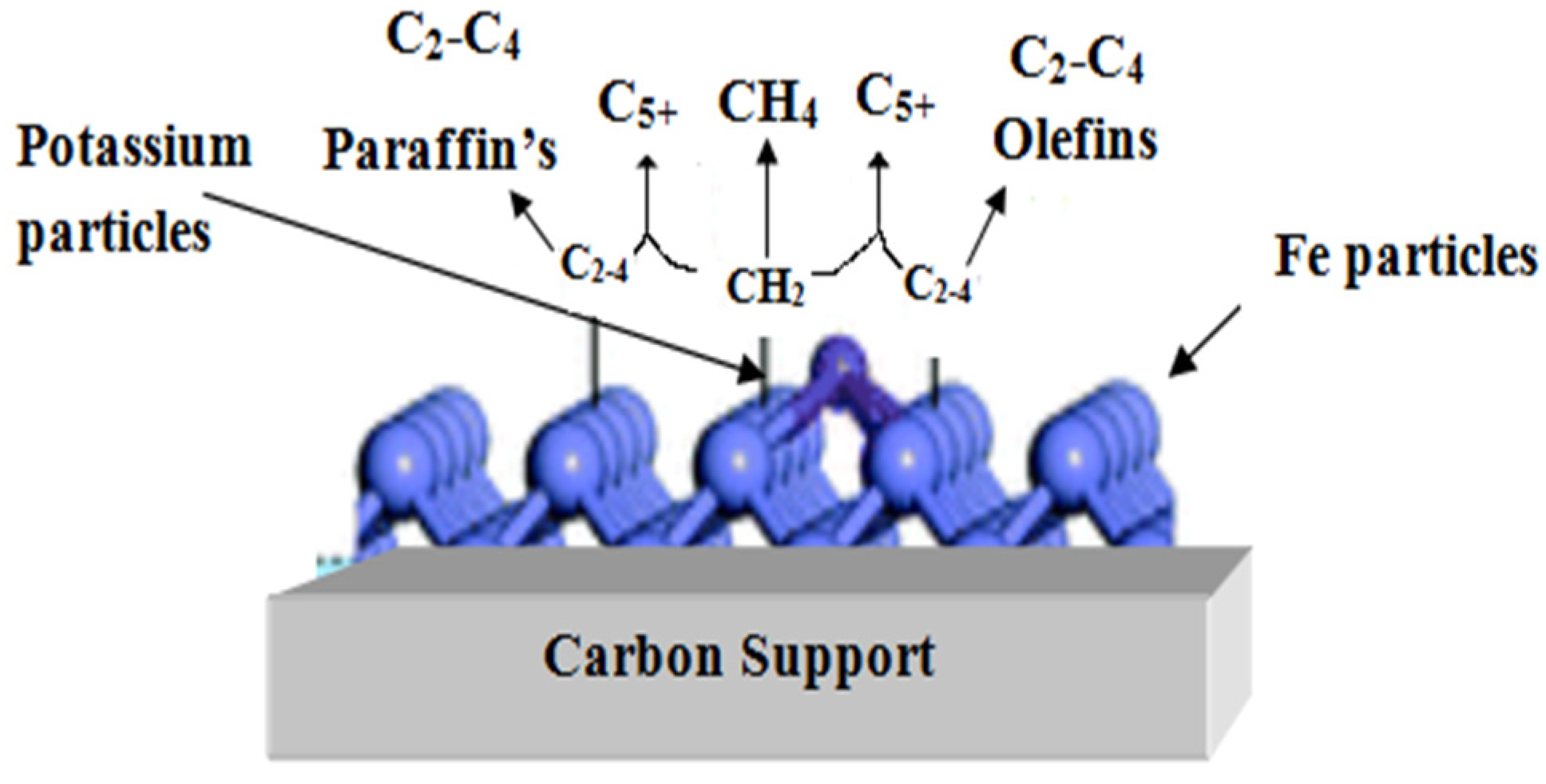
2.6.1. Effect of Promoter and Carbon Support

Table 3 shows that adding potassium promoter in an iron carbon-supported catalyst has a substantial impact on the conversion of gasoline, from 36.4 percent (Fe-C) to 72.5 percent (Fe-C-K). A low potassium concentration is thought to be beneficial for promoting the FTS reaction and converting iron carbides to the inactive iron oxide phase. Potassium offers a number of benefits, including increasing the quantity of alkenes in hydrocarbon synthesis, and inhibiting the creation of methane [31]. In general, using a potassium promoter in conjunction with an Fe/Ac-based catalyst reduces the quantity of n-paraffins in FTS products while significantly increasing branching paraffin [32]. When promoters are added to an iron-based catalyst, the catalyst’s physical and chemical properties change, as well as the conversion and selectivity of CO2 and C5+ [33]. The support of carbon helps for the formation of the iron-carbide phase. Due to the iron-carbide phase, the conversion rate of gasoline and diesel was increased. The Figure 6 shows the mechanism of a carbon-supported iron catalyst containing potassium as a promoter.
Potassium was found to be a good promoter that enhanced the water–gas shift reaction, enhancing the selectivity toward olefins, and suppressing the formation of methane. Potassium promoter improves the performance of an iron catalyst by affecting the catalyst phase. In a catalyst, potassium acts as an electron donor when absorbed on the surface of an iron carbide-oxide phase. It inhibits the reduction from α-Fe2O3 to α-Fe3O4, and promotes CO dissociation. In general, a small amount of potassium as a promoter is sufficient to stimulate FTS activity [31,32,33,34]. In this study, the results revealed that the use of potassium as a promoter suppressed the formation of methane, and enhanced the C5+ formation.

2.6.2. Effect of Temperature

The active phase of iron-based catalysts is affected by the operating temperature of FTS. The iron oxide FeO becomes hematite Fe2O3, and then magnetite Fe3O4 when the temperature of the reactor rises [35].The iron particles of the promoted catalyst stabilize on the surface of the carbon matrix during the FTS reaction, preventing aggregation [36]. When using a carbon-supported iron catalyst without a promoter at higher temperatures, the number of non-oxygenates increased from 53% to 66%. (Fe-C). In a carbon-supported iron catalyst system with the promoter, the number of non-oxygenates increased from 81.7 percent to 82.8 percent at a higher temperature (Fe-C-K). Diesel generation increased from 60% to 80% at low temperatures (200 °C), with and without the potassium promoter. In the absence of a potassium promoter, however, the synthesis of gasoline increased from 36% to 72% at high temperatures (350 °C). The results of carbon chain distribution with and without oxygenates are shown in Table 3.

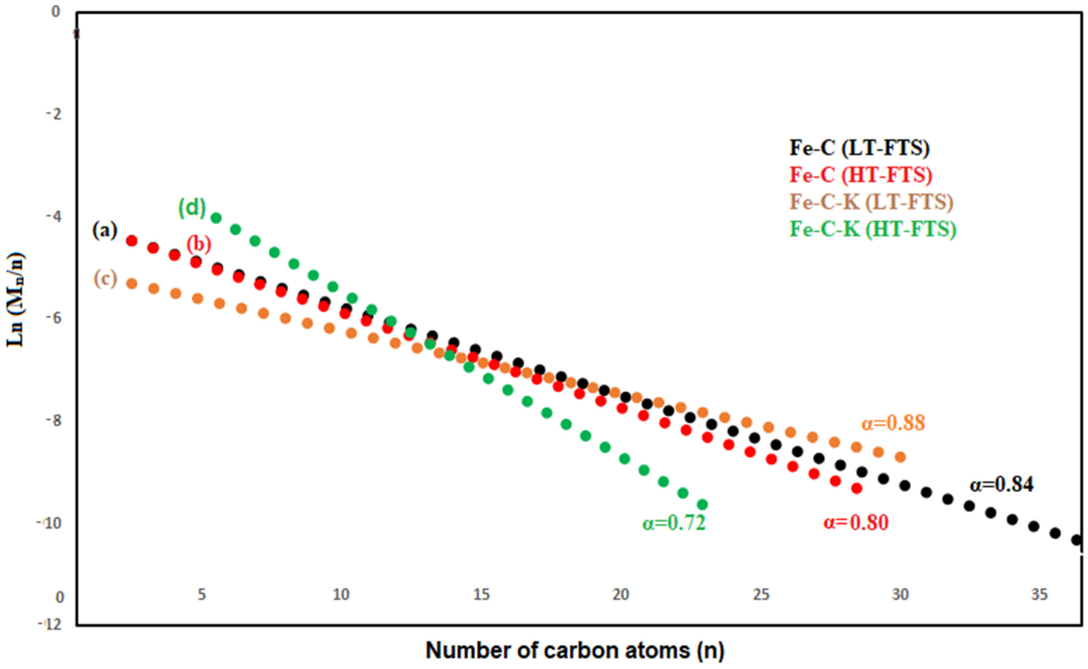
2.6.3. Carbon Chain Distribution

The FTS method may create C5–C11(gasoline) and C12–C22(diesel) hydrocarbon chains, making it a desirable transportation fuel. Various characteristics, such as the active phase and the quality of the support utilized, were used to evaluate the performance of FTS catalysts [37]. The FTS test was carried out with and without potassium promoters on a carbon-supported iron catalyst. After a reduction reaction at 450 degrees Celsius, water molecules were formed as a result of pre-adsorbed water molecules on the catalyst surface. When hydrogen and oxygen that have been adhered to the catalyst mix and begin to break down, they can produce water.
As a result, there were two main sources of adsorbed oxygen: first, polluted molecular oxygen from the gas phase, and second, the CO dissociation product. Fe5C2 was formed during the reduction reaction, which is considered the most active phase of the process [38,39]. Furthermore, the use of activated carbon increased the catalytically active phase’s anchoring. The samples from the separators were collected in glass vials and sealed to prevent evaporation after the reaction. The lower white layer in Figure 7, which is oxygenated, and the higher brown layer, which contains C5+ hydrocarbons, were separated in the collected samples. Figure 8 depicts the results, which show various peaks and all potential chemicals included in the product. The overall percentage of different hydrocarbons in the mixture is shown in Table 3.

2.6.4. P’s Influence

Because phosphorus causes choking during the reaction in a fixed bed reactor, and affects reactor performance, it is not considered as good for the FTS process. The GCMS data revealed the creation of phosphorus derived during the FTS reaction (C7H18NO3P, C8H18NO3P, and C18H15OP). The yield of the FT product will increase if other chemical activation agents are utilized in the synthesis of activated carbon. For making activated carbon in the future, activation agents that are KOH, K2CO3, or FeCl3 will be good. These activation agents will nothave an effect on the performance of a fixed bed reactor.

2.6.5. Distribution of Oxygen

FTS produces a significant amount of oxygenate. The amount of oxygenated compounds produced is determined by the catalyst utilized and the process parameters. The aqueous phase typically contains oxygenates in the range of 3–25 wt% [40]. According to researchers [15], increased metal loading on the activated carbon-supported Fe/K catalyst resulted in greater selectivity for oxygenates. Because Lantana Camara has a lot of sesquiterpene hydrocarbon essential oil components, the amount of oxygenates, such as C3H4O2, C4H8O4, C6H6O, C7H14O, C10H20O, C16H34O, and many more found in this study, was the highest (46%) out of all the plants.
According to Anderson–Schulz–Flory (ASF) Distribution, diesel is produced as the major component, with a value of roughly 0.9 using LTFT. Gasoline requires slightly lower values of 0.7–0.8 under HTFT circumstances [41].
= ( 0.2332 · ( yCo yCo + yH 2 ) + 0.633 ) · ( 1 0.0039 · ( ( T ( ° C ) + 273 ) 573 ) )
The ASF model is illustrated in Equation (11) to determine the “α”. The “α” is determined using the gradient of the linearized expression in the log Mn/n against the n plot, which is given as Equations (12) and (13) [42]. Figure 6 shows the computed value “α” using the ASF model.
M n n = ( 1 α ) 2 · α ( n 1 )
l n α = n l n α + ln [ ( 1 α ) 2 α ]
Some of the recent studies about the Fe/AC catalyst demonstrate that the use of activated carbon (3–5 wt%) provides the majority of the C1–C6 hydrocarbon composition. In this study, as the weight percentage of activated carbons (10–15%) was increased, the formation of C1–C20 hydrocarbons was the main product of FTs. Furthermore, the role of activated carbon in Fe/Ac-based catalysts has to improve the anchoring of the catalytically active phase.
The addition of carbon as a support provides a great advantage in terms of high surface area and thermal and chemical stability. The carbon support made from biomass would result in an additional advantage from an economic perspective. The carbon support has a remarkable feature which allows the bonding of extra heteroatoms on its surface. The carbon support in the FTS process seems to be beneficial for the formation of iron-carbide species [5]. Lantana Camara is composed of isocaryophyllene (16.7%), germacrene D (12.3%), bicyclogermacrene (19.4%), andvalecene (12.9%), and caryophyllene isomers were detected in Lantana Camara’s essential oil composition [43]. Table 4 shows the carbon-supported iron-based catalyst results. Recently, some research revealed that the addition of carbon as support enhanced the C5+. In this research work, the addition of carbon support made from Lantana Camara enhanced the formation of C5+ hydrocarbons by upto 90%.

3. Materials and Method

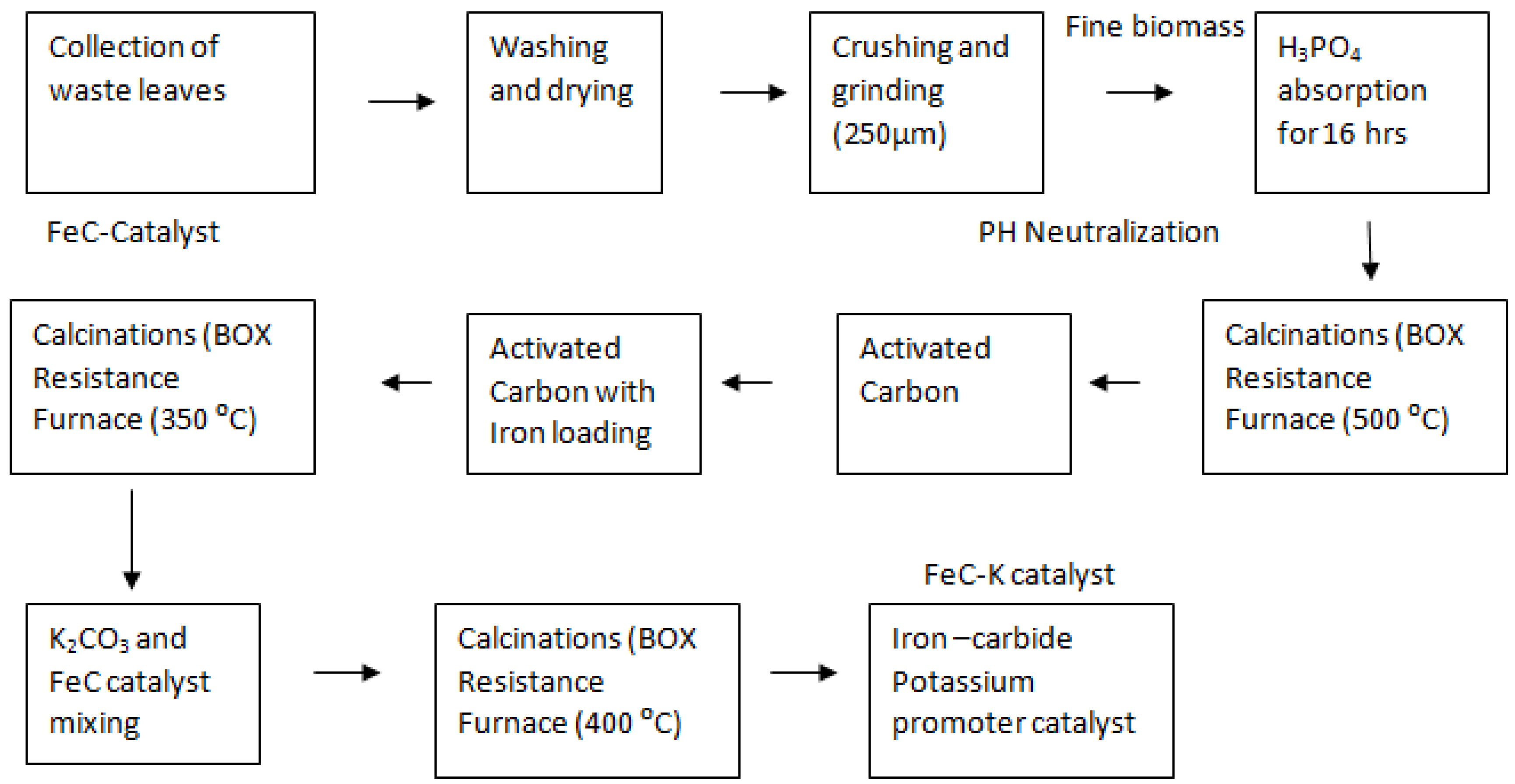
3.1. Preparation of Activated Carbon

The leftover leaves of “Lantana camara” (24 g) were collected from SMME Department, NUST Islamabad, (latitude, 33.6360821; longitude, 72.9897282) Pakistan. The surfaces of the leaves were cleaned three times with distilled water to remove dust. Before being crushed, the leaves were dried out in the open atmosphere for 3 to 4 days. The dried leaves were crushed and sieved. After that, an H3PO4 (wt 50%) solution was used to activate the fine biomass powder. The initial concentration of the H3PO4 solution was 85%. The required H3PO4 volumes per (17.38 g) dry raw biomass material were 12.13 mL [45]. The slurry-based material was calcined in a box resistance furnace for two hours at 500–600 degrees Celsius. Then, the obtained char was rinsed with distilled water to remove extra H3PO4 from the char [46]. After that, it was dried for an hour at 110°C to yield 4 g of activated carbon [45,46,47].

3.2. Catalyst Preparation

By incorporating 10% iron nitrate (3.2 g Fe (NO3)3.9H2O) and 4 g of “Lantana Camara”-activated carbon, the Fe-C sample was prepared. The sample was then calcined for three h at 350 °C in a box resistance furnace [48]. The prepared Fe-C catalyst was mixed with 3 wt% potassium carbonate (0.2675 g K2CO3) by adding 10 mL of deionized water dropwise and letting it sit at room temperature for a day to allow the potassium particles to properly soak into the Fe-C catalyst. In a box resistance furnace, the sample was calcined for three h at 400 °C [31]. The sample was maintained in an airtight sample bottle after cooling to room temperature. The procedures for making carbon-supported iron catalysts with and without potassium promoters are shown in Figure 9.

3.3. Catalyst Characterization

Various techniques were used to characterize the Fe-C and Fe-C-K catalysts. The surface area was examined using the Brunauer–Emmett–Teller method (SBET) (Micromeritics Gemini VII 2390t VI.03, Norcross, GA, USA). Energy dispersive X-ray analysis and a scanning electron microscope were used to assess changes in surface morphology (JEOL JSM 6490 LA, Akishima, Japan). The crystal structure was determined using the X-ray diffraction method (XRD-D8 advanced by Bruker, Bermen, Germany). The thermal deterioration was revealed by the TGA investigation (Model: DTG-60 H, TGA 5500 TA Instrument, New Castle, DE, USA).

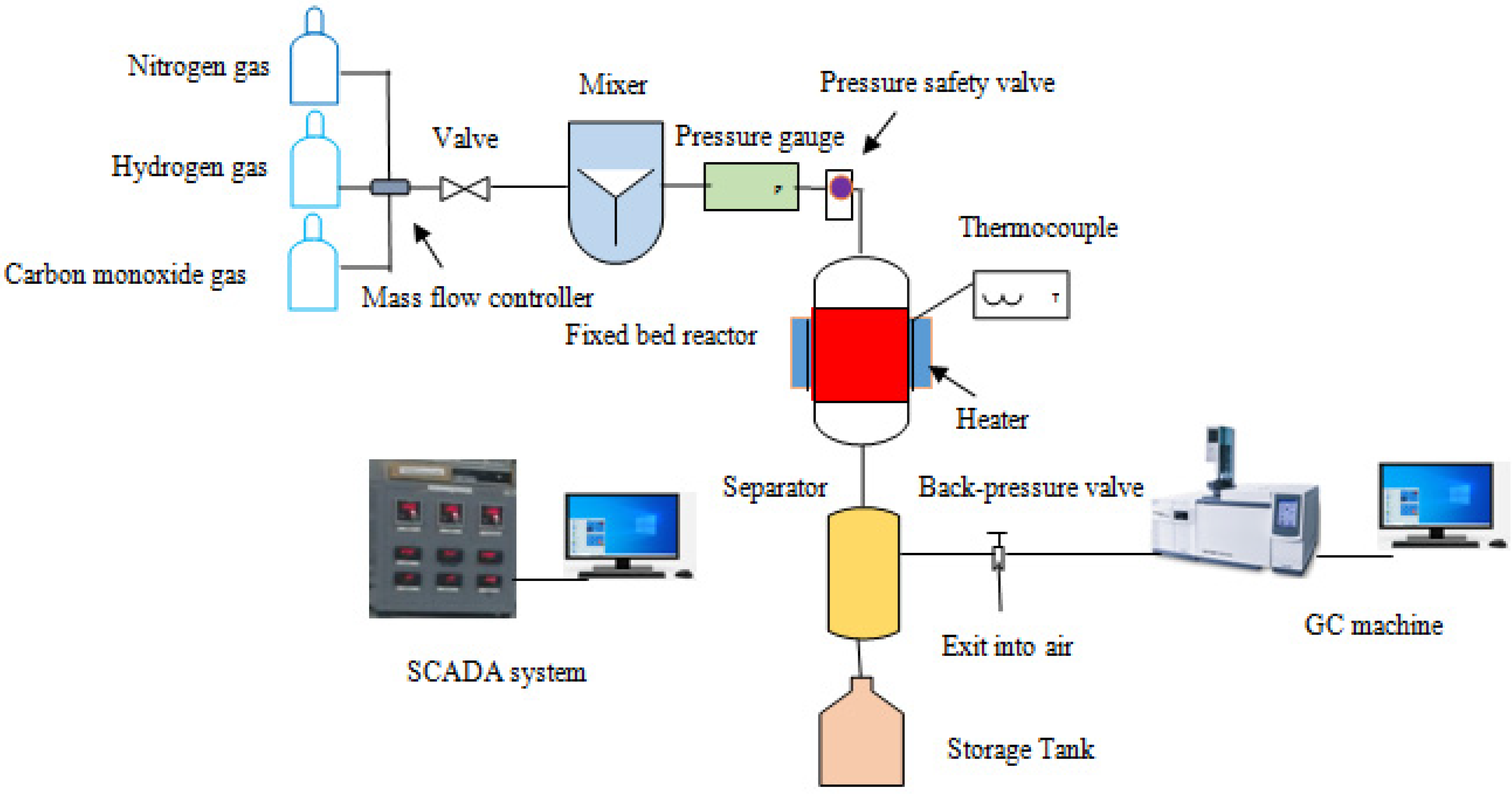
3.4. Catalyst Performance Test

A Fischer–Tropsch synthesis (FTS) system with a fixed-bed reactor was used to assess the catalytic performance. In the reactor, one gram of the prepared catalyst (Fe-C or Fe-C-K) was loaded. The catalyst was reduced for 5 h in a fixed bed reactor at 450 °C with a hydrogen gas flow of 30 sccm and a nitrogen gas flow of 10 sccm. The reactor was cooled to 350 °C to promote the reaction at 20 bar in the presence of a H2/CO (1:1 ratio). The pressure was controlled using a back-pressure regulator. A liquid product sample was taken from the two separators. Gas chromatography was used to evaluate the tail gases in real time (Shimadzu GC-2010 Plus, Kyoto, Japan). Gas chromatography–mass spectrometry was used to assess the liquid sample taken from the separator (GCMS-QP2020, Shimadzu Japan). The product selectivity was calculated using the peak area from the GCMS results. Figure 10 depicts the schematic diagram of the FTS plant that was employed in this experiment.

4. Conclusions

In this study, the effects of temperature and catalyst promoters on the formation of liquid hydrocarbons were studied. The Fe-C-K-supported catalyst with potassium promoter had 72 percent gasoline (C5–C11) selectivity at high temperatures. The GCMS results show the presence of C8+ hydrocarbons with selectivities of 96 percent and 91 percent when using a Fe-C-K catalyst at low and high temperatures. As a result, this research concludes that these catalysts may have a significant impact on the generation of gasoline and diesel in the future. Lantana Camara is composed of isocaryophyllene (16.7%), germacrene D (12.3%), bicyclogermacrene (19.4%), and valecene (12.9%), and caryophyllene isomers were detected in Lantana Camara’s essential oil composition. Because of the oily nature of “Lantana Camara,” the activated carbon utilized in the catalyst preparation had a significant impact on the increased hydrocarbon production. This research concludes that the use of activated carbon as a support made from Lantana Camara in FTS catalysts has a significant influence in improving hydrocarbon selectivity.

Author Contributions

Conceptualization, writing—original draft, formal analysis, M.A.; funding acquisition, S.M.W.; investigation, methodology, S.M.; project administration, resources, visualization, supervision, writing—review and editing, N.I., A.I. All authors have read and agreed to the published version of the manuscript.

Funding

Authors are grateful to the Researchers Supporting Project Number (RSP2022R448), King Saud University, Riyadh, Saudi Arabia.

Institutional Review Board Statement

Not applicable.

Informed Consent Statement

Not applicable.

Data Availability Statement

The data are presented in the present research article.

Acknowledgments

The work was conducted at the U.S.-Pakistan Center for Advanced Studies in Energy (USPCASE), NUST. The authors appreciate the technical support by the Energy Storage and Conservation lab staff and the Advanced Energy Materials lab. Authors are grateful to the Researchers Supporting Project Number (RSP2022R448), King Saud University, Riyadh, Saudi Arabia.

Conflicts of Interest

The authors declare no conflict of interest.

References

  1. Sharif, M.F.; Arslan, M.; Iqbal, N.; Ahmad, N.; Noor, T. Development of hydrotalcite based cobalt catalyst by hydrothermal and co-precipitation method for Fischer-Tropsch synthesis. Bull. Chem. React. Eng. Catal. 2017, 12, 357–363. [Google Scholar] [CrossRef]
  2. Amin, M.; Shah, H.H.; Fareed, A.G.; Khan, W.U.; Chung, E.; Zia, A.; Farooqi, Z.U.R.; Lee, C. Science Direct Hydrogen production through renewable and non- renewable energy processes and their impact on climate change. Int. J. Hydrogen Energy 2022, 47, 33112–33134. [Google Scholar] [CrossRef]
  3. Ma, G.; Wang, X.; Xu, Y.; Wang, Q.; Wang, J.; Lin, J.; Wang, H.; Dong, C.; Zhang, C.; Ding, M. Enhanced Conversion of Syngas to Gasoline-Range Hydrocarbons over Carbon Encapsulated Bimetallic FeMn Nanoparticles. ACS Appl. Energy Mater. 2018, 1, 4304–4312. [Google Scholar] [CrossRef]
  4. Martínez-Vargas, D.X.; Sandoval-Rangel, L.; Campuzano-Calderon, O.; Romero-Flores, M.; Lozano, F.J.; Nigam, K.D.P.; Mendoza, A.; Montesinos-Castellanos, A. Recent Advances in Bifunctional Catalysts for the Fischer-Tropsch Process: One-Stage Production of Liquid Hydrocarbons from Syngas. Ind. Eng. Chem. Res. 2019, 58, 15872–15901. [Google Scholar] [CrossRef]
  5. Dos Santos, R.G.; Alencar, A.C. Biomass-derived syngas production via gasification process and its catalytic conversion into fuels by Fischer Tropsch synthesis: A review. Int. J. Hydrogen Energy 2020, 45, 18114–18132. [Google Scholar] [CrossRef]
  6. Li, Y.; Lu, W.; Zhao, Z.; Zhao, M.; Lyu, Y.; Gong, L.; Zhu, H.; Ding, Y. Tuning surface oxygen group concentration of carbon supports to promote Fischer-Tropsch synthesis. Appl. Catal. A Gen. 2021, 613, 118017. [Google Scholar] [CrossRef]
  7. Xiong, H.; Jewell, L.L.; Coville, N.J. Shaped Carbons As Supports for the Catalytic Conversion of Syngas to Clean Fuels. ACS Catal. 2015, 5, 2640–2658. [Google Scholar] [CrossRef]
  8. Valero-Romero, M.J.; Rodríguez-Cano, M.Á.; Palomo, J.; Rodríguez-Mirasol, J.; Cordero, T. Carbon-Based Materials as Catalyst Supports for Fischer–Tropsch Synthesis: A Review. Front. Mater. 2021, 7, 617432. [Google Scholar] [CrossRef]
  9. Xiong, H.; Motchelaho, M.A.; Moyo, M.; Jewell, L.L.; Coville, N.J. Fischer-Tropsch synthesis: Iron-based catalysts supported on nitrogen-doped carbon nanotubes synthesized by post-doping. Appl. Catal. A Gen. 2014, 482, 377–386. [Google Scholar] [CrossRef]
  10. Chernyak, S.A.; Ivanov, A.S.; Maksimov, S.V.; Maslakov, K.I.; Isaikina, O.Y.; Chernavskii, P.A.; Kazantsev, R.V.; Eliseev, O.L.; Savilov, S.S. Fischer-Tropsch synthesis over carbon-encapsulated cobalt and iron nanoparticles embedded in 3D-framework of carbon nanotubes. J. Catal. 2020, 389, 270–284. [Google Scholar] [CrossRef]
  11. Barrios, A.J.; Gu, B.; Luo, Y.; Peron, D.V.; Chernavskii, P.A.; Virginie, M.; Wojcieszak, R.; Thybaut, J.W.; Ordomsky, V.V.; Khodakov, A.Y. Identification of efficient promoters and selectivity trends in high temperature Fischer-Tropsch synthesis over supported iron catalysts. Appl. Catal. B Environ. 2020, 273, 119028. [Google Scholar] [CrossRef]
  12. Gerber, I.C.; Serp, P. A Theory/Experience Description of Support Effects in Carbon-Supported Catalysts. Chem. Rev. 2020, 120, 1250–1349. [Google Scholar] [CrossRef] [PubMed]
  13. Yan, L.; Liu, J.; Wang, X.; Ma, C.; Zhang, C.; Wang, H.; Wei, Y.; Wen, X.; Yang, Y.; Li, Y. Ru catalysts supported by Si3N4 for Fischer-Tropsch synthesis. Appl. Surf. Sci. 2020, 526, 146631. [Google Scholar] [CrossRef]
  14. Liu, G.; Chen, Q.; Oyunkhand, E.; Ding, S.; Yamane, N.; Yang, G.; Yoneyama, Y.; Tsubaki, N. Nitrogen-rich mesoporous carbon supported iron catalyst with superior activity for Fischer-Tropsch synthesis. Carbon N. Y. 2018, 130, 304–314. [Google Scholar] [CrossRef]
  15. Chun, D.H.; Rhim, G.B.; Youn, M.H.; Deviana, D.; Lee, J.E.; Park, J.C.; Jeong, H. Brief Review of Precipitated Iron-Based Catalysts for Low-Temperature Fischer–Tropsch Synthesis. Top. Catal. 2020, 63, 793–809. [Google Scholar] [CrossRef]
  16. Xu, J.; Chen, L.; Qu, H.; Jiao, Y.; Xie, J.; Xing, G. Preparation and characterization of activated carbon from reedy grass leaves by chemical activation with H3PO4. Appl. Surf. Sci. 2014, 320, 674–680. [Google Scholar] [CrossRef]
  17. Liu, Y.; Yao, X.; Wang, Z.; Li, H.; Shen, X.; Yao, Z.; Qian, F. Synthesis of Activated Carbon from Citric Acid Residue by Phosphoric Acid Activation for the Removal of Chemical Oxygen Demand from Sugar-Containing Wastewater. Environ. Eng. Sci. 2019, 36, 656–666. [Google Scholar] [CrossRef] [Green Version]
  18. Gao, Y.; Yue, Q.; Gao, B.; Li, A. Insight into activated carbon from different kinds of chemical activating agents: A review. Sci. Total Environ. 2020, 746, 141094. [Google Scholar] [CrossRef]
  19. Teng, X.; Huang, S.; Wang, J.; Wang, H.; Zhao, Q.; Yuan, Y.; Ma, X. Fabrication of Fe2C Embedded in Hollow Carbon Spheres: A High-Performance and Stable Catalyst for Fischer-Tropsch Synthesis. ChemCatChem 2018, 10, 3883–3891. [Google Scholar] [CrossRef]
  20. Yang, X.; Zhang, H.; Liu, Y.; Ning, W.; Han, W.; Liu, H.; Huo, C. Preparation of iron carbides formed by iron oxalate carburization for fischer-tropsch synthesis. Catalysts 2019, 9, 347. [Google Scholar] [CrossRef]
  21. Chun, D.H.; Park, J.C.; Hong, S.Y.; Lim, J.T.; Kim, C.S.; Lee, H.; Yang, J.; Hong, S.J.; Jung, H. Highly selective iron-based Fischer-Tropsch catalysts activated by CO 2-containing syngas. J. Catal. 2014, 317, 135–143. [Google Scholar] [CrossRef] [Green Version]
  22. Lu, Y.; Yan, Q.; Han, J.; Cao, B.; Street, J.; Yu, F. Fischer–Tropsch synthesis of olefin-rich liquid hydrocarbons from biomass-derived syngas over carbon-encapsulated iron carbide/iron nanoparticles catalyst. Fuel 2017, 193, 369–384. [Google Scholar] [CrossRef] [Green Version]
  23. Zhao, Q.; Huang, S.; Han, X.; Chen, J.; Wang, J.; Rykov, A.; Wang, Y.; Wang, M.; Lv, J.; Ma, X. Highly active and controllable MOF-derived carbon nanosheets supported iron catalysts for Fischer-Tropsch synthesis. Carbon N. Y. 2021, 173, 364–375. [Google Scholar] [CrossRef]
  24. Tang, L.; He, L.; Wang, Y.; Chen, B.; Xu, W.; Duan, X.; Lu, A. Selective fabrication of χ-Fe5C2 by interfering surface reactions as a highly efficient and stable Fischer-Tropsch synthesis catalyst. Appl. Catal. B Environ. 2021, 284, 119753. [Google Scholar] [CrossRef]
  25. Lyu, S.; Wang, L.; Li, Z.; Yin, S.; Chen, J.; Zhang, Y.; Li, J.; Wang, Y. Stabilization of ε-iron carbide as high-temperature catalyst under realistic Fischer–Tropsch synthesis conditions. Nat. Commun. 2020, 11, 1–8. [Google Scholar] [CrossRef]
  26. Sun, B.; Xu, K.; Nguyen, L.; Qiao, M.; Tao, F.F. Preparation and Catalysis of Carbon-Supported Iron Catalysts for Fischer-Tropsch Synthesis. ChemCatChem 2012, 4, 1498–1511. [Google Scholar] [CrossRef]
  27. Einemann, M.; Neumann, F.; Thomé, A.G.; Wabo, S.G.; Roessner, F. Quantitative study of the oxidation state of iron-based catalysts by inverse temperature-programmed reduction and its consequences for catalyst activation and performance in Fischer-Tropsch reaction. Appl. Catal. A Gen. 2020, 602, 117718. [Google Scholar] [CrossRef]
  28. Shakeri, J.; Joshaghani, M.; Hadadzadeh, H.; Shaterzadeh, M.J. Methane carbonylation to light olefins and alcohols over carbon–based iron–and cobalt–oxide catalysts. J. Taiwan Inst. Chem. Eng. 2021, 122, 127–135. [Google Scholar] [CrossRef]
  29. Pérez, S.; Mondragón, F.; Moreno, A. Iron ore as precursor for preparation of highly active χ-Fe5C2 core-shell catalyst for Fischer-Tropsch synthesis. Appl. Catal. A Gen. 2019, 587, 117264. [Google Scholar] [CrossRef]
  30. Jiang, F.; Zhang, M.; Liu, B.; Xu, Y.; Liu, X. Insights into the influence of support and potassium or sulfur promoter on iron-based Fischer-Tropsch synthesis: Understanding the control of catalytic activity, selectivity to lower olefins, and catalyst deactivation. Catal. Sci. Technol. 2017, 7, 1245–1265. [Google Scholar] [CrossRef]
  31. Niu, L.; Liu, X.; Wen, X.; Yang, Y.; Xu, J.; Li, Y. Effect of potassium promoter on phase transformation during H2 pretreatment of a Fe2O3 Fischer Tropsch synthesis catalyst precursor. Catal. Today 2020, 343, 101–111. [Google Scholar] [CrossRef]
  32. Chen, Y.; Wei, J.; Duyar, M.S.; Ordomsky, V.V.; Khodakov, A.Y.; Liu, J. Carbon-based catalysts for Fischer-Tropsch synthesis. Chem. Soc. Rev. 2021, 50, 2337–2366. [Google Scholar] [CrossRef]
  33. Witoon, T.; Chaipraditgul, N.; Numpilai, T.; Lapkeatseree, V.; Ayodele, B.V.; Cheng, C.K.; Siri-Nguan, N.; Sornchamni, T.; Limtrakul, J. Highly active Fe-Co-Zn/K-Al2O3 catalysts for CO2 hydrogenation to light olefins. Chem. Eng. Sci. 2021, 233, 116428. [Google Scholar] [CrossRef]
  34. Amoyal, M.; Vidruk-Nehemya, R.; Landau, M.V.; Herskowitz, M. Effect of potassium on the active phases of Fe catalysts for carbon dioxide conversion to liquid fuels through hydrogenation. J. Catal. 2017, 348, 29–39. [Google Scholar] [CrossRef]
  35. Di, Z.; Feng, X.; Yang, Z.; Luo, M. Effect of Iron Precursor on Catalytic Performance of Precipitated Iron Catalyst for Fischer–Tropsch Synthesis Reaction. Catal. Letters 2020, 150, 2640–2647. [Google Scholar] [CrossRef]
  36. Wang, A.; Luo, M.; Lü, B.; Song, Y.; Li, M.; Yang, Z. Effect of Na, Cu and Ru on metal-organic framework-derived porous carbon supported iron catalyst for Fischer-Tropsch synthesis. Mol. Catal. 2021, 509, 111601. [Google Scholar] [CrossRef]
  37. Lu, F.; Chen, X.; Lei, Z.; Wen, L.; Zhang, Y. Revealing the activity of different iron carbides for Fischer-Tropsch synthesis. Appl. Catal. B Environ. 2021, 281, 119521. [Google Scholar] [CrossRef]
  38. Zhao, H.; Liu, J.; Yang, C.; Yao, S.; Su, H.; Gao, Z.; Dong, M.; Wang, J.; Rykov, A.I.; Wang, J.; et al. Synthesis of iron-carbide nanoparticles: Identification of the active phase and mechanism of fe-based fischer-tropsch synthesis. CCS Chem. 2021, 3, 2712–2724. [Google Scholar] [CrossRef]
  39. Cho, J.M.; Kim, B.G.; Han, G.Y.; Sun, J.; Jeong, H.K.; Bae, J.W. Effects of metal-organic framework-derived iron carbide phases for CO hydrogenation activity to hydrocarbons. Fuel 2020, 281, 118779. [Google Scholar] [CrossRef]
  40. Ma, W.; Kugler, E.L.; Dadyburjor, D.B. Promotional effect of copper on activity and selectivity to hydrocarbons and oxygenates for Fischer-Tropsch synthesis over potassium-promoted iron catalysts supported on activated carbon. Energy Fuels 2011, 25, 1931–1938. [Google Scholar] [CrossRef]
  41. Claeys, M.; van Steen, E. Basic studies. Stud. Surf. Sci. Catal. 2004, 152, 601–680. [Google Scholar] [CrossRef]
  42. Aluha, J.; Hu, Y.; Abatzoglou, N. Effect of CO concentration on the α-value of plasma-synthesized Co/C catalyst in Fischer-Tropsch synthesis. Catalysts 2017, 7, 69. [Google Scholar] [CrossRef] [Green Version]
  43. Sousa, E.O.; Colares, A.V.; Rodrigues, F.F.G.; Campos, A.R.; Lima, S.G.; Costa, J.M.G. Effect of Collection Time on Essential Oil Composition of Lantana camara Linn (Verbenaceae) Growing in Brazil Northeastern. 2010. Available online: http://www.acgpubs.org/RNP (accessed on 5 October 2022).
  44. Tafjord, J.; Rytter, E.; Holmen, A.; Myrstad, R.; Svenum, I.; Christensen, B.E.; Yang, J. Transition-Metal Nanoparticle Catalysts Anchored on Carbon Supports via Short-Chain Alginate Linkers. ACS Appl. Nano Mater. 2021, 4, 3900–3910. [Google Scholar] [CrossRef]
  45. Amin, M.; Shah, H.H.; Iqbal, A.; Farooqi, Z.U.R.; Krawczuk, M.; Zia, A. Conversion of Waste Biomass into Activated Carbon and Evaluation of Environmental Consequences Using Life Cycle Assessment. Appl. Sci. 2022, 12, 5741. [Google Scholar] [CrossRef]
  46. Kumar, A.; Jena, H.M. Preparation and characterization of high surface area activated carbon from Fox nut (Euryale ferox) shell by chemical activation with H3PO4. Results Phys. 2016, 6, 651–658. [Google Scholar] [CrossRef] [Green Version]
  47. Amin, M.; Chung, E.; Shah, H.H. Effect of different activation agents for activated carbon preparation through characterization and life cycle assessment. Int. J. Environ. Sci. Technol. 2022, 1–12. [Google Scholar] [CrossRef]
  48. Zhao, X.; Lv, S.; Wang, L.; Li, L.; Wang, G.; Zhang, Y.; Li, J. Comparison of preparation methods of iron-based catalysts for enhancing Fischer-Tropsch synthesis performance. Mol. Catal. 2018, 449, 99–105. [Google Scholar] [CrossRef]
Figure 1. XRD pattern: (A) activated carbon; (B) Fe-C catalyst, Fe-C LT-FTS, and Fe-C HT-FTS; (C) Fe-C-K catalyst, Fe-C-K LT-FTS, and Fe-C-K HT-FTS.
Catalysts 12 01234 g001
Figure 2. Scanning electron microscopy of prepared activated carbon (a,b) Lantana Camara.
Catalysts 12 01234 g002
Figure 3. Scanningelectron microscopy of Fe-C catalyst (a), Fe-C LT-FTS (b), and Fe-C HT-FTS (c).
Catalysts 12 01234 g003
Figure 4. Scanning electron microscopy of Fe-C-K catalyst (a), Fe-C-K LT-FTS (b), and Fe-C-K HT-FTS (c).
Catalysts 12 01234 g004
Figure 5. TGA analysis of activated carbon (a), Fe-C catalyst (b), Fe-C LT-FTS (c), Fe-C HT-FTS (d), Fe-C-K catalyst (e), Fe-C-K LT-FTS (f), and Fe-C-K HT-FTS (g).
Catalysts 12 01234 g005
Figure 6. Mechanism of a carbon-supported iron catalyst containing potassium as a promoter.
Catalysts 12 01234 g006
Figure 7. Sample collection.
Catalysts 12 01234 g007
Figure 8. Product composition: (a) Fe-C (LT-FTS), (b) Fe-C (HT-FTS), (c) Fe-C-K (LT-FTS), and (d) Fe-C-K (HT-FTS).
Catalysts 12 01234 g008
Figure 9. Synthesis of activated carbon-based catalyst by wet impregnation process.
Catalysts 12 01234 g009
Figure 10. Schematic diagram of the FTS setup.
Catalysts 12 01234 g010
Table 1. EDS elemental composition of FTS catalyst and activated carbon.
Compound NameEDS Analysis (Wt %)
Phosphorus (%)Carbon (%)Oxygen (%)Iron(%)Potassium (%)
Activated Carbon17.977.54.60.00.0
Fe-C10.515.055.517.00.0
Fe-C (LT-FTS)6.728.142.522.60.0
Fe-C (HT-FTS)4.551.340.04.00.0
Fe-C-K12.213.348.921.33.8
Fe-C-K (LT-FTS)9.110.346.924.94.1
Fe-C-K (HT-FTS)1.069.817.08.43.5
Table 2. BET surface area of activated carbon, Fe-C, and Fe-C-K catalyst.
Sample IDBET Surface Area (m2/g)
Activated Carbon167.4
Fe-C78.7
Fe-C-K11.1
Table 3. Distribution of carbon chain with oxygenates and non-oxygenates.
Sample IDDistribution of Carbon Chain (%)Oxygenates (%)Non-Oxygenates (%)
C2–C4C5–C11C12–C22>C23C8+
Light HydrocarbonsGasolineDieselLubricating Oil
Fe-C (LT-FTS)9.6726.4160.843.0881.3446.4053.60
Fe-C-K (LT-FTS)0.7816.9980.052.1896.5918.3081.70
Fe-C (HT-FTS)9.6036.4947.756.1680.2333.5066.50
Fe-C-K (HT-FTS)0.0372.5127.280.1891.4317.2082.80
Table 4. Hydrocarbon selectivity of different Fe-carbon-supported catalysts.
Sample NameTemperature (°C)Pressure (MPa)H2/CO RatioHydrocarbon SelectivityRef
C1–4C5+
Fe (carbon-based iron catalyst)22022:167.1631.20[28]
Fe/15C (carbon support)34021:161.039.0[44]
Fe-AC (AC=activated carbon)30022:146.353.7[8]
Fe/N-CNT-h (CNT=carbon nanotube)2750.82:139.160.9[9]
Fe/AC ((AC=activated carbon)34011:137.762.3[23]
FeOx(carbon-supported)26011:135.664.4[5]
Fe-1200(carbon-encapsulated)30021:131.268.8[10]
Fe(4700)(MOF-based Fe-catalyst)30021:124.375.7[39]
Fe/AC (activated carbon)20021:19.6790.33This work
Fe/AC (activated carbon)35021:19.6090.40This work
Publisher’s Note: MDPI stays neutral with regard to jurisdictional claims in published maps and institutional affiliations.

