
Electrocatalysts Based on Novel Carbon Forms for the Oxidation of Sulphite


 ,
, 
Abstract
1. Introduction
2. Results
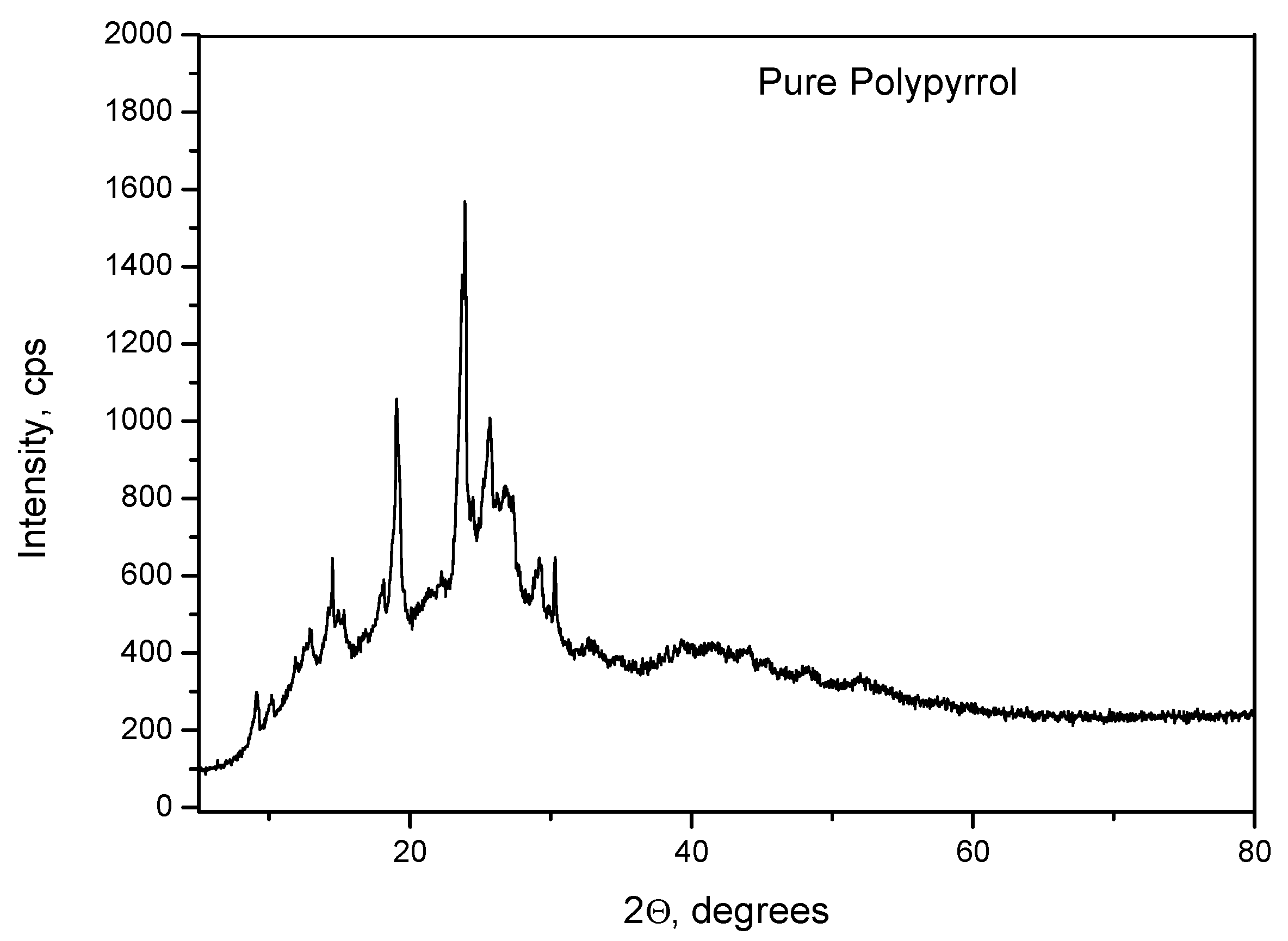
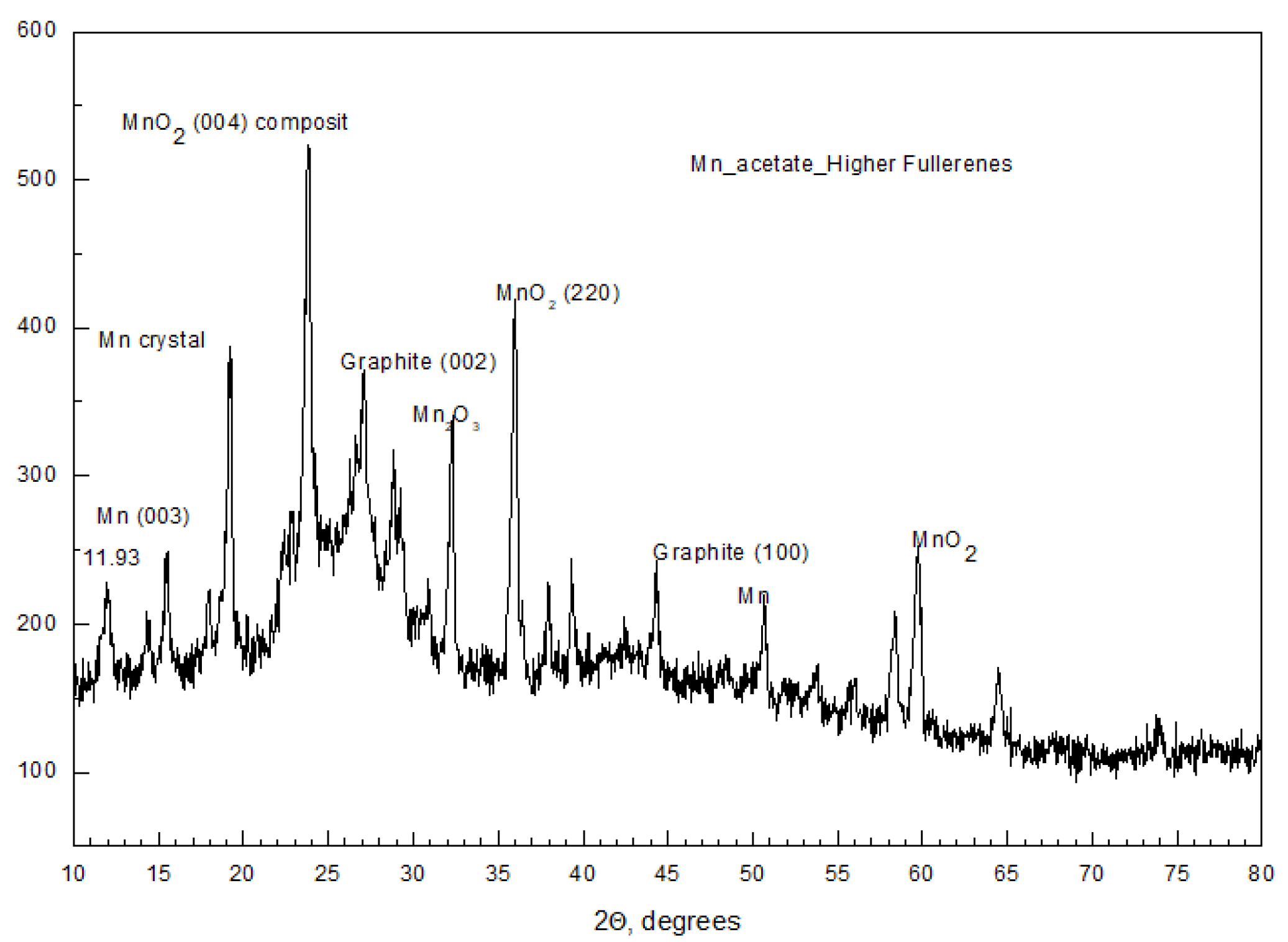
2.1. XRD Studies
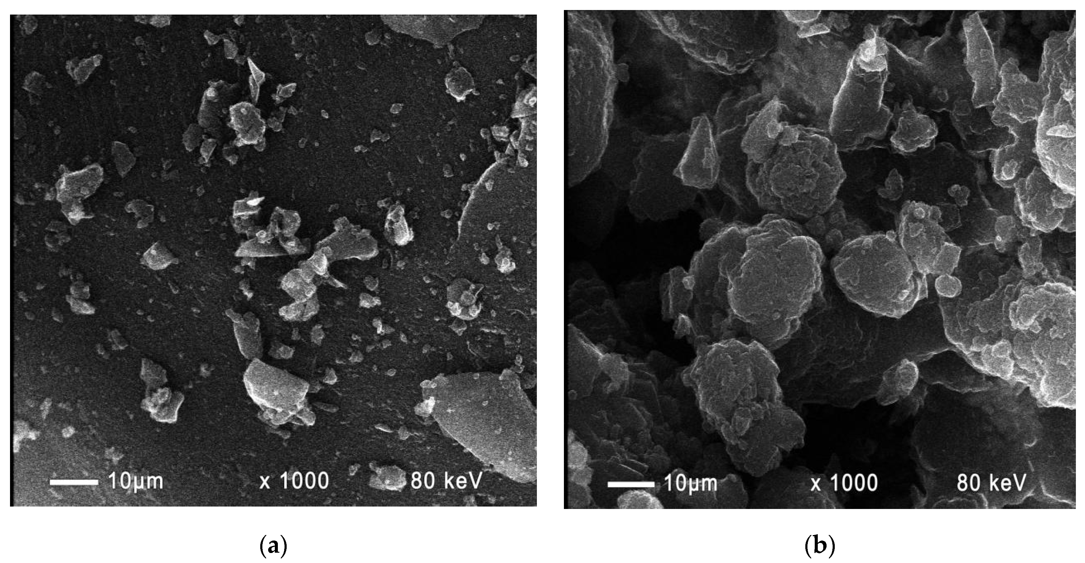
2.2. SEM Photographs
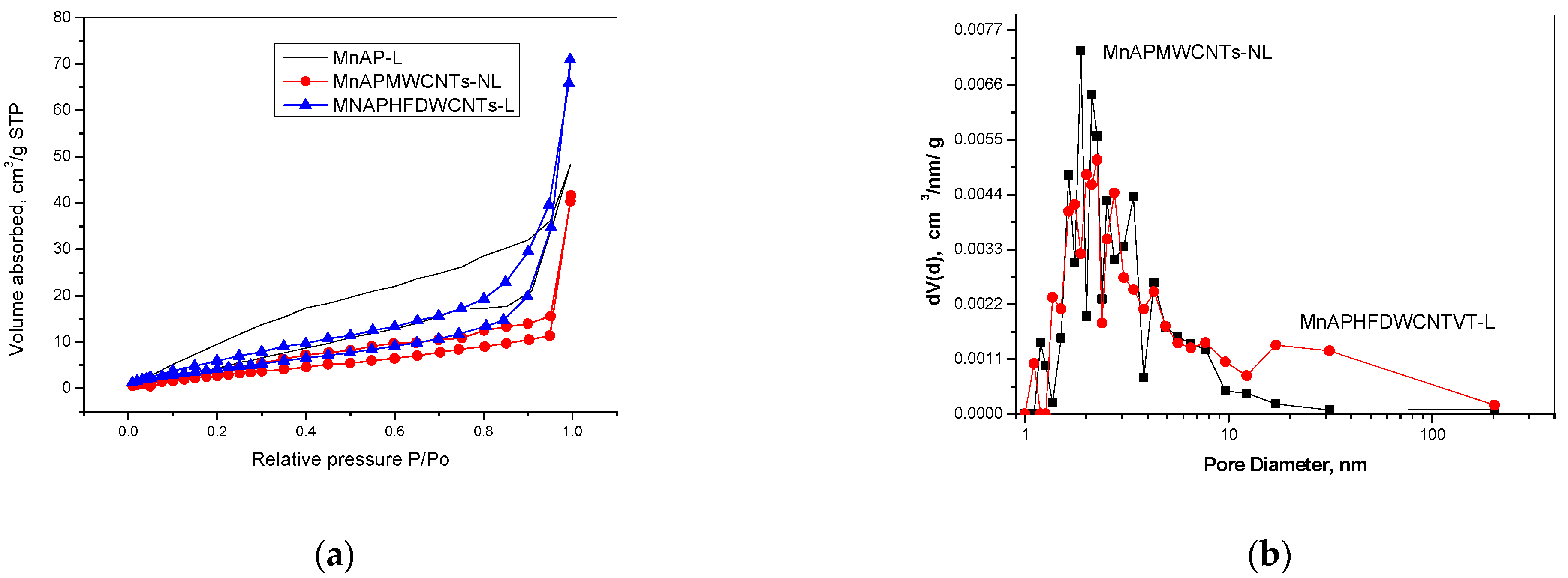
2.3. BET Surface Area and Pore Size Analysis
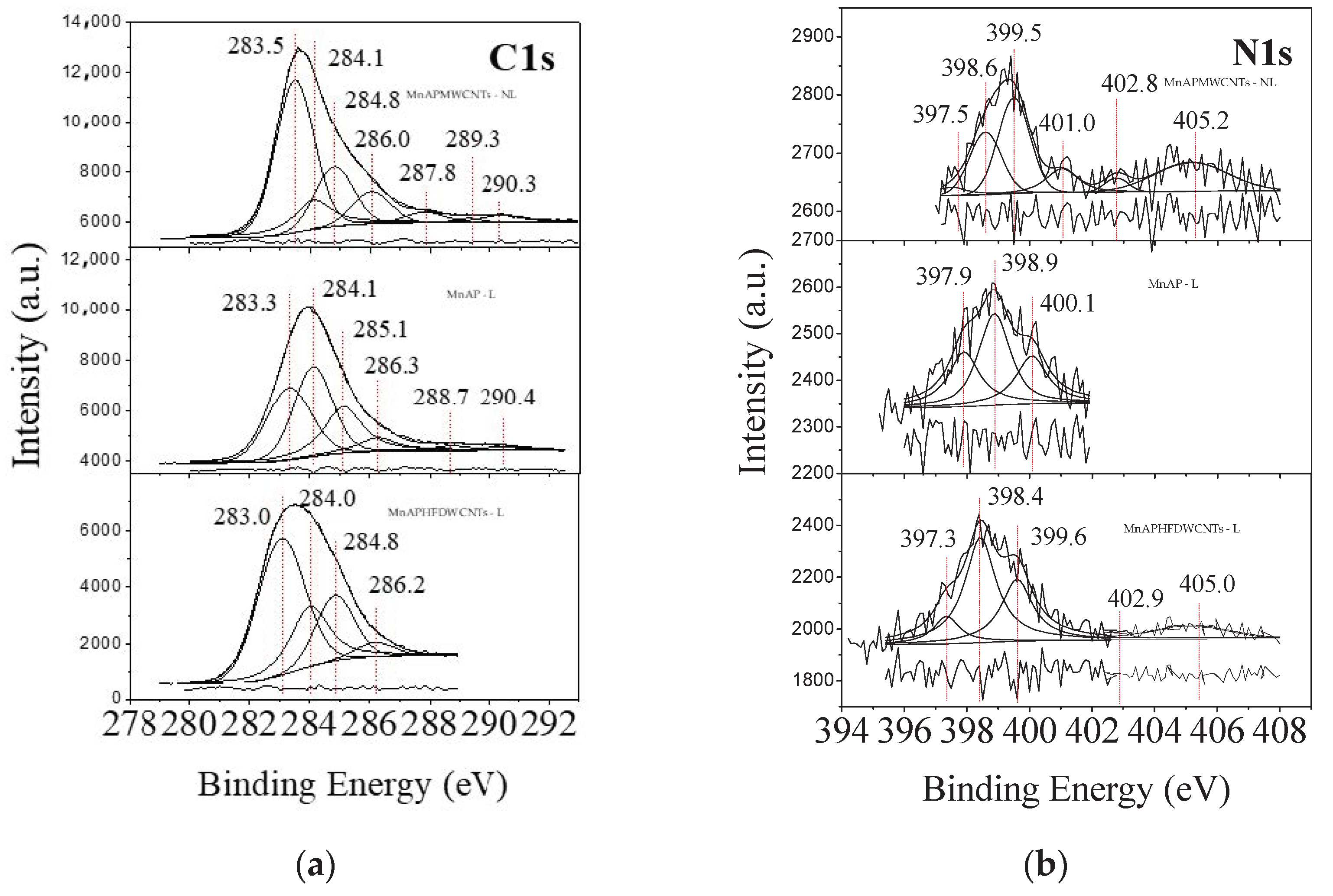
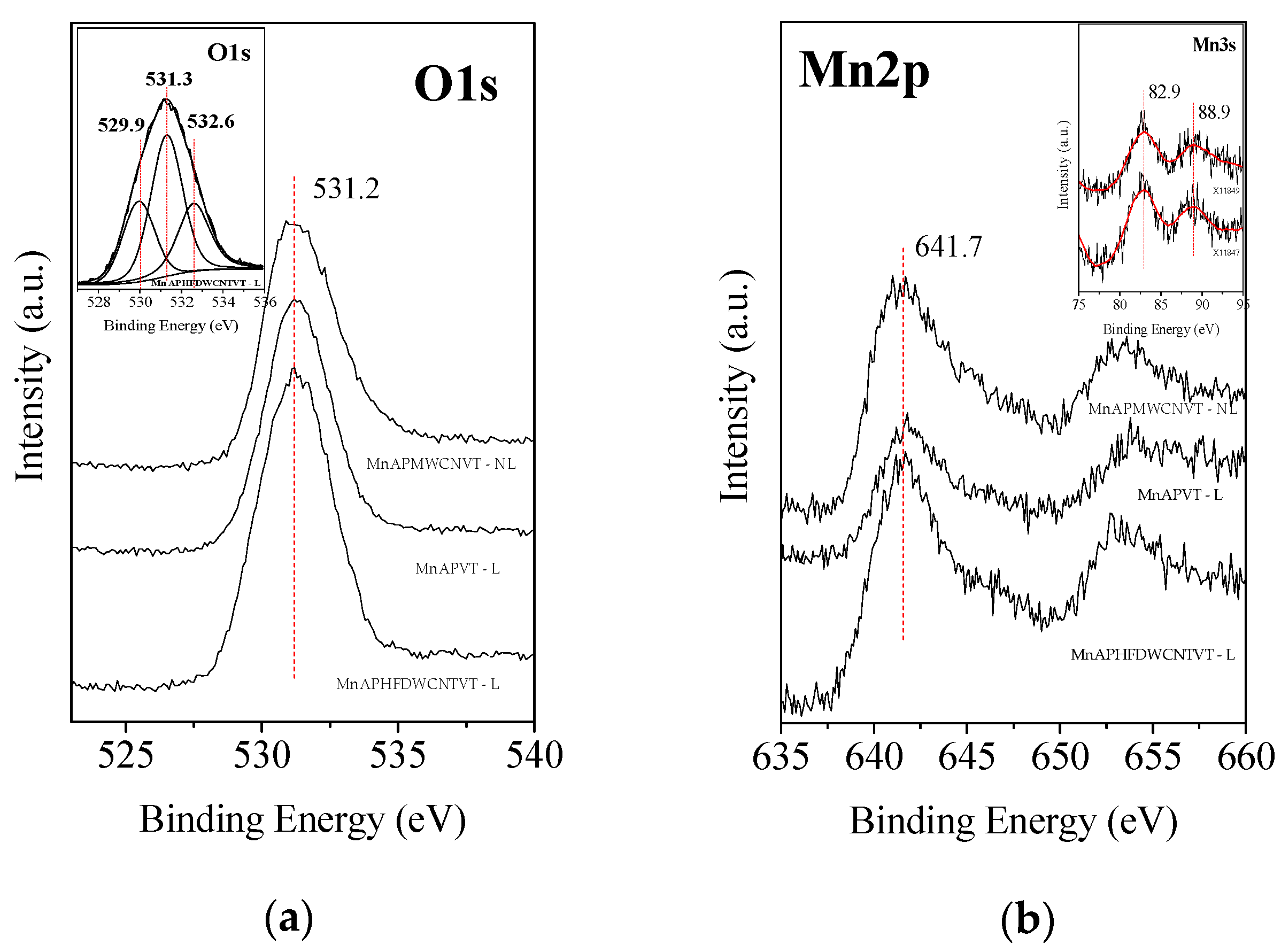
2.4. XPS Studies
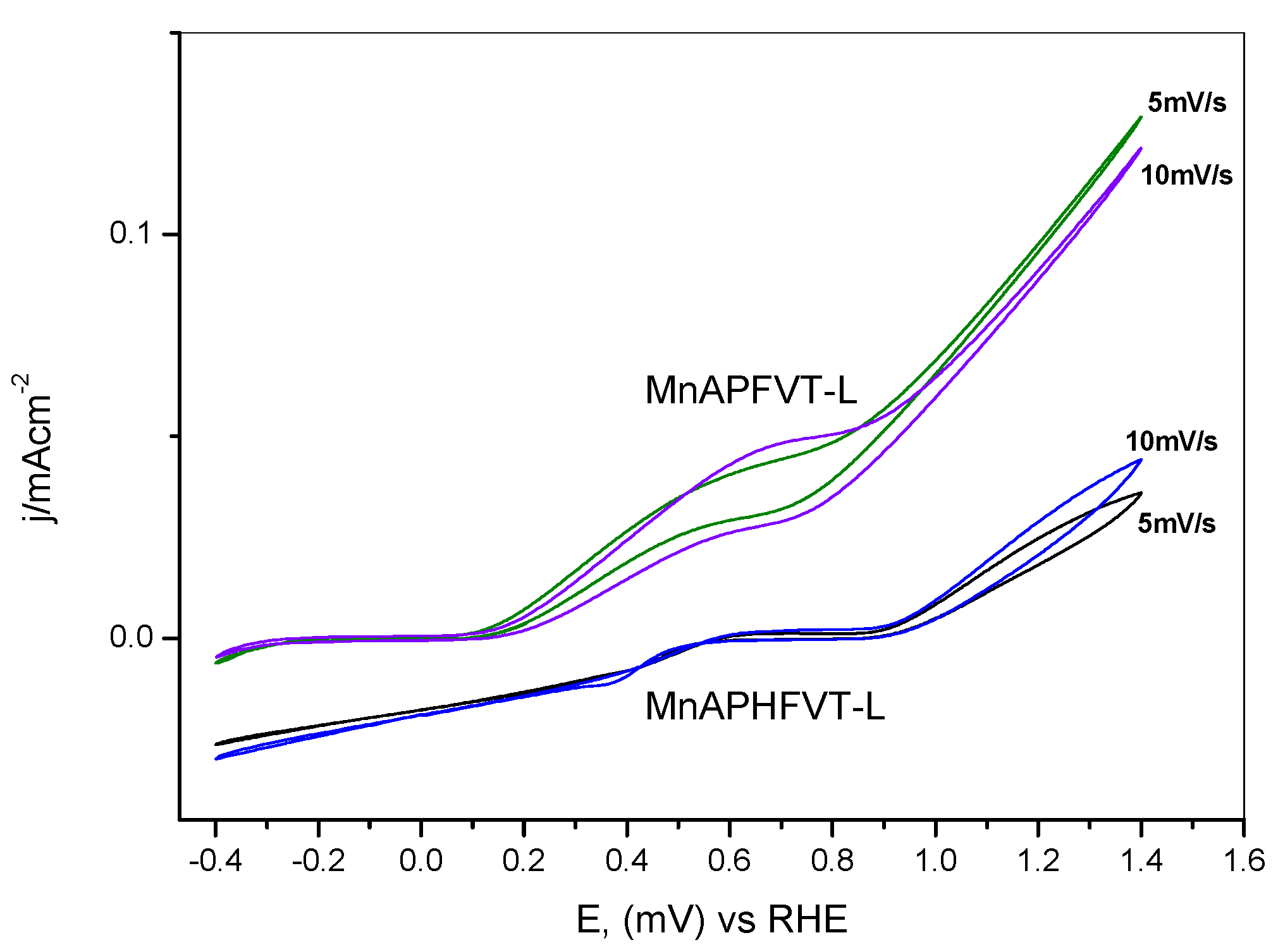
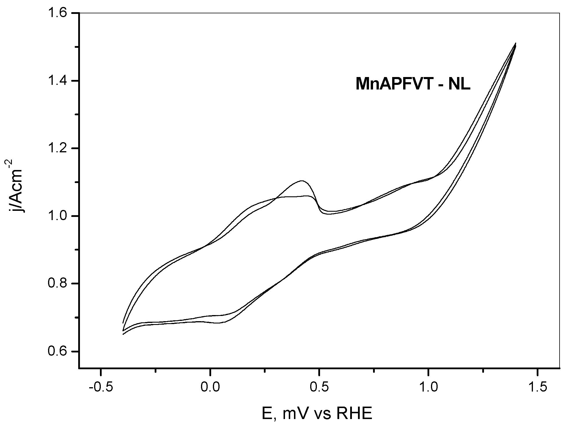
2.5. Cyclic Voltammetry Studies
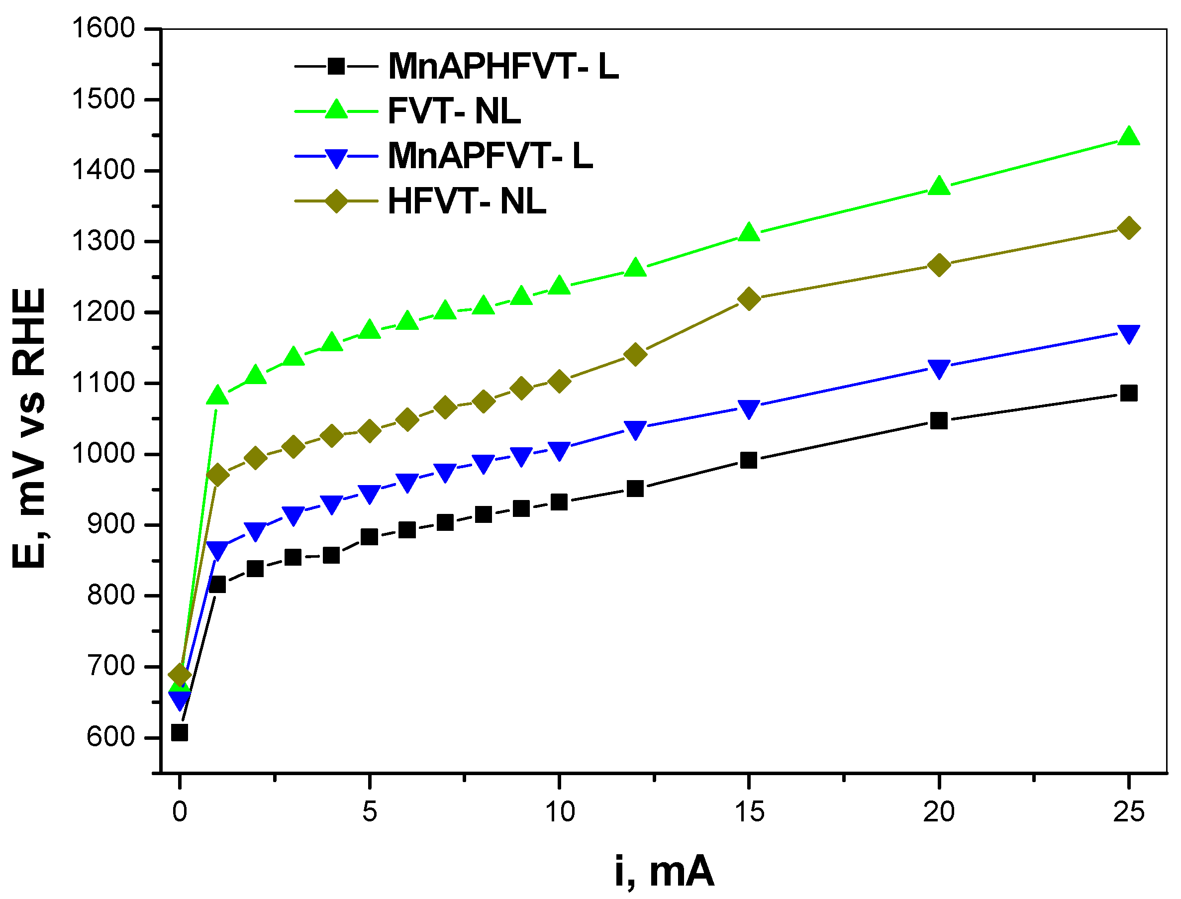
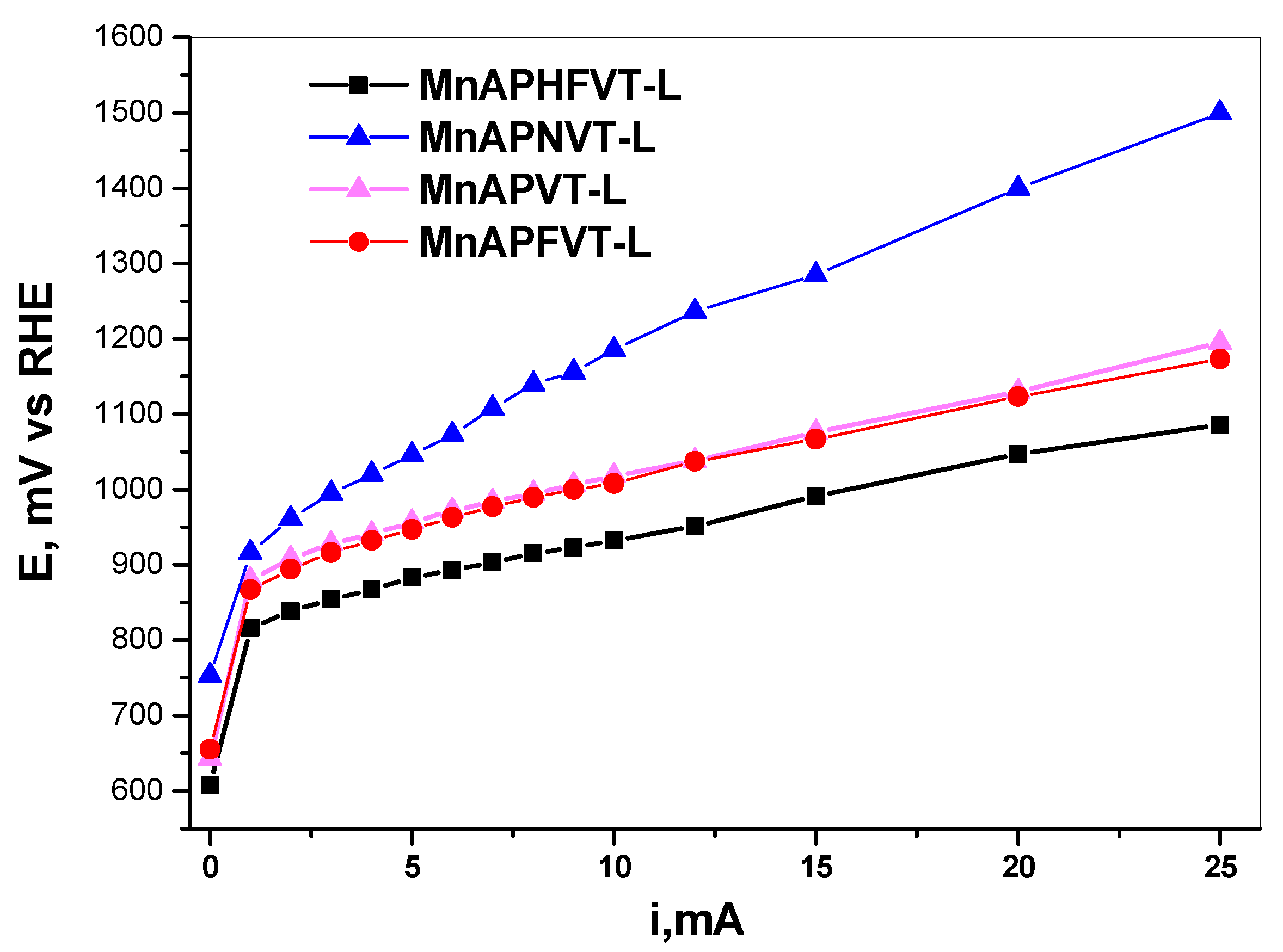
2.6. Polarization Curve Analysis
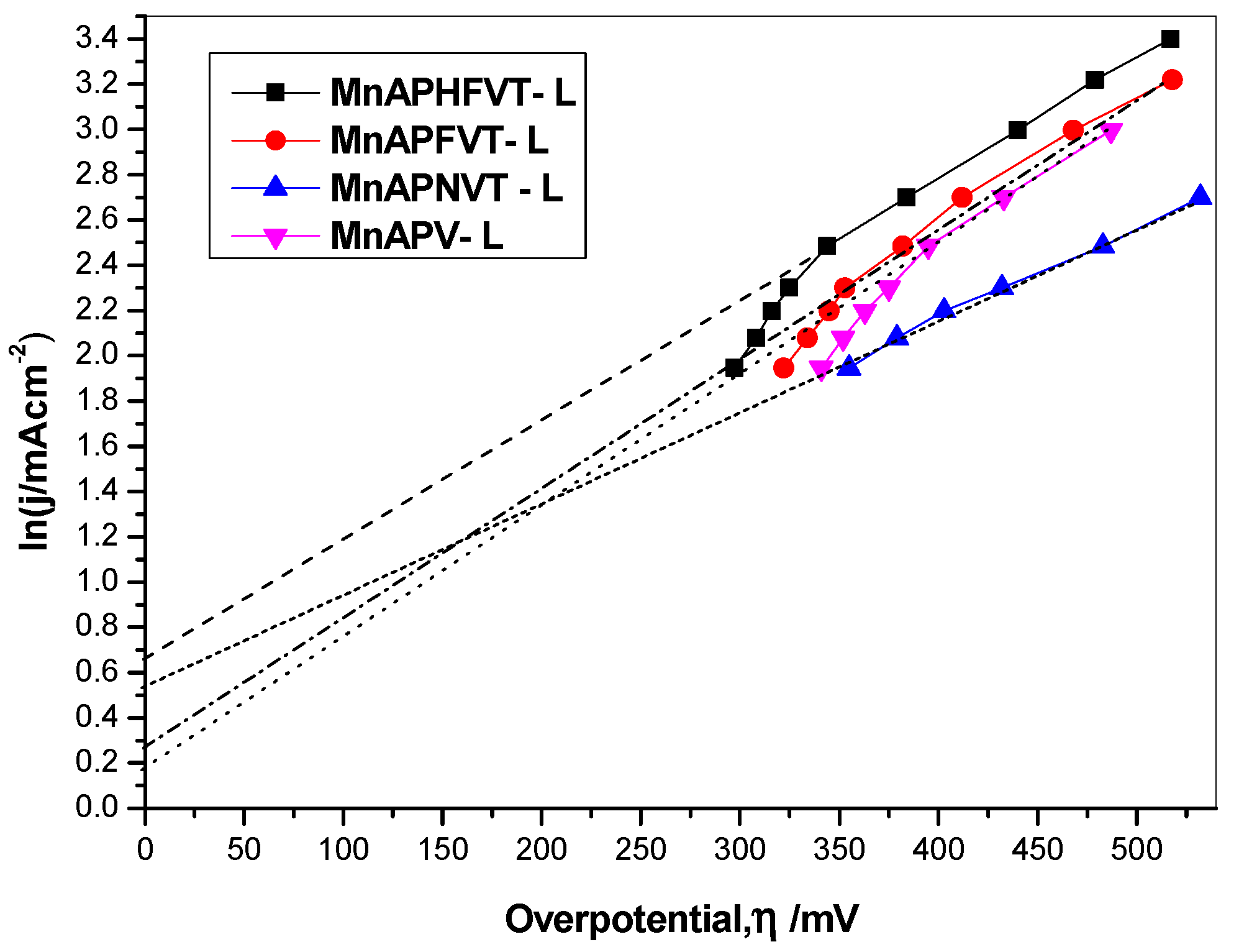
2.7. Tafel Analysis
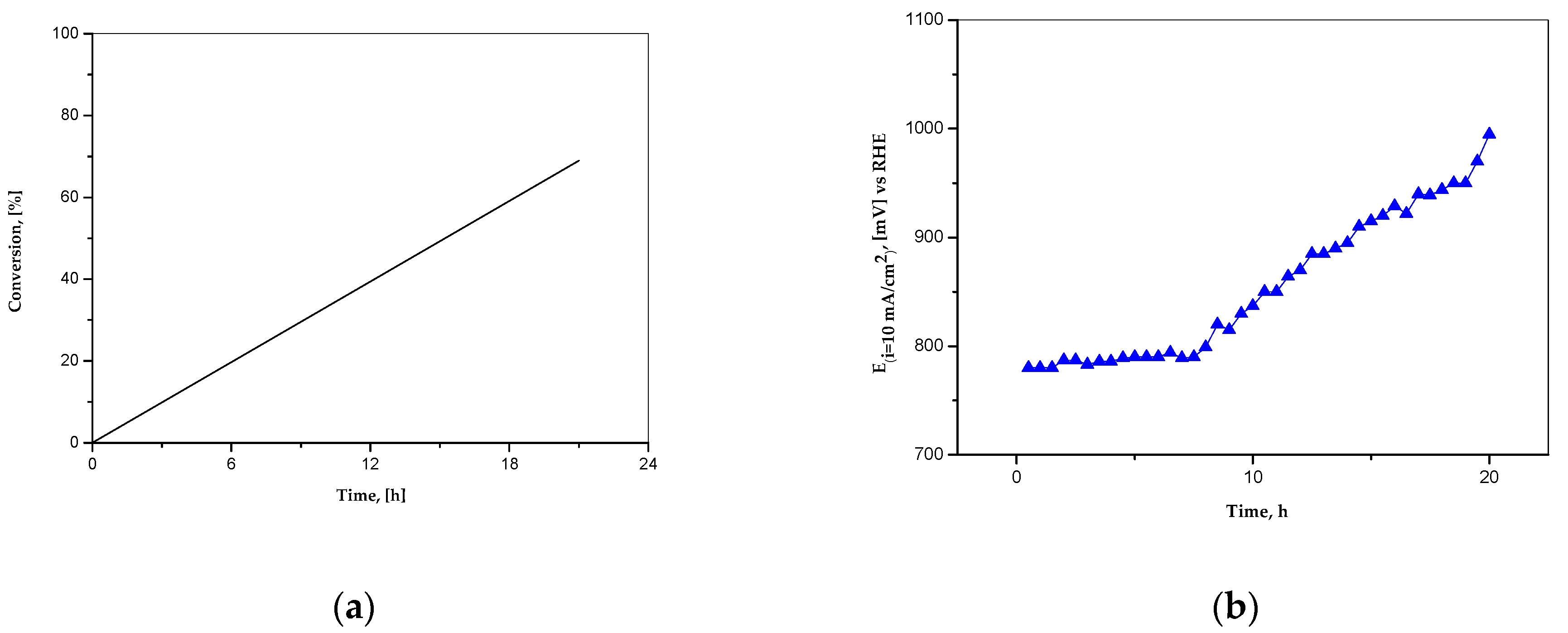
2.8. Dependence of the Anode Potential with Time at a Constant Current Density
3. Discussion
4. Materials and Methods
4.1. Reactions and Experiment
4.2. Catalyst Synthesis
4.3. Electrode Preparation
4.4. Experimental Equipment and Conditions
5. Conclusions
Author Contributions
Funding
Acknowledgments
Conflicts of Interest
References
- Lewis, G.N.; Randall, M.A. Preliminary study of reversible reactions of sulfur compounds. J. Am. Chem. Soc. 1918, 40, 356–362. [Google Scholar] [CrossRef][Green Version]
- Bancroft, W.D.; Magoffin, J.E. Energy Levels in Electro-chemistry. J. Am. Chem. Soc. 1935, 57, 2561. [Google Scholar] [CrossRef]
- Coursier, J. Interprétation des mesures potentiométriques au moyen des courbes de polarisation. Anal. Chim. Acta 1952, 7, 77–94. [Google Scholar] [CrossRef]
- Bancroft, W.D. Anode reactions. Trans. Electrochem. Soc. 1937, 33, 195–205. [Google Scholar] [CrossRef]
- Bard, A.J. (Ed.) Encyclopedia of Electrochemistry of the Elements; Marcel Dekker, Inc.: New York, NY, USA, 1975; Volume IV, Chapter 6; p. 275. ISBN 0-8247-2504-2. [Google Scholar]
- Bouroushian, M. Electrochemistry of Metal Chalcogenides; Springer: Heidelberg/Berlin, Germany, 2010. [Google Scholar]
- Dribinskii, A.V.; Tarasevich, M.R.; Kazarinov, V.E. Electrocatalysis on carbon materials. Mater. Chem. Phys. 1989, 22, 377–400. [Google Scholar] [CrossRef]
- Hunger, T.; Lapicque, F.; Storck, A. Electrochemical oxidation of sulphite ions at graphite electrodes. J. Appl. Electrochem. 1991, 21, 588–596. [Google Scholar] [CrossRef]
- Sun, H.Q.; Liu, S.Z.; Zhou, G.L.; Ang, H.M.; Tade, M.O.; Wang, S.B. Reduced graphene oxide for catalytic oxidation of aqueous organic pollutants. ACS Appl. Mater. Interfaces 2012, 4, 5466–5471. [Google Scholar] [CrossRef]
- Kong, X.K.; Chen, C.L.; Chen, Q.W. Doped graphene for metal-free catalysis. Chem. Soc. Rev. 2014, 43, 2841–2857. [Google Scholar] [CrossRef] [PubMed]
- Frank, B.; Blume, R.; Rinaldi, A.; Trunschke, A.; Schlogl, R. Oxygen Insertion Catalysis by sp2 Carbon. Angew. Chem. Int. Ed. 2011, 50, 10226–10230. [Google Scholar] [CrossRef]
- Frank, B.; Zhang, J.; Blume, R.; Schlogl, R.; Su, D.S. Heteroatoms increase the selectivity in oxidative dehydrogenation reactions on nanocarbons. Angew. Chem. Int. Ed. 2009, 48, 6913–6917. [Google Scholar] [CrossRef]
- Zhang, J.; Liu, X.; Blume, R.; Zhang, A.H.; Schlogl, R.; Su, D.S. Surface-modified carbon nanotubes catalyze oxidative dehydrogenation of n-butane. Science 2008, 322, 73–77. [Google Scholar] [CrossRef] [PubMed]
- Oh, W.D.; Dong, Z.; Lim, T.T. Generation of sulfate radical through heterogeneous catalysis for organic contaminants removal: Current development, challenges and prospects. Appl. Catal. B Environ. 2016, 194, 169–201. [Google Scholar] [CrossRef]
- Liu, S.Z.; Peng, W.C.; Sun, H.Q.; Wang, S.B. Physical and chemical activation of reduced graphene oxide for enhanced adsorption and catalytic oxidation. Nanoscale 2014, 6, 766–771. [Google Scholar] [CrossRef]
- Jiang, D.E.; Sumpter, B.G.; Dai, S.J. Unique chemical reactivity of a graphene nanoribbon’s zigzag edge. Chem. Phys. 2007, 126, 134701. [Google Scholar] [CrossRef]
- Zhao, Y.; Yang, L.J.; Chen, S.; Wang, X.Z.; Ma, Y.W.; Wu, Q.; Jiang, Y.F.; Qian, W.J.; Hu, Z.J. Can boron and nitrogen co-doping improve oxygen reduction reaction activity of carbon nanotubes? Am. Chem. Soc. 2013, 135, 1201–1204. [Google Scholar] [CrossRef] [PubMed]
- Bennett, J.E.; Gilbert, B.C.; Stell, J.K. Mechanisms of Peroxide Decomposition. EPR Studies of the One-electron Oxidation of the Peroxymonosulphate Anion (HOOSO3−) and the Reactions of SO5−. J. Chem. Soc. Perkin Trans. 1991, 2, 1105–1110. [Google Scholar] [CrossRef]
- Gilbert, B.C.; Stell, J.K. Mechanisms of peroxide decomposition. An ESR study of the reactions of the peroxomonosulphate anion (HOOSO 3‒) with Ti III, Fe II, and α-oxygen-substituted radicals. J. Chem. Soc. Perkin Trans. 1990, 2, 1281–1288. [Google Scholar] [CrossRef]
- Gilbert, B.C.; Stell, J.K. Mechanisms of peroxide decomposition: An electron paramagnetic resonance study of the reaction of the peroxomonosulphate anion (HOOSO–3) with Cu I. A marked contrast in behaviour with that of TiIII and FeII. J. Chem. Soc. Faraday Trans. 1990, 86, 3261–3266. [Google Scholar] [CrossRef]
- Bartlett, P.N. Electrochemistry of Carbon Electrodes (Band 16) in Advances in Electrochemical Sciences and Engineering; Richard, C., Lipkowski, J., Eds.; Wiley-VCH: Weinheim, Germany, 2015. [Google Scholar]
- van Veen, J.A.R.; van Baar, J.F.; Kroese, K.J. Effect of heat treatment on the performance of carbon-supported transition-metal chelates in the electrochemical reduction of oxygen. J. Chem. Soc. Faraday Trans. 1981, 177, 2827–2843. [Google Scholar] [CrossRef]
- Gupta, S.; Tryk, D.; Bae, I.; Aldred, W.; Yeager, E. Heat-treated polyacrylonitrile based catalysts for oxygen electroreduction. J. Appl. Electrochem. 1989, 19, 19–27. [Google Scholar] [CrossRef]
- Zhou, Y.; Neyerlin, K.; Olson, T.S.; Pylypenko, S.; Bult, J.; Dinh, H.N.; Gennett, T.; Shao, Z.; O’Hayre, R. Enhancement of Pt and Pt-alloy fuel cell catalyst activity and durability via nitrogen-modified carbon supports. Energy Environ. Sci. 2010, 3, 1437–1446. [Google Scholar] [CrossRef]
- Pylypenko, S.; Borisevich, A.; More, K.L.; Corpuz, A.R.; Holme, T.; Dameron, A.A.; Olson, T.S.; Dinh, H.N.; Gennett, T.; O’Hayre, R. Nitrogen: Unraveling the secret to stable carbon-supported Pt-alloy electrocatalysts. Energy Environ. Sci. 2013, 6, 2957–2964. [Google Scholar] [CrossRef]
- Titirici, M.M.; White, R.J.; Brun, N.; Budarin, V.L.; Su, D.S.; del Monte, F.; Clark, J.H.; MacLachlan, M.J. Sustainable carbon materials. Chem. Soc. Rev. 2015, 44, 250–290. [Google Scholar] [CrossRef] [PubMed]
- Wang, H.; Maiyalagan, T.; Wang, X. Review on recent progress in nitrogendoped graphene: Synthesis, characterization, and its potential applications. ACS Catal. 2012, 2, 781–794. [Google Scholar] [CrossRef]
- Czerw, R.; Terrones, M.; Charlier, J.C.; Blase, X.; Foley, B.; Kamalakaran, R.; Grobert, N.; Terrones, H.; Tekleab, D.; Ajayan, P.M.; et al. Identification of electron donor states in N-doped carbon nanotubes. Nano Lett. 2001, 1, 457–460. [Google Scholar] [CrossRef]
- Wood, K.N.; O’Hayre, R.; Pylypenko, S. Recent progress on nitrogen/carbon structures designed for use in energy and sustainability applications. Energy Environ. Sci. 2014, 7, 1212–1249. [Google Scholar] [CrossRef]
- Unni, S.M.; Dhavale, V.M.; Pillai, V.K.; Kurungot, S. High Pt Utilization Electrodes for Polymer Electrolyte Membrane Fuel Cells by Dispersing Pt Particles Formed by a Preprecipitation Method on Carbon “Polished” with Polypyrrole. J. Phys. Chem. C 2010, 114, 14654–14661. [Google Scholar] [CrossRef]
- Olson, T.S.; Pylypenko, S.; Atanassov, P.; Asazawa, K.; Yamada, K.; Tanaka, H. Anion-Exchange Membrane Fuel Cells: Dual-Site Mechanism of Oxygen Reduction Reaction in Alkaline Media on Cobalt–Polypyrrole Electrocatalysts. J. Phys. Chem. C 2010, 114, 5049–5059. [Google Scholar] [CrossRef]
- Ralph, T.R.; Hogarth, M.P. Catalysis for low-temperature fuel cells—Part 1: The cathode challenges. Plat. Met. Rev. 2002, 46, 4–15. [Google Scholar]
- Wang, J.; Wang, G.; Miao, S.; Liab, J.; Bao, X. Graphene -supported iron-based nanoparticles encapsulated in nitrogen-doped carbon as a synergistic catalyst for hydrogen evolution and oxygen reduction reactions. Faraday Discuss 2014, 176, 135–151. [Google Scholar] [CrossRef]
- Lambin, P.; Loiseau, A.; Culot, C.; Biro, L. Structure of carbon nanotubes probed by local and global probes. Carbon 2002, 40, 1635–1648. [Google Scholar] [CrossRef]
- Walanda, D.K.; Lawrance, G.A.; Donne, S.W. Hydrothermal MnO2: Synthesis, structure, morphology and discharge performance. J. Power Sources 2005, 139, 325–341. [Google Scholar] [CrossRef]
- Pchelarov, G.; Uzun, D.; Razkazova-Velkova, E.; Petrov, K. Oxidation of Sulphites by Electrodes Made of Novel Materials for Use in Microbial Fuel Cells. Biomed. J. Sci. Tech. Res. 2020, 26, 20137–20140. [Google Scholar]
- Brunauer, A.S.; Emmett, P.H.; Teller, E. Adsorption of gases in multimolecular layers. J. Am. Chem. Soc. 1938, 60, 309–319. [Google Scholar] [CrossRef]
- Niyogi, S.; Hamon, M.N.; Hu, H.; Zhao, B.; Bhowmik, P.; Sen, R.; Itkis, M.E.; Haddon, R.C. Chemistry of single-walled carbon nanotubes. Acc. Chem. Res. 2002, 35, 1105–1113. [Google Scholar] [CrossRef]
- Haddon, R.C.; Scuseria, G.E.; Smalley, R.E. C240s The Most Chemically Inert Fullerene? Chem. Phys. Lett. 1997, 272, 38–42. [Google Scholar] [CrossRef]
- Boul, P.J.; Liu, J.; Mickelson, E.T.; Huffman, C.B.; Ericson, L.M.; Chiang, I.W.; Smith, K.A.; Colbert, D.T.; Hauge, R.H.; Margrave, J.L.; et al. Reversible Sidewall Functionalization of Buckytubes. Chem. Phys. Lett. 1999, 310, 367–372. [Google Scholar] [CrossRef]
- Zhou, H.; Han, G.; Xiao, Y.; Chang, Y.; Zhai, H.J. Facile preparation of polypyrrole/graphene oxide nanocomposites with large areal capacitance using electrochemical codeposition for supercapacitors. J. Power Sources 2014, 263, 259–267. [Google Scholar] [CrossRef]
- Chalmers, E.; Lee, H.; Zhu, C.; Liu, X. Increasing the Conductivity and Adhesion of Polypyrrole Hydrogels with Electropolymerized Polydopamine. Chem. Mater. 2020, 32, 234–244. [Google Scholar] [CrossRef]
- Kovtyukhova, N.I.; Mallouk, T.E.; Pan, L.; Dickey, E.C. Individual single-walled nanotubes and hydrogels made by oxidative exfoliation of carbon nanotube ropes. J. Am. Chem. Soc. 2003, 125, 9761–9769. [Google Scholar] [CrossRef]
- Chen, X.; Wang, X.; Fang, D. A review on C1s XPS—Spectra for some kinds of carbon materials. Fuller. Nanotub. Carbon Nanostruct. 2020, 28, 1048–1058. [Google Scholar] [CrossRef]
- Fujimoto, A.; Yamada, Y.; Koinuma, M.; Sato, S. Origins of sp3C peaks in C1s X-ray Photoelectron Spectra of Carbon Materials. Anal. Chem. 2016, 88, 6110–6114. [Google Scholar] [CrossRef] [PubMed]
- Riviere, J.P.; Cahoreau, M.; Ahoreau-Pacaud, Y. Spectroscopic studies of BN films deposited by dynamic ion mixing. Thin Solid Film. 1993, 227, 44–53. [Google Scholar] [CrossRef]
- Poleunis, C.; Weng, L.T.; Sclavons, M.; Bertrand, P.; Franquinet, P.; Legras, R.; Carlier, V. Sizing removal and functionalization of the carbon fiber surface studied by combined TOF SIMS and XPS. J. Adhes. Sci. Technol. 1995, 9, 859–871. [Google Scholar]
- Su, N.; Li, H.B.; Yuan, S.J.; Yi, S.P.; Yin, E.Q. Synthesis and characterization of polypyrrole doped with anionic spherical polyelectrolyte brushes. Express Polym. Lett. 2012, 9, 697–705. [Google Scholar] [CrossRef]
- Malitesta, C.; Losito, I.; Sabbatini, L.; Zambonin, P.G. New findings on polypyrrole chemical structure by XPS coupled to chemical derivatization labelling. J. Electron. Spectrosc. Relat. Phenom. 1995, 76, 629–634. [Google Scholar] [CrossRef]
- Biesinger, M.C.; Payne, B.P.; Grosvenor, A.P.; Lau, L.W.M.; Gerson, A.R.; Smart, R.S.C. Resolving surface chemical states in XPS analysis of first row transition metals, oxides and hydroxides: Cr, Mn, Fe, Co and Ni. Appl. Surf. Sci. 2011, 257, 2717–2730. [Google Scholar] [CrossRef]
- Koleva, V.; Boyadzhieva, T.; Zhecheva, E.; Nihtianova, D.; Simova, S.; Tyuliev, G.; Stoyanova, R. Precursor-based methods for low-temperature synthesis of defectless NaMnPO4 with an olivine- and maricite-type structure. CrystEngComm 2013, 15, 9080–9089. [Google Scholar] [CrossRef]
- Nikolova, V.; Iliev, P.; Petrov, K.; Vitanov, T.; Zhecheva, E.; Stoyanova, R.; Valov, I.; Stoychev, D. Electrocatalysts for bifunctional oxygen/air electrodes. J. Power Sources 2008, 185, 727–733. [Google Scholar] [CrossRef]
- Atkins, P.; de Paula, J. Physical Chemistry, 8th ed.; W.H. Freeman and Company: New York, NY, USA, 2006; p. 939. [Google Scholar]
- Budevski, E.B.; Iliev, I.D.; Kaisheva, A.R.; Gamburtzev, S.S.; Vakanova, E.B. Method for Producing Powdered Wetproofed Material Useful in Making Gas-Diffusion Electrodes. U.S. Patent No. 4031 033A, 1972. [Google Scholar]
- Uzun, D.; Razkazova-Velkov, E.; Petrov, K.; Beschkov, V. Electrochemical method for energy production from hydrogen sulfide in the Black sea waters in sulfide-driven fuel cell. BullChemComm 2015, 47, 859–866. [Google Scholar]
- Jeffry, G.H.; Bassett, J.; Mandham, J.; Denney, R.C. Vogel’s Textbook of Quantitative Chemical Analysis, 5th ed.; Longman Scientific and Technical: New York, NY, USA, 1989; pp. 398–399. [Google Scholar]
- Jeffery, G.H.; Bassett, J.; Mandham, J.; Denney, R.C. Vogel’s, Textbook of Quantitative Chemical Analysis, 5th ed.; John Wiley: New York, NY, USA, 1989; p. 340. [Google Scholar]
- Enache, A.-F.; Dan, M.L.; Vaszilcsin, N. Electrochemical Oxidation of Sulphite in Neutral Media on Platinum Anode. Int. J. Electrochem. Sci. 2018, 13, 4466–4478. [Google Scholar] [CrossRef]
- Márquez-Montes, R.A.; Kawashima, K.; Vo, K.M.; Chávez-Flores, D.; Collins-Martínez, V.H.; Buddie Mullins, C.; Ramos-Sánchez, V.H. Simultaneous Sulfite Electrolysis and Hydrogen Production Using Ni Foam-Based Three-Dimensional Electrodes. Environ. Sci. Technol. 2020, 54, 12511–12520. [Google Scholar] [CrossRef]
- D’Souza, F.; Choi, J.P.; Kutner, W. Electrocatalytic Dehalogenation of 1,2-Dihaloethanes by the C60, C70, C76, C78, and C84 Fullerene Anions: Structure–Reactivity Aspects. J. Phys. Chem. B 1999, 103, 2892–2896. [Google Scholar] [CrossRef]
- Shi, Z.; Zhang, J.; Liu, Z.; Wang, H.; Wilkinsn, D.P. Current status of ab initio quantum chemistry study for oxygen electroreduction on fuel cell catalysts. Electrochim. Acta 2006, 51, 1905–1916. [Google Scholar] [CrossRef]
- Troullier, N.; Martins, J.L. Efficient pseudopotentials for plane-wave calculations. Phys. Rev. B 1991, 43, 1993–2006. [Google Scholar] [CrossRef]
- Carroll, D.L.; Redlich, P.; Ajayan, P.M.; Charlier, J.C.; Blasé, X.; De Vita, A.; Car, R. Electronic Structure and Localized States at Carbon Nanotube Tips. Phys. Rev. Lett. 1997, 78, 2811–2814. [Google Scholar] [CrossRef]
- Skavås, E.; Adriaens, A.; Hemmingsen, T. A Comparative Study of Sulphite Oxidation Under Alkaline Conditions by Use of Wall-jet Flow Cell and Rotating Disc Electrode. Int. J. Electrochem. Sci. 2006, 1, 414–424. [Google Scholar]


| Characteristics | MnAPHFDWCNTs-L | MnAP-L | MnAPMWCNTs-NL |
|---|---|---|---|
| Surface Area (BET), m2/g | 17.6 | 30.1 | 13.0 |
| Pore Volume, cm3/g | 0.11 | 0.08 | 0.07 |
| Pore Diameter (BJH Adsorption), nm | 3.1 | 3.1 | 3.4 |
| Average Pore Diameter, (4V/S), nm | 25.0 | 10.0 | 20.0 |
| Catalysts | C | O | N | Mn |
|---|---|---|---|---|
| MnAPHFDWCNTs-L | 70.8 | 23.5 | 3.1 | 2.7 |
| MnAP-L | 74.7 | 21.7 | 2.0 | 1.6 |
| MnAPMWCNTs-NL | 74.9 | 20.4 | 1.8 | 2.9 |
| Electrode Catalyst by Name | ln j0 | j0 [mAcm−2] | α |
|---|---|---|---|
| MnAPHFVT-L | 0.65 | 1.916 | 0.863 |
| MnAPFVT-L | 0.265 | 1.27 | 0.953 |
| MnAPNVT-L | 0.5265 | 1.69 | 0.891 |
| MnAPVT-L | 0.17 | 1.19 | 0.845 |
| Electrode Catalysts by Name L—Lyophilized Catalyst, NL—Non-Lyophilized Catalyst | Catalyst Content |
|---|---|
MnAPHFVT-L C n > 70 C n > 70 | 40 mg manganese acetate, 60 mg polypyrrole, 3 mg Higher Fullerenes |
MnAPFVT-L and MnAPFVT-NL C n = 60, 70 C n = 60, 70 | 40 mg manganese acetate, 60 mg polypyrrole, 8 mg Fullerenes C60/C70 |
| MnAPNVT-L | 40 mg of manganese acetate, 60 mg polpyrrole, 8 mg NORIT |
| MnAPVT-L | 40 mg of manganese acetate, 60 mg polypyrrole |
HF-NL C n > 70 C n > 70 | 100 mg Higher Fullerenes |
F-NL C n = 60, 70 C n = 60, 70 | 120 mg Fullerenes C60/C70 |
MnAPHFDWCNTs-L C n > 70 C n > 70  | 23 mg from (7 mg Higher Fullerenes + 20 mg DWCNTs + 20 mg from (40 mg manganese acetate + 60 mg polypyrrole) |
MnAPMWCNTs-NL | 40 mg manganese acetate + 60 mg polypyrrole + 3 mg MWCNTs |
Publisher’s Note: MDPI stays neutral with regard to jurisdictional claims in published maps and institutional affiliations. |
© 2022 by the authors. Licensee MDPI, Basel, Switzerland. This article is an open access article distributed under the terms and conditions of the Creative Commons Attribution (CC BY) license (https://creativecommons.org/licenses/by/4.0/).
Share and Cite
Pchelarov, G.; Uzun, D.; Vassilev, S.; Razkazova-Velkova, E.; Dimitrov, O.; Tsanev, A.; Gigova, A.; Shukova, N.; Petrov, K. Electrocatalysts Based on Novel Carbon Forms for the Oxidation of Sulphite. Catalysts 2022, 12, 93. https://doi.org/10.3390/catal12010093
Pchelarov G, Uzun D, Vassilev S, Razkazova-Velkova E, Dimitrov O, Tsanev A, Gigova A, Shukova N, Petrov K. Electrocatalysts Based on Novel Carbon Forms for the Oxidation of Sulphite. Catalysts. 2022; 12(1):93. https://doi.org/10.3390/catal12010093
Chicago/Turabian StylePchelarov, George, Dzhamal Uzun, Sasho Vassilev, Elena Razkazova-Velkova, Ognian Dimitrov, Aleksandar Tsanev, Adriana Gigova, Nadezhda Shukova, and Konstantin Petrov. 2022. "Electrocatalysts Based on Novel Carbon Forms for the Oxidation of Sulphite" Catalysts 12, no. 1: 93. https://doi.org/10.3390/catal12010093
APA StylePchelarov, G., Uzun, D., Vassilev, S., Razkazova-Velkova, E., Dimitrov, O., Tsanev, A., Gigova, A., Shukova, N., & Petrov, K. (2022). Electrocatalysts Based on Novel Carbon Forms for the Oxidation of Sulphite. Catalysts, 12(1), 93. https://doi.org/10.3390/catal12010093