Article

A Comparative Study of the Effect of Graphene Oxide, Graphitic Carbon Nitride, and Their Composite on the Photocatalytic Activity of Cu3SnS4

by
Olalekan C. Olatunde
1,2 and
Damian C. Onwudiwe
1,2,*
1
Material Science Innovation and Modelling (MaSIM) Research Focus Area, Faculty of Natural and Agricultural Sciences, Mafikeng Campus, North-West University, Mmabatho 2735, South Africa
2
Department of Chemistry, School of Physical and Chemical Sciences, Faculty of Natural and Agricultural Sciences, Mafikeng Campus, North-West University, Mmabatho 2735, South Africa
*
Author to whom correspondence should be addressed.
Catalysts 2022, 12(1), 14; https://doi.org/10.3390/catal12010014
Submission received: 30 November 2021 / Revised: 20 December 2021 / Accepted: 22 December 2021 / Published: 24 December 2021
(This article belongs to the Special Issue Applications of Nanomaterials in Environmental Catalysis)

Abstract

:
Photocatalysis has shown high potential in dealing with the ever-broadening problem of wastewater treatment, escalated by the increasing level of recalcitrant chemicals often referred to as emerging contaminants. In this study, the effect of support material on the photocatalytic activity of copper tin sulfide (Cu3SnS4) nanoparticles for the degradation of tetracycline as an emerging contaminant is presented. Graphene oxide, protonated graphitic carbon nitride, and a composite of graphitic carbon nitride and graphene oxide were explored as support materials for Cu3SnS4 nanoparticles. The nanoparticles were incorporated with the different carbonaceous substrates to afford graphene-supported Cu3SnS4 (GO-CTS), protonated graphitic carbon nitride-supported Cu3SnS4 (PCN-CTS), and graphene oxide/protonated graphitic carbon nitride-supported Cu3SnS4 (GO/PCN-CTS). Physicochemical, structural, and optical properties of the prepared nanocomposites were characterized using techniques such as Fourier transform infra-red spectroscopy (FTIR), X-ray diffraction (XRD), scanning electron microscopy (SEM), transmission electron microscopy (TEM), UV-Vis near infrared, and fluorescence spectrophotometry. The compositing of the Cu3SnS4 nanoparticles on the support materials was confirmed by the characterization techniques, and the optical properties of the composites were found to be influenced by the nature of the support material. The incorporation of CTS into the support materials resulted in a reduction in band gap energy with evaluated band gaps of 1.65, 1.46, 1.43 eV, and 1.16 eV. The reduction in band gap energy suggests the potential of the composites for enhanced photocatalytic activity. From the photocatalytic study, the degradation efficiency of tetracycline by CTS, PCN-CTS, GO-CTS, and PC/GO-CTS was 74.1, 85.2, 90.9, and 96.5%, respectively. All the composites showed enhanced activity compared to pristine CTS, and the existence of a synergy between GO and PCN when both were employed as support materials was observed. Based on the charge carrier recombination characteristics and the band edge potential calculations from the composites, a possible mechanism of action of each composite was proposed. This study therefore confirms the possibility of modulating the mechanism of action and subsequently the efficiency of semiconductor materials by altering the nature of the support material.

1. Introduction

Supporting a catalyst on a suitable material is an important route to the improvement of properties such as adsorption capacity, stability, dispensability, quantum efficiency, electronic band structure, and overall reaction kinetics [1]. Several classes of materials such as ceramics, polymers, metals, and carbon-based materials have been explored as support materials for the encapsulation of nanoparticles used as catalysts. The incorporation of catalytic materials on carbon-based materials such as graphene and graphitic carbon nitride offers advantages such as improved charge carrier mobility and conductivity, stability, and high surface area [2]. Carbon-based support materials could also establish some interactions between the active phase and support, which significantly influences catalytic activity [3]. The presence of heteroatoms such as oxygen, nitrogen, and sulfur on the surface of the carbon material may confer acid-base and hydrophilic properties on the supported catalysts, which are important to the surface chemical properties of the catalyst [4].
Graphene is a two-dimensional material with a single-layer network of sp2 hybridized carbon atoms arranged in a densely packed honeycomb shape [5]. It possesses unique characteristics such as high adsorption capacity, high mechanical strength, ease of functionalization, large surface area, and excellent electrical and thermal conductivity, which makes it an ideal support material for catalysts [6,7,8]. Graphene-supported catalysts have a versatile range of applications in technologies such as drug delivery [9,10], fuel cells [11,12], biosensors [13,14], lithium-ion batteries [15,16], and water treatment [17,18]. Despite the many advantages of graphene-based catalysts, the chemical inertness of pristine graphene is a major challenge in activating graphene [19]. This graphene activation has been achieved by introducing defects or functional groups into graphene [20]. The most-explored functionalization route is the oxidation of graphene to form graphene oxide, which comprises randomly distributed sp2 and sp3 carbon atoms carrying carboxyl, carbonyl, hydroxyl, and epoxy functional groups [21]. These oxygen moieties confer improved hydrophilic properties and chemical reactivity on GO and also provide anchor sites for the immobilization of different catalytic active species [22].
Graphitic carbon nitride (g-C3N4) is similar to graphene in its layered structure, composed of only C, N, and some H impurities. However, in contrast to graphene, it is a medium band-gap semiconductor with high thermal and chemical stability [23]. Its layered structure also implies that different inorganic and organic compounds could bind to its matrix, with corresponding improvement in photocatalytic performance [24,25]. g-C3N4 could therefore successfully act as a catalyst alone due to the presence of high amounts of nitrogen atoms, incompletely condensed amino groups, and tertiary and aromatic amines in its matrix, which confer Lewis basicity on it and act as active sites for metal-free catalysis [26,27]. Furthermore, the large nitrogen atoms serve as anchor sites for catalytic nanoparticles when g-C3N4 is explored as a catalyst support [28].
Although graphene and g-C3N4 share similar microstructural properties, they differ greatly in their physicochemical properties. The two compounds also differ significantly in terms of electronic properties. While g-C3N4 is a wide band-gap semiconductor, graphite exhibits excellent conductivity. Therefore, these compounds, when incorporated with catalytic materials, are expected to induce divergent influences on catalytic properties.
One significant area of application of supported semiconductor nanoparticles is photocatalysis. This technique belongs to a broad class of technology called advanced oxidation processes (AOPs), and involves the in situ generation of reactive radical species [29]. In wastewater treatment processes, photocatalytic processes are preferred to other AOPs because they are facile, economical, and environmentally benign. In addition, they have high potential for complete mineralization of contaminants without the generation of secondary waste streams [30]. They have shown great potential in the removal of emerging contaminants, which have recently become subject of global concern in water resource management. Tetracycline is one of such compounds that have become the subject of emerging concern in wastewater purification mainly because of its recalcitrant nature, which makes it resistant to the current wastewater treatment technologies. It also portends potential environmental risks, including ecological risks and health hazards [31]. The presence of tetracycline in the environment is further enhanced by the fact that it is the most-employed antibiotic, with applications in human therapy, veterinary medicine, and agricultural purposes. According to the literature, only 30% of injected tetracycline is metabolized in the body, with 70% removed in active form from the body either through urine or feces [31].
Therefore, in this study, we explored graphene oxide, protonated g-C3N4, and a composite of both materials as support materials for ternary copper tin sulfide (Cu3SnS4), and their influence on catalytic activity has been explored in the degradation of tetracycline as a model pollutant of emerging concern.

2. Results

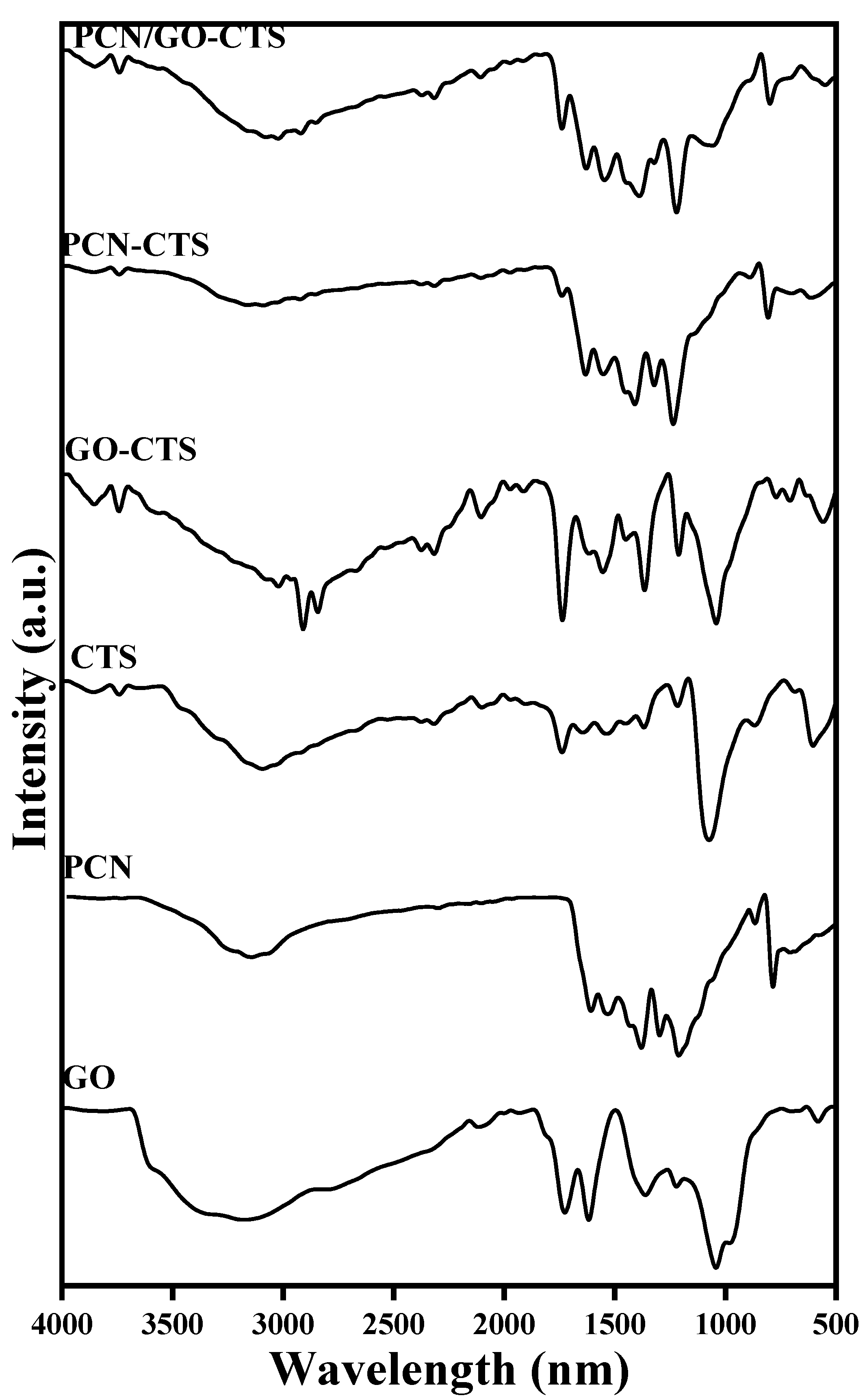
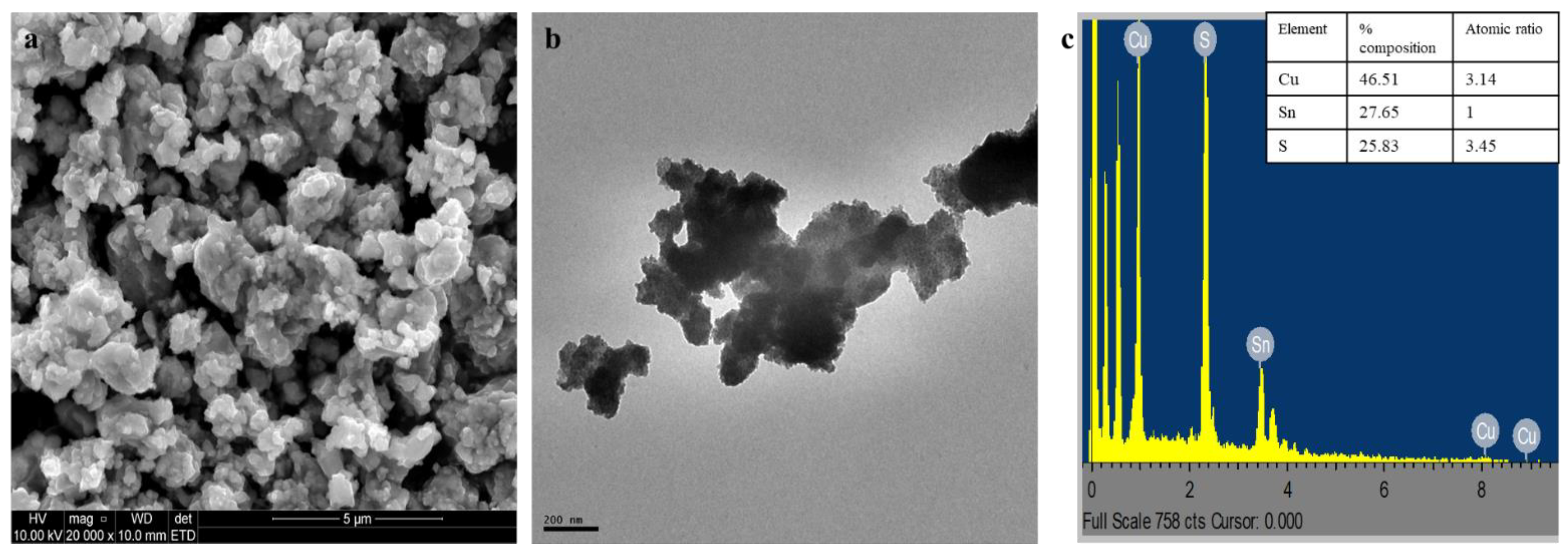
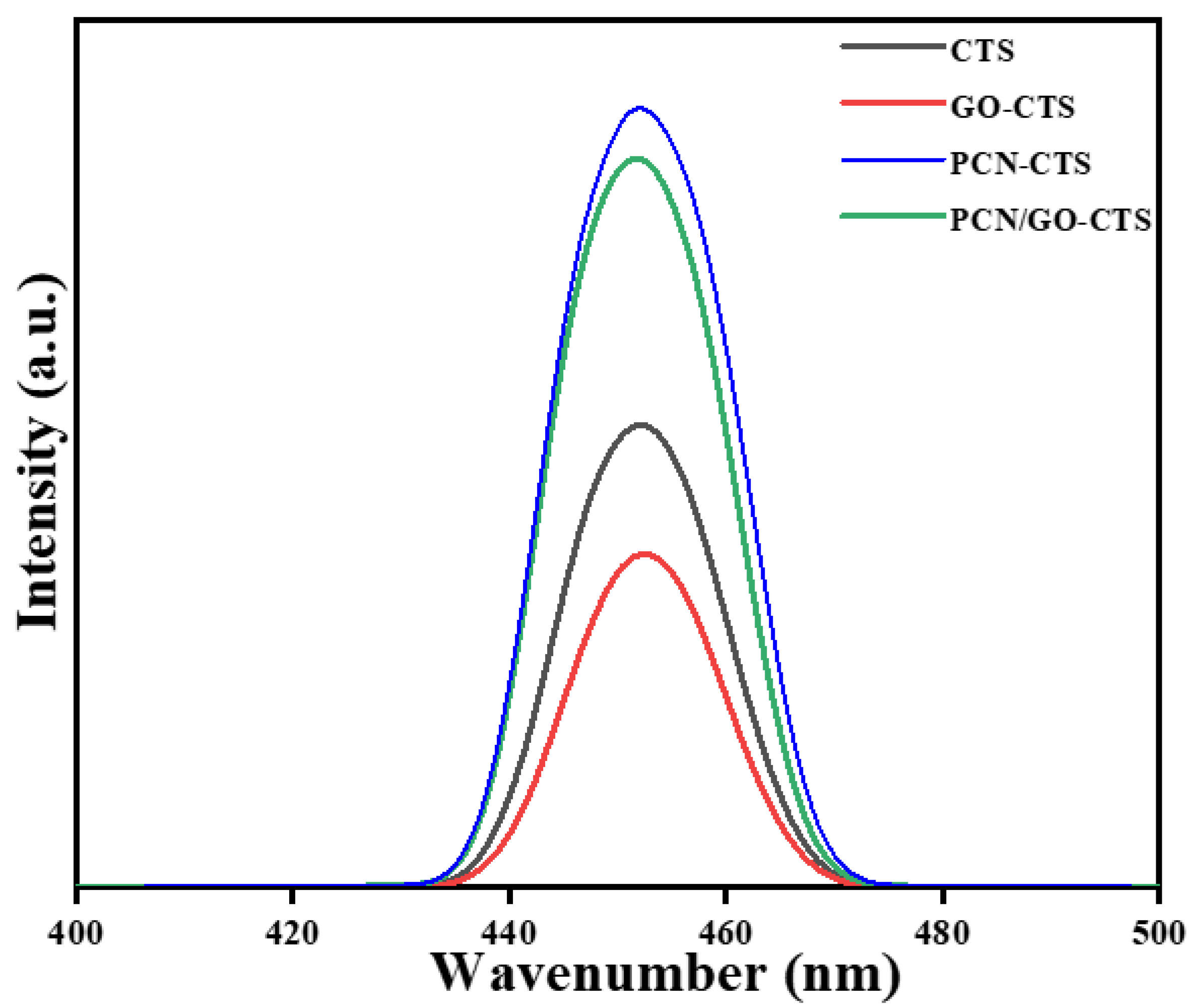
2.1. Characterization of GO, PCN, GO-CTS, PCN-CTS, and GO/PCN-CTS

The FTIR spectra of GO, PCN, GO-CTS, PCN-CTS, and GO/PCN-CTS are shown in Figure 1. The spectra of GO showed characteristic bands due to the vibrational frequencies of O-H, C-O, C=C, and C=O at 3248, 1220, 1720, 1620, and 1726 cm−1, respectively [32,33]. The characteristic bands due to N-H, C=N, C-N, and heterocyclic CN in PCN were observed at 3190, 1571, 1523, and 809 cm−1, respectively [34,35]. For the CTS nanoparticles, peaks from functional groups from DDT and OLA were observed in the spectra, thus confirming the presence of both ligands as capping agents for the nanoparticles. The stretching and bending vibrations of N-H in oleylamine were observed at ~3100 and 1620 cm−1, respectively, whereas its C-N stretching vibration was observed at ~1073 cm−1. The vibrational frequency band due to asymmetric and symmetric stretching of the methylene group of DDT overlapped with the N-H stretching band of oleylamine, and the twisting, rocking, and wagging vibrational frequency of the CH3 group could be seen at around 1600–1200 cm−1 [36]. Interestingly, the FTIR spectra of the composites revealed the possibility of a difference in the mode of interaction between CTS and the solid supports. The FTIR spectra of GO-CTS showed peaks that were characteristic of both CTS and GO. However, the asymmetric and symmetric stretching vibrations of DDT that were masked by the N-H peak of OLA became evident and the N-H peak shifted from around 3100 to 3000 cm−1. This suggests a significant interaction between the N-H group of OLA on the surface CTS and the O-H group on GO. The FTIR spectrum of the PCN-CTS composite showed only bands due to PCN. This observation has been reported by other related studies on GCN-based composite [37,38], and was attributed to the structure of GCN not being altered by compositing with semiconductor materials [39]. The suppression of the bands in pristine CTS may also suggest a strong interaction between the main functional groups on it and the PCN. In the spectrum of GO/PCN-CTS, the peaks due to both GO and PCN could be observed, with suppression of the peaks due to DDT and OLA. The O-H stretching vibration and the C-O stretching vibration of GO at 3200 and 1720 cm−1, respectively, could still be observed, and the C=N stretching frequency of PCN was still evident, thus confirming the incorporation of CTS onto the surface of both GO and PCN.
The XRD spectra of GO, PCN, CTS, GO-CTS, PCN-CTS, and PCN/GO-CTS are shown in Figure 2. The XRD pattern of CTS showed peaks that could be indexed to the orthorhombic phase of Cu3SnS4, with lattice parameters a = 6.52, b = 7.52, and c = 37.6Å and space group pmn 2i (JCPD No: 00-036-0217). The average crystallite size of the nanoparticles was calculated using Scherrer’s Equation (Equation (1)):
D = K λ β c o s θ
where D is the average crystallite size, K is the shape factor (0.90), λ is the X-ray wavelength, β is the line broadening at half the maximum intensity (FWHM) after subtracting instrumental broadening, and θ is the Bragg’s angle. The average crystallite size of the CTS was evaluated to be 15.3 nm. The XRD spectra of GO showed the characteristic peak arising from the stacking structure of GO at 2θ of 10.2, which corresponds to a d-spacing value of 0.863 nm. The PCN showed peaks that were typical of GCN [40]. The in-plane structural packing of the tri-s-triazine units with (001) diffraction was observed at 11.8°, whereas the peak at 27.70° was indexed as the (002) plane [41]. The indexes corresponded to a d-spacing value of 0.749 and 0.326 nm for the PCN layer. The broadness of the (002) diffraction plane was attributed to the interlayer stacking of conjugated aromatic systems in the graphitic carbon nitride.
There was a significant reduction in crystallinity in the XRD pattern of the composites, with PCN having the most influence on the crystallinity of CTS. Although the prominent peaks of CTS could still be observed in GO-CTS, albeit with a significant broadening of the peak around 28°, the CTS peaks were completely masked by the PCN peaks in PCN-CTS. This was also observed in the PCN/GO-CTS composite, which further confirms the strong interaction between PCN and CTS nanoparticles.
Figure 3 shows the SEM, TEM, and EDS spectra of CTS. SEM image of CTS revealed uniform, agglomerated spherical shaped nanocrystals, which was also supported by the TEM image. EDS spectra showed the presence of copper (Cu), tin (Sn), and sulfur (S) in the ratio of 3.14, 1, and 3.45 respectively, which is in agreement with the expected stoichiometric ratio. The SEM and TEM images of the composites showed that there was a significant difference in the level of agglomeration of CTS in the three composites. Figure S1 (in Supplementary Materials) shows the SEM, TEM, and EDS spectra and elemental mapping images of PCN-CTS. CTS nanoparticles on PCN were more agglomerated than the CTS deposited on GO, and the elemental mapping images showed the presence of Cu, Sn, S, C, and N, which confirms the incorporation of PCN and CTS. As shown in Figure S2, the SEM and TEM images of rGO-CTS revealed a lower level of aggregation of CTS particles when incorporated onto rGO. The elemental mapping images showed the presence of Cu, Sn, S, C, and O, confirming the incorporation of CTS and rGO and the uniform distribution of the nanoparticles onto support materials. For PCN/rGO CTS (Figure S3), significant improvement in the distribution of CTS on the composite was observed, showing a synergistic effect in the PCN/GO composite on the nanoparticle distribution. The elemental mapping images of PCN/GO-CTS showed the presence of Cu, Sn, S, C, N, and O, which confirms the presence of CTS, PCN, and GO in the composite.
The absorption spectra and the corresponding Tauc plots (insets) of PCN, GO, CTS, GO-CTS, PCN-CTS, and PCN/GO-CTS are shown in Figure 4a–f, respectively. The spectrum of PCN showed an absorption maximum edge at 302 nm, with the absorption tailing into the visible region. This tailing of the absorption may be attributed to the formation of band tail states, which has been reported to be due to the presence of N-defects in PCN [42]. The absorption spectrum of GO showed a very sharp absorption edge at about 303 nm, with the absorption falling almost immediately to zero. The calculated band gap for PCN and GO was 2.91 and 2.51 eV, respectively, which is in agreement with the values in the literature [42,43]. CTS showed two significant absorption bands at 312 and 418 nm, with the absorption intensity remaining significantly strong into the visible region. The three composites showed significant differences in their absorption spectra, indicating a difference in the influence exerted on the electronic structure of CTS by GO, PCN, and PCN/GO. In PCN-CTS, a blue shift of the band at 312 nm to 318 nm and broader bands were observed compared to pristine CTS. The absorption tails into the visible region were also reduced compared to CTS. For the GO-CTS, the absorption spectrum was also significantly influenced when compared to CTS. The absorption maximum was observed at 305 nm, which was closer to the value for GO and also very sharp. The absorption was also reduced significantly as it tailed into the visible region. The absorption spectra of PCN/CTS-GO showed a broad band at 305 nm, which could be attributed to GO. However, the absorption remained relatively strong into the visible region. A new absorption band was also observable at about 950 nm, and this could suggest the possible formation of new intra-band states in PCN/GO-CTS. The evaluated band gap for CTS, PCN-CTS, GO-CTS, and PCN/GO-CTS was 1.65, 1.46, 1.43, and 1.16 eV, respectively. Thus, a red shift to lower energy was observed by the incorporation of PCN and GO into CTS and the red shift was significantly enhanced by the incorporation of both PCN and GO.
To investigate the characteristics of photogenerated charge carrier recombination in the composites, emission spectra at an excitation wavelength of 450 nm were recorded using PL spectroscopy. Figure 5 shows the PL spectra of CTS, PCN-CTS, GO-CTS, and PCN/GO-CTS. Although no new photoluminescence phenomena were observed in the spectra of all the composites, the intensity of the PL bands was significantly altered. The GO-CTS exhibited a reduction in the band intensity relative to CTS, while the PL intensity was significantly increased in PCN-CTS. This suggests a difference in mechanism of charge carrier separation between the two composites. The charge carrier separation in GO-CTS can be attributed to the transfer of photogenerated electrons from the valence band of CTS to the π-π system of GO, with GO acting as an electron sink [44,45], whereas photogenerated electrons are possibly transferred to band-tail states in PCN-CTS [42,46]. These are the consequences of N-defects in PCN, as suggested by the absorption spectra. These defects in PCN are capable of trapping photogenerated electrons and increasing the probability of exciton occurrence, which accounts for the increase in the PL band [47]. Thus, PCN-CTS not only benefitted from the charge separation ability of PCN but also from the generation of excitons, which are important for the photocatalytic activity of the composite. In PCN/GO-CTS the PL intensity was also enhanced compared to CTS, but was slightly lower than PCN-CTS. The slight dip might be attributed to the quenching activity of GO. However, it could be observed that despite the equal composition of PCN and GO, the influence of PCN in the photogenerated charge carrier recombination was more significant.

2.2. Evaluation of Photocatalytic Activity

The photocatalytic activity of PCN, GO, CTS, PCN-CTS, GO-CTS, and PCN/GO-CTS was evaluated for the degradation of tetracycline under UV light irradiation. The degradation profile of TCE by the photocatalysts and kinetics plots for the degradation is shown in Figure 6. The degradation efficiency of CTS, PCN-CTS, GO-CTS, and PCN/CTS was 74.1, 85.2, 90.9, and 96.5%, respectively. Thus, both PCN and GO had a positive effect on the photocatalytic activity of CTS and the combination of PCN and GO resulted in a further enhancement of the degradation efficiency.
To understand the contribution of PCN and GO to the degradation activity of the composites, the degradation process was carried out using PCN and GO alone. As shown in Figure 6, no reduction in the concentration of TCE was observed during the adsorption–desorption equilibrium phase for PCN. However, upon irradiation with the light source, a degradation of approximately 5% was observed. This low degradation activity might have been a result of the limited adsorption of TCE to the PCN surface due to repulsion. It also suggests that the photogenerated charge carriers by PCN were not sufficient in effecting significant degradation. For GO, approximately 50% of the TCE was absorbed onto its surface during the adsorption–desorption equilibrium stage, and this may be attributed to the oxygen moieties on its surface. However, during the photocatalytic phase of the process, no significant reduction in the concentration of TCE was observed. This outcome was supported by the increase in adsorption experienced by the composites that contained GO. Although CTS exhibited high adsorptive property in the adsorption phase of the process, the incorporation of GO enhanced the adsorption activity of the composites compared to CTS. The adsorption activity of PCN-CTS was also significantly enhanced compared to CTS, and this may be attributed to the improvement of the surface area of PCN-CTS as a result of the lamellar and layered structure of PCN. The rate constants for the degradation were evaluated by a plot of −ln(Ct/Co) against time for each of the degradation processes (Figure 6). The rate constants for TCE degradation under UV light irradiation by CTS, PCN-CTS, GO-CTS, and PCN/GO-CTS were 1.45 × 10⁻², 2.57 × 10⁻², 4.43 × 10⁻², and 1.55 × 10⁻¹ min−1, respectively. This shows that the rate of degradation of TCE by CTS was enhanced by 1.77-, 3.05-, and 10.7-fold by the incorporation of PCN, GO, and PCN/GO, respectively.
The photocatalytic activity of CTS, PCN-GO, GO-CTS, and PCN/GO-CTS was compared using comparative parameters such as catalytic potential (CP%), electrical energy per order (EEO KW/h), and the time required for the process to achieve 90% degradation (t0.9). The values of CP, EEO, and t0.9 were evaluated using Equations (2)–(4).
CP(%) = Rcat − (R(UV-CTS) + R(UV-GO) + R(UV-PCN)),
E E O = P × 38.4 V × k
t 0.9 = 2.3035 k
where R(x) is the efficiency of a process, P is the power rating of light source, V is the column of the test solution, and k is the reaction rate constant. The values of the comparative parameters are shown in Table 1.

2.3. Proposed Mechanism for the Degradation Process

The adsorption of molecules onto the surface of a catalytic material and the generation of radical species are two important factors that significantly influence photocatalytic activity. The influence of adsorption on the photocatalytic activity of CTS and the composites were discussed in previous section. For the generation of radical species, the efficiency of charge carrier separation and the oxidizing-reducing ability of generated charge carriers are important in the efficiency of the degradation process. A plausible explanation of the charge carrier separation process was presented using the PL spectrum of the materials. In this section, the nature of radical species generated will be proposed by determining the band-edge values of the photocatalysts. The band states of the composites were evaluated using Equations (5) and (6) [48].
E C B =   Χ E e 0.5 E g  
E V B = E C B + E g
where Χ is the absolute electronegativity obtained from the geometric mean of the absolute electronegativity of the constituent element of the semiconductor, Eg is the band gap energy, and Ee is the energy of free electrons on the hydrogen scale. The value of X for CTS was determined to be 5.25 eV. The calculated ECB and EVB for the materials are presented in Table 2. This confirms that a significant alteration in the band state of CTS occurred by the incorporation of PCN and GO.
The band states of the materials support the earlier assertion that the degradation activity of the materials showed a difference in pathways due to the difference in their charge carrier recombination properties. The energy band states of the materials showed that the electrons generated in the conduction bands of the photocatalysts had smaller negative potentials than the O2/ O 2 (−0.33 eV) and, thus, are incapable of forming O 2 . The holes generated in the valence bands were also less positive than the OH/OH potential (1.99 eV), limiting the generation of OH [49]. However, the holes were capable of directly oxidizing organic molecules because of their high oxidizing power. Studies have shown that the higher the positive value of the EVB, the higher the oxidizing power of the photogenerated holes [47]. Therefore, the photocatalytic activity of CTS could be attributed to the photogenerated holes. The photocatalytic activity of GO-CTS could also have been due to the oxidizing ability of the photogenerated holes. Although the holes generated in GO-CTS were expected to have a lower oxidizing ability than the CTS, the large quantity of photogenerated holes due to the smaller band gap in GO-CTS compared to CTS and the improved adsorption of the pollutant could account for its improved activity [50]. Although the PCN-CTS possessed similar EVB as GO-CTS, its higher band gap implies that the quantity of photogenerated charge carriers was not as high as that obtained in GO-CTS, and this, coupled with its lower adsorption capacity, could account for its lower activity [51]. As suggested by the PL spectra, the occurrence of excitons could also be significant in the activity of PCN-CTS. In PCN/GO-CTS, the lower EVB suggests that the reducing ability of its holes was lower than that of the other photocatalysts, despite the tendency for a larger quantity of charge carriers being generated. However, the possible formation of excitons, as suggested by PL spectra, may account for the enhanced photocatalytic activity. The lower band gap of PCN/GO-CTS suggests that the intra band states, where electrons from the conduction band are transferred to, were closer to the valence band and enhanced the probability of exciton formation [52]. Excitons have been reported to enhance radical generation in photocatalysis by reacting with O2 via energy transfer to form singlet oxygen ( O 2   1 ) [53,54]. A schematic diagram of the proposed mechanism for PCN-CTS, GO-CTS, and PCN/GO-CTS composites is shown in Figure S5a–c.

3. Materials and Methods

3.1. Materials

The Cu(II) sulphate (CuSO4), diphenyl tin dichloride (R2SnCl2), carbon disulfide (CS2), dodecanethiol (DDT), oleylamine, urea, methanol, toluene, N-methyl aniline, graphite, potassium permanganate, nitric acid, sulfuric acid, ammonium hydroxide solution, and hydrochloric acid (HCl) used were all of analytical grade and used as supplied by Sigma-Aldrich (St. Louis, MO, United States).

3.2. Synthesis of Protonated Graphitic Carbon Nitride

The method described by Onga et al. [55] was employed for the synthesis of protonated g-C3N4. Firstly, 10 g of urea was weighed into a closed ceramic crucible with a lid in order to decrease the sublimation of the urea. The urea was then calcined at 550 °C in a furnace for 4 h. The crucible was allowed to cool to room temperature and the obtained yellow product was grounded into powder. The obtained bulk g-C3N4 was then exfoliated by treating it (1 g) with 40 mL of 32% HCl and ultrasound for 1 h. The obtained exfoliated g-C3N4 was then protonated by further stirring the g-C3N4-acid suspension vigorously for 4 h at room temperature. The mixture was filtered and washed repeatedly with deionized water to neutral pH. The obtained PCN was then dried at 50 °C for 24 h.

3.3. Synthesis of Graphene Oxide (GO)

The Tours method described by Marcano et al. [56] was employed in the synthesis of graphene oxide. In a typical synthesis, concentrated H2SO4 and H3PO4 were mixed in the ratio 9:1 and the solution was added to a mixture of graphite flakes and KMnO4 (graphite flakes/KMnO4 = 1/6). The mixture was then heated to 50 °C for 12 h with stirring. The thick greenish-purple paste obtained was allowed to cool to room temperature and then poured into 400 mL of ice. Hydrogen peroxide (30%) was added until the solution completely turned bright yellow. The obtained graphene oxide was then centrifuged and the residue obtained was washed three times with water, HCl, and ethanol. The obtained solid material was dried in an oven at 50 °C for 24 h and the sheet-like black GO obtained was grounded into powder and stored for further use.

3.4. Synthesis of Graphene Oxide/PCN Composites

GO/PCN composite was prepared through the method reported by Hu et al. [57]. GO dispersion (0.4 mg/L) was prepared by sonicating 20 mg of GO in water for 1 h. Afterwards, an equal amount of PCN was added to the GO dispersion. The mixture was further sonicated for another 1 h, then left to stir for 24 h and the solvent was allowed to evaporate by heating slowly at 70 °C. The obtained powder was washed thrice with ethanol and water and the GO/PCN powder was recovered after dispersing in ethanol and allowed to dry under vacuum overnight.

3.5. Synthesis of Cu3SnS4

Co-thermolysis of single-source precursors was used for the synthesis of Cu3SnS4. The precursors were initially prepared separately by reacting metal salts of copper (CuSO4) and tin (R2SnCl2) with dithiocarbamate ligands prepared via an earlier reported method [58]. Afterwards, the Cu3SnS4 (CTS) nanoparticles were prepared by mixing a stoichiometric amount of Cu(DTC)2 and Sn(DTC)2 in an oleylamine/DDT mixture with a volume ratio of 5:1 in a three-necked round-bottom flask attached to a condenser and an N2 gas source. The slurry obtained was then heated to 180 °C and maintained at that temperature for 1 h. Thereafter, the reaction system was allowed to cool down to 65 °C and the nanoparticles were precipitated with ethanol. The precipitated nanoparticles were washed with a mixture of ethanol and toluene (3:1) three times, after which they were air dried.

3.6. Characterization of Prepared Nanoparticles

The CTS nanoparticles and the nanocomposites were characterized for their structural, morphological, and optical properties. XRD patterns were recorded on a d8 Advanced XR diffractometer with Cu Kα radiation (λ = 154.18 pm) and operating in Bragg–Brentano mode. Morphological studies were carried out with scanning electron microscopy (SEM) and transmission electron microscopy (TEM) recorded on TECNAI G2 (ACI) equipment (Hillsboro, OR, USA) operating with an accelerating voltage of 200 kV. A PerkinElmer λ750s UV-vis spectrophotometer and PerkinElmer LS 45 fluorimeter were used to record the absorption and emission spectra of the samples, respectively.

3.7. Preparation of GO-CTS, PCN-CTS, and GO/PCN-CTS Composites

The facile ex situ mixing method was employed in the synthesis of the composites. In a typical synthesis of GO-CTS, CTS was dispersed in ethanol with sonication, while a weighted amount of GO (20% w/w) was simultaneously dispersed in water with sonication. After 1 h, the CTS mixture was transferred drop-wisely into the GO solution and the mixture was further sonicated for 1 h. The mixture was allowed to stir overnight and the solvent was slowly evaporated. Afterwards, the obtained powder was washed thrice with ethanol and water and then dried under vacuum. A similar process was followed in the synthesis of PCN-CTS and PCN/GO-CTS.

3.8. Evaluation of Photocatalytic Activity

The photocatalytic activity of CTS nanoparticles and composites was evaluated for the photocatalytic degradation of tetracycline (TCE) under UV-light irradiation. The process was carried out in a 100 mL glass beaker without controlling the pH of the system. In a typical process, 50 mL of 5 mg/L of TCE solution was stirred with 10 mg of the catalyst in the dark for 30 min in order to establish adsorption–desorption equilibrium. Afterwards, the 28 watt UV-LED light was turned on and aliquots were taken at intervals. The concentration of TCE in the system was measured using an ONDA UV spectrometer at a λmax of 360 nm. The percentage removal of TCE was evaluated using Equation (7):
%   r e m o v a l = C o C f C o × 100
where Co and Cf are the initial and final concentrations of TCE, respectively. The reaction rate for the degradation process was evaluated by fitting the degradation data into the linear form of the pseudo first-order kinetic (Equation (8)):
l n C f C o = K t
where Cf and Co are the final and initial concentration of TCE, respectively; K is the reaction rate constant; and t is the reaction time.

4. Conclusions

The effect of graphene oxide, graphitic carbon nitride, and a composite of both materials on the photocatalytic activity of copper tin sulfide (Cu3SnS4) was studied in this work. The morphological, structural, and optical properties of these composites were explored in explaining the factors contributing to the photocatalytic activity of these materials. Significant differences were observed in the absorption and emission spectra of the composites, indicating a notable interaction between the CTS and the support materials at the electronic state. Based on this study, a plausible mechanism was proposed for the degradation activity of the composites, which is suggested to be significantly due to the direct oxidative activity of the holes in CTS and GO-CTS, where the holes and excitons were probable charge carriers responsible for the activities of PCN-CTS and PCN/GO-CTS. This study therefore shows the possibility of altering the route of a photocatalytic process by changing the nature of the support material.

Supplementary Materials

The following supporting information can be downloaded at https://www.mdpi.com/article/10.3390/catal12010014/s1, Figure S1: (a) SEM, (b) TEM, (c) elemental mapping of carbon (C), (d) nitrogen (N), (e) sulfur (S), (f) Cu (copper), (g) tin (Sn), and (h) EDS spectra of PCN-CTS; Figure S2: (a) SEM, (b) TEM, (c) elemental mapping of carbon (C), (d) nitrogen (N), (e) sulfur (S), (f) Cu (copper), (g) tin (Sn), and (h) EDS spectra of GO-CTS; Figure S3: (a) SEM, (b) TEM, (c) elemental mapping of carbon (C), (d) nitrogen (N), (e) oxygen (O) (f) sulfur (S), (g) Cu (copper), (h) tin (Sn), and (i) EDS spectra of PCN/GO-CTS; Figure S4: Schematic diagram of the proposed mechanism of action of (a) GO-CTS (b) PCN-CTS, and (c) PCN/GO-CTS; Figure S5: Schematic diagram of the proposed mechanism for (a) PCN-CTS, (b) GO-CTS, and (c) PCN/GO-CTS composites.

Author Contributions

Methodology, formal analysis, investigation, writing—original draft, O.C.O.; Conceptualization, Supervision, funding acquisition, writing—review and editing, D.C.O.; All authors have read and agreed to the published version of the manuscript.

Funding

This research was funded by National Research Foundation (NRF), South Africa, Grant Number [UID109333 and UID 116,338]. The APC was funded by the North-West University, South Africa.

Institutional Review Board Statement

Not applicable.

Informed Consent Statement

Not applicable.

Data Availability Statement

Data is contained within the article or supplementary material.

Conflicts of Interest

The authors declare no conflict of interest.

References

  1. Olatunde, O.C.; Onwudiwe, D.C. Graphene-Based Composites as Catalysts for the Degradation of Pharmaceuticals. Int. J. Environ. Res. Public Health 2021, 18, 1529. [Google Scholar] [CrossRef] [PubMed]
  2. Su, D.S.; Zhang, J.; Frank, B.; Thomas, A.; Wang, X.; Paraknowitsch, J.; Schlogl, R. Metal-free heterogeneous catalysis for sustainable chemistry. ChemSusChem 2010, 3, 169–180. [Google Scholar] [CrossRef]
  3. Julkapli, N.M.; Bagheri, S. Graphene supported heterogeneous catalysts: An overview. Int. J. Hydrog. Energy 2015, 40, 948–979. [Google Scholar] [CrossRef]
  4. Heske, J.; Walczak, R.; Epping, J.D.; Youk, S.; Sahoo, S.K.; Antonietti, M.; Kühne, T.D.; Oschatz, M. When water becomes an integral part of carbon—Combining theory and experiment to understand the zeolite-like water adsorption properties of porous C2N materials. J. Mater. Chem. A 2021, 9, 22563–22572. [Google Scholar] [CrossRef]
  5. Cheng, Y.; Fan, Y.; Pei, Y.; Qiao, M. Graphene-supported metal/metal oxide nanohybrids: Synthesis and applications in heterogeneous catalysis. Catal. Sci. Technol. 2015, 5, 3903–3916. [Google Scholar] [CrossRef]
  6. Radsar, T.; Khalesi, H.; Ghods, V. Graphene properties and applications in nanoelectronic. Opt. Quantum Electron. 2021, 53, 178. [Google Scholar] [CrossRef]
  7. Papageorgiou, D.G.; Kinloch, I.A.; Young, R.J. Mechanical properties of graphene and graphene-based nanocomposites. Prog. Mater. Sci. 2017, 90, 75–127. [Google Scholar] [CrossRef]
  8. Soldano, C.; Mahmood, A.; Dujardin, E. Production, properties and potential of graphene. Carbon 2010, 48, 2127–2150. [Google Scholar] [CrossRef] [Green Version]
  9. Fan, X.; Jiao, G.; Zhao, W.; Jin, P.; Li, X. Magnetic Fe3O4–graphene composites as targeted drug nanocarriers for pH-activated release. Nanoscale 2013, 5, 1143–1152. [Google Scholar] [CrossRef]
  10. Pramanik, N.; Ranganathan, S.; Rao, S.; Suneet, K.; Jain, S.; Rangarajan, A.; Jhunjhunwala, S. A Composite of Hyaluronic Acid-Modified Graphene Oxide and Iron Oxide Nanoparticles for Targeted Drug Delivery and Magnetothermal Therapy. ACS Omega 2019, 4, 9284–9293. [Google Scholar] [CrossRef] [Green Version]
  11. Vinothkannan, M.; Kim, A.R.; Gnana Kumar, G.; Yoo, D.J. Sulfonated graphene oxide/Nafion composite membranes for high temperature and low humidity proton exchange membrane fuel cells. RSC Adv. 2018, 8, 7494–7508. [Google Scholar] [CrossRef] [Green Version]
  12. Xia, Z.; Wang, S.; Jiang, L.; Sun, H.; Qi, F.; Jin, J.; Sun, G. Rational design of a highly efficient Pt/graphene–Nafion® composite fuel cell electrode architecture. J. Mater. Chem. A 2015, 3, 1641–1648. [Google Scholar] [CrossRef]
  13. Dey, R.S. Development of Biosensors from Polymer Graphene Composites. In Graphene-Based Polymer Nanocomposites in Electronics; Sadasivuni, K.K., Ponnamma, D., Kim, J., Thomas, S., Eds.; Springer: Cham, Switzerland, 2015; pp. 277–305. [Google Scholar]
  14. Zhang, W.; Jia, B.; Furumai, H. Fabrication of graphene film composite electrochemical biosensor as a pre-screening algal toxin detection tool in the event of water contamination. Sci. Rep. 2018, 8, 10686. [Google Scholar] [CrossRef]
  15. Lu, Z.; Kong, Z.; Jing, L.; Wang, T.; Liu, X.; Fu, A.; Guo, P.; Guo, Y.-G.; Li, H. Porous SnO2/Graphene Composites as Anode Materials for Lithium-Ion Batteries: Morphology Control and Performance Improvement. Energy Fuels 2020, 34, 13126–13136. [Google Scholar] [CrossRef]
  16. Cong, R.; Choi, J.-Y.; Song, J.-B.; Jo, M.; Lee, H.; Lee, C.-S. Characteristics and electrochemical performances of silicon/carbon nanofiber/graphene composite films as anode materials for binder-free lithium-ion batteries. Sci. Rep. 2021, 11, 1283. [Google Scholar] [CrossRef] [PubMed]
  17. Tabish, T.A.; Memon, F.A.; Gomez, D.E.; Horsell, D.W.; Zhang, S. A facile synthesis of porous graphene for efficient water and wastewater treatment. Sci. Rep. 2018, 8, 1817. [Google Scholar] [CrossRef] [PubMed]
  18. Gandhi, M.R.; Vasudevan, S.; Shibayama, A.; Yamada, M. Graphene and Graphene-Based Composites: A Rising Star in Water Purification—A Comprehensive Overview. ChemistrySelect 2016, 1, 4358–4385. [Google Scholar] [CrossRef] [Green Version]
  19. Sachdeva, H. Recent advances in the catalytic applications of GO/rGO for green organic synthesis. Green Process. Synth. 2020, 9, 515–537. [Google Scholar] [CrossRef]
  20. Kong, X.-K.; Chen, C.-L.; Chen, Q.-W. Doped graphene for metal-free catalysis. Chem. Soc. Rev. 2014, 43, 2841–2857. [Google Scholar] [CrossRef] [PubMed]
  21. Georgakilas, V.; Otyepka, M.; Bourlinos, A.B.; Chandra, V.; Kim, N.; Kemp, K.C.; Hobza, P.; Zboril, R.; Kim, K.S. Functionalization of graphene: Covalent and non-covalent approaches, derivatives and applications. Chem. Rev. 2012, 112, 6156–6214. [Google Scholar] [CrossRef]
  22. Zhang, H. Molecularly imprinted nanoparticles for biomedical applications. Adv. Mater. 2020, 32, 1806328. [Google Scholar] [CrossRef]
  23. Wang, X.; Blechert, S.; Antonietti, M. Polymeric Graphitic Carbon Nitride for Heterogeneous Photocatalysis. ACS Catal. 2012, 2, 1596–1606. [Google Scholar] [CrossRef]
  24. Idris, M.B.; Devaraj, S. Few-layered mesoporous graphitic carbon nitride: A graphene analogue with high capacitance properties. New J. Chem. 2019, 43, 11626–11635. [Google Scholar] [CrossRef]
  25. Suter, T.; Brázdová, V.; McColl, K.; Miller, T.S.; Nagashima, H.; Salvadori, E.; Sella, A.; Howard, C.A.; Kay, C.W.M.; Corà, F.; et al. Synthesis, Structure and Electronic Properties of Graphitic Carbon Nitride Films. J. Phys. Chem. C 2018, 122, 25183–25194. [Google Scholar] [CrossRef] [Green Version]
  26. Shcherban, N.D.; Mäki-Arvela, P.; Aho, A.; Sergiienko, S.A.; Yaremov, P.S.; Eränen, K.; Murzin, D.Y. Melamine-derived graphitic carbon nitride as a new effective metal-free catalyst for Knoevenagel condensation of benzaldehyde with ethylcyanoacetate. Catal. Sci. Technol. 2018, 8, 2928–2937. [Google Scholar] [CrossRef]
  27. Sreekanth, T.V.M.; Basivi, P.K.; Nagajyothi, P.C.; Dillip, G.R.; Shim, J.; Ko, T.J.; Yoo, K. Determination of surface properties and Gutmann’s Lewis acidity-basicity parameters of thiourea and melamine polymerized graphitic carbon nitride sheets by inverse gas chromatography. J. Chromatogr. A 2018, 1580, 134–141. [Google Scholar] [CrossRef]
  28. Jin, X.; Balasubramanian, V.V.; Selvan, S.T.; Sawant, D.P.; Chari, M.A.; Lu, G.Q.; Vinu, A. Highly Ordered Mesoporous Carbon Nitride Nanoparticles with High Nitrogen Content: A Metal-Free Basic Catalyst. Angew. Chem. Int. Ed. 2009, 48, 7884–7887. [Google Scholar] [CrossRef] [PubMed]
  29. Humayun, M.; Ullah, H.; Usman, M.; Habibi-Yangjeh, A.; Tahir, A.A.; Wang, C.; Luo, W. Perovskite-type lanthanum ferrite based photocatalysts: Preparation, properties, and applications. J. Energy Chem. 2022, 66, 314–338. [Google Scholar] [CrossRef]
  30. Zhang, F.; Wang, X.; Liu, H.; Liu, C.; Wan, Y.; Long, Y.; Cai, Z. Recent Advances and Applications of Semiconductor Photocatalytic Technology. Appl. Sci. 2019, 9, 2489. [Google Scholar] [CrossRef] [Green Version]
  31. Daghrir, R.; Drogui, P. Tetracycline antibiotics in the environment: A review. Environ. Chem. Lett. 2013, 11, 209–227. [Google Scholar] [CrossRef]
  32. Khalili, D. Graphene oxide: A promising carbocatalyst for the regioselective thiocyanation of aromatic amines, phenols, anisols and enolizable ketones by hydrogen peroxide/KSCN in water. New J. Chem. 2016, 40, 2547–2553. [Google Scholar] [CrossRef]
  33. Ahmad, M.A.; Aslam, S.; Mustafa, F.; Arshad, U. Synergistic antibacterial activity of surfactant free Ag–GO nanocomposites. Sci. Rep. 2021, 11, 196. [Google Scholar] [CrossRef] [PubMed]
  34. Ben-Refael, A.; Benisti, I.; Paz, Y. Transient photoinduced phenomena in graphitic carbon nitride as measured at nanoseconds resolution by step-scan FTIR. Catal. Today 2020, 340, 97–105. [Google Scholar] [CrossRef]
  35. Zhu, G.X.; Lu, T.L.; Han, L.; Zhan, Y.Z. Graphitic carbon nitride (g-C3N4) as an efficient metal-free Fenton-like catalyst for degrading organic pollutants: The overlooked non-photocatalytic activity. Water Sci. Technol. 2020, 81, 518–528. [Google Scholar] [CrossRef]
  36. Jayabharathi, J.; Sundari, G.A.; Thanikachalam, V.; Jeeva, P.; Panimozhi, S. A dodecanethiol-functionalized Ag nanoparticle-modified ITO anode for efficient performance of organic light-emitting devices. RSC Adv. 2017, 7, 38923–38934. [Google Scholar] [CrossRef] [Green Version]
  37. Zhu, B.; Xia, P.; Li, Y.; Ho, W.; Yu, J. Fabrication and photocatalytic activity enhanced mechanism of direct Z-scheme g-C3N 4/Ag2 WO4 photocatalyst. Appl. Surf. Sci. 2017, 391, 175–183. [Google Scholar] [CrossRef]
  38. Zhang, W.; Zhou, L.; Deng, H. Ag modified g-C3N4 composites with enhanced visible-light photocatalytic activity for diclofenac degradation. J. Mol. Catal. A Chem. 2016, 423, 270–276. [Google Scholar] [CrossRef]
  39. Wang, H.; Li, X.; Ruan, Q.; Tang, J. Ru and RuOx decorated carbon nitride for efficient ammonia photosynthesis. Nanoscale 2020, 12, 12329–12335. [Google Scholar] [CrossRef]
  40. Sridharan, K.; Jang, E.; Park, J.H.; Kim, J.-H.; Lee, J.-H.; Park, T.J. Silver Quantum Cluster (Ag9)-Grafted Graphitic Carbon Nitride Nanosheets for Photocatalytic Hydrogen Generation and Dye Degradation. Chem. Eur. J. 2015, 21, 9126–9132. [Google Scholar] [CrossRef]
  41. Fina, F.; Callear, S.; Carins, G.; Irvine, J. Structural Investigation of Graphitic Carbon Nitride via XRD and Neutron Diffraction. Chem. Mater. 2015, 27, 2612–2618. [Google Scholar] [CrossRef] [Green Version]
  42. Xue, J.; Fujitsuka, M.; Majima, T. The role of nitrogen defects in graphitic carbon nitride for visible-light-driven hydrogen evolution. Phys. Chem. Chem. Phys. 2019, 21, 2318–2324. [Google Scholar] [CrossRef]
  43. Arranz-Mascarós, P.; Godino-Salido, M.L.; López-Garzón, R.; García-Gallarín, C.; Chamorro-Mena, I.; López-Garzón, F.J.; Fernández-García, E.; Gutiérrez-Valero, M.D. Non-covalent Functionalization of Graphene to Tune Its Band Gap and Stabilize Metal Nanoparticles on Its Surface. ACS Omega 2020, 5, 18849–18861. [Google Scholar] [CrossRef]
  44. Huang, J.; Fu, K.; Deng, X.; Yao, N.; Wei, M. Fabrication of TiO2 Nanosheet Aarrays/Graphene/Cu2O Composite Structure for Enhanced Photocatalytic Activities. Nanoscale Res. Lett. 2017, 12, 310. [Google Scholar] [CrossRef]
  45. Yeh, T.-F.; Cihlář, J.; Chang, C.-Y.; Cheng, C.; Teng, H. Roles of graphene oxide in photocatalytic water splitting. Mater. Today 2013, 16, 78–84. [Google Scholar] [CrossRef]
  46. Yu, X.; Ng, S.-F.; Putri, L.K.; Tan, L.-L.; Mohamed, A.R.; Ong, W.-J. Point-Defect Engineering: Leveraging Imperfections in Graphitic Carbon Nitride (g-C3N4) Photocatalysts toward Artificial Photosynthesis. Small 2021, 17, 2006851. [Google Scholar] [CrossRef]
  47. Liqiang, J.; Yichun, Q.; Baiqi, W.; Shudan, L.; Baojiang, J.; Libin, Y.; Wei, F.; Honggang, F.; Jiazhong, S. Review of photoluminescence performance of nano-sized semiconductor materials and its relationships with photocatalytic activity. Sol. Energy Mater. Sol. Cells 2006, 90, 1773–1787. [Google Scholar] [CrossRef]
  48. Wu, Q.; Zhou, M.; Gong, Y.; Li, Q.; Yang, M.; Yang, Q.; Zhang, Z. Three-dimensional bandgap-tuned Ag2S quantum dots/reduced graphene oxide composites with enhanced adsorption and photocatalysis under visible light. Catal. Sci. Technol. 2018, 8, 5225–5235. [Google Scholar] [CrossRef]
  49. Abdullah, E.A. Band edge positions as a key parameter to a systematic design of heterogeneous photocatalyst. Eur. J. Chem. 2019, 10, 82–94. [Google Scholar] [CrossRef]
  50. Ansari, S.A.; Cho, M.H. Highly Visible Light Responsive, Narrow Band gap TiO2 Nanoparticles Modified by Elemental Red Phosphorus for Photocatalysis and Photoelectrochemical Applications. Sci. Rep. 2016, 6, 25405. [Google Scholar] [CrossRef] [PubMed]
  51. Liu, W.; He, T.; Wang, Y.; Ning, G.; Xu, Z.; Chen, X.; Hu, X.; Wu, Y.; Zhao, Y. Synergistic adsorption-photocatalytic degradation effect and norfloxacin mechanism of ZnO/ZnS@BC under UV-light irradiation. Sci. Rep. 2020, 10, 11903. [Google Scholar] [CrossRef] [PubMed]
  52. Fischer, S.A.; Isborn, C.M.; Prezhdo, O.V. Excited states and optical absorption of small semiconducting clusters: Dopants, defects and charging. Chem. Sci. 2011, 2, 400–406. [Google Scholar] [CrossRef]
  53. Yang, F.; Chu, X.; Sun, J.; Zhang, Y.; Li, Z.; Liu, H.; Bai, L.; Qu, Y.; Jing, L. Efficient singlet oxygen generation by excitonic energy transfer on ultrathin g-C3N4 for selective photocatalytic oxidation of methyl-phenyl-sulfide with O2. Chin. Chem. Lett. 2020, 31, 2784–2788. [Google Scholar] [CrossRef]
  54. Wang, H.; Jiang, S.; Chen, S.; Li, D.; Zhang, X.; Shao, W.; Sun, X.; Xie, J.; Zhao, Z.; Zhang, Q.; et al. Enhanced Singlet Oxygen Generation in Oxidized Graphitic Carbon Nitride for Organic Synthesis. Adv. Mater. 2016, 28, 6940–6945. [Google Scholar] [CrossRef] [PubMed]
  55. Ong, W.-J.; Tana, L.-L.; Chaia, S.-P.; Yonga, S.-T.; Mohamed, A.R. Surface charge modification via protonation of graphitic carbon nitride (g-C3N4) for electrostatic self-assembly construction of 2D/2D reduced graphene oxide (rGO)/g-C3N4 nanostructures toward enhanced photocatalytic reduction of carbon dioxide to methane. Nano Energy 2015, 13, 757–770. [Google Scholar] [CrossRef]
  56. Marcano, D.C.; Kosynkin, D.V.; Berlin, J.M.; Sinitskii, A.; Sun, Z.; Slesarev, A.; Alemany, L.B.; Lu, W.; Tour, J.M. Improved Synthesis of Graphene Oxide. ACS Nano 2010, 4, 4806–4814. [Google Scholar] [CrossRef] [PubMed]
  57. Hu, S.; Zhang, W.; Bai, J.; Lu, G.; Zhang, L.; Wu, G. Construction of a 2D/2D g-C3N4/rGO hybrid heterojunction catalyst with outstanding charge separation ability and nitrogen photofixation performance via a surface protonation process. RSC Adv. 2016, 6, 25695–25702. [Google Scholar] [CrossRef]
  58. Onwudiwe, D.C.; Olatunde, O.C.; Mathur, S. Structural studies and morphological properties of antimony sulphide nanorods obtained by solvothermal synthesis. Phys. B Condens. Matter 2021, 605, 412691. [Google Scholar] [CrossRef]
Figure 1. FTIR spectra of GO, PCN, CTS, GO-CTS, PCN-CTS, and PCN/GO-CTS.
Catalysts 12 00014 g001
Figure 2. XRD spectra of GO, PCN, CTS, GO-CTS, PCN-CTS, and PCN/GO-CTS.
Catalysts 12 00014 g002
Figure 3. (a) SEM, (b) TEM, and (c) EDS images of CTS.
Catalysts 12 00014 g003
Figure 4. Absorption spectra of (a) PCN, (b) GO, (c) CTS, (d) GO-CTS, (e) PCN-CTS, and (f) PCN/GO-CTS and their respective Tauc plots (inset).
Catalysts 12 00014 g004
Figure 5. PL spectra of CTS, GO-CTS, PCN-CTS, and PCN/GO-CTS.
Catalysts 12 00014 g005
Figure 6. (a) Degradation profile of 5 mg/L of TCE using PCN, GO, CTS, GO−CTS, PCN−CTS, and PCN/GO−CTS, and (b) kinetics of degradation TCE by CTS, GO−CTS, PCN−CTS, and PCN/GO−CTS.
Catalysts 12 00014 g006
Table 1. Comparative parameters for the degradation of TCE by CTS, PCN−CTS, GO−CTS, and PCN/GO−CTS under UV light irradiation.
CP (%)EEO (KW/h)T0.9 (min)
CTS-22.1158.9
PCN−CTS6.112.489.6
GO−CTS15.97.252.0
PCN/GO−CTS22.42.114.9
Table 2. Energy band state values of CTS, PCN-CTS, GO-CTS, and PCN-CTS.
CTSPCN-CTSGO-CTSPCN/GO-CTS
ECB (eV)−0.0750.020.0350.17
EVB (eV)1.651.481.481.33
Publisher’s Note: MDPI stays neutral with regard to jurisdictional claims in published maps and institutional affiliations.

