Article

CO2-Induced Fibrous Zn Catalyst Promotes Electrochemical Reduction of CO2 to CO

1
Department of Catalysis Science and Technology and Tianjin Key Laboratory of Applied Catalysis Science & Technology, School of Chemical Engineering and Technology, Tianjin University, Tianjin 300350, China
2
Department of Materials Engineering, Xuzhou College of Industrial Technology, Xuzhou 221140, China
*
Authors to whom correspondence should be addressed.
Catalysts 2021, 11(4), 477; https://doi.org/10.3390/catal11040477
Submission received: 18 March 2021 / Revised: 3 April 2021 / Accepted: 5 April 2021 / Published: 8 April 2021

Abstract

:
The electrochemical reduction of CO2 is a promising strategy to achieve efficient conversion and utilization. In this paper, a series of Zn catalysts were prepared by electrodeposition in different atmospheric conditions (N2, CO2, H2, CO). A fibrous Zn catalyst (Zn-CO2) exhibits high electrochemical activity and stability. The Zn-CO2 catalyst shows 73.0% faradaic efficiency of CO at −1.2 V vs. RHE and the selectivity of CO almost did not change over 6 h in −1.2 V vs. RHE. The excellent selectivity and stability is attributed to the novel fibrous morphology, which increases the electrochemical active surface area. X-ray diffraction (XRD) results show that Zn-CO2 catalyst has a higher proportion of Zn (101) crystal planes, which is considered to be conducive to the production of CO. The search further demonstrates the importance of morphology control for the preparation of highly active and stable catalysts.

Graphical Abstract

1. Introduction

Over the past few years, heavy consumption of fossil fuels has increased the concentration of carbon dioxide (CO2) in the atmosphere, leading to many environmental problems such as greenhouse effect and energy dilemma [1]. It is widely accepted that reducing the concentration of CO2 is a key to solving environmental problems. The transformation and utilization of CO2 has become the focus of research for researchers. [2]. CO2 can be converted to high-value products such as carbon monoxide, methane, formic acid, methyl alcohol, ethyl alcohol, ethylene and so on [3,4,5,6,7,8], by electrochemical CO2 reduction reaction (CO2RR) under mild conditions. Therefore, electrochemical CO2RR is the most promising technology to achieve the conversion and utilization of CO2. The challenge of electrochemical CO2RR is the preparation of catalysts with high activity, selectivity and stability, which is the core for catalytic research.
Up to now, researchers have developed a number of catalysts for CO2RR. Noble metals such as Au [9,10,11,12,13] and Ag [14,15,16,17,18,19] are known to be the best metal catalysts for converting CO2 to CO with high activity and selectivity. However, it is difficult to use in large quantities in industrialization, due to the high price and scarce reserve of precious metals. Therefore, research into efficient non-noble metal catalysts has become an important part of the industrial application of electroreduction of CO2. Zn, an abundant metal, is proved to be an outstanding electrocatalyst to produce CO [20,21,22,23]. However, there are many challenges for the practical application of CO2 reduction. The reaction still suffers from poor stability and faradaic efficiency (FE) of the primary product. Therefore, the preparation of catalysts with high activity and selectivity is the core of future development.
There are many researchers who have studied Zn catalyst in recent years. In order to improve the performance of Zn catalysts for CO2RR, many strategies have been used in the preparation of catalysts, such as electrodeposition, anodization, oxide reduction [24]. Preparation of Zn catalyst with large surface area is considered as an effective method to enhance the activity of the catalyst. For example, electrodeposited Zn dendrite electrode has a surface area of around 90 cm2/cm2Geo, corresponding to over 80 times higher surface area than Zn bulk foil electrodes, and the FE of CO (FECO) is around 3-fold higher [25]. Recently, some researchers have studied the synthesis of catalysts in aqueous electrolyte with CO2-rich condition to improve the activity of catalysts. For example, Wang et al. synthesized Pb catalyst in an aqueous electrolyte with CO2-rich condition, and formic acid FE reached 90.5% [26]. Wang et al. reported Cu catalyst, which was synthesized under CO2 reduction conditions, with a 90% FE for C2+ [27]. This indicates that CO2 plays a key role in the preparation of highly active catalysts by electrodeposition.
In this work, a series of Zn catalysts were prepared by electrodeposition in different gas-saturated (N2, CO2, H2, CO) Zn(NO3)2 aqueous solutions. Linear sweep voltammetry (LSV), cyclic voltammetry (CV) and Tafel slope were employed to study the performances of different Zn catalysts for CO2RR. Zn-CO2 catalysts have the best activity and selectivity for electrochemical CO2RR. The Zn-CO2 electrode shows 73.0% faradaic efficiency of CO at −1.2 V vs. RHE. The partial current density of CO is 6.1 mA/cm2 and the selectivity of CO has almost not changed over 6 h in −1.2 V vs. RHE. X-ray diffraction (XRD), scanning electron microscopy (SEM), transmission electron microscopy (TEM) and X-ray photoelectron spectroscopy (XPS) characterization methods were used to investigate the relation of the structure and excellent activity of as-prepared catalysts in detail. XRD results show that Zn-CO2 catalyst has a higher proportion of Zn (101) crystal planes. The SEM images show that the surface of Zn-CO2 catalyst is covered by porous fibers with uniform tiny pores, which increases the electrochemical active surface area (ECSA). This is the main reason for the excellent catalytic performance of Zn-CO2 catalysts. The research prepared a Zn catalyst with new morphology and excellent activity and stability of electrochemical CO2RR, which develops a new means and idea for the preparation of more efficient and stable Zn catalysts. This work is of great value and significance in solving the challenge of low activity and poor stability in electrochemical CO2RR.

2. Results and Discussion

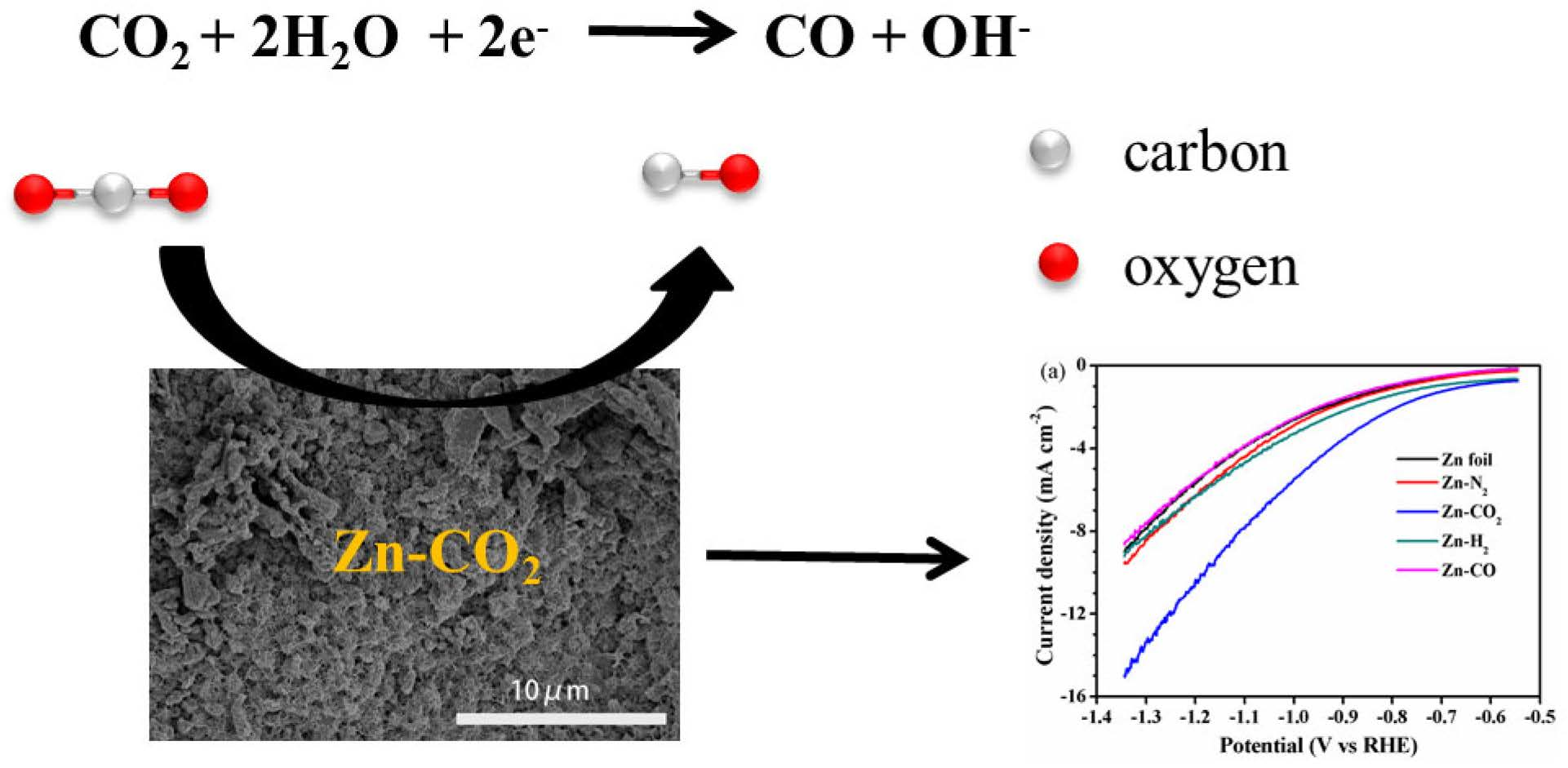
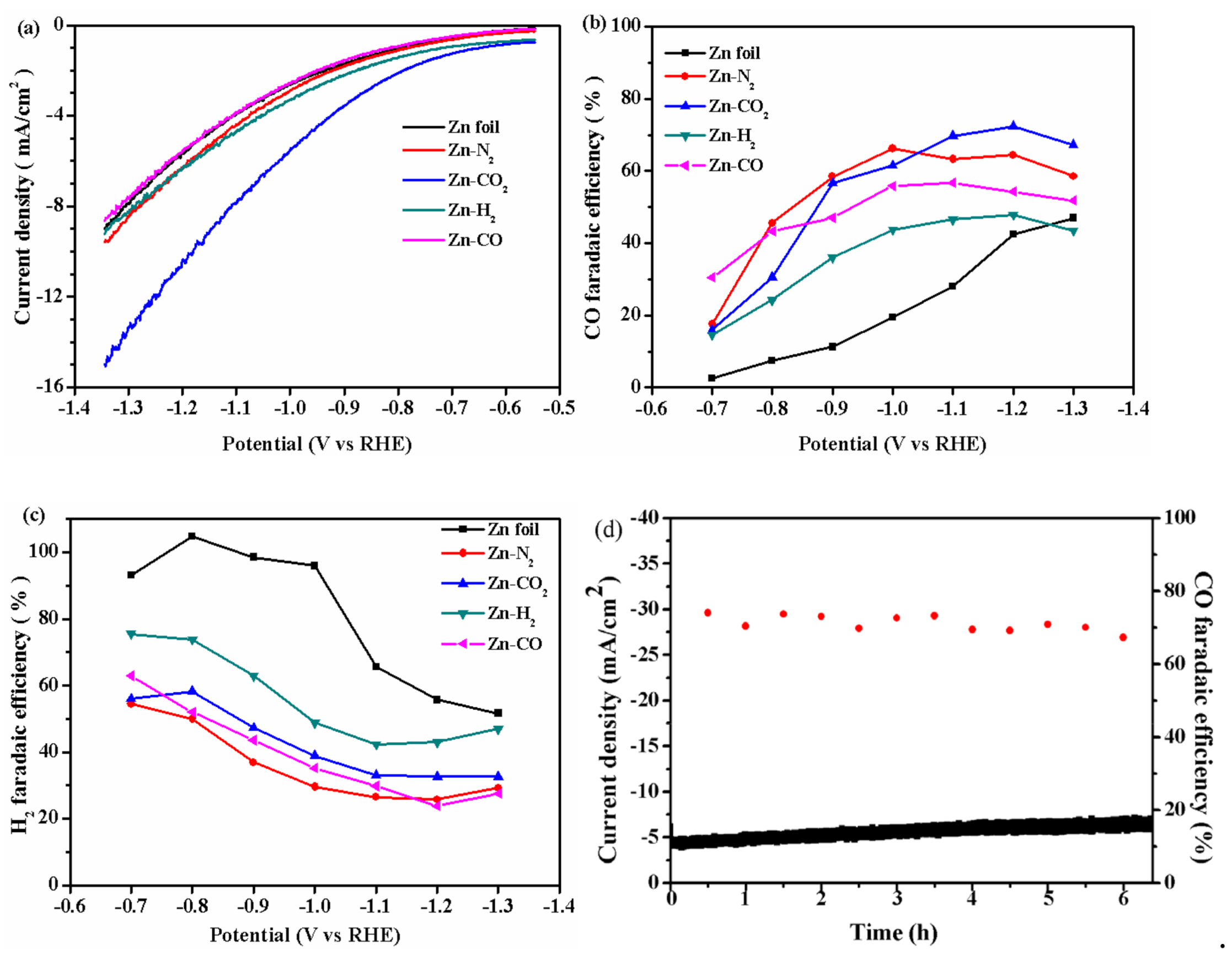
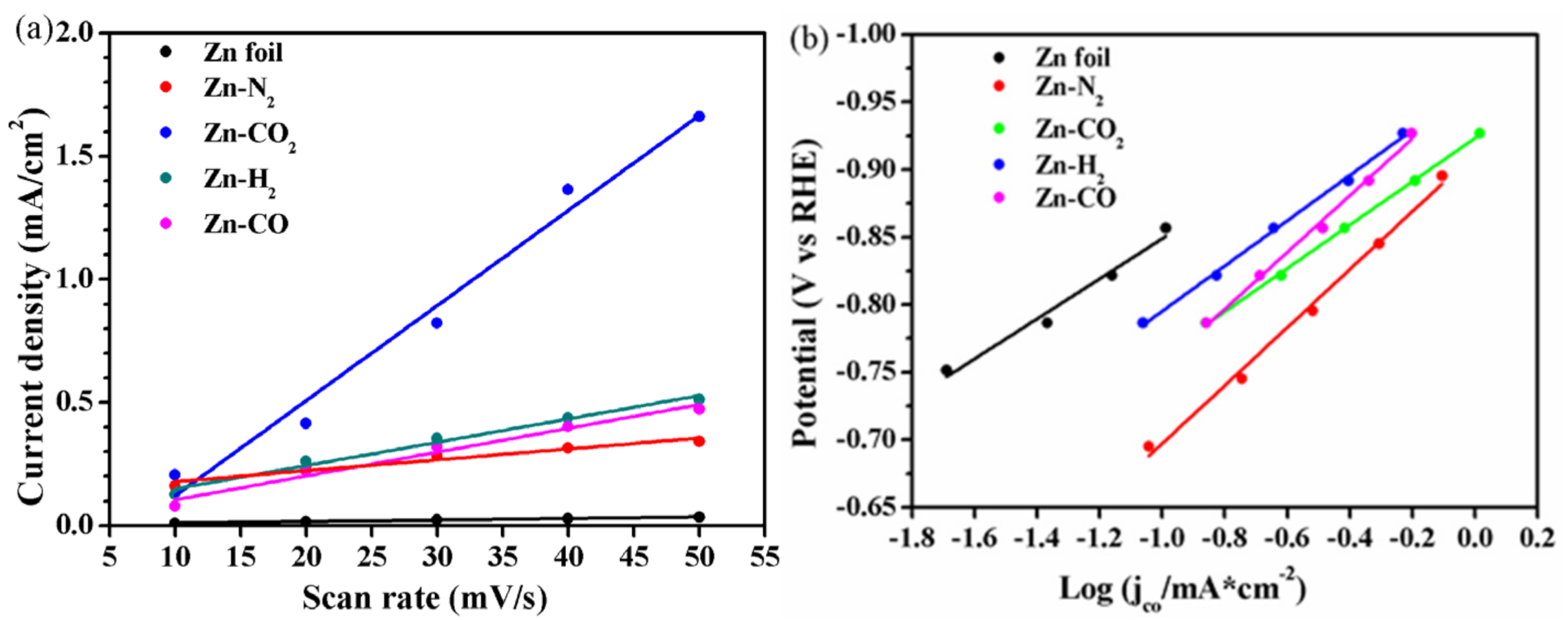
2.1. Electrochemical Performance

The electrochemical performance of the prepared electrodes for CO2RR was evaluated by linear sweep voltammetry (LSV) at 5 mV/s in pure KHCO3 electrolyte solution saturated with CO2. As shown in Figure 1a, the current density of the Zn-CO2 electrode is the highest and far higher than that of other electrodes, which indicates that the Zn-CO2 electrode has the best catalytic activity. To evaluate the electrochemical activity of Zn catalysts, the controlled potential electrolysis experiment was conducted at different cathodic potential to the CO2-saturated KHCO3 electrolyte. Before the controlled potential electrolysis experiment, cyclic voltammetry (CV) was performed over the potential range from −0.55 V vs. RHE to −1.35 V vs. RHE (50 mV/s) for 20 cycles to reduce the oxide layer of the catalyst. The main gas products which were detected every 30 min by gas chromatography (GC) were CO and H2. Figure 1b shows that the FECO for Zn foil electrode gradually increases with the decrease of applied voltage, and reaches a maximum of 47.0% at −1.3 V. Zn-N2 electrode has a FECO at 66.2% at −1.0 V vs. RHE, and decreases gradually with the decrease of applied voltage which indicates that the H2 evolution reaction (HER) is more serious at more negative voltage for Zn-N2 electrode. This can also be demonstrated by the diagram of the FE of H2 as a function of voltage (Figure 1c), which FEH2 increases gradually when the voltage exceeds −1.2 V vs. RHE. The maximal FECO is found on Zn-CO2 electrode with 73.0% at −1.2 V vs. RHE (Figure 1b), and with the lowest FEH2 of 32.6% (Figure 1c), and the partial current density of CO is 6.1 mA/cm2 at −1.2 V vs. RHE (see Table S1). This indicates the production of CO is promoted and the production of H2 is inhibited at −1.2 V. The Zn-H2 electrode has a FECO of 47.9% at −1.2 V vs. RHE, and the Zn-CO electrode has a FECO at 56.7% at −1.1 V vs. RHE. These results show that the catalyst prepared by electrodeposition in CO2-saturated Zn(NO3)2 aqueous solution can effectively promote the production of CO. To evaluate the long-term performance of the Zn-CO2 electrode, a chronoamperometry experiment at −1.2 V vs. RHE was carried out. As shown in Figure 1d, the current density is stable at 4.6 mA/cm2, and the FECO remains unchanged (~73.0%) over 6 h. The stability evaluations of other electrodes under the same conditions were also carried out, and the results are shown in Figure S1. The FECO for Zn foil and Zn-H2 electrode decreased gradually with the increase of time during 6 h, while their current density is still stable. The current density for the Zn-N2 electrode maintains stable before 5 h and then decreases dramatically after reaction of 5 h, at the same time, the FECO fluctuates between 40.0% and 60.0%. A similar phenomenon appears in the Zn-H2 electrode. This shows the Zn foil, Zn-N2, Zn-H2 and Zn-CO electrodes have very poor stability. According to these comparative experimental results, the Zn-CO2 electrode exhibits excellent stability.

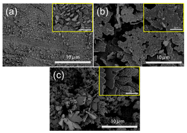
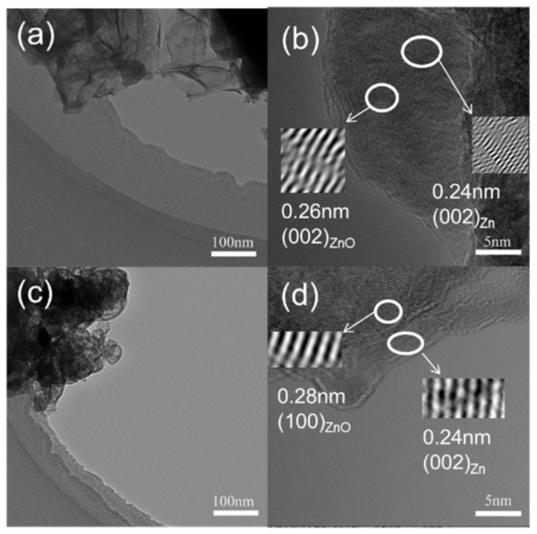
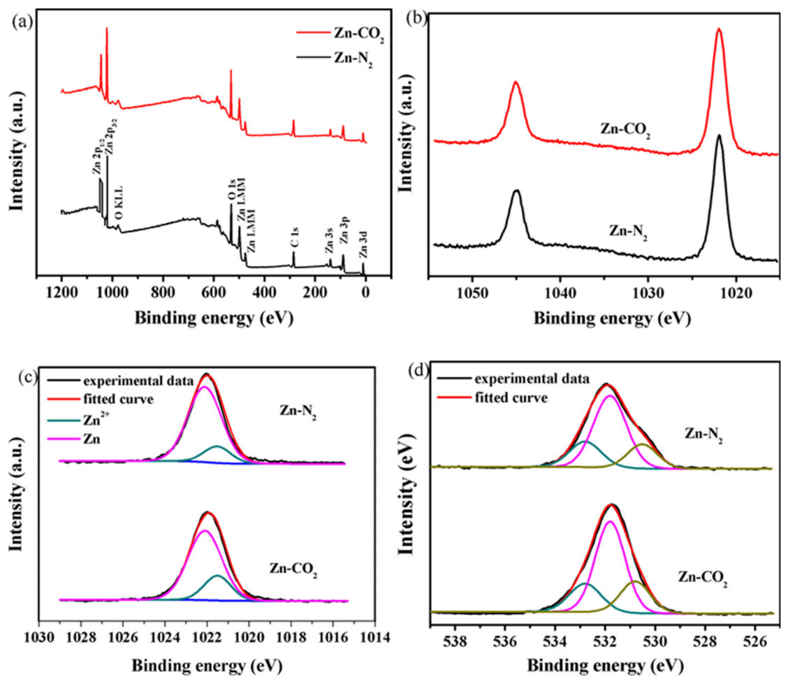
2.2. Characterization of Catalysts

A lot of characterizations were performed to analyze the physical and chemical properties of the catalysts. First of all, XRD was measured to analyze the crystal structure of electrodeposited Zn. Figure 2a exhibits the XRD patterns of all prepared Zn electrodes and Zn foil electrode. It shows that there appear peaks at 36.3°, 39.0°, 43.2°, 54.3°, 70.1°, 70.6°, and 77.0° corresponding to (002), (100), (101), (102), (103), (110) and (004) lattice planes of metallic Zn [JCPDS file No. 04-0831], respectively [28] indicating that Zn catalysts with high crystallinity can be prepared by electrodeposition in different gas-saturated Zn(NO3)2 aqueous solutions. In order to research the influence of different atmospheres for electrodeposited Zn catalysts, the texture coefficient of each crystal face for the Zn catalysts is calculated and dotted in Figure 2d. The texture coefficients of the Zn (101) plane are 16.79%, 19.16%, 20.79%, 20.6%, 17.59% corresponding to Zn foil, Zn-N2, Zn-CO2, Zn-H2, Zn-CO electrode, respectively, which are consistent with the trend of corresponding current densities. The Zn-CO2 electrode has the highest Zn (101) plane ratio while Zn foil has the minimum Zn (101) plane ratio. This is due to the strong binding ability of intermediates formed during Zn(NO3)2 electroreduction in CO2-saturated aqueous solutions, which promotes the specific growth of Zn crystals on electrode [26]. As reported in literature [29,30], the Zn (101) plane is conducive to the CO2RR to CO. On the other hand, the Zn (002) plane is responsible for H2 evolution in electrochemical CO2RR [29,30]. The texture coefficients of the Zn (002) plane are 16.00%, 13.16%, 10.51%, 11.27%, 11.85% corresponding to Zn foil, Zn-N2, Zn-CO2, Zn-H2, Zn-CO electrode, respectively. The Zn-CO2 electrode has a small Zn (002) plane ratio while the Zn foil electrode has the biggest Zn (002) plane ratio. The different proportion of crystal face of Zn catalysts may promote the formation of different morphologies. The greater proportion of Zn (101) promotes the generation of CO on Zn-CO2 electrode.
The XRD patterns of used catalysts and reduced Zn-CO2 electrode were also given. As shown in Figure 2b, the XRD patterns of used catalysts are the same as the corresponding fresh catalysts, and there are no any new phases appearing in these catalysts. In the reduced Zn-CO2 electrode, the XRD pattern also exhibits the characteristic reflections of a single crystalline Zn phase. This indicates that catalyst has been reduced by electrochemical reduction methods.
The surface morphology of representative Zn electrodes was characterized by a scanning electron microscope (SEM) and shown in Figure 3. Obviously, each electrode surface is coarse and porous. On the surface of the Zn-N2 and Zn-CO electrode, the pore channels with various sizes are found to be partially covered by non-porous sheets. For the Zn-H2 electrode, these non-porous sheets covered on the surface of the hierarchical pores fully disappear and are replaced by abundant tiny pores. In particular, the surface of the Zn-CO2 electrode is covered by porous fibers with uniform tiny pores. The different surface morphology should be due to different gas dissolving capacity in Zn(NO3)2 solution and interaction among gas, Zn(NO3)2 and Zn foil. The special morphology of the Zn-CO2 electrode is just due to the higher solubility of CO2 in aqueous solution (see Table S2) and a stronger interaction between CO2 and Zn interface than those of other gases resulting in the stable and uniform growth of Zn crystal during the whole electrodeposition process. Correspondingly, the heterogeneous surface morphology for other electrodes should be related to the low solubility and quick escape of gases from the solution. The surface morphology plays an important role in the CO2RR on a three-phase interface. According to the relative high current density of CO2 conversion on the Zn-CO2 electrode shown in Figure 1a, it can be confirmed that the uniform and abundant tiny pores on the Zn-CO2 electrode may be more beneficial for CO2 enrichment by enhancing surface area than other electrodes with low surface area resulting from the bigger pore channels and even non-porous surface. As for the CO and H2 selectivity, it should be the result of the combined effects, including the pore diffusion and surface enrichment of CO2 and H2O molecules, under efficient three-phase contact of CO2 gas, liquid H2O and solid catalyst [31]. The high FECO for the Zn-CO2 electrode should be attributed to the special surface morphology, which can increase surface area to accommodate high concentrations of CO2 and the uniform tiny pores on porous fibers are beneficial to CO2 permeation and detrimental to H2O molecular diffusion. Instead, the appearance of big pores and non-porous sheets means the shrinkage of surface area, which results in the decrease of surface concentrations of CO2 and H2O, but is conducive to the H2O molecular diffusion, resulting in the possible increase of FEH2 and decrease of FECO in a certain degree. Certainly, the catalytic performance should be determined by the competition between two reactions of CO2RR to CO and HER (also known as electrochemical water reduction to H2), which depends on the concentration and diffusion ability of CO2 and H2O molecules.
In addition, we compared the morphology of the catalyst after the reaction (Figure 4) and found that the Zn foil, Zn-N2 and Zn-CO2 catalysts accumulated into a regular nanosheet structure. The nanosheet of the Zn-N2 electrode is much larger in size than other electrodes after reaction, and more irregular than other electrodes. It is the reason that current density is higher in the initial stage and more unstable. The nanosheet greatly reduced the ECSA of the catalysts, which was one of the reasons for the catalyst’s death, after 6 h of reaction.
Furthermore, the representative Zn-N2 and Zn-CO2 electrodes were also analyzed by transmission electron microscope (TEM) and the TEM images for these representative samples are shown in Figure 5. The nanosheets can be found easily on each sample, which constructs the skeleton of pore channels. Obviously, the size of nanosheets on the Zn-CO2 electrode is uniform and far less than that on the Zn-N2 electrode. The results are consistent with those of SEM. In addition, the existence of the Zn (002) plane can further be demonstrated by the lattice spacing of 0.24 nm of two electrodes. Besides the metal Zn phase, the characteristic spacing of 0.26 nm for ZnO (002) for the Zn-N2 electrode, and 0.28 nm for the ZnO (100) lattice plane for the Zn-CO2 electrode can be seen. The results also confirm that ZnO can be formed during the preparation process, indicating the importance of electrochemical reduction of the electrode prior to the reaction.
X-ray photoelectron spectroscopy (XPS) was performed to demonstrate the chemical states of Zn and O elements on the surface of the catalysts. The XPS spectra are given in Figure 6 and the characteristics data are collected in Table 1. According to the XPS survey scan as shown in Figure 6a, it can be further confirmed that Zn and O elements exist on the Zn-N2 and Zn-CO2 electrodes. As for the XPS spectra of Zn 2P region, there are two deconvoluted peaks (Figure 6b). The peak at 1021.8 eV is associated with Zn 2P3/2. Figure 6c shows the Zn 2P3/2 spectrum of Zn-N2 and Zn-CO2 electrode. It shows Zn in two states, 1021.5 eV and 1022.1 eV, respectively. The low binding energy (BE) peak can be assigned to the metallic Zn (Zn0), while the high BE peak should be ascribed to the oxidized Zn (Zn2+). The ratio of Zn2+/total of Zn-CO2 electrode is higher than that of the Zn-N2 electrode, it is due to the fibrous structure and pore diameter resulting in the formation of more under-coordinated Zn2+ species on the surface of small particles, especially at the tip of pore mouths [25]. Before the reaction, the reduction treatment can transfer the under-coordinated Zn2+ species into active Zn species. These oxidized Zn sites may facilitate the adsorption of reactants and *COOH intermediates on the surface of the Zn electrode, thus improving the generation of CO in the reaction [32]. Moreover, three fitted peaks can be seen in the O 1s regions. The peak at 530.6 eV is associated with O2- from ZnO. The peak at 531.8 eV is related to hydroxyl group on the surface [33] and the peak at 532.8 eV is attributed to adsorbed oxygen. The adsorbed oxygen comes from oxygen in the absorbed water molecules [32,34]. The proportion of O 1s peak at 530.6 eV, associated with ZnO in the Zn-CO2 electrode, is higher than the Zn-N2 electrode. It indicated that the presence of CO2 will promote the formation of under-coordinated Zn2+ species on the surface of the Zn electrode in the process of electrodeposition. The under-coordinated Zn2+ may facilitates the adsorption of *COOH intermediates on the surface of the Zn electrode and enhances the ability of intermediate to bind with the Zn electrode [35]. But this is not the significant distraction factor for catalytic excellent performance of Zn-CO2. It is because Zn-N2 and Zn-CO2 electrodes have the under-coordinated Zn2+ and the difference between them is not particularly great.
In order to explore the reasons for the superior CO2RR performance of Zn-CO2 electrode, it is necessary to compare the ECSA of each electrode by measuring their specific double-layer capacitance calculated by a CV scan in Figure S2. The result is shown in Figure S2, and the data of specific double-layer capacitance were calculated from this result. The line regression of the double layer capacitance and Tafel plot are displayed in Figure 7 and the corresponding ECSA and Tafel slope data of all samples are summarized in Table 2. The results show that the Zn-CO2 electrode has the largest ECSA value (19.295 mF/cm2) which is 60 times that of the Zn foil electrode (0.309 mF/cm2), and the other electrodes, Zn-N2, Zn-H2 and Zn-CO, give a lower ECSA value (from 2.210 to 4.835 mF/cm2). The quite high ECSA for Zn-CO2 electrode is related to the special porous fibers with uniform tiny pores, which can enhance the surface concentration and diffusion ability of CO2. In general, during electrodeposition, the presence of CO2 affects the growth of crystal surfaces and promotes the formation of porous fibers morphology, which leads to a larger ECSA. This is the main reason for excellent performance of electrochemical CO2RR for the Zn-CO2 electrode.
To elucidate the origin of the remarkable CO2RR performance over our catalysts, we performed detailed electrokinetic studies to compare the CO2 reduction pathway on all electrodes by comparing the experimentally observed Tafel slope (logarithm of the partial current density towards a specific product vs. potential). There are four elementary reaction steps for CO2RR to CO:
*CO2 + e → *CO2
*CO2 + H+ → *COOH
*COOH + H+ + e → *CO + H2O (l)
*CO → CO + *
where * represents an active site. Firstly, the absorbed CO2 gains an electron to form to *CO2 anion radical. Secondly, the *CO2 anion radical binds with a proton to form the *COOH intermediate. Thirdly, the *COOH intermediate gains a proton and an electron and is reduced *CO intermediated and H2O. Finally, the *CO is desorbed from the surface of catalysts to form CO. It is well known that the value of a Tafel slope can reflect the rate-control steps of the reaction under certain conditions. Figure 7b shows that Zn-CO2 electrode and Zn foil have Tafel slope of 229.34 mV/dec and 211.7 mV/dec, respectively. These are close to the theoretical value of 250 mV/dec for a rate limiting step at higher overpotential (−0.6 to −0.7 V) [24,36]. The higher value implies that the initial electron transfer step is the rate-determining step (RDS) [28]. The Zn-H2 and Zn-CO electrodes have higher Tafel slope of 239.54 mV/dec and 253.28 mV/dec. From these data, it can be inferred that the RDS of electrochemical reduction reaction is mainly the first step of electron transfer step on these Zn electrodes. This indicated the *CO2 intermediate plays a crucial role in the CO2RR reaction. The same RDS indicated that the CO2RR reaction may have similar intrinsic activity on these Zn catalysts [24].

3. Experimental Section

3.1. Fabrication of Zn Catalysts

Zn foil electrodes (1 cm × 2 cm) were prepared by mechanical polishing using sandpaper (800 grit), followed by sonication in acetone, ethanol and deionized water for 30 min. Zn(NO3)2 (Tianjin Fengchen Chemical Regents Factory, Tianjin, China)aqueous solution (30 mL, 0.05 M) was purged with different gases (N2, CO2, H2, CO) as a precursor solution. A chronoamperometry experiment setting at −1.85 V vs. SCE (300 s) was used to reduce Zn precursor to metallic Zn on the surface of the prepared Zn foil electrode. After deposition, the electrode was rinsed by deionized water and then immediately taken for electrochemical testing to prevent electrode oxidation again.

3.2. Eelectrocatalytic Test for CO2RR

An electrochemical workstation (CHI instrument 660E, Chenhua, Shanghai, China) was used for all electrochemical tests. The electrochemical measurements were performed in a three-electrode system. The reference electrode was a saturated calomel electrode (SCE) and the counter electrode was a Pt sheet, respectively. All potentials in this work are quoted versus the reversible hydrogen electrode (RHE), according to the Nernst equation of:
E R H E = E S C E + 0.0591 P H + 0.241
CO2RR was conducted in a gas-tight two component H-type electrochemical cell separated by Nafion 117 cation-exchange membrane (Dupont, Wilmington, DE, USA). 0.1 M KHCO3 (99.5%) aqueous solution was used as electrolyte and was purged with CO2 (99.999%) at a rate of 20 mL/min for at least 30 min before the testing of CO2RR. During the testing, the electrolyte was stirred by a magnetic stirring apparatus. The gas phase products were detected by a gas chromatograph (GC, SP2100) which was equipped with a TDX-01 column. A flame ionization detector (FID) was equipped with methanizer to analyze CO and a thermal conductivity detector (TCD) to analyze H2. The FE of product was calculated by Equation (6).
FE % = z n F Q × 100 %
where z is 2 for CO2RR to CO or H2, n is the mole number of the products, Faraday’s constant F is 96,485 C/mol, and Q is the total charge passed.

3.3. Catalyst Characterization

XRD tests were performed on a D8-Foucas (BRUKER AXS GMBH, Karlsruhe, Germany) equipped with a Cu Kα radiation (λ = 0.15418 nm). The spectra were collected between 2θ ranges of 30–80°, at a scanning speed of 8°/min.
To compare the crystal facet ratio of different Zn catalysts, texture coefficients [29] were calculated by Equation (7).
T C h k l = I ( h k l ) / I 0 ( h k l ) n i = 1 I ( h k l ) / I 0 ( h k l ) × 100 %
where I(hkl) is the diffraction intensity of the (hkl) facet and is automatically calculated by the Jade software, I0(hkl) is the standard diffraction intensity of the (hkl) and taken from JCPDS#04-0831, and n is the number of diffraction peaks of Zn (n = 7).
The TEM images of Zn catalysts were tested by a JEM2100-F field-emission transmission electron microscope (JEOL, Tokyo, Japan). The field SEM images of Zn catalysts were tested by a Regulus 8100 instrument (JEOL, Tokyo, Japan) at a 3.0 KV electron beam. The surface chemical states of the Zn electrode were investigated by XPS (ULVACPHI, Japan) with monochromatized Al Kα X-ray radiation (1486.6 eV).

4. Conclusions

In summary, a series of Zn catalysts were prepared by electrodeposition in different gas conditions (N2, CO2, H2, CO). The Zn-CO2 catalyst obtained with porous fibers and uniform tiny pores exhibited high activity and selectivity for CO2RR to CO, with FECO for 73.0% and FEH2 for 32.6% at −1.2 V vs. RHE. The partial current density of CO was 6.14 mA/cm2 and the FECO was almost unchanged over 6 h in −1.2 V vs. RHE. The electrokinetic study results show that the initial electron transfer step was the RDS for the Zn-CO2 electrode. The presence of CO2 affected the crystal growth of electrodeposited Zn, increased the proportion of the Zn (101) crystal on the Zn electrode surface, and induced the formation of a fibrous and porous structure. The structure increased the ECSA and under-coordinated Zn2+ species. The greater ECSA provided more active sites and promoted the production of CO. This was the main reason for the excellent performance of electrochemical CO2RR for the Zn-CO2 electrode. This study demonstrates that the morphology and crystal structure of Zn catalysts have a great influence on the activity for CO2RR. This work is of great value and significance to solve the challenge of low activity and poor stability in electrochemical CO2RR.

Supplementary Materials

The following are available online at https://www.mdpi.com/article/10.3390/catal11040477/s1, Figure S1: Current density and FECO for (a) Zn foil, (b) Zn-N2, (c) Zn-H2 and (d) Zn-CO electrodes during 6 h of long-time operation at −1.2 V vs. RHE; Figure S2: CV curves on (a) Zn foil, (b) Zn-N2, (c) Zn-CO2, (d) Zn-H2 and (e) Zn-CO electrodes with a potential range from −0.415 to −0.515 V vs. RHE in a N2 bubbled 1 M Na2SO4 electrolyte; Table S1: The data of CO partial current density for Zn-CO2 electrode; Table S2: The solubility data of different gases in water.

Author Contributions

M.G. wrote the manuscript, performed the experiments and analyzed data; M.G., X.L. and Y.H. collected references and characterized the physic-chemical properties of materials; L.L. and J.L. collected and checked data; Y.X. and Y.L. analyzed data and checked the manuscript; L.Z. provided research ideas, analyzed data and revised the manuscript. All authors have read and agreed to the published version of the manuscript.

Funding

This research was funded by National Natural Science Foundation of China (21776214) and Natural Science Foundation of Jiangsu Province (BK20161166).

Data Availability Statement

Data is contained within the article or Supplementary.

Conflicts of Interest

The authors declare no conflict of interest.

References

  1. Zheng, T.; Jiang, K.; Ta, N.; Hu, Y.; Zeng, J.; Liu, J.; Wang, H. Large-scale and highly selective CO2 electrocatalytic reduction on nickel single-atom catalyst. Joule 2019, 3, 265–278. [Google Scholar] [CrossRef] [Green Version]
  2. Kim, S.; Dong, W.J.; Gim, S.; Sohn, W.; Park, J.Y.; Yoo, C.J.; Jang, H.W.; Lee, J.-L. Shape-controlled bismuth nanoflakes as highly selective catalysts for electrochemical carbon dioxide reduction to formate. Nano Energy 2017, 39, 44–52. [Google Scholar] [CrossRef]
  3. Kas, R.; Kortlever, R.; Milbrat, A.; Koper, M.T.; Mul, G.; Baltrusaitis, J. Electrochemical CO2 reduction on Cu2O-derived copper nanoparticles: Controlling the catalytic selectivity of hydrocarbons. Phys. Chem. Chem. Phys. 2014, 16, 12194–12201. [Google Scholar] [CrossRef] [PubMed]
  4. Albo, J.; Irabien, A. Cu2O-loaded gas diffusion electrodes for the continuous electrochemical reduction of CO2 to methanol. J. Catal. 2016, 343, 232–239. [Google Scholar] [CrossRef] [Green Version]
  5. Sarfraz, S.; Garcia-Esparza, A.T.; Jedidi, A.; Cavallo, L.; Takanabe, K. Cu–Sn bimetallic catalyst for selective aqueous electroreduction of CO2 to CO. ACS Catal. 2016, 6, 2842–2851. [Google Scholar] [CrossRef] [Green Version]
  6. Lamaison, S.; Wakerley, D.; Montero, D.; Rousse, G.; Taverna, D.; Giaume, D.; Mercier, D.; Blanchard, J.; Tran, H.N.; Fontecave, M.; et al. Zn-Cu alloy nanofoams as efficient catalysts for the reduction of CO2 to syngas mixtures with a potential-independent H2/CO ratio. ChemSusChem 2019, 12, 511–517. [Google Scholar] [CrossRef]
  7. Fan, Q.; Zhang, M.; Jia, M.; Liu, S.; Qiu, J.; Sun, Z. Electrochemical CO2 reduction to C2+ species: Heterogeneous electrocatalysts, reaction pathways, and optimization strategies. Mater. Today Energy 2018, 10, 280–301. [Google Scholar] [CrossRef]
  8. Francis, S.A.; Velazquez, J.M.; Ferrer, I.M.; Torelli, D.A.; Guevarra, D.; McDowell, M.T.; Sun, K.; Zhou, X.; Saadi, F.H.; John, J.; et al. Reduction of aqueous CO2 to 1-propanol at MoS2 electrodes. Chem. Mater. 2018, 30, 4902–4908. [Google Scholar] [CrossRef] [Green Version]
  9. Zhu, W.; Michalsky, R.; Metin, O.; Lv, H.; Guo, S.; Wright, C.J.; Sun, X.; Peterson, A.A.; Sun, S. Monodisperse au nanoparticles for selective electrocatalytic reduction of CO2 to CO. J. Am. Chem. Soc. 2013, 135, 16833–16836. [Google Scholar] [CrossRef]
  10. Kim, J.-H.; Youn, D.H. Nanostructured sponge-like au for selective electrochemical reduction of carbon dioxide. Chem. Phys. Lett. 2018, 704, 27–30. [Google Scholar] [CrossRef]
  11. Chen, Y.; Li, C.W.; Kanan, M.W. Aqueous CO2 reduction at very low overpotential on oxide-derived Au nanoparticles. J. Am. Chem. Soc. 2012, 134, 19969–19972. [Google Scholar] [CrossRef]
  12. Fang, Y.X.; Flake, J.C. Electrochemical reduction of CO2 at functionalized Au electrodes. J. Am. Chem. Soc. 2017, 139, 3399–3405. [Google Scholar] [CrossRef]
  13. Lee, H.; Kim, S.K.; Ahn, S.H. Electrochemical preparation of Ag/Cu and Au/Cu foams for electrochemical conversion of CO2 to CO. J. Ind. Eng. Chem. 2017, 54, 218–225. [Google Scholar] [CrossRef]
  14. Sastre, F.; Muñoz-Batista, M.J.; Kubacka, A.; Fernández-García, M.; Smith, W.A.; Kapteijn, F.; Makkee, M.; Gascon, J. Efficient electrochemical production of syngas from CO2 and H2O by using a nanostructured Ag/g-C3N4 catalyst. ChemElectroChem 2016, 3, 1497–1502. [Google Scholar] [CrossRef]
  15. Ma, M.; Liu, K.; Shen, J.; Kas, R.; Smith, W.A. In situ fabrication and reactivation of highly selective and stable Ag catalysts for electrochemical CO2 conversion. ACS Energy Lett. 2018, 3, 1301–1306. [Google Scholar] [CrossRef]
  16. Gao, Y.; Li, F.; Zhou, P.; Wang, Z.; Zheng, Z.; Wang, P.; Liu, Y.; Dai, Y.; Whangbo, M.-H.; Huang, B. Enhanced selectivity and activity for electrocatalytic reduction of CO2 to CO on an anodized Zn/carbon/Ag electrode. J. Mater. Chem. A 2019, 7, 16685–16689. [Google Scholar] [CrossRef]
  17. Lamaison, S.; Wakerley, D.; Blanchard, J.; Montero, D.; Rousse, G.; Mercier, D.; Marcus, P.; Taverna, D.; Giaume, D.; Mougel, V.; et al. High-current-density CO2-to-CO electroreduction on Ag-alloyed Zn dendrites at elevated pressure. Joule 2020, 4, 395–406. [Google Scholar] [CrossRef]
  18. Singh, M.R.; Goodpaster, J.D.; Weber, A.Z.; Head-Gordon, M.; Bell, A.T. Mechanistic insights into electrochemical reduction of CO2 over ag using density functional theory and transport models. Proc. Natl. Acad. Sci. USA 2017, 114, E8812–E8821. [Google Scholar] [CrossRef] [Green Version]
  19. Guo, W.; Shim, K.; Kim, Y.T. Ag layer deposited on Zn by physical vapor deposition with enhanced CO selectivity for electrochemical CO2 reduction. Appl. Surf. Sci. 2020, 526. [Google Scholar] [CrossRef]
  20. Li, C.; Shen, G.; Zhang, R.; Wu, D.; Zou, C.; Ling, T.; Liu, H.; Dong, C.; Du, X.-W. Zn nanosheets coated with a ZnS subnanometer layer for effective and durable CO2 reduction. J. Mater. Chem. A 2019, 7, 1418–1423. [Google Scholar] [CrossRef]
  21. Nguyen, D.L.T.; Jee, M.S.; Won, D.H.; Oh, H.-S.; Min, B.K.; Hwang, Y.J. Effect of halides on nanoporous Zn-based catalysts for highly efficient electroreduction of CO2 to CO. Catal. Commun. 2018, 114, 109–113. [Google Scholar] [CrossRef]
  22. Moreno-Garcia, P.; Schlegel, N.; Zanetti, A.; Cedeno Lopez, A.; Galvez-Vazquez, M.J.; Dutta, A.; Rahaman, M.; Broekmann, P. Selective electrochemical reduction of CO2 to CO on Zn-based foams produced by Cu(2+) and template-assisted electrodeposition. ACS Appl. Mater. Interfaces 2018, 10, 31355–31365. [Google Scholar] [CrossRef] [PubMed]
  23. Morimoto, M.; Takatsuji, Y.; Hirata, K.; Fukuma, T.; Ohno, T.; Sakakura, T.; Haruyama, T. Visualization of catalytic edge reactivity in electrochemical CO2 reduction on porous Zn electrode. Electrochim. Acta 2018, 290, 255–261. [Google Scholar] [CrossRef]
  24. Luo, W.; Zhang, J.; Li, M.; Züttel, A. Boosting co production in electrocatalytic CO2 reduction on highly porous Zn catalysts. ACS Catal. 2019, 9, 3783–3791. [Google Scholar] [CrossRef] [Green Version]
  25. Rosen, J.; Hutchings, G.S.; Lu, Q.; Forest, R.V.; Moore, A.; Jiao, F. Electrodeposited Zn dendrites with enhanced CO selectivity for electrocatalytic CO2 reduction. ACS Catal. 2015, 5, 4586–4591. [Google Scholar] [CrossRef]
  26. Wang, H.; Liang, Z.; Tang, M.; Chen, G.; Li, Y.; Chen, W.; Lin, D.; Zhang, Z.; Zhou, G.; Li, J.; et al. Self-selective catalyst synthesis for CO2 reduction. Joule 2019, 3, 1927–1936. [Google Scholar] [CrossRef]
  27. Wang, Y.; Wang, Z.; Dinh, C.-T.; Li, J.; Ozden, A.; Golam Kibria, M.; Seifitokaldani, A.; Tan, C.-S.; Gabardo, C.M.; Luo, M.; et al. Catalyst synthesis under CO2 electroreduction favours faceting and promotes renewable fuels electrosynthesis. Nat. Catal. 2019, 3, 98–106. [Google Scholar] [CrossRef]
  28. Zhang, T.; Li, X.; Qiu, Y.; Su, P.; Xu, W.; Zhong, H.; Zhang, H. Multilayered Zn nanosheets as an electrocatalyst for efficient electrochemical reduction of CO2. J. Catal. 2018, 357, 154–162. [Google Scholar] [CrossRef]
  29. Qin, B.; Li, Y.; Fu, H.; Wang, H.; Chen, S.; Liu, Z.; Peng, F. Electrochemical reduction of CO2 into tunable syngas production by regulating the crystal facets of earth-abundant Zn catalyst. ACS Appl. Mater. Interfaces 2018, 10, 20530–20539. [Google Scholar] [CrossRef]
  30. Won, D.H.; Shin, H.; Koh, J.; Chung, J.; Lee, H.S.; Kim, H.; Woo, S.I. Highly efficient, selective, and stable CO2 electroreduction on a hexagonal Zn catalyst. Angew. Chem. Int. Ed. 2016, 55, 9297–9300. [Google Scholar] [CrossRef]
  31. Li, J.; Chen, G.; Zhu, Y.; Liang, Z.; Pei, A.; Wu, C.-L.; Wang, H.; Lee, H.R.; Liu, K.; Chu, S.; et al. Efficient electrocatalytic CO2 reduction on a three-phase interface. Nat. Catal. 2018, 1, 592–600. [Google Scholar] [CrossRef]
  32. Nguyen, D.L.T.; Jee, M.S.; Won, D.H.; Jung, H.; Oh, H.-S.; Min, B.K.; Hwang, Y.J. Selective CO2 reduction on zinc electrocatalyst: The effect of zinc oxidation state induced by pretreatment environment. ACS Sustain. Chem. Eng. 2017, 5, 11377–11386. [Google Scholar] [CrossRef]
  33. Kim, W.G.; Tak, Y.J.; Du Ahn, B.; Jung, T.S.; Chung, K.B.; Kim, H.J. High-pressure gas activation for amorphous indium-gallium-zinc-oxide thin-film transistors at 100 degrees c. Sci. Rep. 2016, 6, 23039. [Google Scholar] [CrossRef]
  34. Hong, Y.; Tian, C.; Jiang, B.; Wu, A.; Zhang, Q.; Tian, G.; Fu, H. Facile synthesis of sheet-like ZnO assembly composed of small ZnO particles for highly efficient photocatalysis. J. Mater. Chem. A 2013, 1. [Google Scholar] [CrossRef]
  35. Geng, Z.; Kong, X.; Chen, W.; Su, H.; Liu, Y.; Cai, F.; Wang, G.; Zeng, J. Oxygen vacancies in ZnO nanosheets enhance CO2 electrochemical reduction to CO. Angew. Chem. Int. Ed. 2018, 57, 6054–6059. [Google Scholar] [CrossRef]
  36. Dunwell, M.; Luc, W.; Yan, Y.; Jiao, F.; Xu, B. Understanding surface-mediated electrochemical reactions: CO2 reduction and beyond. ACS Catal. 2018, 8, 8121–8129. [Google Scholar] [CrossRef]
Figure 1. (a) Linear sweep voltammetry (b) faradaic efficiency (FE) of CO (c) FE of H2 for Zn foil, Zn-N2, Zn-CO2, Zn-H2, Zn-CO electrode at 5 mV/s. (d) Current density and FECO for Zn-CO2 electrode during 6 h of long-time operation at −1.2 V vs. RHE.
Catalysts 11 00477 g001
Figure 2. X-ray diffraction (XRD) patterns of prepared Zn electrodes: (a) before reaction, (b) after reaction and (c) the reduced Zn-CO2 electrode; (d) texture coefficients of Zn electrodes before reaction.
Catalysts 11 00477 g002
Figure 3. Scanning electron microscope (SEM) images of representative Zn electrodes: (a) Zn-N2, (b) Zn-CO2, (c) Zn-H2, (d) Zn-CO.
Catalysts 11 00477 g003
Figure 4. SEM images of representative Zn electrodes after reaction: (a) Zn foil electrode, (b) Zn-N2 electrode, (c) Zn-CO2 electrode.
Catalysts 11 00477 g004
Figure 5. Transmission electron microscopy (TEM) images of (a,b) Zn-N2 electrode and (c,d) Zn-CO2 electrode.
Catalysts 11 00477 g005
Figure 6. XPS spectra of (a) overall survey scan, (b) Zn 2P, (c) Zn 2P3/2, (d) O 1s for the Zn-N2 and Zn-CO2 electrodes.
Catalysts 11 00477 g006
Figure 7. (a) The line regression of the double layer capacitance and (b) Tafel Plot for CO2RR over Zn foil, Zn-N2, Zn-CO2, Zn-H2, Zn-CO electrode in CO2-saturated 0.1M KHCO3 electrolyte.
Catalysts 11 00477 g007
Table 1. X-ray photoelectron spectroscopy (XPS) characteristics data of Zn 2P3/2 and O 1s regions for the Zn-N2 and Zn-CO2 electrodes.
CatalystsBinding Energy (eV)Peak Area Ratio aBinding Energy (eV)Peak Area Ratio
Zn2+Zn0Zn2+/TotalOaObOcO/Total
Zn-N21021.51022.10.15532.8531.8530.60.21:0.61:0.18
Zn-CO21021.51022.10.22532.8531.7530.70.20:0.59:0.21
a Calculated from the fitting peak area results of Zn 2P3/2 and O 1s XPS spectra.
Table 2. The electrochemical active surface area (ECSA) and Tafel slope data of all samples.
SampleECSA (mF/cm2)Tafel Slope (mV/dec)
Zn foil0.309211.70
Zn-N22.210214.80
Zn-CO219.295229.34
Zn-H24.735239.54
Zn-CO4.835253.28
Publisher’s Note: MDPI stays neutral with regard to jurisdictional claims in published maps and institutional affiliations.

