Article

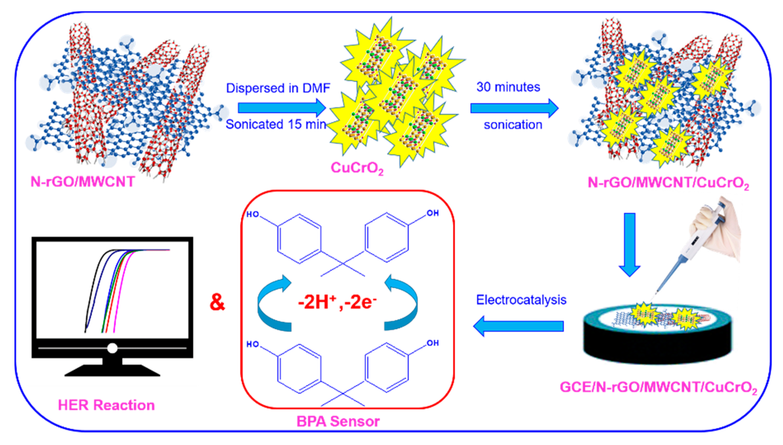
Synthesis of N-rGO-MWCNT/CuCrO2 Catalyst for the Bifunctional Application of Hydrogen Evolution Reaction and Electrochemical Detection of Bisphenol-A

by
Subramanian Sakthinathan
1,*,
Arjunan Karthi Keyan
1,
Ramachandran Rajakumaran
2,
Shen-Ming Chen
2,
Te-Wei Chiu
1,*,
Chaofang Dong
3 and
Sivaramakrishnan Vinothini
4
1
Department of Materials and Mineral Resources Engineering, National Taipei University of Technology, No. 1, Section 3, Chung-Hsiao East Road, Taipei 106, Taiwan
2
Department of Chemical Engineering and Biotechnology, National Taipei University of Technology, No. 1, Section 3, Chung-Hsiao East Road, Taipei 106, Taiwan
3
Corrosion and Protection Center, Key Laboratory for Corrosion and Protection (MOE), University of Science and Technology Beijing, No. 30 Xueyuan Road, Beijing 100083, China
4
Department of Computer Science and Information Engineering, National Taipei University of Technology, No. 1, Section 3, Chung-Hsiao East Road, Taipei 106, Taiwan
*
Authors to whom correspondence should be addressed.
Catalysts 2021, 11(3), 301; https://doi.org/10.3390/catal11030301
Submission received: 30 January 2021 / Revised: 21 February 2021 / Accepted: 23 February 2021 / Published: 25 February 2021

Abstract

:
A glassy carbon electrode (GCE) coated with delafossite CuCrO2 loading on the nitrogen-doped reduced graphene oxide (N-rGO) and multiwalled carbon nanotubes (MWCNT) composite (N-rGO-MWCNT/CuCrO2) was applied to the hydrogen evolution reaction and Bisphenol-A (BPA) detection. First, the N-rGO-MWCNT composite was prepared by in situ chemical reduction with caffeic acid as a reducing agent. Then, CuCrO2 was accumulated on the N-rGO-MWCNT surface to form N-rGO-MWCNT/CuCrO2 composite. The morphology structure of the N-rGO-MWCNT/ CuCrO2 composite was analyzed by different characterization techniques. Besides, the GCE/N-rGO-MWCNT/CuCrO2 composite electrode was investigated for hydrogen evolution reaction (HER), which shows an excellent electrocatalytic activity with a low over-potential, increasing reduction current, and a small Tafel slope of 62 mV·dec−1 at 10 mA·cm−2 with long-term stability. Moreover, the electrochemical determination of BPA was in the range of 0.1-110 µM, and low detection limit of 0.033 µM (S/N = 3) with a higher sensitivity of 1.3726 µA µM−1 cm−2. Furthermore, the prepared GCE/N-rGO-MWCNT/CuCrO2 electrode shows effective detection of BPA in food samples with acceptable recoveries. Hence, the finding of GCE/N-rGO-MWCNT/CuCrO2 can be observed as an impressive catalyst to the electrocatalytic activity of HER and BPA oxidation.

Graphical Abstract

1. Introduction

Increasing the energy crisis, environmental pollution, climate change, and energy shortages by excessive fossil fuel consumption, so the need to seek clean, cheap, safe and viable renewable energy resources has become very important [1]. Hydrogen (H2) has received considerable attention recently as a next-generation energy carrier. Besides, H2 is used as a fuel in automobiles, fuel cells, and aerospace industries by transforming chemical energy into electrical energy [2]. Moreover, H2 is one of the most efficient sustainable chemical fuels and preferred environmentally sustainable green energy carriers, which can provide fast various forms of energy in the future energy infrastructure [3,4]. Furthermore, H2 is a prospective fuel, it is produced as a by-product of the reaction of carbon dioxide with water. At present, the predominant method for H2 production is the non-renewable steam reforming process, which increases fossil fuel usage and carbon dioxide emission [1,5]. Among the other H2 production methods, water splitting technology is the most favorable, environmental-friendly, and efficient for H2 generation [6,7]. Besides, HER is the most promising solution due to its energy efficiency, sustainability, low cost, and the possibility for easy commercialization. Furthermore, water electrolysis is an environmentally sustainable technology that creates high-purity H2 flow, but the high energy consumption of this process is the major draw-back [8,9].
Water electrocatalysis has two half-reactions, producing H2 at the cathode component by the hydrogen evolution reaction (HER) and producing oxygen at the anode by the oxygen evolution reaction (OER) [10,11]. The produced H2 is used as a fuel and blended into the atmosphere with O2. Currently, Pt, Au, Ru, and Pd-based catalyst has been working as a superior HER process, but it has some flaws, such as high cost and the minimum amount of H2 output [6,7,10,11,12]. Therefore, alternative water electrolysis materials must be produced with an economical and effective catalyst relative to the aforementioned HER catalyst. For that reason, the best ways to mitigate manufacturing costs and reduce the over-potential of HER have also been evaluated with various electrocatalytic materials [13].
However, there is a significant problem of reducing the overpotential for OER and, among other criteria, improving catalyst density and stability [14]. Therefore, for renewable energy and the global economy, there is an immediate need to design a more successful and efficient electrocatalyst from earth-abundant materials for water electrolysis [15,16]. Presently, delafossite metal oxides have further consideration for applications due to the higher electrocatalytic activity and well metal-oxygen bond interaction [17,18].
The general formula of the delafossite structure is the ternary oxide composition of MIMIIIO2. It is split into two groups; monovalent cations (MI = Ag+ and Cu+) are the first and the trivalent cations (MIII = Al3+, Cr3+, Fe3+, In3+, Co3+) are the second [19,20]. The arrangement of the delafossite has the stacking layers of two tightly packed oxygen occupied by MIII cations, linked to form a triangular network by planes of MI cations. Two oxygen anions from the above and below planes linearly coordinate each MI cation. Depending on the size of the MIII cations, various oxygen intercalation spaces are required in the triangular network of MI cations [21,22]. Even though, CuCrO2 has more interest as compared with other ternary oxides due to their wide ranges of optical clarity and electrical conductivity [23]. However, the CuCrO2 complex has a low surface area so it is more important to boost the activity. Therefore, the CuCrO2 complex needs to be decorated with a highly active and broad surface area material [24,25]. The high surface area of carbon nanomaterials such as graphene, carbon nanofibers, and carbon nanotubes (CNTs) have been used to help these delafossite copper complexes for greater electrocatalytic activity [26,27,28].
Among the numerous carbon materials, reduced graphene oxide (rGO) has received more attention such as high surface area, interconnected macroporous structures, higher stability, and conductivity [29,30,31]. Now a day, various types of reduction methods are used to prepare rGO including chemical vapor deposition (CVD), epitaxial growth, mechanical exfoliation, electric arc discharge, and chemical reduction methods [32]. Among these aforesaid methods used a significant number of toxic reducing agents such as dimethylhydrazine, NaBH4, and hydrazine are used for the preparation of rGO [33,34]. Therefore, it is more important to define an environmentally friendly reductant to reduce Graphene oxide (GO) for the formation of rGO. Currently, eco-friendly chemicals have been used for the preparation of rGO [35]. For this reason, environmentally friendly caffeic acid (CA) is used for the rGO preparation. Besides, rGO has a high surface area; however, due to the low active sites, they have insufficient catalytic activity, hence it is more important to insert heteroatom on the graphene surface to increase the catalytic activity [36].
An introduction of nitrogen (N) on the rGO surface to be developed activation centers for HER [37]. However, N-rGO also has some defects owing to the interaction between the rGO sheets be aggregated and reduce the surface area [38]. To solve this problem, the N-rGO incorporated with MWCNT to inhibit the rGO aggregation and to enhance the surface area of the N-rGO-MWCNT composite [39,40]. Besides, these carbon composites have been used to increase the surface area and higher electron transfer of the CuCrO2 complex [41,42]. The ultrafine N-rGO-MWCNT/CuCrO2 composite was prepared and decorated on the polished GCE for the HER reaction. The obtained GCE/N-rGO-MWCNT/CuCrO2 electrode shows strong stability with efficient HER performance.
Bisphenol-A (BPA) is the key material for manufacturing epoxy resins, polycarbonate plastic, resins, and coatings on food material pockets [43,44]. Besides, BPA is one of the endocrine damaging compounds that are polluted by the milk bottles, landfill leachates, paper, packaging, and plastics industries in the environment [45]. In comparison, BPA not only impacts the growth of the fetus, but also raises the risk of diseases such as heart disease, diabetes, and cancer [46]. Therefore, a basic and sensitive technique for the detection of BPA is more important to create [47]. Various types of techniques, such as immune sensors, molecular imprinting process, high-performance liquid chromatography (HPLC), mass spectrometry, and electrochemical methods have currently been used to detect BPA [48,49]. Among these methods of detection, electrochemical BPA detection has greater attention with simple planning, low cost, rapid reaction, surface renewal ease, bulk adjustment, high sensitivity, and selectivity [50]. Electrode modification by various materials is the most important strategy for the electrochemical sensor. Hence, the GCE/N-rGO-MWCNT/CuCrO2 electrodes were used for the electrochemical detection of BPA. [51,52]. To investigate the limit of detection, stability, repeatability, interference ability, and practical application in the detection of BPA. The electrodes of GCE/N-rGO-MWCNT/ CuCrO2 demonstrated impressive electrochemical sensor properties and sensitivity in BPA detection. In this paper, the GCE/N-rGO-MWCNT/CuCrO2 electrode exhibited an excellent electrocatalytic response toward the HER and BPA detection.

2. Results and Discussion

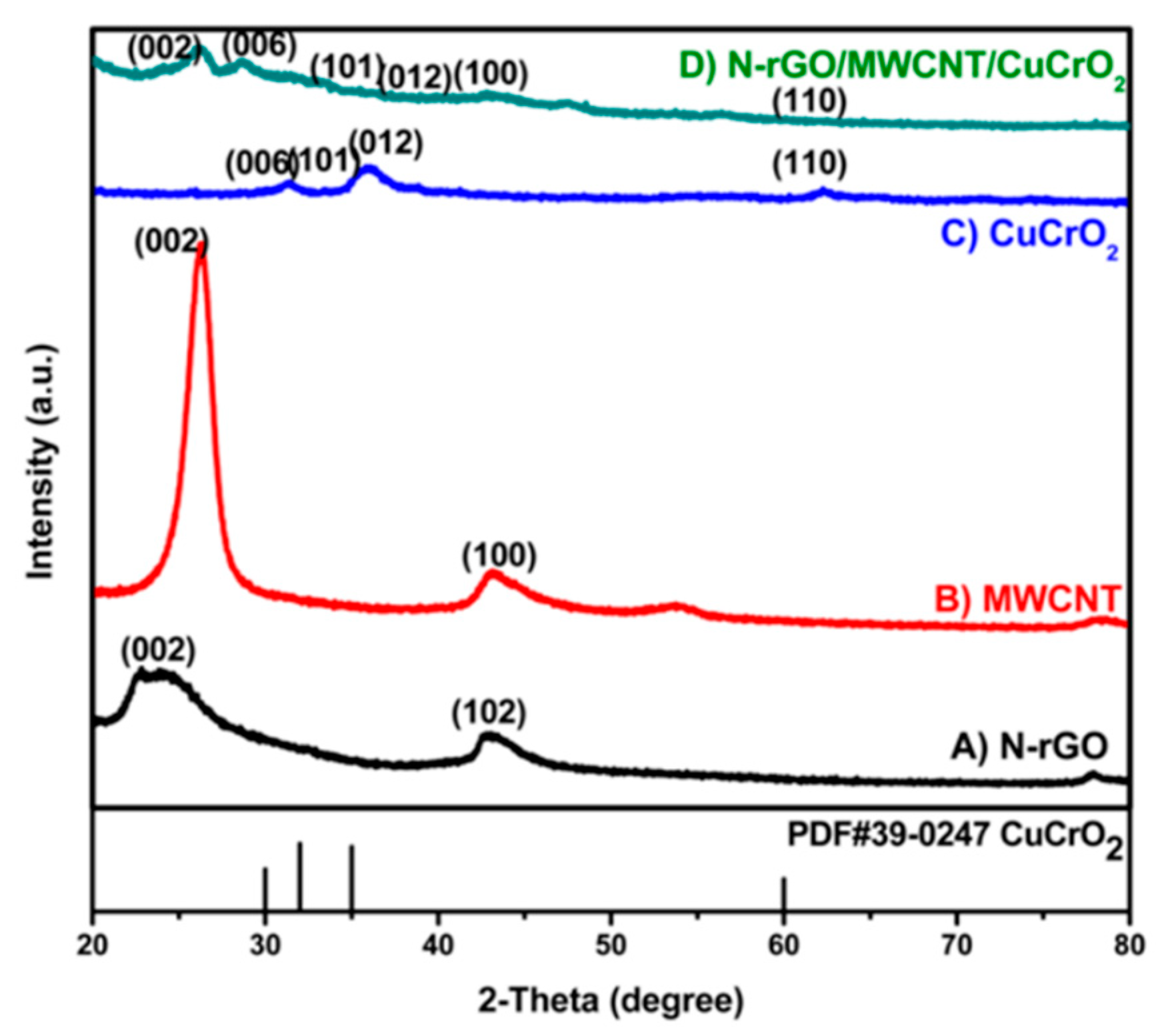
2.1. X-ray Diffraction (XRD) Studies

The XRD sequence of pristine (A) N-rGO, (B) MWCNT, (C) CuCrO2, and (D) N-rGO-MWCNT/CuCrO2 composites are shown in Figure 1. The XRD spectra of N-rGO illustrate a broad diffraction peak at 2θ = 24.8° for belongs to the (002) plane of amorphous nature hexagonal graphitic carbon. Besides, the typical XRD patterns of MWCNT display (002) and (100) peaks were found at 26.33° and 43.69°, respectively. Also, the reflective spectra of CuCrO2 complex were obtained at the 2θ values of 30.26°, 34.52°, 35.38°, and 62.55° corresponding to the (006), (101), (012), and (110) hexagonal crystal planes of CuCrO2 (JCPDS no: 740983, PDF#39-0247). This is following the previously finding CuCrO2 diffraction. The XRD pattern of the N-rGO-MWCNT/CuCrO2 composite observes the reflections corresponding to the N-rGO-MWCNT and CuCrO2 crystalline peaks validate that the composite formation.

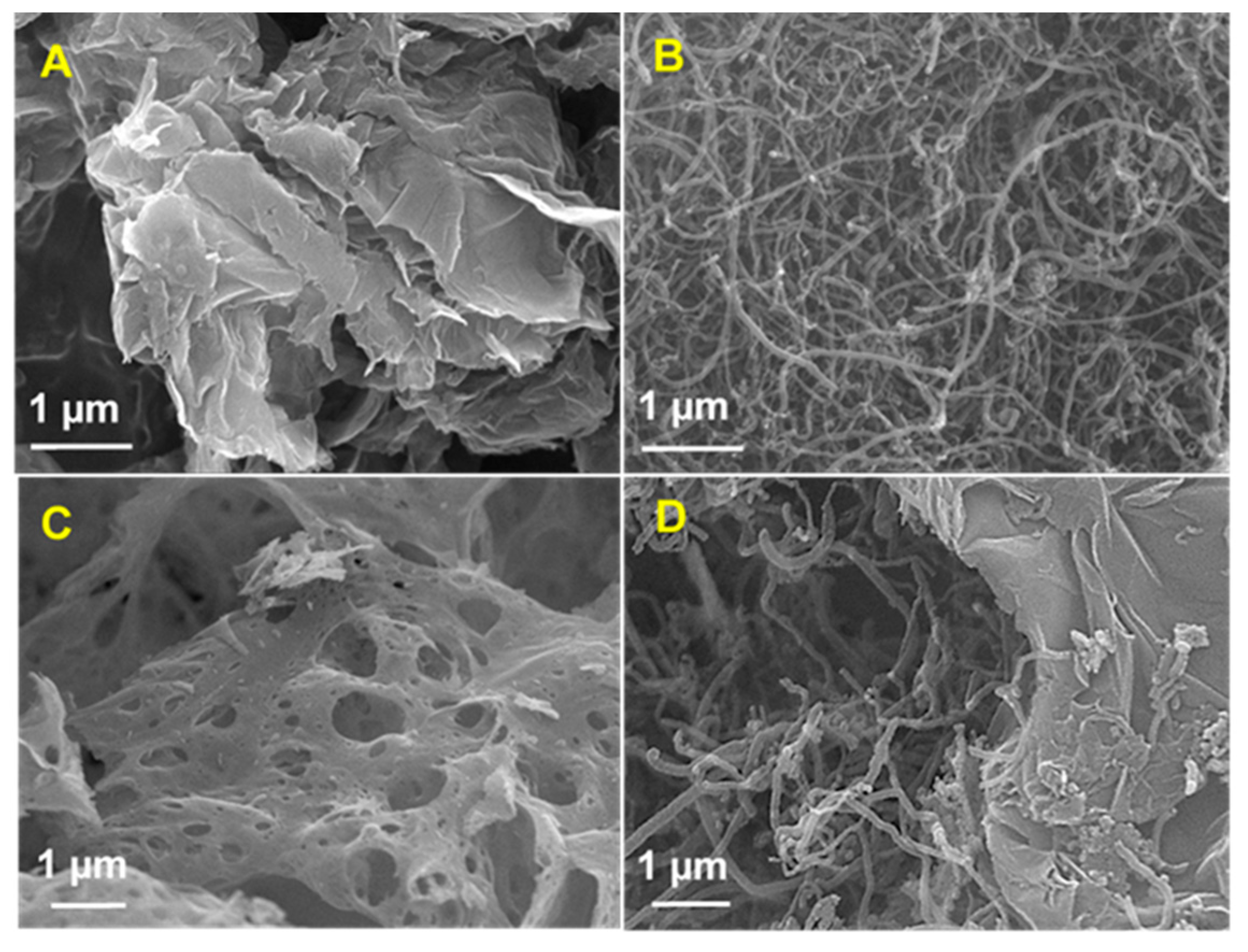
2.2. FESEM and EDX Studies

Figure 2 shows the field emission scanning electron microscope (FESEM) experiments that have identified the morphological composition of (A) N-rGO, (B) MWCNT, (C) CuCrO2, and (D) N-rGO-MWCNT/CuCrO2 composites. The FESEM morphologies of the N-rGO show good wrinkles and folding nanosheets on the top surface. Besides, transparent graphene nanosheets with a much more heavily wrinkled surface are seen by the N-rGO. The wrinkled structure raises the surface area of nanosheets and decreases the Π–Π stacking phase of their interlayer. Moreover, the FESEM image of the MWCNT indicates that the typical tube-like structures with the smooth surface of tangled tubes consisting of agglomerated structure. The surface of the tubes tends to be well-formed with increased thickness. On the other hand, the FESEM picture of CuCrO2 had a translucent, thick cotton-like texture. It was found that the CuCrO2 powder has emitted a significant volume of gas during the glycine-nitrate process (GNP). Finally, the FESEM images of the N-rGO-MWCNT/CuCrO2 composite reveals that the N-rGO-MWCNT surface is coated by a CuCrO2 complex. This indicating that the close interaction between the CuCrO2 and N-rGO-MWCNT composite. The N-rGO-MWCNT/CuCrO2 composite consists of N-rGO- MWCNT and CuCrO2 complex combined structure. A hierarchically porous interconnected structure with a wide internal surface area is illustrated by the N-rGO-MWCNT/CuCrO2 composite.

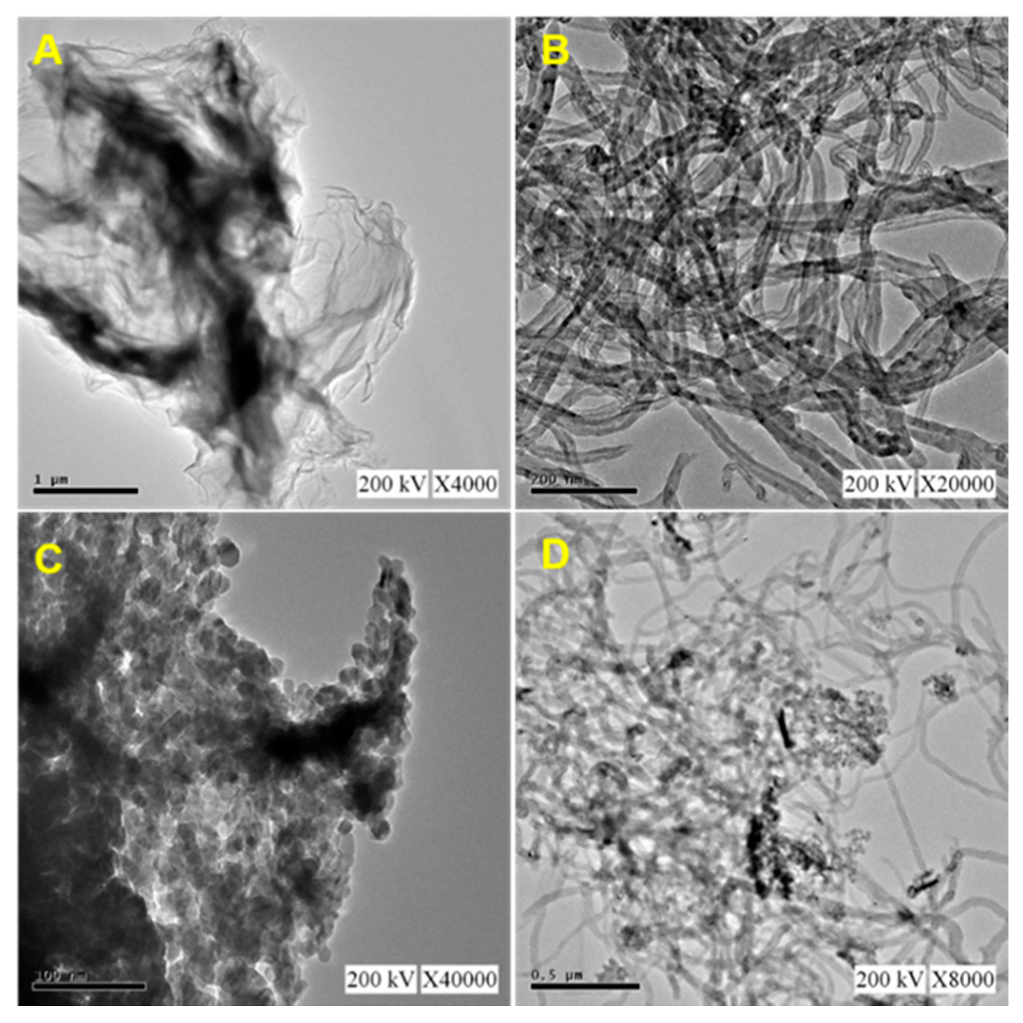
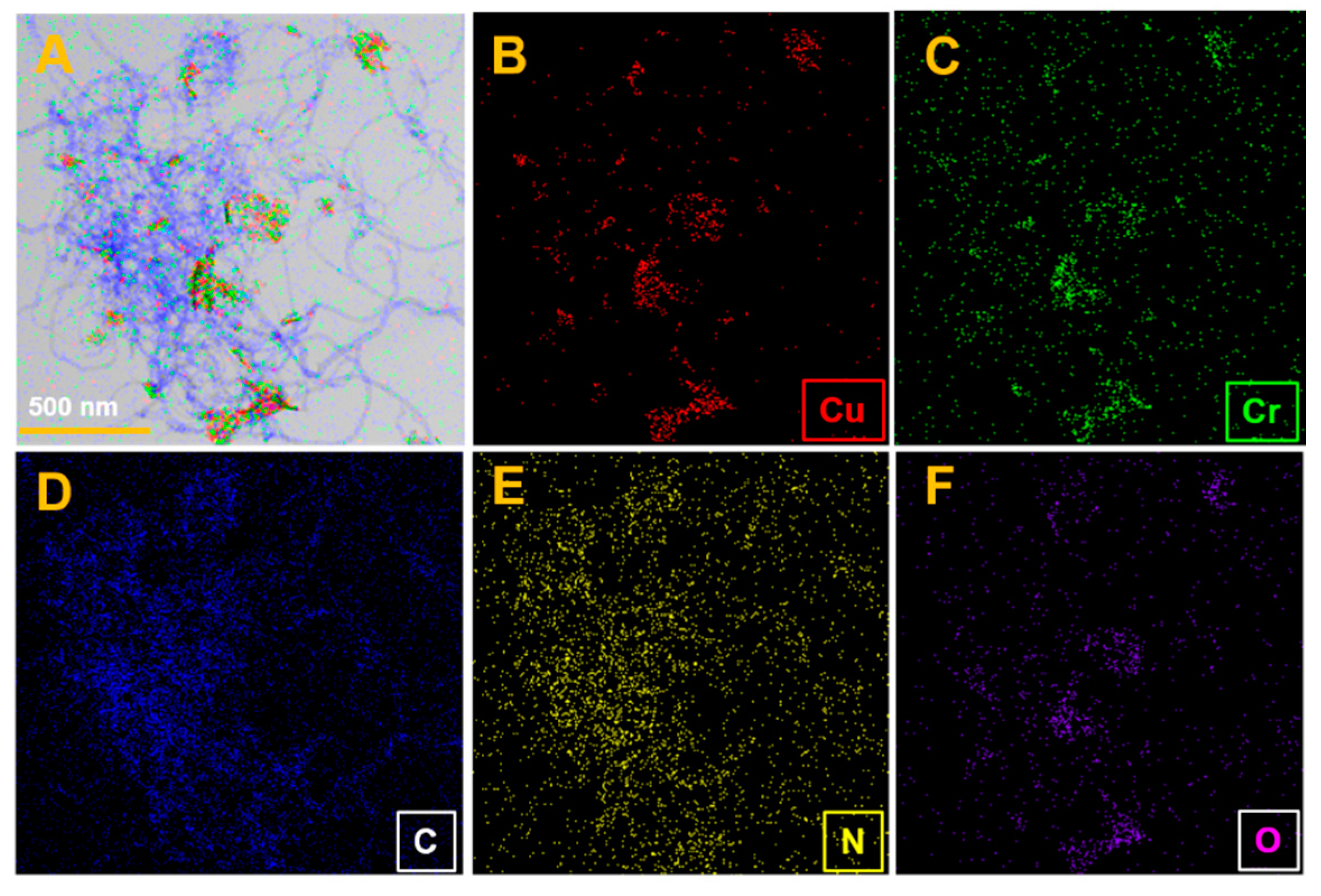
2.3. TEM and STEM Studies

Figure 3 shows a typical TEM image of (A) N-rGO, (B) MWCNT, (C) CuCrO2, and (D) N-rGO-MWCNT/CuCrO2 composite. TEM image of N-rGO revealed that transparent, edges, wrinkles, and folds that are curved. In the carbon sites, the observed edges may be due to the doping of nitrogen atoms. The TEM images of the MWCNT observe the tubular structures with the multiple walls and they agglomerate by reason of van der Waals interaction between the MWCNT. The narrow pipe wall structure was clear in the cross-section of the MWCNT. It is revealed that the inner cavity of the tunnel was hollow, which could potentially be used for modification. As exemplified the N-rGO-MWCNT/CuCrO2 composite shows the surface of N-rGO is covered by the well-dispersed CuCrO2 particles with uniform size. The TEM image CuCrO2 was firmly attached to the N-rGO-MWCNT composite. Based on the above results, the N-rGO-MWCNT composite is beneficial to anchoring CuCrO2 and effectively improve the composite formation. The morphological structure of CuCrO2 powder exhibits quasi-hexagonal agglomeration morphology. Besides, the crystalline size of the CuCrO2 particle was around 20 nm.
The N-rGO-MWCNT/CuCrO2 elemental distribution was evaluated by STEM-EDS, and the findings are mentioned in Figure 4A. All the elements (B) Cu, (C) Cr, (D) C, (E) N, and (F) O distributions were identical and they were well scattered. The elemental mapping findings that the composite has simple and well-dispersed regions due to the small size of the particles. The STEM-EDS spectrum confirms that the N-rGO-MWCNT/CuCrO2 composite has been successfully established.

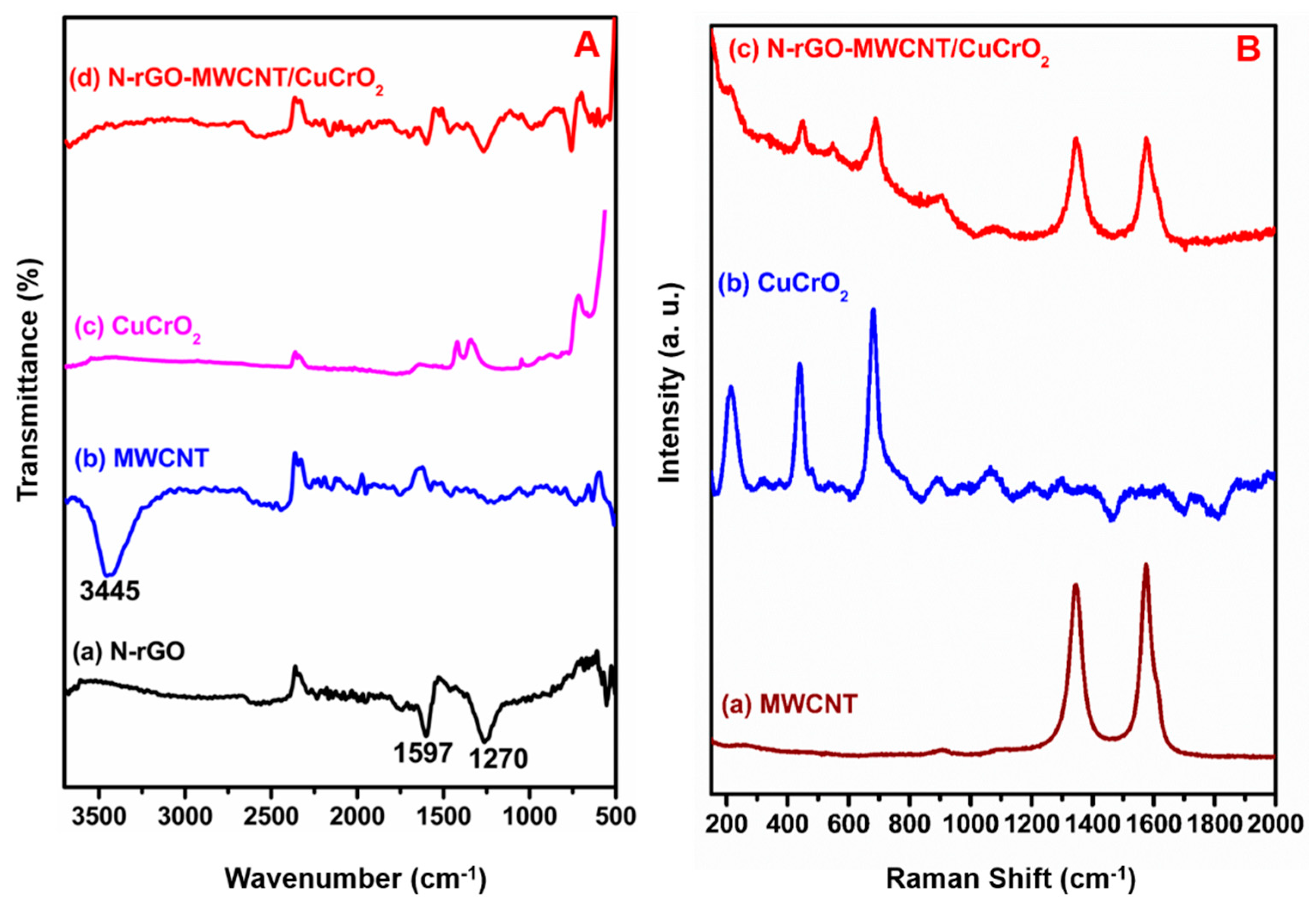
2.4. FT-IR and Raman Studies

Figure 5A displays the FT-IR spectra of (a) N-rGO, (b) MWCNT, (c) CuCrO2, and (d) N-rGO-MWCNT/CuCrO2. The FT-IR spectra of two absorption peaks at 1597 and 1270 cm−1 were seen by N-rGO, which can be a reason for the C=N and C-N bands, indicating that the successful formation of N-rGO. The FT-IR studies of MWCNT reveal peaks at 3500–3000 cm−1 for O-H stretch and 1747–1600 cm−1 for C=O stretching vibration. Besides, the bending motion of C-O and O-H displays at 1310–1010 cm−1 and 950–890 cm−1, respectively. Besides, the MWCNT displays a peak at 1680–1640 cm−1 for suggesting that stretching vibration of -C=C-. The FT-IR spectrum of CuCrO2 indicated that the absorption peak at about 3200–3500 cm−1 is delegated to the stretching vibration of the -OH groups. The absorption peaks at 1480 cm−1 were CH2 symmetric vibrations. The peaks of 1410 cm−1 and 1465 cm−1 are attributed to the symmetrical vibration of the N-CH3 and -C-H group, respectively. In the FT-IR spectra of stretching vibrations of Cr-O peak at 727 cm−1. Furthermore, the Cu-O bond absorption peak shows at 498 cm−1. Finally, the FT-IR spectrum of N-rGO-MWCNT/CuCrO2 composite exhibits the vibrational bands of the CuCrO2 to confirm the effective incorporation of the copper complex into the N-rGO-MWCNT composite.
Raman spectroscopy can be used to describe the structural properties of carbon materials. Figure 5B displays the Raman spectrum of (a) MWCNT, (b) CuCrO2, and (c) N-rGO-MWCNT/CuCrO2 composite have consisted of the number of distinct peaks. The Raman spectra of N-rGO shows at 1351 cm−1 and 1596 cm−1 can be attributed to the D and G bands, respectively. The distinctive D-band is indicated for breathing modes and the G-band is indicated for the vibrations mode of sp2 carbon (Figure S1). The Raman spectra of the MWCNT show two peaks were seen at about 1329 cm−1 (D-band) and 1575 cm−1 (G-band). The D-band refers to the disordered or sp3-hybridized carbons and the vibrations of sp2-bonded carbon atoms in MWCNT are assigned to the G-band. The Raman spectra for the CuCrO2 sample show the peaks at 212, 447, 561, and 698 cm−1 for the c-plane. Besides, the N-rGO-MWCNT/CuCrO2 composites could also be confirmed by the Raman spectra. The G-band of the N-rGO changes to 1585 cm−1 and the D-band is transferred to 1357 cm−1. Compared with N-rGO, MWCNT, and CuCrO2, the D-band of N-rGO-MWCNT/CuCrO2 shifts from 1335–1360 cm−1, while the G-band shifts from 1600–1610 cm−1, indicating the effective interaction between N-rGO-MWCNT composite and CuCrO2. The N-rGO-MWCNT/CuCrO2 composite intensities ratios slightly decreased from N-rGO, MWCNT, and CuCrO2, respectively. For the reason that the decrease in the sp2 domain size of carbon atoms during the chemical reaction. The G-band of N-rGO-MWCNT/CuCrO2 composite peak is moved relatively to that between N-rGO-MWCNT composite and CuCrO2 due to the Π–Π interaction.

2.5. XPS Studies

The chemical compositions and morphological structure of the N-rGO-MWCNT/CuCrO2 composite were studied by X-ray photoelectron spectroscopy (XPS). Figure 6A shows the full-scale survey XPS spectrum of Cu, Cr, O, C, and N indicating the formation of single-phase N-rGO-MWCNT/CuCrO2. The N-rGO-MWCNT/CuCrO2 composite XPS survey spectra were observed at 932 eV, 289 eV, 533.6 eV, 576 eV, and 397 eV for Cu, C, O, Cr and N, respectively (Figure 6B–F). The XPS results show binding energies at 286.2 eV and 288.2 eV represent C–N and HN–C=O, respectively. The main peak centered at 284.8 eV could be attributed to sp2 hybridized C atoms in the reduced graphene oxide, and the left part can be resolved into three components centered at 285.5, 288.3, and 289.9 eV, which can be assigned to N–sp2C, –C=O, and -COOH, respectively. The finding confirms that the N atoms were well binding onto the rGO surface. Besides, Cu2+ can be easily determined by the satellite peaks for the binding energy of the 2p−13d9 state. Two extreme peaks located at around 952.2 and 932.5 eV are observed, which can be assigned to Cu 2p1/2 and Cu 2p3/2 as seen in the Cu2p core level range. Furthermore, they appeared very weak satellite peaks due to the small level of Cu2+ and Cu0 species in the samples. The XPS spectra of Cr 2p consist of Cr 2p3/2 and Cr 2p1/2 peaks that are situated at 576 eV and 586 eV, in good agreement with previous literature. Finally, the XPS studies of CuCrO2 mentioned that the Cu and Cr are in +1 and +3 electronic states. Hence, the above XPS results are strongly confirmed that the successful formation of the N-rGO-MWCNT/CuCrO2 composite.

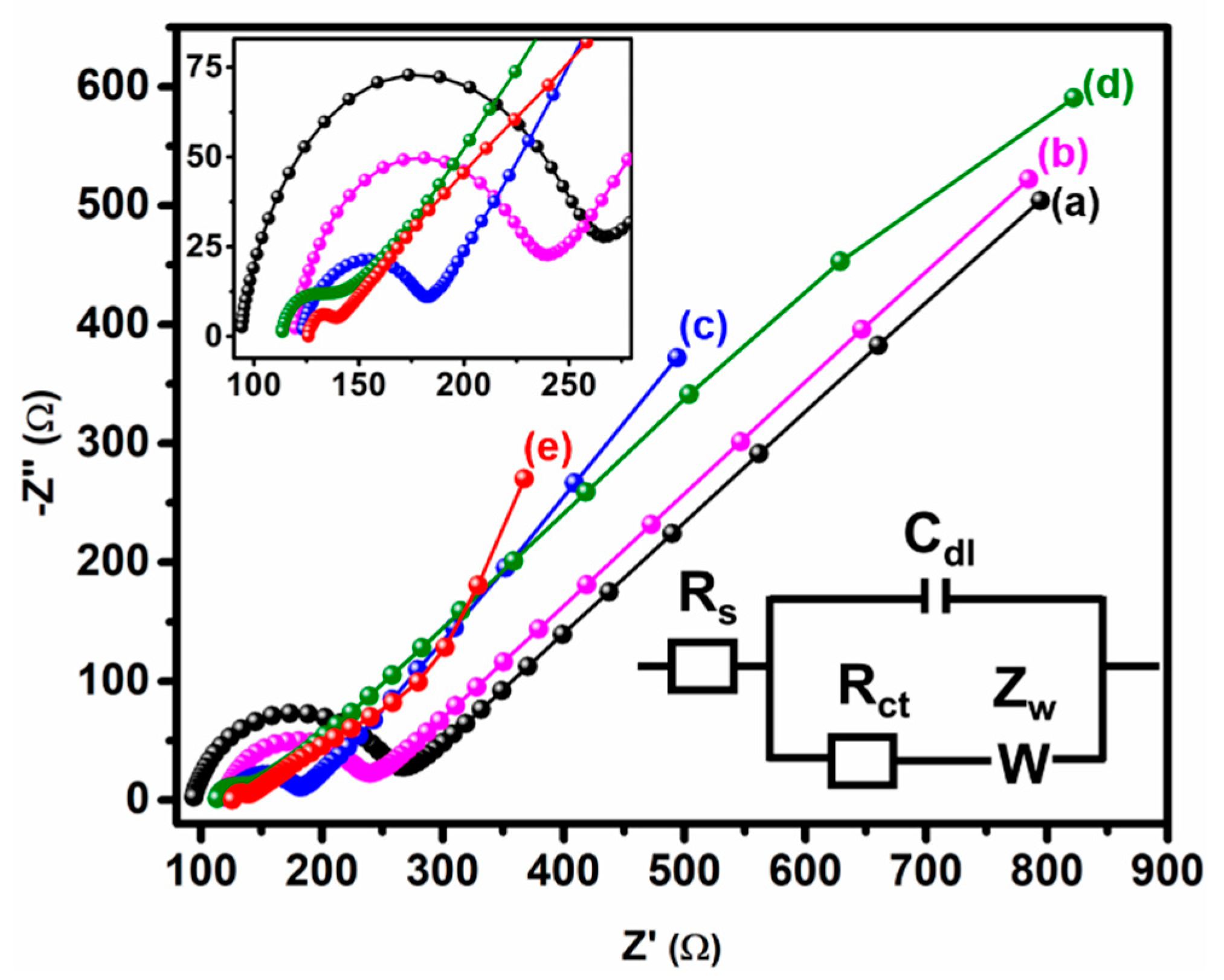
2.6. Electrochemical Impedance Spectroscopy Studies

Electrochemical impedance spectroscopy (EIS) has become a valuable method for studying the electrode interface charge transfer. Figure 7 shows the EIS Nyquist map of bare (a) GCE, (b) GCE/MWCNT, (c) GCE/CuCrO2, (d) GCE/rGO, and (e) GCE/N-rGO-MWCNT/CuCrO2 electrodes was obtained in a 5.0 mM [Fe(CN)6]3−/4− solution containing 0.1 M KCl at 100 mHZ to 100 KHz frequency. The plot typically consists of two zones namely the linear zone and semicircle zone. A typical Nyquist plot indicating that the semicircle section described the electron transfer resistance at a higher frequency and the linear section described the diffusion-limited process on the electrode at a lower frequency. It is observed that the bare GCE exhibits an Rct value of 175.12 Ω for the poor electron transfer of the GCE electrode surface. The GCE/MWCNT and GCE/CuCrO2 electrode show the Rct value of 121 Ω and 62 Ω, respectively. The obtained Rct value of GCE/MWCNT and GCE/CuCrO2 electrode is lower than the bare GCE. Furthermore, the GCE/N-rGO electrode Rct value of 27.44 Ω is lower than GCE, GCE/MWCNT, and GCE/CuCrO2 electrode. Because the GCE/N-rGO electrode has lower resistance and has a large surface area is attributed to the higher conductivity on the electrode surface. After that, the GCE/N-rGO-MWCNT/CuCrO2 electrode significantly delivers a very low Rct value of 13 Ω for the synergistic effect of CuCrO2 and N-rGO-MWCNT. Besides, this suggested that the N-rGO accelerated the electron transfer and CuCrO2 increase the electrocatalytic activity the GCE/N-rGO-MWCNT/CuCrO2 electrode was decorated on GCE. After that, the synergistic effect of the GCE/N-rGO-MWCNT/CuCrO2 electrode substantially offers a very low Rct value than other modified electrodes. In addition, this mentioned that the electron movement was accelerated by the N-rGO-MWCNT and CuCrO2 enhanced the electrocatalytic reaction in the GCE/N-rGO-MWCNT/CuCrO2 electrode.

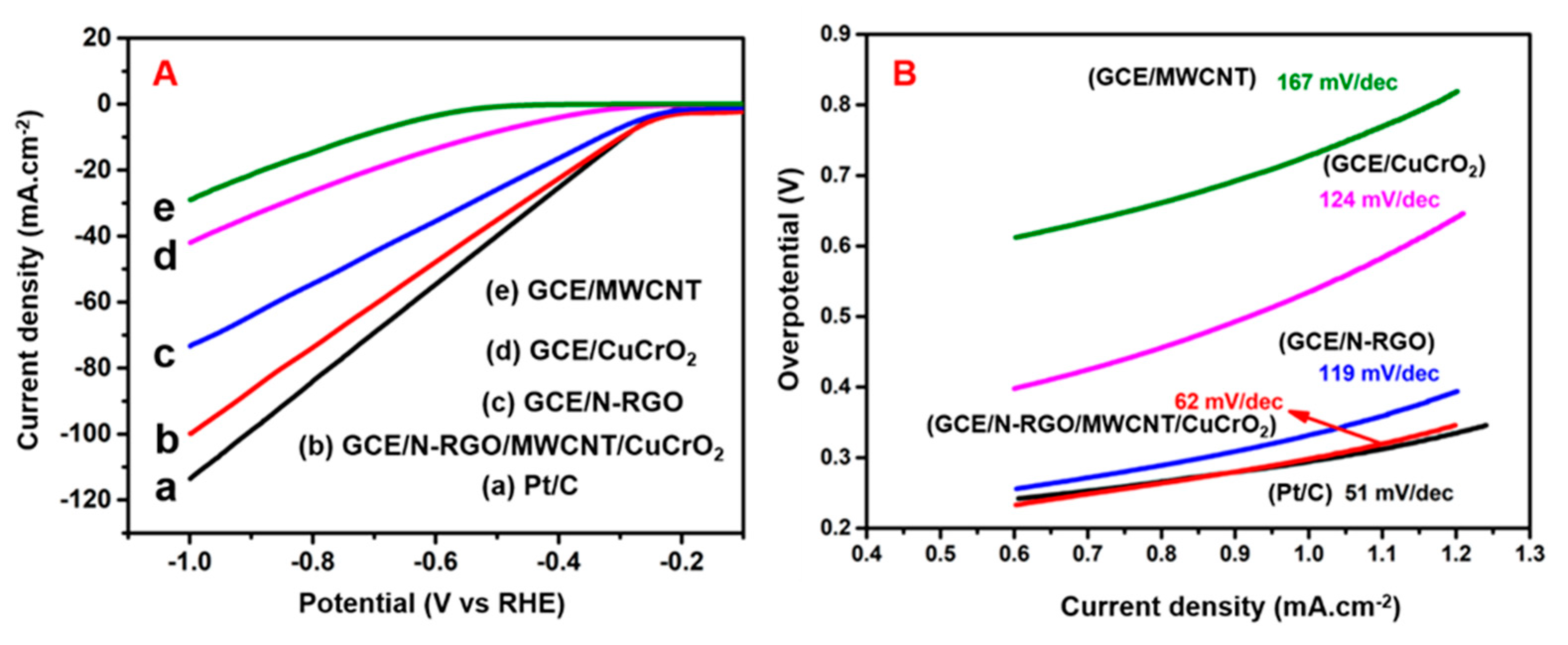
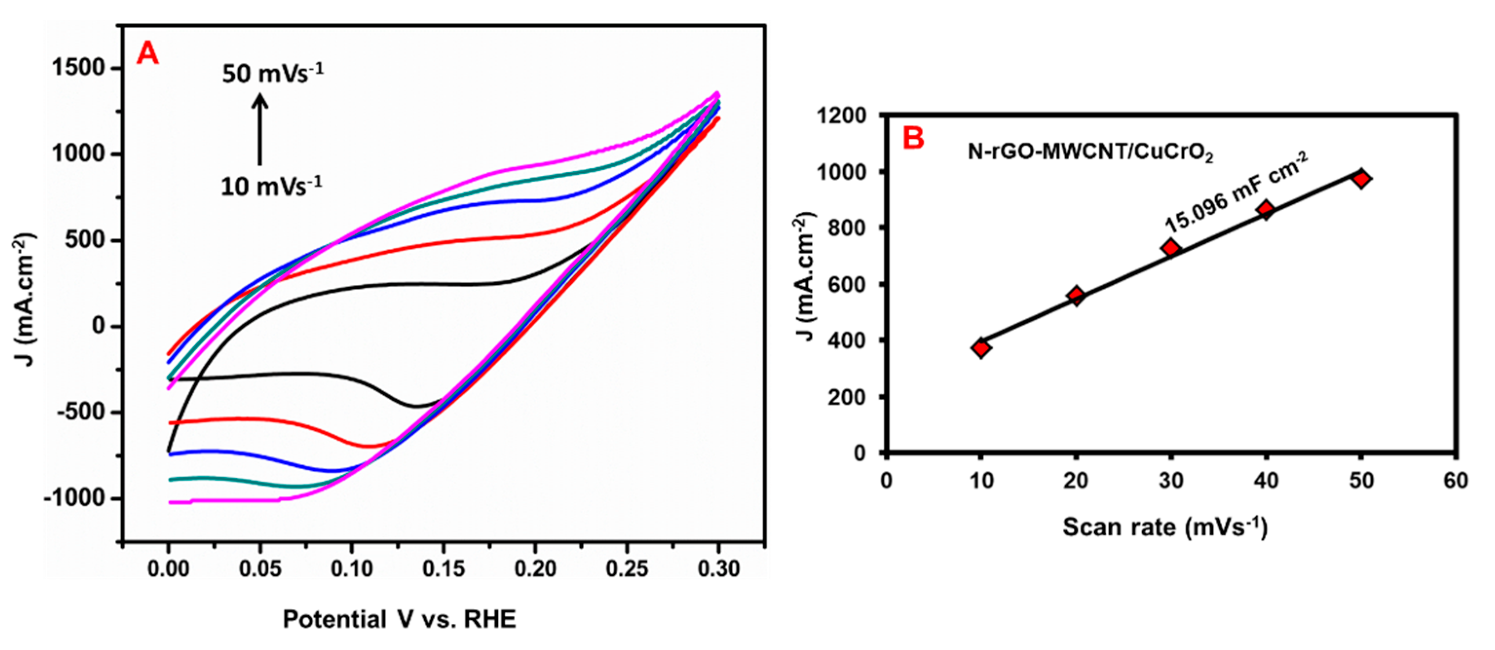
2.7. Hydrogen Evolution Reaction

The electrocatalytic hydrogen evolution reactions (HER) performance of N-rGO-MWCNT/CuCrO2 were conducted in N2-saturated 0.5 M H2SO4 versus Ag/AgCl by linear sweep voltammetry (LSV) studies and compared with N-rGO, CuCrO2, MWCNT, and Pt/C catalysts. As shown in Figure 8A, LSV polarization studies of the N-rGO-MWCNT/ CuCrO2 catalyst specifically indicated high-efficiency performance with a lower potential of around −198 mV at 10 mA·cm−2. The N-rGO-MWCNT/CuCrO2 composite was obtained higher current density compared with N-rGO, CuCrO2, and MWCNT catalysts and close to the industrial Pt/C catalyst. The low onset potential of the N-rGO-MWCNT/CuCrO2 composite in the cathodic region demonstrates high electrocatalytic performance. The cathodic region over-potential of the GCE/N-rGO, GCE/CuCrO2, GCE/MWCNT was observed to be approximately −378 mV, −410 mV, −570 mV at a current density of 10 mA·cm−2. This is also indicating that the current density is directly proportional to the evolution of the volume of hydrogen. The corresponding HER reaction at the cathode part is
2H2O + 2e → H2 + 2OH
The high HER performance of GCE/N-rGO-MWCNT/CuCrO2 is shown by the Tafel slopes. The Tafel slope values determined from LSV curves indicate that the 62 mV·dec−1 slope of the N-rGO-MWCNT/CuCrO2 catalyst is much lower than that of the rGO (119 mV·dec−1), CuCrO2 (124 mV·dec−1), and MWCNT (167 mV·dec−1). However, the commercial Pt/C catalyst indicates the slope value of 51 mV·dec−1 as shown in Figure 8B. Note that the bubble formation during the HER reduces the active surface area and the electrode Ohmic resistance. As observed with N-rGO, CuCrO2, and MWCNT, these variables can distort the Tafel slope. The low Tafel slope indicates that the HER on the N-rGO-MWCNT/CuCrO2 catalyst pursues the Volmer-Heyrovsky reaction with a rate-limiting process of desorption.
To identify the electrochemically active surface areas (ECSA) for electrodes were identified by Cyclic Voltammetry (CV) curves were recorded under non-Faradaic potential range. The electrochemical double-layer capacitance (Cdl) is used to evaluate the ECSA of the electrode. As mentioned in Figure 9A, the CV response of N-rGO-MWCNT/CuCrO2 was identified at various scan rates (10–50 mVs−1). The capacitive currents of the electrode were calculated in a potential range and the faradic process was not observed. The obtained CV peak currents were plotted for different scanning rates and the slope is shown in Figure 9B. The N-rGO-MWCNT/CuCrO2 electrodes have the highest Cdl versus RHE compared with other electrodes, inferred that the efficient active sites, high surface area, and their remarkable catalytic activity for HER.
The long-term stability performance of the N-rGO-MWCNT/CuCrO2 catalyst was examined by the CV and chronoamperometry test. The stability of the N-rGO-MWCNT/ CuCrO2 catalyst was studied under continuous tests during the HER process. As mentioned in Figure 10A, the cathodic current polarization curves show a small change and consistently high current density after 1000 cycles. The negligible variations between the starting CV curves and after 1000 cycles of CV curves, these CV studies suggest that the N-rGO-MWCNT/CuCrO2 has excellent electrochemical stability in HER.
Besides, the polarization curve is shown as a sawtooth shape due to the continuous accumulation and release of H2 on the catalyst surface during the HER process. The chronoamperometry (CA) curve with the overpotential is seen in Figure 10B, it exhibits no cathodic current loss over 6 h of electrolysis. After 6 h chronoamperometry run, the current density slightly degraded from the initial which could be attributed to consumption of H+ ions and the accumulation of H2 bubbles on the electrode surface to impede the reaction. It indicates the remarkable structural stability of N-rGO-MWCNT/CuCrO2 during the HER process.

3. Electrochemical Detection Performance of BPA

3.1. Different Film and Effect of Different Concentration Studies

The electrochemical efficiency of the electrode was examined by CV studies and compared to other electrodes for the sensing of BPA. Figure 11A displays the standard CV curves of the (a) bare GCE, (b) GCE/MWCNT, (c) GCE/CuCrO2, (d) GCE/N-rGO, and (e) GCE/N-rGO-MWCNT/CuCrO2 electrode in the existence of 10 μM of BPA in PBS solution (pH 7.0) at a scan rate of 50 mVs−1 in the +0.2 to 1.0 V potential range. The bare GCE does not show a BPA detection response, which indicates a very low direct electron transfer of BPA to the bare GCE. After that, the GCE/MWCNT electrode subsequently demonstrated BPA response at 0.553 V with a current density response of −46.58 µA. The GCE/CuCrO2 modified electrode exhibited a significant anodic peak at 0.535 V with a current density response of −62.11 µA, which could be due to the enhanced electron transfer of CuCrO2. The GCE/N-rGO modified electrode achieved better performance with a higher anodic peak current of −90.22 µA at 0.544 V compared to GCE, GCE/MWCNT, and GCE/CuCrO2 due to the remarkable electrocatalytic performance. Remarkably, the GCE/N-rGO-MWCNT/CuCrO2 electrode exhibited a high anodic peak of −134.6 µA at 0.557 V for BPA detection may be due to this large surface area of N-rGO-MWCNT and high electrocatalytic activity of CuCrO2. Moreover, Figure 11B the GCE/N-rGO-MWCNT/CuCrO2 composite electrode was compared to unmodified GCE, the composite modified electrode shows the high responsibility toward the detection of BPA. Therefore, at the optimal conditions, the GCE/N-rGO-MWCNT/CuCrO2 electrode had higher electrochemical activity, faster electron transfer rate, and higher conductivity.

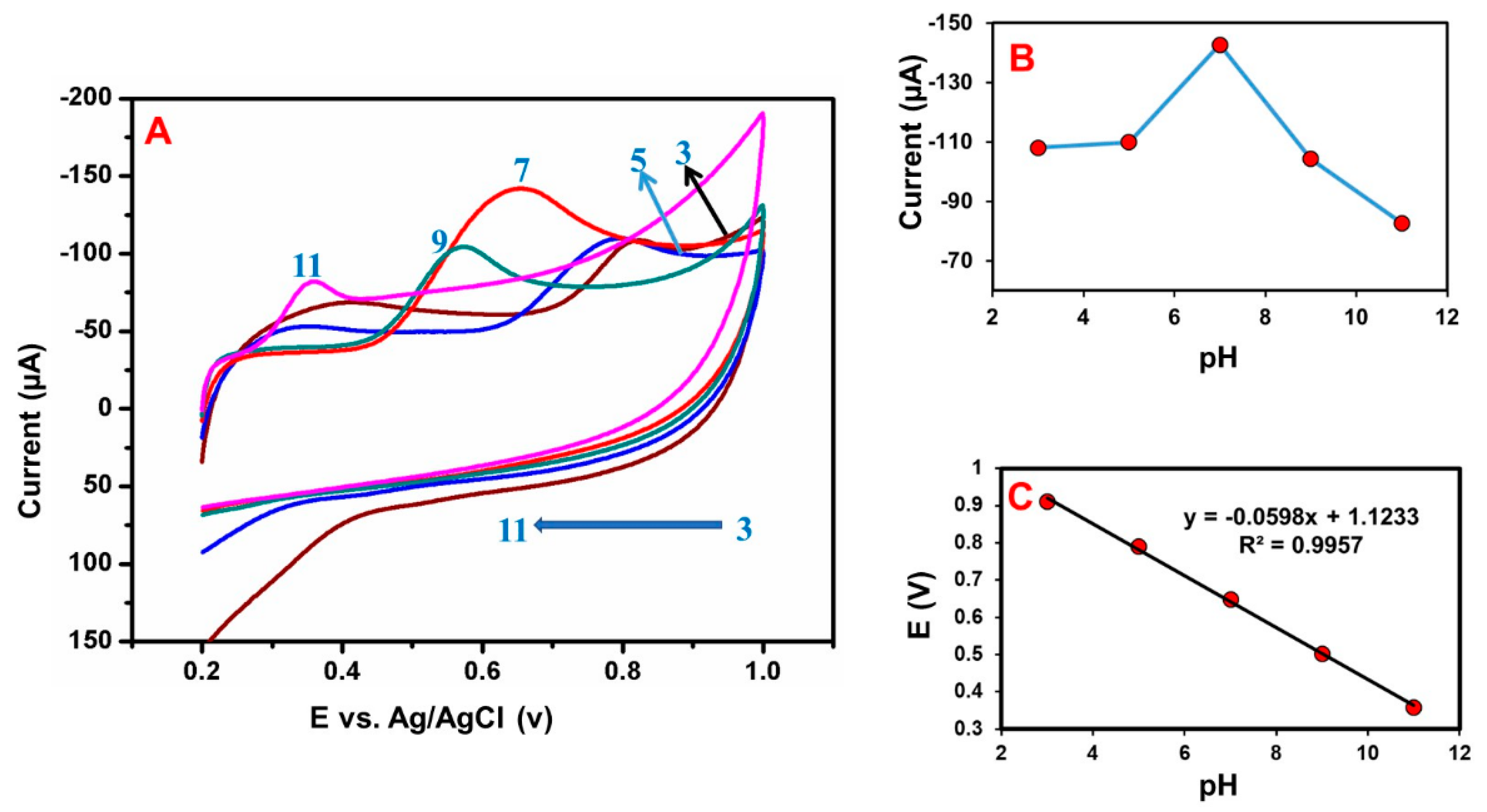
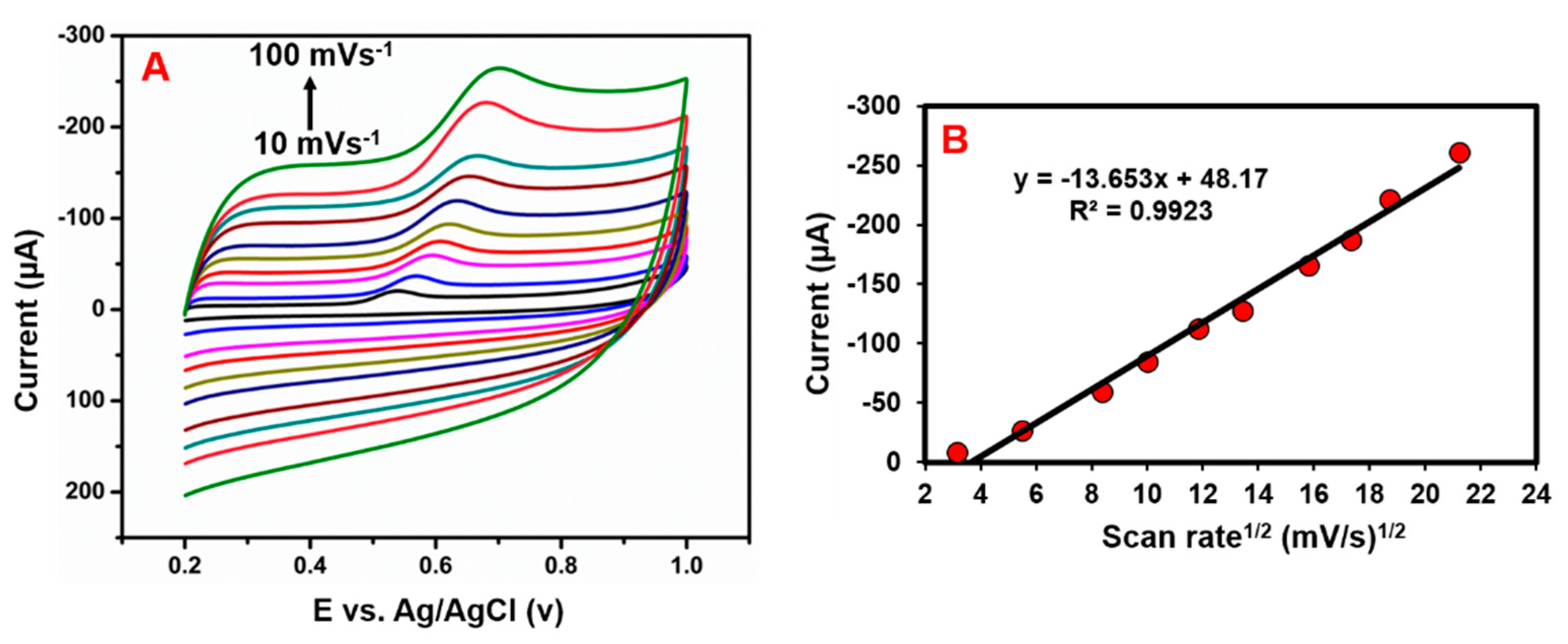
3.2. Effect of Different pH and Scan Rate Studies

The electrolyte pH condition is a significant parameter for the electrochemical sensor. Figure 12A shows, the effect of electrolyte pH value on the electrochemical detection of BPA by using CV. The electrolyte pH changed from 3.0 to 11.0 enhanced the BPA detection response, and achieved a higher peak current at pH of 7.0, after which it decreased (Figure 12B). This finding shows that hydronium ions play a vital role in BPA oxidation. The anodic peak potential of the electrolyte solution depends on the pH. Hence, the pH 7.0 was fixed as the electrolyte pH condition for further experiments. Moreover, Figure 12C shows, increasing the electrolyte pH condition; the anodic peak potential (Epa) of BPA detection was moved to the negative side and obtained the following linear correlation coefficient value of 0.9957 and slope value of –59.8 mV/pH. The slope value was almost similar to the theoretical value due to the deprotonation involved in the oxidation at pH 7.0. Based on the Nernst equation and the slope value, suggested that the same number of electrons and protons were involved in the detection of BPA [48,49,50].
Evaluate the influence of the scan rate (10–90 mVs−1) on the GCE/N-rGO-MWCNT/ CuCrO2 electrode toward the detection of BPA (Figure 13A). The electrochemical reaction is normally obtained from the correlation between the rate of the scan and the peak current. Hence, the effect of the scan rate on BPA oxidation at the GCE/ N-rGO-MWCNT/CuCrO2 was then explored by CV. Figure 13B suggests that BPA’s oxidation peak currents steadily increased to increase the scan rate by 10–100 mVs−1 and demonstrated a linear relation amid the BPA response current and the corresponding scan rate. The equation of linear regression could be expressed as Ipa (µA) = −13.653 (mVs−1) + 48.17 with the correlation coefficient of 0.9923. Besides, the BPA oxidation potential had a positive shift for increasing scan rate. This result shows that electrochemical oxidation of BPA over the GCE/N-rGO-MWCNT/CuCrO2 electrode is normal and regulated by the diffusion process.
Epa = E0 + [RT/αnF]In[RTK0/αnF] + [RT/αnF]Inυ
where Epa was the linear correlation, k0 was rate constant, α was transfer coefficient, n indicated electron transfer number, E0 was the redox potential, υ was the scanning rate, R denoted the gas constant, F was the Faraday constant and T was temperature. According to the linear relation, the slope was equal to RT/αnF. The scan rate studies demonstrate an equal number of electron and protons transfer reactions [53]. In that, the scan rate studies suggested that the reaction of BPA could be represented as consisting of one proton and one electron transfer reaction.

3.3. DPV Performance of Bisphenol-A on the GCE/N-rGO-MWCNT/CuCrO2 Electrode

Differential pulse voltammetry (DPV) is a more sensitive tool for identifying linearity, sensitivity, and electrode detection limits than other cyclic voltammetry systems. The electrocatalytic effect of GCE/N-rGO-MWCNT/CuCrO2 on the BPA oxidation had been identified by the DPV technique. Figure 14A shows DPV responses of BPA detection over the GCE/N-rGO-MWCNT/CuCrO2 in 0.05 M PBS with various concentrations addition of BPA. The relationship between the concentration and peak oxidation currents of BPA on the GCE/N-rGO-MWCNT/CuCrO2 was analyzed here by DPV and the result is mentioned in Figure 14B. The peak current of BPA oxidation linearly increased to increase the BPA concentration within the 0.05–10 μM range. Besides, the relation amid the concentration of BPA and the peak current of oxidation was seen as Ipa (μA) = −0.4118 + 57.308 (R2 = 0.9904). Also, the limit of detection (LOD) was calculated by the following formula LOD = 3 S/b; here, b is the slope of the calibration curve and S is the normal peak current deviation. The LOD was measured to be 0.033 μM and the electrode sensitivity was 1.3726 µA µM−1 cm−2, which exceeded the various forms of BPA sensors previously mentioned, as defined in Table S1. The superior electrocatalytic activity of CuCrO2 and the large specific surface area of the N-rGO-MWCNT composite establish strong electron transfer capability and sensitivity of GCE/N-rGO-MWCNT/CuCrO2 electrode. Therefore, the electrochemical results show that GCE/N-rGO-MWCNT/CuCrO2 electrode had a linear concentration range, a lower detection limit, and an appropriate sensitivity for BPA detection. Thus, the GCE/N-rGO-MWCNT/CuCrO2 electrode can be used for the real-time detection of trace amounts of BPA in food samples.

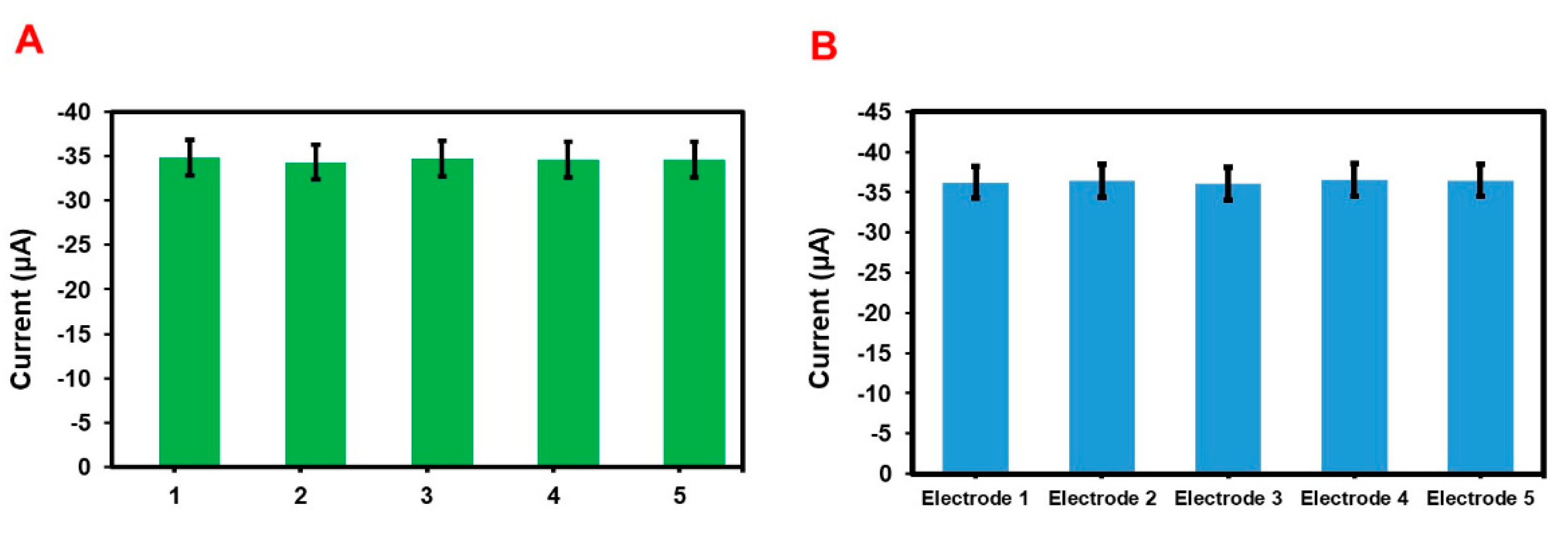
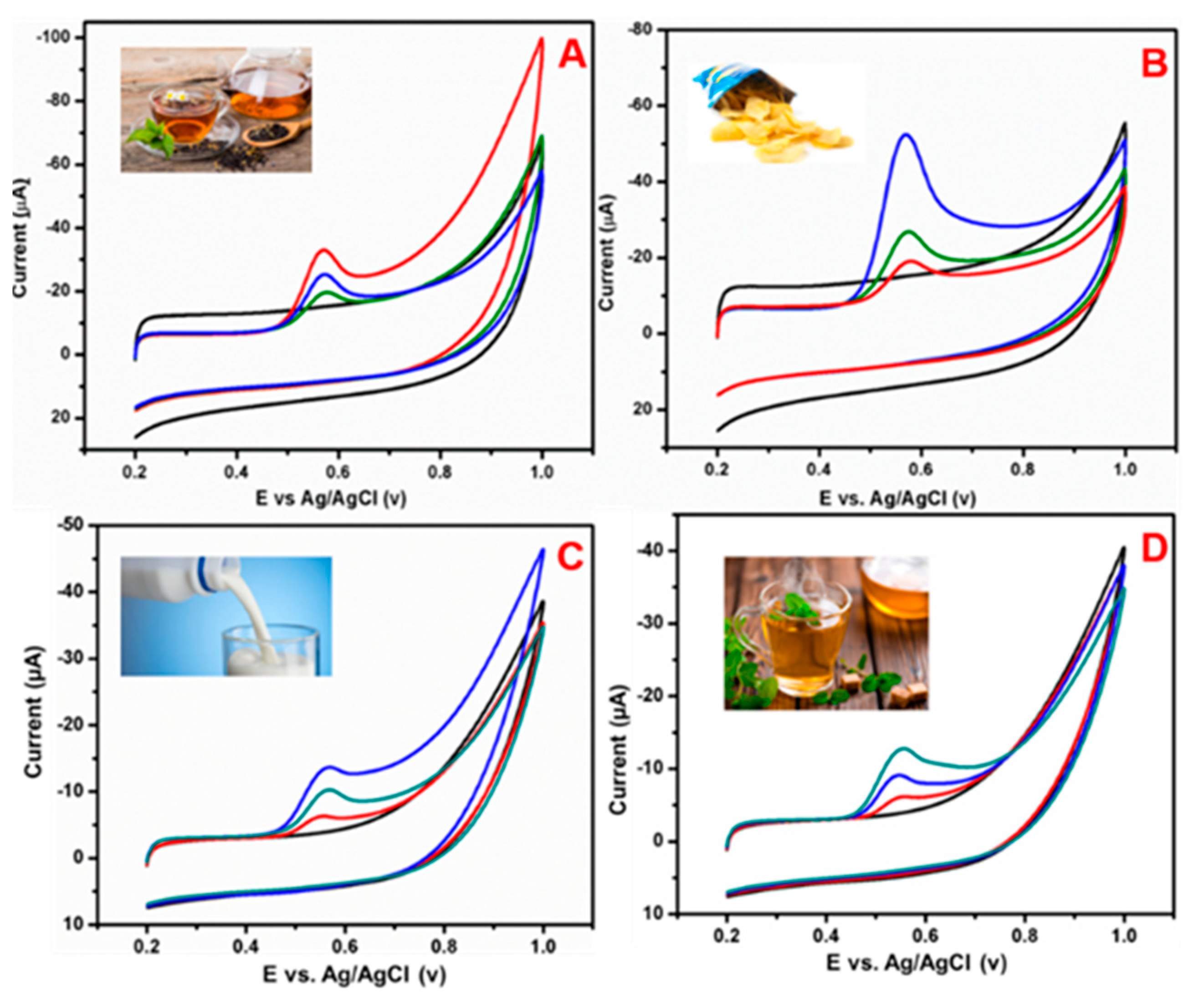
3.4. Selectivity, Stability, Repeatability, Reproducibility and Real Sample Studies

The selectivity performance of the GCE/N-rGO-MWCNT/CuCrO2 electrode was studied under the optimal condition by the CV in the 20 µM of BPA presence in PBS solution together with certain interference molecules and ions such as the 5-fold concentration of other similar chemicals such as phenol, p-nitrophenol, hydroquinone, resorcinol, ascorbic acid, dopamine, and uric acid. Also 10-fold higher concentration of metal ions such as Ca2+, Na+, Mg2+, Fe3+, NO3−, I, SO42− and PO43− etc. The GCE/N-rGO-MWCNT/CuCrO2 electrode shows that the BPA response was observed without any loss in the presence of different interfering molecules and metal ions. The results prove that the GCE/N-rGO-MWCNT/CuCrO2 electrode might be suitable for the selective detection of BPA. Moreover, the operational stability behavior of the electrode was studied by a CV technique in the presence of 20 µM BPA. The experimental performance shows a BPA peak current loss of only 2.5% from the initial BPA response peak current. The obtained results show that the GCE/N-rGO-MWCNT/CuCrO2 electrode has better operational stability.
Repeatability and reproducibility properties of the GCE/N-rGO-MWCNT/CuCrO2 electrode were carried out by cyclic voltammetry in PBS including 20 µM BPA. Figure 15A shows the repeatability studies of the electrode shown an acceptable percentage of current performance with 2.32% for five repeated measurements studied by using a single GCE/N-rGO-MWCNT/CuCrO2 electrode. Besides, the GCE/N-rGO-MWCNT/CuCrO2 electrode exhibits reasonable reproducibility of 2.74% for five independent electrochemical studies by the five different modified electrodes (Figure 15B). These performances show more evidence that the GCE/N-rGO-MWCNT/CuCrO2 electrode has excellent repeatability and reproducibility behaviors. All of the above studies state that the GCE/N-rGO-MWCNT/CuCrO2 electrode has remarkable selectivity, stability, repeatability, and reproducibility behavior.
Figure 16 shows the BPA real sample analysis of the GCE/N-rGO-MWCNT/CuCrO2 electrode was identified by the DPV technique using (A) green tea, (B) chips, (C) milk and (D) coffee samples. The food samples were obtained from the local market in Taipei and used for real sample analysis. The real sample studies exhibit that the food samples did not identify any BPA response without the addition of BPA, which indicated that the BPA concentration is lower in food samples than the detection limit. For this reason, the recommended addition methods were used to recover the actual real sample analysis under the optimized condition, and the results are represented in Table 1. From the real sample analysis, the GCE/N-rGO-MWCNT/CuCrO2 electrode shows an admissible recovery percentage between 93–99.0%. Therefore, these results indicate that the GCE/N-rGO-MWCNT/CuCrO2 electrode has efficient for real sample analysis.

4. Experimental

4.1. Materials and Methods

Multiwalled carbon nanotube (MWCNT) (>95% purity, 10–20 nm diameter), sulfuric acid (H2SO4) (95% purity), nitric acid (HNO3) (69.5% purity), graphite (<20 μm), copper chloride (99% purity), chromium (III) nitrate (99% purity), and caffeic acid (≥98% purity) were acquired from Sigma Aldrich, Taiwan. The prepared materials were characterized by suitable physical and chemical characterization studies such as field emission scanning electron microscope (FESEM) (JEOL JSM-7610F, Tokyo, Japan), Scanning transmission electron microscopy (JEOL FE2100, 200 kV, Tokyo, Japan) with energy dispersive X-ray analysis, Transmission electron microscopy (JEOL FE2100, 200 kV), X-ray diffraction analysis (XRD) (D2 Phaser, Bruker, Billerica, MA, USA) under CuKα radiation (λ = 1.5418 Å), Fourier transforms infrared spectroscopy (FT-IR) (PerkinElmer, Inc. Waltham, MA, USA), Raman spectroscopy (UniNanoTech Co., Ltd. ACRON, Yongin-si, Giheung-gu, Korea), X-ray photoelectron spectroscopy (XPS) (JEOL JPS-9030, AlKα, Tokyo, Japan), and Electrochemical impedance spectroscopy was performed with a ZAHNER (Kroanch, Germany) impedance analyzer at 0.1 Hz–1 MHz. The HER performance has been determined by CHI Cyclic Voltammetry (CV) and Linear Sweep Voltammetry studies (LSV). Besides, electrochemical studies were carried out in (CHI750A, CHI Instrument, Austin, TX, USA) electrochemical instrument through the three-electrode system, in which a saturated Ag/AgCl electrode for reference, platinum needle electrode was served as counter and glassy carbon electrode as the working electrode.

4.2. Preparation of Nitrogen-Doped Reduced Graphene Oxide (N-rGO) by Green Reduction Method

Graphene oxide (GO) was produced from graphite followed by the hummers preparation method [54]. In the standard procedure, graphite (10 g) was added in concentrated sulfuric acid (100 mL) and sodium nitrate (2 g) was stirred under the ice-water bath. An exothermic response occurred, causing it to cool down. A small amount of potassium permanganate (5.0 g) was then added to the mixture to keep the reaction temperature lower than 20 °C until the solution turned green. The reaction solution was moved to a water bath with temperature held at 35 °C after 400 mL of water and 20 mL of H2O2 (30%) was applied to the reaction system with intense stirring for approximately 1 h to extract excess potassium permanganate. Finally, to eliminate the waste of acid, the residuals were purified and cleaned with water. The supernatant was removed and then re-washed the residuals three times with HCl and water again. The washed GO solution was dried to create GO powder for 24 h using a 90 °C oven. The resulting solid was dried and dispersed in water by ultrasonication for 15 min to make GO aqueous dispersion (1 g/500 mL).
Reduced graphene oxide (rGO) prepared by environmentally friendly methods and using caffeic acid (CA) as a reducing agent [36]. Typically, the prepared GO powder is normally dispersed in DI water accompanied by an ultra-sonication to create an aqueous suspension. At room temperature, CA powder (0.1 mg/mL) was applied into the GO aqueous solution and heated to 95 °C with the help of magnetic stirring. Then NaOH (10 mL) was applied into the rGO for dissolving unreacted materials. The related items were obtained by filtration and 10 times washed through the deionized water and methanol. Eventually, after drying under vacuum conditions, rGO was derived. The N-rGO was prepared in conjunction with this protocol. The rGO (0.5 g) was put in a tightly closed NH3 autoclave and heated for 3 h at 850 °C with a heating rate of 5 °C per minute. Then, cooling allows room temperature will be obtained N-rGO.
The N-rGO-MWCNT to be prepared by the hydrothermal method. Briefly, 10 mg of rGO was dispersed with purified water and placed in the sonication bath for 30 min. After that, the calculated amount of MWCNT (10 mg) was subsequently combined with GO dispersion and sonicated for 30 min to form a solid composite. The MWCNT are well attracted on the N-rGO surfaces due to well interaction. The reaction mixture was transferred to the hot plate for heating at 160 °C for 6 h after that cooled at room temperature. A black color solid product was centrifuged and washed with purified water to form an N-rGO-MWCNT composite.

4.3. Preparation of CuCrO2 Decorated Nitrogen-Doped Reduced Graphene Oxide/Multi-Walled Carbon Nanotubes Composite (N-rGO-MWCNT/CuCrO2)

For the CuCrO2 powder preparation, copper nitrate, chromium nitrate, and glycine were used as starting reagents. It was determined that the glycine-to-metal nitrate molar ratio was 1.5. To obtain clear solutions, the necessary quantities of copper nitrate, chromium nitrate, and glycine solution were dissolved in water. After stirring at 80 °C for 2 h to evaporate the water, and the precursor solution was heated to 100 °C. After that, the solution was allowed to dry for 24 h to produce a translucent content. This transparent substrate was heated to about 300 °C and then ignited forming CuCrO2 powder [23,24,25].
Besides, the N-rGO-MWCNT/CuCrO2 composite was prepared following these procedures. The CuCrO2 (5 mg) was dissolved in water (10 mL) and added to N-rGO-MWCNT (10 mg) for 30 min with sonicated to form N-rGO-MWCNT/CuCrO2 composite. The non-covalent stacking attraction between N-rGO-MWCNT and CuCrO2 leads to the development of composites of N-rGO-MWCNT/CuCrO2. The working electrode of GCE/N-rGO-MWCNT/CuCrO2 was prepared by following these procedures. The N-rGO-MWCNT/CuCrO2 composite dispersion 8 µL was decorated onto the pre-cleaned GCE and drying it at room temperature for used further electrochemical sensor studies.
For HER studies, the N-rGO-MWCNT/CuCrO2 composite (5 mg) was dispersed in 100 μL of water and 375 μL of isopropanol with 25 μL of 5% Nafion polymer solution was applied for 30 min by ultra-sonication. Then, 10 μL of the N-rGO-MWCNT/CuCrO2 composite dispersion liquid was decorated on the GCE and used as the working electrode (Scheme 1) for HER studies. Usage of the same method applied for N-rGO, CuCrO2, MWCNT, and Pt/C electrode modification for comparison studies.

5. Conclusions

The GCE/N-rGO-MWCNT/CuCrO2 modified electrode was successfully prepared and used for HER and BPA detection. The prepared GCE/N-rGO-MWCNT/CuCrO2 electrode exhibits excellent HER with a 62 mV·dec−1 Tafel slope at 10 mA·cm−2 with long-term stability. Furthermore, the GCE/N-rGO-MWCNT/CuCrO2 modified electrode had a linear range (0.1–110 µM), low detection limit (1.3726 µA µM1 cm2), and good consistency with detection of BPA. Besides, the N-rGO-MWCNT/CuCrO2 electrode demonstrates an acceptable recovery value for the identification of BPA in actual sample analysis. Based on the electrochemical studies, it is established that GCE/N-rGO-MWCNT/CuCrO2 electrode had a wide application for HER and BPA detection. The higher electrocatalytic performance may be due to synergistic effects between the N-rGO-MWCNT composite and CuCrO2. Furthermore, the GCE/N-rGO-MWCNT/CuCrO2 electrode is amplified to a higher surface of N-rGO-MWCNT composite and the outstanding catalytic properties of CuCrO2.

Supplementary Materials

The following are available online at https://www.mdpi.com/2073-4344/11/3/301/s1, Figure S1: Raman spectra of N-rGO, Table S1: Comparison of electrochemical detection performance of GCE/N-rGO-MWCNT/CuCrO2 electrode with other modified electrodes.

Author Contributions

Conceptualization, S.S. and A.K.K.; methodology, S.S.; software, methodology, S.-M.C. and R.R.; validation, S.S., R.R. and A.K.K.; formal analysis, S.S.; investigation, A.K.K.; resources, S.S.; data curation, S.S.; writing—original draft preparation, S.S.; writing—review and editing, S.S., A.K.K.; visualization, A.K.K.; supervision, T.-W.C.; project administration, T.-W.C.; funding acquisition, S.S.; review, and editing, C.D.; visualization, and software, S.V. All authors have read and agreed to the published version of the manuscript.

Funding

This work was supported by the Ministry of Science and Technology of Taiwan (MOST 109-2221-E-027-059 and 109-2222-E-027-001) and National Taipei University of Technology (NTUT-USTB-105-7).

Data Availability Statement

Data is contained within the article or supplementary material.

Acknowledgments

This research was funded by the Ministry of Science and Technology of Taiwan (MOST 109-2221-E-027-059 and 109- 2222-E-027-001) and the National Taipei University of Technology–University of Science and Technology Beijing Joint Research Program (NTUT-USTB-105-7). The author appreciates the Precision Research and Analysis Center of the National Taipei University of Technology (NTUT) for providing the measurement facilities.

Conflicts of Interest

The authors declare no conflict of interest.

References

  1. Yu, J.; Li, G.; Liu, H.; Zeng, L.; Zhao, L.; Jia, J.; Zhang, M.; Zhou, W.; Liu, H.; Hu, Y. Electrochemical flocculation integrated hydrogen evolution reaction of Fe@N-doped carbon nanotubes on iron foam for ultralow voltage electrolysis in neutral media. Adv. Sci. 2019, 6, 1901458. [Google Scholar] [CrossRef] [PubMed] [Green Version]
  2. Staffell, I.; Scamman, D.; Abad, A.V.; Balcombe, P.; Dodds, P.E.; Ekins, P.; Shahd, N.; Ward, K.R. The role of hydrogen and fuel cells in the global energy system. Energy Environ. Sci. 2019, 12, 463–491. [Google Scholar] [CrossRef] [Green Version]
  3. Guha, A.; Narayanan, T.N. Effect of water-in-salt electrolytes in the electrochemical hydrogen evolution reaction of carbon nanotubes. J. Phys. Energy 2020, 2, 034001. [Google Scholar] [CrossRef]
  4. Akyuz, D.; Keskin, B.; Sahinturk, U.; Koca, A. Electrocatalytic hydrogen evolution reaction on reduced graphene oxide electrode decorated with cobaltphthalocyanine. Appl. Catal. B 2016, 188, 217–226. [Google Scholar] [CrossRef]
  5. Hassanpouryouzb, A.; Yang, J.; Okwananke, A.; Burgass, R.; Tohidi, B.; Chuvilin, E.; Istomin, V.; Bukhanov, B. An experimental investigation on the kinetics of integrated methane recovery and co2 sequestration by injection of flue gas into permafrost methane hydrate reservoirs. Sci. Rep. 2019, 9, 16206. [Google Scholar] [CrossRef] [Green Version]
  6. Pang, L.; Barras, A.; Mishyn, V.; Sandu, G.; Melinte, S.; Subramanian, P.; Boukherroub, R.; Szunerits, S. Enhanced electrocatalytic hydrogen evolution on a plasmonic electrode: The importance of the Ti/TiO2 adhesion layer. J. Mater. Chem. A 2020, 8, 13980–13986. [Google Scholar] [CrossRef]
  7. Askari, M.B.; Marnani, A.B.; Seifi, M.; Rozati, S.M.; Salarizadeh, P. Fe3O4@MoS2/RGO as an effective nano-electrocatalyst toward electrochemical hydrogen evolution reaction and methanol oxidation in two settings for fuel cell application. J. Colloid Interface Sci. 2019, 537, 186–196. [Google Scholar] [CrossRef]
  8. Xiao, M.; Liang, X.; Li, W.; Yang, Y.; Miao, Y. Synthesis of ultrafine Pt/Pd bimetallic nanoparticles and their Decoration on MWCNTs for Hydrogen Evolution. J. Electrochem. Soc. 2015, 162, H415–H418. [Google Scholar] [CrossRef]
  9. Li, F.; Zhang, L.; Li, J.; Lin, X.; Li, X.; Fang, Y.; Huang, J.; Li, W.; Tian, M.; Jin, J.; et al. Synthesis of Cu-MoS2/rGO hybrid as non-noble metal electrocatalyst for the hydrogen evolution reaction. J. Power Sour. 2015, 292, 15–22. [Google Scholar] [CrossRef]
  10. Ge, R.; Li, W.; Huo, J.; Liao, T.; Cheng, N.; Du, Y.; Zhu, M.; Li, Y.; Zhang, J. Metal-ion bridged high conductive RGO-M-MoS2 (M = Fe3+, Co2+, Ni2+, Cu2+ and Zn2+) composite electrocatalysts for photo-assisted hydrogen evolution. Appl. Catal. B Environ. 2019, 246, 129–139. [Google Scholar] [CrossRef]
  11. Santosh, B.; Wu, Z.; Siddhartha, R.S.; Prasad, G.K.; Ramamurthy, S.S.; Mitra, S.; Dandamudi, R.B. Ruthenium decorated carbon nanoink as highly active electrocatalyst in hydrogen evolution reaction. Int. J. Hydrog. Energy 2016, 41, 23007–23014. [Google Scholar] [CrossRef]
  12. Chen, Y.; Zheng, Y.; Yue, X.; Huang, S. Hydrogen evolution reaction in full pH range on nickel doped tungsten carbide nanocubes as efficient and durable non-precious metal electrocatalysts. Int. J. Hydrog. Energy 2020, 45, 8695–8702. [Google Scholar] [CrossRef]
  13. Wang, K.; Zhan, Z.; Lei, T.; Yin, P. Cu-MoS2/rGO hybrid material for enhanced hydrogen evolution reaction performance. Int. J. Electrochem. Sci. 2020, 45, 9773–9782. [Google Scholar] [CrossRef]
  14. Hao, S.; Cao, Q.; Yang, L.; Che, R. Morphology-optimized interconnected Ni3S2 nanosheets coupled with Ni(OH)2 nanoparticles for enhanced hydrogen evolution reaction. J. Alloys Compd. 2020, 827, 154163. [Google Scholar] [CrossRef]
  15. Xie, X.; Lin, L.; Liu, R.Y.; Jiang, Y.F.; Zhu, Q.; Xu, A.W. The synergistic effect of metallic molybdenum dioxide nanoparticle decorated graphene as an active electrocatalyst for an enhanced hydrogen evolution reaction. J. Mater. Chem. A. 2015, 3, 8055–8061. [Google Scholar] [CrossRef]
  16. Suliman, M.H.; Adam, A.; Siddiqui, M.N.; Yamani, Z.H.; Qamar, M. The impact of microstructural features of carbon support on the electrocatalytic hydrogen evolution reaction. Catal. Sci. Technol. 2019, 9, 1497–1503. [Google Scholar] [CrossRef]
  17. Mao, L.; Mohan, S.; Mao, Y. Delafossite CuMnO2 as an efficient bifunctional oxygen and hydrogen evolution reaction electrocatalyst for water splitting. J. Electrochem. Soc. 2019, 166, H233–H242. [Google Scholar] [CrossRef]
  18. Chanda, D.; Hnat, J.; Dobrota, A.S.; Pasti, I.A.; Paidar, M.; Bouzek, K. The effect of surface modification by reduced graphene oxide on the electrocatalytic activity of nickel towards the hydrogen evolution reaction. Phys. Chem. Chem. Phys. 2015, 17, 26864–26874. [Google Scholar] [CrossRef] [Green Version]
  19. Creissen, C.E.; Warnan, J.; Reisner, E. Solar H2 generation in water with a CuCrO2 photocathode modified with an organic dye and molecular Ni Catalyst. Chem. Sci. 2018, 9, 1439–1447. [Google Scholar] [CrossRef] [Green Version]
  20. Chiu, T.W.; Shih, J.H.; Chang, C.H. Preparation and properties of CuCr1-xFexO2 thin films prepared by chemical solution deposition with two-step annealing. Thin Solid Films 2016, 618, 151–158. [Google Scholar] [CrossRef]
  21. Chiu, T.W.; Feng, Y.W. Preparation of CuCrO2 powders with high surface areas. Key Eng. Mater. 2014, 617, 187–190. [Google Scholar] [CrossRef]
  22. Creissen, C.E.; Warnan, J.; Garcia, D.A.; Farre, Y.; Odobel, F.; Reisner, E. Opal CuCrO2 photocathodes for H2 production using organic dyes and a molecular Ni catalyst. ACS Catal. 2019, 9, 9530–9538. [Google Scholar] [CrossRef] [PubMed] [Green Version]
  23. Lin, S.Y.; Chiu, T.W.; Dong, C. Preparation and characterization of CuCrO2-CeO2 composite nanopowder by a self-combustion glycine nitrate process. Ceram. Int. 2017, 43, S639–S642. [Google Scholar] [CrossRef]
  24. Wu, C.F.; Chiu, T.W.; Han, Q. Synthesis of CuCrO2-TiO2 composite nano powder by a self-combustion glycine nitrate process. Ceram. Int. 2018, 44, S76–S79. [Google Scholar] [CrossRef]
  25. Chiu, T.W.; Yu, B.S.; Wang, Y.R.; Chen, K.T.; Lin, Y.T. Synthesis of nanosized CuCrO2 porous powders via a self-combustion glycine nitrate process. J. Alloys Compd. 2011, 509, 2933–2935. [Google Scholar] [CrossRef]
  26. Zhu, X.D.; Tian, J.; Le, S.R.; Chen, J.R.; Sun, K.N. Enhanced electrochemical performances of CuCrO2-CNTs nanocomposites anodes by in-situ hydrothermal synthesis for lithium ion batteries. Mater. Lett. 2013, 107, 147–149. [Google Scholar] [CrossRef]
  27. Tavakoli, H.; Mamoory, R.S.; Zarei, A.R. In-situ inverse co-precipitation synthesis of CuCrO2/MWCNTs nanoparticles for thermal decomposition of ammonium perchlorate. J. Ceram. Process. Res. 2015, 16, 678–682. [Google Scholar]
  28. Hwang, H.S.; Jeong, J.W.; Kim, Y.A.; Chang, M. Carbon nanomaterials as versatile platforms for biosensing applications. Micromachines 2020, 11, 814. [Google Scholar] [CrossRef]
  29. Bao, J.; Wang, J.; Zhou, Y.; Hu, Y.; Zhang, Z.; Li, T.; Xue, Y.; Guo, C.; Zhang, Y. Anchoring ultrafine PtNi nanoparticles on N-doped graphene for highly efficient hydrogen evolution reaction. Catal. Sci. Technol. 2019. [Google Scholar] [CrossRef]
  30. Dong, H.; Liu, C.; Ye, H.; Hu, L.; Fugetsu, B.; Dai, W.; Cao, Y.; Qi, X.; Lu, H.; Zhang, X. Three-dimensional nitrogen-doped graphene supported molybdenum disulfide nanoparticles as an advanced catalyst for hydrogen evolution reaction. Sci. Rep. 2015, 5, 17542. [Google Scholar] [CrossRef]
  31. Tang, Y.J.; Wang, Y.; Wang, X.L.; Li, S.L.; Huang, W.; Dong, L.Z.; Liu, C.H.; Li, Y.F.; Lan, Y.Q. Molybdenum disulfide/nitrogen-doped reduced graphene oxide nanocomposite with enlarged interlayer spacing for electrocatalytic hydrogen evolution. Adv. Energy Mater. 2016, 6, 1600116. [Google Scholar] [CrossRef]
  32. Aunkor, M.T.H.; Mahbubul, I.M.; Saidur, R.; Metselaar, H.S.C. The green reduction of graphene oxide. RSC Adv. 2016, 6, 27807–27828. [Google Scholar] [CrossRef]
  33. Chen, D.; Li, L.; Guo, L. An environment-friendly preparation of reduced graphene oxide nanosheets via amino acid. Nanotechnology 2011, 22, 325601. [Google Scholar] [CrossRef]
  34. Nafiey, A.A.; Subramanian, P.; Addad, A.; Sieber, B.; Szunerits, S.; Boukherroub, R. Green synthesis of reduced graphene oxide-silver nanoparticles using environmentally friendly L-arginine for H2O2 detection. ECS J. Solid State Sci. Technol. 2016, 5, M3060–M3066. [Google Scholar] [CrossRef]
  35. Grad, O.; Mihet, M.; Dan, M.; Blanita, G.; Radu, T.; Grosan, C.B.; Lazar, M.D. Au/reduced graphene oxide composites: Eco-friendly preparation method and catalytic applications for formic acid dehydrogenation. J. Mater. Sci. 2019, 54, 6991–7004. [Google Scholar] [CrossRef]
  36. Bo, Z.; Shuai, X.; Mao, S.; Yang, H.; Qian, J.; Chen, J.; Yan, J.; Cen, K. Green preparation of reduced graphene oxide for sensing and energy storage applications. Sci. Rep. 2014, 4, 4684. [Google Scholar] [CrossRef] [PubMed] [Green Version]
  37. Gomez, M.J.; Loiacono, A.; Perez, L.A.; Franceschini, E.A.; Lacconi, G.I. Highly efficient hybrid Ni/nitrogenated graphene electrocatalysts for hydrogen evolution reaction. ACS Omega 2019, 4, 2206–2216. [Google Scholar] [CrossRef] [PubMed] [Green Version]
  38. Saquib, M.; Bharadwaj, A.; Kushwaha, H.S.; Halder, A. Chloride corrosion resistant nitrogen doped reduced graphene oxide/platinum electrocatalyst for hydrogen evolution reaction in an acidic medium. Chem. Select 2020, 5, 1739–1750. [Google Scholar] [CrossRef]
  39. Zhang, L.; Sun, L.; Huang, Y.; Sun, Y.; Hu, T.; Xu, K.; Ma, F. Hydrothermal synthesis of N-doped RGO/MoSe2 composites and enhanced electro-catalytic hydrogen evolution. J. Mater. Sci. 2017, 52, 13561–13571. [Google Scholar] [CrossRef]
  40. Kareem, A.; Kunhiraman, A.K.; Maiyalagan, T. Hydrogen evolution reaction catalyzed by microstructured SrMoO4 decorated on three-dimensional nanostructured rGO/f-MWCNT in acidic medium. Ionics 2020, 26, 5055–5064. [Google Scholar] [CrossRef]
  41. Darshan, B.N.; Kareem, A.; Maiyalagan, T.; Geo, V.E. CoS2/MoS2 decorated with nitrogen doped reduced graphene oxide and multiwalled carbon nanotube 3D hybrid as efficient electrocatalyst for hydrogen evolution reaction. Int. J. Hydrog. Energy 2020. [Google Scholar] [CrossRef]
  42. Peng, S.; Li, L.; Han, X.; Sun, W.; Srinivasan, M.; Mhaisalkar, S.G.; Cheng, F.; Chen, Q.Y.J.; Ramakrishna, S. Cobalt sulfide nanosheet/graphene/carbon nanotube nanocomposites as flexible electrodes for hydrogen evolution. Angew. Chem. Int. Ed. 2014, 126, 12802–12807. [Google Scholar] [CrossRef]
  43. Shi, R.; Liang, J.; Zhao, Z.; Liu, A.; Tian, Y. An electrochemical bisphenol A sensor one step electrochemical reduction of cuprous oxide wrapped graphene oxide nanoparticles modified electrode. Talanta 2017, 169, 37–43. [Google Scholar] [CrossRef] [PubMed]
  44. Koyun, O.; Gorduk, S.; Gencten, M.; Sahin, Y. A novel copper (II) phthalocyanine-modified multiwalled carbon nanotube-based electrode for sensitive electrochemical detection of bisphenol A. New J. Chem. 2019, 43, 85–92. [Google Scholar] [CrossRef]
  45. Niu, X.; Yang, W.; Wang, G.; Ren, J.; Guo, H.; Gao, J. A novel electrochemical sensor of bisphenol A stacked graphene nanofibers/gold nanoparticles composite modified glassy carbon electrode. Electrochim. Acta. 2013, 98, 167–175. [Google Scholar] [CrossRef]
  46. Jemmeli, D.; Mchiri, C.; Dridi, C.; Nasri, H.; Dempsey, E. Development of a new bisphenol A electrochemical sensor a cadmium (II) porphyrin modified carbon paste electrode. RSC Adv. 2020, 10, 31740–31747. [Google Scholar] [CrossRef]
  47. Liu, Q.; Kang, X.; Xing, L.; Ye, Z.; Yang, Y. A facile synthesis of nanostructured CoFe2O4 for the electrochemical sensing of bisphenol A. RSC Adv. 2020, 10, 6156–6162. [Google Scholar] [CrossRef] [Green Version]
  48. Yang, Y.; Zhang, H.; Huang, C.; Jia, N. MWCNTs-PEI composites-based electrochemical sensor for sensitive detection of bisphenol A. Sens. Actuators B Chem. 2016, 235, 408–413. [Google Scholar] [CrossRef]
  49. Anirudhan, T.S.; Athira, V.S.; Sekhar, V.C. Electrochemical sensing and nano molar level detection of bisphenol A with molecularly imprinted polymer tailored on multiwalled carbon nanotubes. Polymer 2018, 146, 312–320. [Google Scholar] [CrossRef]
  50. Jodar, L.V.; Orzari, L.O.; Ortolani, T.S.; Assumpcao, M.H.M.T.; Vicentini, F.C.; Janegitz, B.C. Electrochemical sensor casein and carbon black for bisphenol A detection. Electroanalysis 2019, 31, 2162–2170. [Google Scholar] [CrossRef]
  51. Li, Q.; Li, H.; Du, G.F.; Xu, Z.H. Electrochemical detection of bisphenol A mediated by [Ru(bpy)3]2+ on an ITO electrode. J. Hazard. Mater. 2010, 180, 703–709. [Google Scholar] [CrossRef] [PubMed]
  52. Karabiberoglu, S.U. Sensitive voltammetric determination of Bisphenol A a glassy carbon electrode modified with copper oxide-zinc oxide decorated on graphene oxide. Electroanalysis 2019, 31, 91–102. [Google Scholar] [CrossRef] [Green Version]
  53. Shen, R.; Zhang, W.; Yuan, Y.; He, G.; Chen, H. Electrochemical detection of bisphenol A at graphene/melamine nanoparticle-modified glassy carbon electrode. J. Appl. Electrochem. 2015, 45, 343–352. [Google Scholar] [CrossRef]
  54. Bowen, J.C.; Shi, Y.C.L.G. An improved Hummers method for eco-friendly synthesis of graphene oxide. Carbon 2013, 64, 225–229. [Google Scholar]
Figure 1. XRD spectra of (A) N-rGO, (B) MWCNT, (C) CuCrO2 and (D) N-rGO-MWCNT/CuCrO2.
Catalysts 11 00301 g001
Figure 2. FESEM image of (A) N-rGO, (B) MWCNT, (C) CuCrO2, and (D) N-rGO-MWCNT/CuCrO2 composite.
Catalysts 11 00301 g002
Figure 3. TEM images of (A) N-rGO, (B) MWCNT, (C) CuCrO2 and (D) N-rGO-MWCNT/CuCrO2.
Catalysts 11 00301 g003
Figure 4. (A) STEM image of N-rGO-MWCNT/CuCrO2 composite and STEM-EDS spectra of (B) Cu, (C) Cr, (D) C, (E) N and (F) O.
Catalysts 11 00301 g004
Figure 5. (A) FT-IR spectra of (a) N-rGO, (b) MWCNT, (c) CuCrO2, (d) N-rGO-MWCNT/CuCrO2 composite. (B) Raman spectra of (a) MWCNT, (b) CuCrO2, (c) N-rGO-MWCNT/CuCrO2 composite.
Catalysts 11 00301 g005
Figure 6. (A) XPS overall spectra of N-rGO-MWCNT/CuCrO2, (B) Cu, (C) Cr, (D) C, (E) O, (F) N.
Catalysts 11 00301 g006
Figure 7. EIS studies of (a) bare GCE, (b) GCE/MWCNT, (c) GCE/CuCrO2, and (d) GCE/N-rGO, and (e) GCE/N-rGO-MWCNT/CuCrO2 modified electrodes in 0.1 M KCl at 5 mM [Fe(CN)6]3−/4−. (Inset. Enlarged image of EIS spectra).
Catalysts 11 00301 g007
Figure 8. (A) Polarization curves of (a) Pt/C, (b) GCE/N-rGO-MWCNT/CuCrO2, (c) GCE/N-rGO, (d) GCE/CuCrO2, (e) GCE/MWCNT electrodes in 0.5 M H2SO4 at the scan rate of 5 mVs−1. (B) Tafel plots of Pt/C, GCE/N-rGO-MWCNT/CuCrO2, GCE/N-rGO, and GCE/CuCrO2, GCE/MWCNT electrodes.
Catalysts 11 00301 g008
Figure 9. (A) CV curves of N-rGO-MWCNT/CuCrO2 were recorded at different scan rates (10–50 mVs−1) in the region of non-faradaic potentials (0–0.30 V versus. RHE), (B) Cdl plots were obtained by linear fitting of the corresponding capacitive current against the scan rate.
Catalysts 11 00301 g009
Figure 10. (A) Durability test for the N-rGO-MWCNT/CuCrO2 catalyst initial and after 1000 cycles. (B) chronoamperometry stability studies of N-rGO-MWCNT/CuCrO2 electrode.
Catalysts 11 00301 g010
Figure 11. (A) CV studies of (a) bare GCE, (b) GCE/MWCNT, (c) GCE/CuCrO2, (d) GCE/N-rGO, and (e) GCE/N-rGO-MWCNT/CuCrO2 electrode in the presence of 1.0 μM of BPA in PBS (pH 7.0) at a scan rate of 50 mVs−1 and (B) CV response of (a) bare GCE, and (b) GCE/N-rGO-MWCNT/ CuCrO2 in the presence of BPA in PBS (pH 7.0). (Inset. Enlarged image of CV curves).
Catalysts 11 00301 g011
Figure 12. (A) CV studies of GCE/N-rGO-MWCNT/CuCrO2 electrode under deoxygenated conditions at pH 3–11. (B) pH values versus peak current. (C) pH values versus redox potential.
Catalysts 11 00301 g012
Figure 13. (A) CV curves of GCE/N-rGO-MWCNT/CuCrO2 electrode in the presence of 1.0 µM BPA in 0.05 M PBS (pH 7.0) were observed at various scans rates ranging from 10–100 mVs−1. (B) Correlations between the peak currents and the square root of the scan rate.
Catalysts 11 00301 g013
Figure 14. (A) DPV performance of GCE/N-rGO-MWCNT/CuCrO2 electrode in different concentrations of a BPA solution. (B) The plot of the peak current versus concentration of BPA.
Catalysts 11 00301 g014
Figure 15. (A) The bar diagram for repeatability of the GCE/N-rGO-MWCNT/CuCrO2 electrode with the same electrode. (B) The bar diagram for reproducibility of the GCE/N-rGO-MWCNT/CuCrO2 electrode.
Catalysts 11 00301 g015
Figure 16. Electrochemical detection of BPA from different food samples such as (A) green tea, (B) chips, (C) milk, (D) coffee sample using GCE/N-rGO/MWCNT/CuCrO2 electrode.
Catalysts 11 00301 g016
Scheme 1. Preparation of GCE/N-rGO-MWCNT/CuCrO2 modified electrode and used for the electrochemical detection of BPA and HER studies.
Catalysts 11 00301 sch001
Table 1. Detection of BPA in different samples by GCE/N-rGO-MWCNT/CuCrO2.
SamplesMeasured (µM)Added (µM)Found (µM)RSD%Recovery%
Green tea0109.53.295
2019.83.799
Chips0109.93.498
2019.72.998.5
Milk0109.33.193
20193.395
Coffee samples0108.93.189
2019.23.3 96
Publisher’s Note: MDPI stays neutral with regard to jurisdictional claims in published maps and institutional affiliations.

