Review

Towards the Large-Scale Electrochemical Reduction of Carbon Dioxide

1
Department of Chemical Engineering and Materials Science, Ewha Womans University, Seoul 03760, Korea
2
Department of Chemistry, Kookmin University, Seoul 02707, Korea
3
Department of Chemical Engineering and Materials Science, Graduate Program in System Health Science and Engineering, Ewha Womans University, Seoul 03760, Korea
*
Authors to whom correspondence should be addressed.
These authors contributed equally to this work.
Catalysts 2021, 11(2), 253; https://doi.org/10.3390/catal11020253
Submission received: 25 January 2021 / Revised: 7 February 2021 / Accepted: 9 February 2021 / Published: 13 February 2021

Abstract

:
The severe increase in the CO2 concentration is a causative factor of global warming, which accelerates the destruction of ecosystems. The massive utilization of CO2 for value-added chemical production is a key to commercialization to guarantee both economic feasibility and negative carbon emission. Although the electrochemical reduction of CO2 is one of the most promising technologies, there are remaining challenges for large-scale production. Herein, an overview of these limitations is provided in terms of devices, processes, and catalysts. Further, the economic feasibility of the technology is described in terms of individual processes such as reactions and separation. Additionally, for the practical implementation of the electrochemical CO2 conversion technology, stable electrocatalytic performances need to be addressed in terms of current density, Faradaic efficiency, and overpotential. Hence, the present review also covers the known degradation behaviors and mechanisms of electrocatalysts and electrodes during electrolysis. Furthermore, strategic approaches for overcoming the stability issues are introduced based on recent reports from various research areas involved in the electrocatalytic conversion.

1. Introduction

In the last few decades, as the world population has increased, severe anthropogenic CO2 emission has become increasingly problematic [1]. The electrochemical conversion of CO2 constitutes a remarkable strategy for enabling negative carbon emission into the atmosphere, as it enables CO2 to be continuously converted into certain value-added chemicals. In addition, when a renewable energy source is used in the conversion, the carbon cycle can be eventually closed, thus providing potential substitutes for fossil fuels in the form of energy storage such as formate, methane, ethylene, CO, methanol, and acetone [2,3,4,5]. Moreover, in a large-scale operation, the production of these valued chemicals may satisfy the economic requirements and thus guarantee the sustainability of the technology. The versatility, energy efficiency, and cost-effectiveness of electrochemical CO2 reduction make this one of the most promising technologies not only for mitigating excessive CO2 emission [6] but also for providing an economically viable option in terms of the sustainable carbon cycle, capture, and utilization [7].
Various studies have examined whether electrochemical CO2 reduction technology can achieve an economic impact. These studies were based on techno-economic analyses beginning with CO, which is the easiest to make, followed by formic acid, which is considered to have the best economic efficiency. Moreover, recent studies have focused on analyzing various C2+ substances [8,9,10] and coproduction, replacing oxidation at the anode with a useful organic oxidation reaction and thus increasing the economic feasibility [7,11]. Although various economic evaluations are presently being performed on pilot-scale plants, very few cases have actually been demonstrated at that scale. Nevertheless, some actual construction cases have been recently announced at the pilot level [12]. This change in trend can be attributed to the following two technological advances: (i) the emergence of gas diffusion electrode (GDE)-based devices and (ii) pilot-scale studies at the level of process optimization beyond the catalyst or device level [13]. This change is driven by the simultaneous optimization of mass transport and reaction kinetics through device engineering that uses the GDE to solve the low solubility of CO2, maximize the reaction rate in the catalyst layer, and control the rate of proton supply through the membrane. In addition, the amount of electrolyte used can be controlled by modifying the device type to eliminate the need for a separate system. With respect to process scale, conceptual designs of the commercial-scale electrochemical CO2 reduction processes have been studied to estimate the capital and operating costs of each process system. It is this estimate of economic feasibility that promotes actual investment from the industrial or governmental sectors.
Furthermore, securing long-term stability is a prerequisite for the operation of a commercial process. The decreases in electrocatalytic activity and product selectivity have been observed in previous studies and need to be fully understood and resolved to enable the practical implementation of CO2 reduction technologies. The stability issue basically arise from spontaneous dynamic changes in the material properties (e.g., morphology, crystallinity, composition, and valency state) of the electrocatalysts during the CO2 reduction reactions. In addition, the accumulation of undesirable reaction intermediates at the catalyst surface is known to block the active sites for CO2 reduction and intensify the main competing reaction (hydrogen evolution), thus leading to continuous decrease inactivity. Furthermore, as three-phase boundary electrodes have been proven to be critical for upgrading current densities due to the order-of-magnitude higher local concentration of CO2, electrolyte flooding at the interface between gas, liquid, and solid phases has been identified as one of the key degradation mechanisms that impede electrode durability.
Herein, an extensive review is conducted on strategies for the large-scale electrochemical reduction of CO2 and the design of a more robust CO2-reduction process. At the device level, methods for realizing mass production are discussed in-depth with regard to the device type and membrane. At the process level, the construction of an actual commercial-scale plant is discussed in order to intensively illuminate the conceptual design of the entire process, including the separation process. In addition, the economic feasibility is summarized according to the energy source used. Finally, strategies that are beneficial for extending the lifetime of the electrochemical process and achieving an effective and efficient electrochemical CO2 conversion system are discussed.

2. Current Challenges in the Large-Scale Electrochemical CO2 Conversion Process

2.1. Problems at the Device Level

2.1.1. Low Current Density

The challenges for the commercialization of the CO2 electrolyzer is that the current density, energy efficiency, and conversion rate are limited by the poor solubility of CO2 in aqueous electrolytes (~34 mM at 298 K) [14,15,16]. In particular, the rate of CO2 transfer from the bulk electrolyte to the surface of the planer or porous electrode in the batch-type H-cell is limited at high current densities [17]. The solubility of CO2 in this type of cell is especially low in an alkaline electrolyte because any dissolved CO2 is rapidly consumed to form a neutral-pH carbonate mixture [14]. The reaction of CO2 with hydroxide (OH) to form carbonate (CO32−) is rapid and thermodynamically favorable based on the chemistry. This is the obstacle to improving the performances, which results in large voltage and CO2 losses. Nevertheless, the H-cell is commonly used in electrochemistry due to its simple configuration of two electrodes immersed in an electrolyte without recycling. Moreover, this clean and easy to operate configuration can be used to rapidly screen various catalysts [18]. However, future devices must be stable during long-term operation (>20,000 h) at significant current densities (>200 mA cm−2) to remain economically attractive [18]. In this respect, the H-cell is not suitable for large-scale applications, and the continuous flow-cells are emerging as alternative devices.

2.1.2. Electrolyte pH Management

Ion exchange membranes are used to prevent reoxidation of the products formed at the cathode and to improve the product separation by avoiding mixing of the gaseous products [19]. However, the internal mass transfer can lead to a pH gradient across the membrane, thus potentially generating additional resistance and ultimately damaging and lowering the energy efficiency of the system [20]. This problem does not occur under strongly acidic or basic conditions because the current is carried entirely by the migration of the mobile H+ and OH ions, which are present everywhere in high concentration. However, with a catalyst that functions optimally at a neutral to slightly basic pH, e.g., cobalt-phosphate (Co-Pi) and nickel-borate (Ni-Bi), the current is no longer driven by H+ and OH, thus resulting in potential loss [21]. Nevertheless, the Earth abundance of these catalysts leads to lower cost, and they are useful for driving oxygen evolution reactions (OERs) at moderate overpotentials [20]. Therefore, solving the pH gradient problem could provide additional options when selecting a catalyst and, thus, enhance the economic feasibility. Moreover, the carbon dioxide reduction reaction (CO2RR) and the OER are active under different pH conditions. However, when using a cation exchange membrane (CEM) or an anion exchange membrane (AEM), it is difficult to achieve the requisite pH for the anode or cathode. When using a CEM, the anode must operate in an acidic environment, which requires an expensive OER catalyst. For the EM, however, the bicarbonate electrolyte increases the rate of product crossover from cathode to anode, especially for neutral and anionic products such as methanol and formate, thus reducing the anode performance [22]. Moreover, under the high current density required for scaling up, product crossover must be considered as a loss mechanism [23]. In addition, membrane highly affects the lifetime of overall systems. Several studies on the lifetime test of CO2 to CO was conducted [24,25,26], and they conducted the experiment to show how long the membrane will hold some hydration for over 4000 h of operation. The result showed that the stable 3.0 V cell voltage and almost 90% CO selectivity when circulated 10 mM KHCO3 solution in the anode. This way membrane would not be hydrated due to the water balance in the membrane. This can also lead to a stable lifetime operation.

2.2. Problems at the Process Level

2.2.1. Product Separation

The low solubility of CO2 in aqueous-fed systems leads to low conversion and is one of the major obstacles to be overcome for commercialization. This has been demonstrated by L.C. Weng et al. [27], who reported that only 30% of CO2 consumption could be achieved even when operating at up to 1 A cm−2 with a 50 sccm feed flow.
A closely related problem is the cost of separation after conversion has been completed in the electrolyzer. Due to the low conversion rate in the CO2RR, unreacted CO2 remains in the gaseous product stream, thus requiring a product separation unit. In this respect, pressure swing absorption (PSA) is a commonly used, cost-effective technology for the industrial separation and purification of electrolysis gases, with the CO2 being recycled back to the reactor [9,28]. However, the low conversion rate then leads to an increasing amount of unconverted CO2 in the separation/recycling loop, thus increasing the cost of separation and, hence, the size and capital cost of the PSA system [9].
Meanwhile, liquid products are mixed with the liquid electrolyte used in the H-cell and flow cell. The single-pass accumulation of liquid products is typically very small, thus allowing the electrolyte to be recycled until a significant amount of liquid product accumulates and steady-state separation begins. However, a significant accumulation of the product in the electrolyte can negatively impact the electrolyzer performance [9]. For example, the formate ions from formic acid products become mixed with other impurity ions from solutes (e.g., K+, HCO3), thus requiring additional downstream separation steps to obtain the pure formic acid or formic acid solutions. This is both energy- and cost-intensive [29].

2.2.2. Electricity Costs

The cost of electricity is the main factor in operational expenditure [18,28]. The impact of electricity was determined by M Rumayor et al. when evaluating the economic feasibility of the electrochemical reduction of CO2 in formic acid production [30]. Two scenarios, designated Emin-82 and Emin-21, were considered in which a minimum amount of electric energy was consumed without overvoltage loss. In the Emin-21 scenario, the formic acid concentration obtained at the outlet via the electrochemical reaction is 21 wt %. The variable costs of production (VCP), including interest, overhead, supervision, taxes + insurance, operating labor costs, maintenance, water, rivers, and electricity, were investigated under this scenario to find a total VCP of 0.26 €kg−1, with the electricity bill making the largest contribution (0.15 €kg−1) [30]. Thus, even though minimal electrical energy consumption was assumed, a significant amount was consumed in the total VCP, thus demonstrating that a strategy for lowering the electricity cost is needed.
This is further illustrated by the work of Matthew Jouny et al., who developed a techno-economic model for a generalized electrochemical CO2 reduction (eCO2) plant to analyze the economic viability of various reduction products [9]. The result of their sensitivity analysis is reproduced in Figure 1. Here, the price of electricity is seen to be in the top 3 factors influencing process profitability for the majority of products. In particular, a change of just $0.01/kW h in the production of n-propanol results in a difference in the net present value (NPV) of nearly $40 million. These results indicate that the price of electricity is an important factor affecting the NPV and that a commercial eCO2 plant could be built if cheap electricity is continuously supplied.

2.2.3. Integrated Process Design

Although many researchers are presently working towards the commercialization of CO2 electroreduction by improving the performance of catalyst, device, and process, these aspects are generally examined in isolation and are rarely considered all at once. Nevertheless, the various factors are influenced by each other. For example, the composition of products from the electrolyzer will affect the subsequent separation process and ultimately determine the feasibility of the large-scale CO2 electroreduction. Hence, an integrated process design that encompasses every aspect of the CO2 electrochemical system from the small scale (e.g., the catalyst) to the large-scale (e.g., the overall process) is required for the development of a clean electrochemical system to replace petrochemical systems and produce chemicals in an economical and environmentally friendly way.

3. Cutting Edge Devices for an Electrochemical CO2-Reduction Reactor

3.1. The Membrane

Bipolar membranes (BPMs) are anion and cation exchange membranes that can be combined with a catalyst that promotes the auto dissociation of water at the interface while solving the pH gradient problem by maintaining a constant pH at the anode and cathode [22]. The BPM design enables the use of earth-abundant metal anodes that are only stable in basic conditions along with highly active acid-stable cathodes for CO2 reduction [31]. This is because the predominance of H+ and OH species inside the cation exchange layer (CEL) and anion exchange layer (AEL) allows the major charge carriers of the electrolyte to remain constant [20,31]. As shown schematically in Figure 2, this BPM configuration could, in principle, be exploited to sustain a pH gradient in a water-splitting system [32].
The conversion of CO2 to CO was demonstrated by D.A. Salvatore et al. using a modified electrolyzer flow cell in which a solid-supported aqueous layer (1.0 M NaHCO3) was inserted between the silver-based catalyst layer and the bipolar membrane [31]. In addition, the cathode selectivity towards the reduction of CO2 to CO was improved by the use BPMs. The results indicated a high current density of 200 mA cm−2 and stable performance for 24 h. An experiment was also conducted to demonstrate the critical role of hydration on the performance of the solid-supported aqueous layer. When using a low-humidity CO2 inlet, the cell was found to rapidly decay within 2 h, whereas the use of humidified CO2 provided a 65% Faradaic efficiency (FE) and 100 mA cm−2 for >24 h. These results demonstrated that the BPM-based cell provides sufficient current density for commercialization and that the performance of the cell is influenced by the level of hydration [31].
In addition, Y.C. Li et al. compared the crossover properties of AEMs and BPMs to demonstrate that BPMs can inhibit the crossover of both the anionic and neutral products of CO2 electrolysis [23]. The experiments were performed in an H-cell with 0.5 M KHCO3 (80 mL) as the electrolyte in both the cathode and anode compartments in order to measure the rate of anionic and neutral molecule crossover. In particular, a linear decrease in the concentration of formate by up to 15% over a period of 4 h was observed at the cathode with the AEM. At the same time, the concentration of formate at the anode was seen to increase, thus indicating that the formate passed through the membrane to the anode. This was attributed to the similar size of the formate and bicarbonate anions, thus enabling the formate to pass through the AEM by electromigration. By comparison, the crossover rate of formate when using a commercial or 3D BPM under the same conditions was found to be 17 times lower and to further increase with increasing current density [23]. Thus, in view of the high current density requirements of large-scale applications, the BPMs are promising components.

3.2. The Device

The continuous flow reactor overcomes the mass transport limitations of the H-cell by circulating the reactants and products away from the electrode [14,33]. Moreover, a further advantage is that the continuous flow reactor overcomes the low solubility of CO2 by using gaseous electrochemical reduction [14]. Thus, several papers have reported a current density of over 200 mA cm−2 when using the GDE [34,35,36]. Hence, the present section is focused on the device configuration and discusses the microfluidic cell, zero-gap electrolyzer, and multilayer electrolyzer stack that make commercialization possible.

3.2.1. The Microfluidic Cell

This membrane-less electrolyzer decreases ohmic loss by operating without a physical barrier such as a membrane [18]. The structure of the microfluidic cell relies on the separation of the anode and cathode by appropriately designed, very thin (<1 mm) channels through which the liquid electrolyte passes in a laminar flow [33]. This eliminates the problems associated with mass transfer and neutralization between the acidic catholyte and alkaline anolyte due to crossover or mixing, which would reduce the concentration of OH and H+ ions and, hence, the current density. Further, in contrast to the membrane-based electrochemical system where one electrode is immersed in an acidic medium and another in an alkaline medium, the membrane-less electrolyzer allows the individual compositions of the anolyte and catholyte to be adjusted, thus optimizing the kinetics and thermodynamics at both electrodes and greatly improving the cell performance [37]. For example, the high current density that can be achieved by the microfluidic device has been demonstrated in a study by J. J. Lv et al. on CO2 reduction in a microfluidic electrolysis cell with a nanoporous copper catalyst [38]. This configuration provided a rich supply of CO2 to the catalyst surface at the complex triple-phase boundary, thus enabling the investigation of CO2 electrolysis at high current densities of >400 mA cm−2 at an applied potential of −0.67 V (vs. the reversible hydrogen electrode) with a C2+ selectivity of 62%, which is one of the best-reported performances for CO2 electroreduction to C2+ products [38].
Nevertheless, several challenges still exist in microfluidic devices. For instance, the one-channel electrolyte flow design can result in the crossover from cathode to anode [18]. To mitigate this problem, a dual electrolyte system was introduced. For example, Xu Lu et al. (2016) reported a dual electrolyte microfluidic reactor (DEMR) that converts CO2 into formic acid with the advantage of pH optimization for both the anolyte and catholyte (Figure 3) [37]. Thus, at an applied voltage of 2.8 V, the current density was raised significantly from ~10 to 60 mA cm−2 after anolyte optimization (Figure 3a). Moreover, the peak FE was increased from 81.6% to 95.6%, and the energetic peak efficiency was increased from 41.7% to 48.5%. Further, a catholyte with a pH of 2 and an anolyte with a pH of 14 was found to provide the optimal cell performance, thus demonstrating that controlling the pH of the catholyte and anolyte provides a solution for the conversion of CO2 and may eventually facilitate large-scale application [37].
When considering the principle of the dual electrolyte microfluidic cell, the layer thickness between the catholyte and the anolyte is also important because it promotes the neutralization reaction. A significant amount of electrolyte must be used in order to maintain this thickness, which thus weakens the economic benefit. Hence, Xu Lu et al. (2017) performed an additional study to identify the operational conditions that allow electrolyte recycling in a microfluidic pH-differential network [39]. The key factors were found to be the electrolyte flow rate (with a threshold value of 500 μL min−1) and the electrolyte concentration.

3.2.2. The Zero-Gap Electrolyzer

Zero-gap electrolyzer cells are present of little interest but could contribute to large-scale applications in the future. The main difference between the zero-gap electrolyzer and the flow reactor is the absence of a catholyte flow channel in the former. This is because the configuration can convert CO2 into products without the need for a liquid catholyte, so the cell resistance is very low, and a liquid catholyte circulation loop is not required [40]. Moreover, this minimizes any losses due to the dissolution of CO2 in the catholyte and results in an approximately 50% decrease in the power required to generate the same amount of CO with the same family of electrocatalysts as the flow cell [41,42]. This makes the zero-gap electrolyzer a promising configuration.
The two possible flow field patterns of the zero-gap electrolyzer, namely the parallel pattern and the interdigitated pattern, are shown schematically in Figure 4. The performance of each type of zero-gap electrolyzer was compared with that of the well-known catholyte flow-by electrolyzer in a set of experiments by B. D. Mot et al. for 1 h at 100 mA cm−2 with a CO2 flow rate of 200 mL min−1 and a water injection rate of 0.3 mL min−1 into the gas stream [43]. The Faradaic efficiencies (FE) of formate, H2 and CO production in the catholyte flow-by, parallel pattern and interdigitated pattern, were found to be 67%, 43%, and 81%, respectively. Thus, while the parallel flow pattern zero-gap electrolyzer was less efficient than the catholyte flow-by electrolyzer, the interdigitated flow pattern zero-gap electrolyzer was significantly more efficient. This is because the interdigitated flow channel forces the CO2 into the GDE, so that mass transfer towards the catalyst surface occurs as a combination of diffusion and convection. Moreover, water was also pushed towards the GDE, thus providing more effective humidification of the membrane electrode assembly (MEA) [43].
In a similar study by W. H. Lee et al., a nanostructured Ag-based GDE was incorporated into an AEM zero-gap electrolyzer for converting CO2 to CO [40]. The silver catalyst layers were deposited onto polytetrafluoroethylene (PTFE)-coated carbon paper using an e-beam irradiation technique to produce an electrode designated as e-Ag. In addition, humidified CO2 was used as the cathode reactant instead of a CO2-saturated electrolyte in order to increase the upper limit of CO2 mass transfer. For comparison, additional experiments were conducted using an electrochemical H-cell in CO2-saturated 0.5 M KHCO3 and a zero-gap CO2 GDE flow electrolyzer. The results demonstrated that the zero-gap CO2 GDE has a higher current density, lower overpotential, and higher FECO than the H-cell. The maximum CO partial current density of the e-Ag coral electrode in the zero-gap CO2 flow was 312 mA cm−2 at −0.79 V vs. reversible hydrogen electrode (RHE) compared to only 2.7 mA cm−2 at −1.08 V vs. RHE for the H-type cell. In addition, the FECO values of all the Ag-based electrodes were essentially 100% in the 2.5–3.5 V cell voltage region, thus indicating their favorable efficiencies in the zero-gap CO2 flow. These results also indicate that the zero-gap electrolyzer with a porous structure can achieve suitably high current densities and durability for large-scale application.

3.2.3. The Multilayer Electrolyzer Stack

By combining the zero-gap electrolyzer with a stacking methodology, a suitable current density of 200 mA cm−2 for commercialization can be obtained. Moreover, the modular nature of the technology enables the production of multi-cell stacks, thus leading to low-cost structural materials for interconnects, gas diffusion layers (GDLs), and catalyst layers [44]. This strategy is well-established in fuel cells and polymer electrolyte membrane (PEM) water electrolyzers but has not been commonly used in CO2 electroreduction. Nevertheless, a zero-gap CO2 electrolyzer stack consisting of multiple electrolyzer layers and capable of operation without the need for either pressurized CO2 gas or a liquid catholyte has been described by B. Endrodi et al. [42]. The advantages of two different connections with respect to the distribution of the reactant CO2 gas were described, namely: (i) parallel connection, in, which the electrochemically active surface area is increased without any increase in the lateral size of the electrolyzer, and (ii) series connection, in, which the remaining unconverted CO2 gas from the first layer is fed into the subsequent layers for transformation into products, thus enabling a very high conversion efficiency. Because multiple single-cell electrolyzers operating in parallel have been shown to provide very similar FE values to that of a 3-layer electrolyzer stack, the use of a multilayer can lead to a reduction in capital cost, thus potentially assisting with industrial implementation. This is because the electrolyzer frame and the anolyte circulation loop only need to be built once, and the additional cells only require an additional bipolar plate, insulation, and membrane electrode assembly. Moreover, the use of the series connection resulted in a significant increase of ~70% in the CO2 conversion rate compared to that of the single-layer cell (i.e., 20%), even at low CO2 feed rates. At a higher gas feed rate, the FE for CO production was >95% in the electrolyzer stack [42].

4. Conceptual Process Design and Techno-Economic Analysis for Mass Production

4.1. Product Separation

Due to the incomplete conversion of the CO2 reactants by the electrolysis system, it is beneficial to separate the unreacted CO2 from other gaseous products and recycle it back to the upstream electrolytic process [28,45]. Thus, the overall conversion of CO2 can be increased. In addition, the use of solid electrolytes can reduce the need for product separation. Typically, the resulting liquid product is mixed with a solute in the electrolyte of the H- or flow-cell reactor and extra separation and concentration stages are required in order to recover the pure liquid in solution. However, solid ion conductors assist in the formation of pure products by transporting the electrically generated cations or anions, thus preventing them from mixing with the solute and shortening the separation process.
A CO2RR system using a solid-state electrolyte (SSE) instead of the conventional dissolved solute to conduct ions such as the proton (H+) or formate (HCOO) ion and obtain a liquid HCOOH product was described by Chuan Xia et al. [45]. To further improve the performance, a four-chamber solid electrocatalytic cell was used to produce H+, OH, KOH, and HCOOH at the same time. The results indicated that a peak HCOOH partial current of about 150 mA cm−2 could be achieved at 3.36 V. More important, a pure KOH electrolyte solution with a concentration of up to 0.66 M was successfully collected at a deionized (DI) water flow rate of 16.2 mL h−1, thus demonstrating the feasibility of future application [45]. However, the use of DI water limits the product concentration, and a liquid electrolyte is still needed for the oxidation reaction at the anode.
By contrast, more recent papers by Lei Fan et al. have introduced an all-solid-state reactor that overcomes the above limitations for producing formic acid from CO2, as shown in Figure 5 [29]. Here, a GDL was used for both the cathode and anode in order to improve the mass transfer of CO2 and H2, and a flow of inert gas (N2) was used instead of DI water to carry away the formic acid vapors and, thus, provide a high-concentration product. The most remarkable aspect of the all-solid-state reactor was the ultra-high purity of the obtained formic acid solution, which contained less than 0.01 ppm iron, bismuth, and platinum, along with low levels of other impurities, as revealed by inductively coupled plasma atomic emission spectroscopy (ICP-OES). This level of purity is economically promising, as there are few additional separation steps required downstream.

4.2. Renewable Energy for Electricity

One strategy for lowering the production cost would be the use of a renewable energy source. The change in the global weighted-average levelized cost of electricity (LCOE) for utility-scale renewable power generation technologies between 2010 and 2019 is indicated in Figure 6. In 2019, the LCOEs of most renewable power technologies were within the gray box representing the cost of fossil fuel power generation, thus indicating that the use of cheap, easily accessible renewable energy is an attractive approach to producing carbon chemical feedstocks in a carbon-neutral way via electrochemical CO2 reduction [10].
Renewable energy resources such as wind, solar, hydroelectric, and geothermal energies can be utilized for the electrochemical conversion of CO2 to useful chemicals [47]. Notably, the global weighted-average LCOE of utility-scale solar photovoltaics (PVs) fell by 82% (from 0.378 to 0.068 $/kWh) between 2010 and 2019 due to the decline in module prices. In addition to its low cost, solar energy is advantageous in that it can be used to provide both electrical and thermal energy [48]. A study on the use of solar energy as a source of electricity for CO2 reduction was performed by W. H. Cheng et al. using a gas diffusion electrode (GDE) directly powered by a photovoltaic cell [49]. Under simulated laboratory conditions with AM 1.5 G (1 sun) illumination, a very high solar-to-CO efficiency of 19.1% was achieved during 20 h of operation. Moreover, the GDE remained stable and did not degrade even after more than 150 h, thus indicating the good performance and stability of the solar-powered PV-EC process. Nevertheless, the following challenges to the use of renewable energy sources still remain: (i) its use is limited to certain locations according to availability; (ii) wind and solar energy are also intermittent and, hence, cannot be used to provide reliable energy. Hence, to address these problems, renewable energy sources must be modified in some way [48].

4.3. Integrated Process Design

To commercialize the electrochemical CO2-reduction system, studies on the optimization of large-scale systems are required. Although not many studies have been conducted, some pilot-level studies were recently reported by K. Kim et al. [13]. For instance, a continuous pilot-scale electroreduction system for converting CO2 into CO was constructed and operated, and the optimum operating conditions for maximum CO production were obtained via Gaussian process Bayesian optimization (GPBO) with the operating variables as input. A maximum CO partial current density of 51.14 mA cm−2 was achieved within 25 experiments. Although this experiment was conducted on a pilot scale, this type of optimization process may be applicable for mass production.
In addition, a study on the superstructure that examined every possible process design for CO2RR-OOR coproduction, product separation, and recycling options has recently been described by J. Na et al. [7]. The superstructure is shown in Figure 7. The process design was automatically obtained using the Aspen Plus process simulator, which could not only design the full process, but also indicated the FE, current density, and overpotential, which are essential for large-scale operation. The results suggested that among CO2RR-OOR combinations, the direct synthesis of ethanol, n-propanol, acetaldehyde, and (especially) ethylene without the need to synthesize their precursors is a promising approach in terms of electrochemistry.

5. Stability Issues

For the commercialization of CO2RR, high product selectivity and production rates, along with low electrical power usage, are favored. In the study of electrocatalytic CO2RR, however, one prevalent issue that has often been overlooked is semipermanent stability. In addition, the long operation time must be addressed in order to achieve cost efficiency in mass production. As shown in Figure 8, we found that the levelized costs of chemicals (LCC) obtained from the electrochemical process, which represents the minimum selling cost for a net present value of 0, become smaller than the market prices at least after 2000 h of operation in the optimum scenario (100% recycling of the electrolyte, no labor-related costs, and a subsidized solar PV electricity cost of $0.032 kWh−1). The LCC of CO and HCOOH is highly sensitive to the catalyst life due to the increased maintenance costs associated with replacing the deactivated catalysts. A shorter life leads to an exponential increase in the maintenance cost and, hence, practical economic infeasibility. Therefore, from the economic point of view, it is very important to consider the previously reported stability issues. Specifically, catalyst poisoning, restructuring, compositional alteration, and flooding behavior are addressed in the following sections.

5.1. Catalyst Poisoning

Many studies have reported that the performance of the electrocatalytic CO2 reduction reaction (CO2RR) is compromised during electrolysis [2,50,51,52]. This is often attributed to catalyst deactivation by the adsorption of reaction intermediates. In the multiple steps of CO2 reduction, various intermediates formed and adsorbed at the catalyst surface are either subsequently released to the bulk electrolyte or undergo further reactions. Too strong an attachment of the adsorbed species, due to a high binding affinity to the catalyst surface, leads to the blocking of active sites, thus preventing fresh reactant from entering and taking part in the reduction reaction. In this section, the main catalyst deactivation mechanism during the CO2RR due to poisoning by reaction intermediates and other system impurities is discussed.
In a report by Rahman et al., the rapid decay in CH4 production in the presence of electropolished Cu was observed and was correlated with the absorption of a carbonaceous product by the catalyst surface, as revealed by the carbon signal measured by X-ray photoelectron spectroscopy (XPS) [2]. Similarly, Weng et al. reported the accumulation of carbonaceous species on the catalyst surface and illustrated the process schematically, as reproduced in Figure 9a [53]. During 2 h of electrolysis, this was shown to significantly decrease the FE from 56% to 13% for the formation of the hydrocarbons methane and ethylene and to increase the level of H2 evolution from 30% to 80%. An analysis of the changes in the C/Cu ratio of the C1s XPS spectra over the course of the electrolysis time also indicated that, while no metal species were deposited on the catalyst, the quantity of adsorbed carbonaceous species derived from HCO3 or CO2 was considerably increased (Figure 9b). Further deconvolution of the C1s spectra (Figure 9c) revealed the various types of bonds formed at the surface, thus indicating severe screening of the catalyst surface by carbon compounds [53].
In addition, the applied potential has been suggested to intensify the poisoning behavior. For instance, a more recent report by Dutta et al. indicated a more severe degradation behavior of Ag foam when used for CH4 production at a more negative potential of −1.14 V vs. RHE than that observed when used for CO production at the less negative potential of −0.8 V vs. RHE [55]. It was suggested that this might have been due to high coverage of *C chemisorption at the catalyst surface, thus preventing C-H bond formation in the CH4 pathway [56].
Many studies have shown a strong correlation between intermediate poisoning and the binding energy of the adsorbed species to the catalyst, such that the stronger the binding, the more adsorbed species tend to stay on the catalyst surface. Thus, density-functional theory (DFT) calculations have often revealed higher binding energy between the poisoned catalysts and the implicated species. For instance, Pd metal is known to bind strongly to CO and is more likely to be poisoned and undergo activity degradation in a short duration of time due to the reduction of CO2 to CO [50,51,52]. The strong CO adsorption arises from an increase in 2π* back donation interaction (i.e., electron donation from the d orbitals of the metal substrate to the 2π* orbital of CO) as the formed bonding resonances are filled at a more negative potential [57]. This, in turn, leads to a high CO coverage, along with a high chemical desorption energy barrier (Figure 9d) [54,58], thus blocking the active sites [56]. The CO accumulation can also be observed by in situ measurement techniques, such as Raman spectroscopy [59]. This technique is found to be useful in understanding the intrinsic interaction behavior between the catalyst surface and the adsorbed reaction intermediate.
In addition to the above-mentioned issues, another type of poisoning phenomenon was observed in a study by Hori et al. [60], where a deterioration in catalyst activity was associated with the deposition of metal impurities from the electrolyte onto the catalyst surface to form a new layer that both blocks the original active sites and provides activity towards the hydrogen evolution reaction [53,55,61]. This finding was supported by later studies that indicated the deposition of metal impurities, which may be present even in trace amounts in the electrolyte, the water source, the electrocatalyst, or the support materials [62]. Some studies even found that metal contaminants can be present due to the dissolution of the oxygen-evolution catalyst at the anode used as the counter electrode for the CO2RR and its subsequent re-deposition at the cathode, where it interferes with the CO2RR activity [63,64]. As stated by Won et al., the deposition of metal impurities is also problematic in the electrocatalytic CO2RR due to the complex steps and the susceptibility of the metal to deposition in the reductive potential environment [64,65].

5.2. Catalyst Restructuring

Mostly, enhancing the catalyst activity in electrochemical CO2 reduction involves tailoring the crystal morphology to better expose the active catalytic sites [66,67]. This strategy is known to provide energetically preferred sites for the adsorption of the desired CO2 reduction intermediate. However, in a reductive environment during electrocatalytic CO2 reduction, nanosized particles seldom succeed in retaining their structure due to the high-energy of the surface compared to the bulk material [64,68]. Although some studies have mentioned the importance of surface reconstructing for providing a fresh available catalyst surface and enhancing its electrochemical characteristics [69], more studies have attributed the observed degradation of catalyst activity and selectivity to transformations of the existing surface that alter the structure of the active sites. Hence, the following paragraphs examine the relationship between catalyst deactivation and restructuring.
The catalyst surface morphology has been acknowledged as one of the most important factors determining the catalyst activity and selectivity, especially in a heterogeneous electrocatalytic system [70]. The control of morphological features such as facets, grain boundaries, edges, corners, and surface distortions cannot only control the electronic structure of the catalyst but also influence the surface wettability, the adsorption/desorption behavior of various species, mass transportation, and external conditions such as the local CO2 concentration and pH value. Superior electrocatalysts have been shown to possess high densities of low-coordinated atoms as highly active sites, along with rougher surfaces and, hence, higher electrochemical active surface area (ECSA) values. The latter index affects the total reaction rate by allowing more reactants to reach the active catalyst sites [71]. For example, the direct growth of tin with an ordered cone-like structure on carbon paper was shown to produce a catalyst that effectively reduced CO2 to formate at a low onset potential of −0.46 V vs. RHE (which is 110 mV more positive than that of Sn-N-60) and a high FE of 92% at −1.13 V [70]. The improved activity was attributed to the improved morphology of the catalyst, which provided a higher ratio of active stepped sites on the higher preferential facets [70]. However, as the reaction progressed, these well-designed catalysts were unable to retain their morphologies and underwent restructuring, thus leading to a deterioration in activity [55,72,73].
The catalyst restructuring mechanism is shown schematically in Figure 10a–c [74], and is easily detected via microscopic examination, as shown in Figure 10b,c [74]. Here, the coalescence of an Ag-foam catalyst is clearly seen in the scanning electron microscope (SEM) images of the same location before and after CO2 electroreduction. In addition, in the case of a dispersed catalyst on a support material, where the particle size can be measured independently, the change in particle size and particle size distribution due to sintering during electrocatalysis can also be quantified via transmission electron microscopy (TEM). For instance, Duan et al. used this approach to reveal an increase in the average size of crystalline Cu nanoparticles (NPs) due to degradation during use in the CO2 reduction reaction [75]. This is attributed to the tendency for the small nanosized particles to adjust their surface energy via various widely-known particle growth mechanisms such as Ostwald ripening, coalescence, and reprecipitation [76,77]. In detail, Huang et al. observed a continuous decrease in the production of C2H4 by the electroreduction of CO2, and a continuous increase in hydrogen evolution, in the presence of Cu nanocubes (CuNC) as the catalyst (Figure 10a) [74]. In addition, the application of a highly negative potential to the CO-adsorbing catalyst was shown to promote an increase in catalyst mobility with decreasing particle size (with ~16 nm-sized particles exhibiting the fastest growth), thus leading to the formation of nanoclusters, which subsequently coalesced to form aggregates with few remaining active facets. Moreover, DFT calculations revealed a correlation between the tendency towards restructuring (loss of the cubic form) and a decrease in the interface energies for the (111) and (110) Cu surfaces when adsorbates were attached.
Hence, a careful investigation of catalyst morphology before and after the CO2RR is essential for a better understanding of the relationship between the morphology and activity of the catalyst [76,78]. In particular, as the catalyst particle size changes during the reaction, the actual effective size of the catalyst should be investigated closely [76]. For instance, while an Au particle with a size of ~2 nm has been reported as a robust and efficient catalyst for CO2 electroreduction [79,80], a recent study by Trindell et al. found that a catalyst consisting of 2-nm sized Au particles encapsulated in a hydroxyl-terminated poly(amidoamine) dendrimer exhibits a higher activity towards the production of H2 rather than CO, in agreement with a previous study on the hydrogen evolution reaction (HER) [81]. In addition to pre- and post-reaction characterization, in situ measurement have also been found useful in giving the real-time dynamic change of the catalyst surface morphology during CO2 electroreduction. Great achievements in acquiring morphological information of the catalyst surface have been the use of in situ XRD, EXAFS, and environment transmission electron microscopy (ETEM) [82]. For example, a study by Damsgaard et al. utilizes in situ ETEM to follow the morphological evolution of the catalyst surface, GaPd2. Complemented with in situ XRD and EXAFS results, it is useful to visualize the catalyst surface change during CO2 electroreduction [83]. Any degradation observed in the catalyst electrochemical activity, can be directly correlated with the information on morphological change during electrolysis operation.

5.3. Changes in Catalyst Composition and Valency

The presence of a metastable oxide layer on the catalyst surface often promotes CO2 reduction by stabilizing the intermediate [4]. However, in an electrocatalytic CO2-reduction system where the catalyst is being exposed to a certain potential, it is difficult to identify its chemical state. The change in the catalyst composition will also alter the catalyst activity [84]. For instance, the Cu(I) species with (100) facets is known for its selectivity towards C-C coupling reactions and has therefore been proposed for C2 production, as indicated in Figure 11a [85,86]. In particular, a study by Lin et al. demonstrated that Cu-Cu(I) ensembles could asymmetrically couple with two CO molecules, thus potentially enhancing the selectivity of the catalyst towards C2 production [6]. To rule out the morphologic effect of the catalyst and carefully observe the effect of changing the surface oxidation state of the catalyst, oxide-derived copper was prepared using hexadecyl amine. Compared to the stable Cu(I)/Cu ratio when using a potential switching approach (Figure 11b), the Cu(I) exhibited a continuous reduction in its valency under steady application of a negative potential (−0.75 V vs. RHE) during chronoamperometry (Figure 11c). Further, although there is a negligible decrease in the current density, the reduction of Cu(I) to metallic Cu has been shown to shift the selectivity from the C2+ pathway to the C1 pathway [2,72].
Although the surface composition is key to modifying the reactant and/or intermediate bonding strength of alloy catalysts [50,54,87], several cases have been reported in which the alloying materials undergo segregation during CO2 electroreduction [88,89]. For example, Cu surface enrichment was shown to occur in Ag-rich CuAg bimetallic electrodes during the first 20 min of electrolysis as measured using XPS and ion scattering spectroscopy (ISS) [90]. During this time, the initially dissolved Cu in the Ag phase segregated to the surface to form a Cu-rich skin with a thickness ≥ 1 nm. This segregation was attributed to the stronger interaction of CO with Cu rather than Ag [90,91]. As a result, the production of CO (which is favored on an Ag surface) was decreased, and that of ethylene (which is favored by a Cu surface) was increased.

5.4. Electrolyte Flooding

Given that the source feed gas must reach the catalyst surface in order to undergo reaction, one of the main limiting parameters for enhancing the rate of the CO2RR is mass transport. Hence, although conventional reactors (e.g., H-type cells) have been previously explored, these cannot be practically implemented due to the low solubility of CO2 in the aqueous electrolyte and slow mass transport to the catalyst surface, which results in a low current density. A continuous flow cell equipped with a GDL electrode has been proposed to address these drawbacks because it can provide an exceptional re-refreshed three-phase boundary between the electrolyte, catalyst, and CO2, thus enabling fast CO2 transfer [17]. The GDL electrode consists of micro- and macroporous layers and a catalyst layer, where the microporous layer serves as both a support for the catalyst layer and a barrier to keep the nearby electrolyte in its channel, while the macroporous layer serves as a gas diffusion medium and current collector [12]. It is worth noting that the three-phase boundary should be maintained, especially to prevent the electrolyte from entering the gas channel, since the presence of a liquid may limit the effective concentration of the gas near the catalyst. As the micro- and macropores play important roles in this respect, they should possess a good balance between hydrophilicity and hydrophobicity. However, the increase in the hydrophilicity of the electrode as the reaction proceeds causes the electrolyte to become immersed in the catalyst layer, thus preventing the gas from contacting the catalyst and taking part in the reduction reaction [92]. This phenomenon is widely known as electrode flooding and is shown schematically in Figure 12a. This issue leads to the formation of H2, the deterioration of CO2-reduction activity, and the blocking of available gas channels by precipitation of electrolyte salt underneath the electrode.
An understanding of the underlying mechanism of GDL degradation is important for formulating the correct strategy for the prevention of electrode flooding. For instance, when Dinh et al. observed degradation in activity within 1 h of CO2 electroreduction regardless of the catalyst or the electrolyte type, further investigations in which the reaction was performed on the GDL under a negative potential without catalyst deposition revealed a doubling of the oxygen content and a decrease in the hydrophobicity (water contact angle) of the GDL [94]. These effects were attributed to the presence of surface OH and COOH on the carbon electrode and led to obstruction of the CO2 diffusion pathway.
In addition to a change in the electrode wettability due to product formation, changes in the solid-electrolyte contact angle due to the applied potential difference between the solid and the electrolyte (the electro-wetting effect) [95,96], and due to the production of ions and gas, may also affect the integrity of the GDE [97]. For example, Jeanty et al. observed the formation of droplets on the gas side of the porous layer (referred to as perspiration), which impeded CO2 permeation and produced an increasing quantity of salt precipitates under high gas pressure [97]. Similarly, Leonard et al. studied the effect of applied current density upon the electrode flooding behavior to demonstrate that high cathode alkalinity leads to a lower breakthrough pressure and a higher rate of electrolyte infiltration due to an increasing rate of carbonate salt precipitation (Figure 12b,c) [97].
Alongside the previously-mentioned flooding mechanisms, mechanical leaching of the catalyst from the GDL support may also cause a deterioration in activity. This behavior is also indicated by an increase in H2 production due to easier access of water to the catalytic sites [98]. Although the mechanism and cause of this material leaching have yet to be discovered, a valuable study by Bienen et al. may be useful in elucidating the underlying physical processes during the electroreduction of CO2 using a GDE; it was suggested that an EIS study might reveal the degradation mechanism and, thus, enable further optimization of the GDE for the CO2-reduction process [99].

6. Existing Strategies in Overcoming Performance Stability Issues

For a decade, many researchers have attempted to solve the stability issues and overcome the observed degradation of catalyst and electrode. Several such strategies that can help to provide a better understanding of the issues and to progress the development of the technology are discussed in the present section.

6.1. Modifying the Electronic Structure

In terms of catalyst design, modulating the electronic structure provides the benefits of directly adjusting the binding energies of the reaction intermediates. Thus, Zhang et al. [100] described several strategies for modifying the electronic structure, including the use of alloying [87,101], single-atom catalysts [102], phase-junction catalysts [61], and surface groups [69]. Among these strategies, the alloying of several metals are particularly promising for relieving the poisoning of the catalyst by intermediates. For example, the deactivation rate of Pd-based catalysts, which are known to be susceptible to CO poisoning, has been shown to be minimized when certain metals are introduced into the Pd lattice [8,9,10,61]. Thus, the strong CO-binding characteristics of Pd are lowered by incorporating a metal that has a weak affinity towards CO (usually a poor HER catalyst) [101]. In this respect, the CO and H binding energies of several Pd alloys have been calculated by Chatterjee et al. (Figure 13a) to find that the CO-binding energy decreases when the co-adsorbed species (H) is present on the catalyst surface [50]. This reduction in CO-binding energy also has been shown to be closely related to the specific type of alloying compound, with Pd3Co being both theoretically and experimentally the most resistant alloy against CO poisoning [55,74].
It has been commonly recognized that metal alloying can induce a lowering in the d-band center, possibly via charge transfer, thus allowing more electrons to fill the metal-adsorbate antibonding orbitals, leading to a reduction in CO back bonding and, hence, a significant reduction in CO poisoning [51]. This is supported by linear sweep voltammetry (LSV) data indicating that the alloying of Pd with Ag results in a lower CO stripping peak due to a weaker Pd-CO bond and, hence, a lower energy requirement for the removal of CO from the catalyst surface (Figure 13b) [51]. However, while positive results have been obtained by alloying Pd with Au [103] and Sn [63], the CO poisoning resistance of the partially covalent Pd-In alloy comes at the expense of the CO2-reduction activity [52]. Additionally, intermetallic compound studies may be important in resolving poisoning behaviors by tuning the geometric and electronic effects to obtain a catalyst with the desired adsorption behavior [87,101].
The obvious importance of the above-mentioned alloying strategy makes it attractive for further implementation and development. Moreover, the electrochemical behavior of the alloy can be predicted via a DFT analysis of the reaction energetics [104,105]. For example, a study by Zheng et al. demonstrated that a theoretically calculated Cu-Sn alloy could successfully produce formate with up to 95% FE without any significant decrease for 50 h of operation [105]. In addition to minimizing catalyst poisoning by tuning the binding energy, this strategy could exert control towards the desired concentration of active species on the catalyst surface. For example, the change in morphology induced by alloying an Sn catalyst with Sb was shown to provide a balanced number of active species (Sn atoms) on the catalyst surface [61].
Although the alloying strategy shows some promise for alleviating performance stability problems, its widespread practical application remains limited by the linear scaling relation between the adsorption energies of intermediates [71], as well as by the dynamic compositional changes taking place during the reaction [106,107]. Therefore, further enhancements and deeper investigations are needed in order to provide a better strategy for minimizing the performance degradation without sacrificing the activity itself.

6.2. Utilization of Support Materials

In addition to tuning the electronic structure of the catalyst material, the use of a support material has been shown to be practical for enhancing not only the electrochemical characteristics of the catalyst [108,109] but also the retention of catalyst particles [110]. Further benefits of this strategy include preserving the original form of the material and providing a synergetic effect between CO2 adsorption and activation. Catalyst support materials are classified into two types, namely: carbon-based supports and metal compound supports. Further, as the material itself may possess an intrinsic activity towards CO2 electroreduction or other reactions, activity testing of the premodified supporting materials is usually performed.
According to studies on metal-free carbon material as CO2 electrocatalysts, the carbon materials themselves exhibited prolonged stable CO2 reduction activity [111,112]. In all the pre-existing studies, no major degradation was observed in the resulting electrolysis activity descriptors (current density and FE) and the resulting material characteristic after the reaction, which is inferred from before-after material characterization (SEM, TEM, or XPS). The stability is attributed to its high resistance or insensitivity to CO, which normally causes performance attenuation in metal-based catalysts [111]. Additionally, the CO2 reduction activity in carbon-based materials is related to the characteristic electronic structure in the carbon vicinity, which may arise from its intrinsic structural defect or can be induced by heteroatom doping [112]. Unlike metal-based material whose activity greatly depends on the polycrystalline facets of the crystal [113], the carbon materials are less susceptible to activity degradation caused by morphological change due to their robust structure. However, the metal-free carbon materials are reported to have inferior activity compared to that of metal-based, namely the resulting current density and overpotential needed. Therefore, the additional metal decoration is encouraged to enhance the overall activity of the carbon material. When incorporating a metal catalyst into a carbon-based material, it is essential to ensure the corrosion resistance of the support, since corrosion could result in a decrease in the available metal surface area followed by metal sintering and leaching from the support [114].
The interaction between metal nanoparticles and the carbon support arises by charge transfer from the metal to the carbon support. Thus, according to a model by Hegenberger et al., an increase in the number of surface carbon atoms with uncompensated bonds will lead to an increase in the charge transfer between metal and support along with an increase in the stability of the metal particles towards sintering [115,116]. The carbon atoms with uncompensated bonds are usually present in the form of chemical or structural defects and can act as anchoring sites [117]. For example, although Cu nanoparticles (NPs) are prone to surface restructuring [73], the use of graphene oxide as a support has been shown to provide a stable ethanol production performance (FE 56.3% at −0.250 V vs. RHE) for 24 h [118]. The strong interaction between the Cu NPs and oxide sites on the graphene oxide creates a sufficient anchoring effect, thus stabilizing the size and morphology of the Cu NPs [116]. In another example, interconnected SnO2 nanocrystals were embedded in an N-doped carbonaceous dopamine-based polymer, followed by carbonization under mild conditions to generate SnO2–NCs with great structural confinement of SnO2 nanocrystals (~8 nm) and high-performance stability towards formate production at −0.92 V with ~73% FE for 20 h [73]. However, it also has been noted that the morphology of metal nanoparticles varies according to the initial size, so that size control is also important in determining the activity and stability of the catalyst [74].
The use of a metal compound support increases the electron density on the deposited metal due to a change in the lattice energy along with partial charge transfer from the substrate to the supported metals. The resulting chemical bonds help prevent the deposited metal from undergoing agglomeration [119, 120]. For example, Cu3N and Cu2O have been used as supports that stabilize the Cu(I) species, which is the active site for C2+ production (Figure 14a,b) [119]. Compared to the bulk Cu foil, the Cu supported on Cu2O and Cu3N exhibited better stability with respect to time, as demonstrated in Figure 14c. A difference in the relative abilities of Cu2O and Cu3N to stabilize the Cu(I) species was also observed due to an additional barrier against the N atoms diffusing from their original positions in the first layer of the support to the catalyst surface. Hence, the N atoms tend to be retained in their original positions, thus stabilizing the oxidation state of Cu in their vicinity.
Another example of metal-stabilizing support material is that of the 3D ordered mesoporous Sn–Ti–O electrocatalysts, in, which the transfer of electron density from Ti to Sn has been shown to promote the dissociative adsorption of COOH*, thus preventing the reduction of SnOx and the removal of oxygen atoms from the crystal lattice [121]. In addition, the use of oxidized Cu nanorods as a support for the Sn catalyst has been shown to provide increased performance stability along with only a negligible change in the resulting nanostructure [66].

6.3. Single Atom Fixation

Single-atom catalysts have been shown to be beneficial for providing dispersed active sites and fixing metal atoms within the support materials by complexation. In addition, the single-atom catalyst provides efficient intermediate stabilization and easy charge transfer. Fixation can expose the single metal atom to the reactants, assisted by the abundant coordination N sites and high electrical conductivity of the support material [122]. For example, the use of polymer-derived hollow N-doped porous carbon spheres (HNPCSs) as a support material, with cobalt (Co) as the metal center, has been shown to provide a high activity for CO production along with stable performance of 90% FE at −0.73 V for 10 h. Hence, this N-coordination strategy has been shown to maintain both CO production and the valence state of the Co sites. This ability to maintain the metal valence state during electrolysis is attributed to the electronic coupling between the metal and the conductive carbon support, which both enhances the CO2 affinity of the metal sites and facilitates the redistribution of electrons in the vicinity of the coordinating metal via adaptation of the geometrical structure [102,123]. For example, Gu et al. [102] examined the use of a Fe-doped ZIF-8-derived carbon framework in CO2 electroreduction to demonstrate that the conjugation of Fe3+ to the conductive carbon matrix generated an electronic coupling effect, which adjusted the Fe3+/2+-reduction potential to match the Fermi level of the carbon support upon application of an external bias [102]. This strong coupling effect can explain the stability of the Fe3+ species and the lack of redox chemistry on conjugated molecular sites during potential cycling [123]. The resulting stable 3+ oxidation state of Fe has been observed using X-ray absorption spectroscopy (XAS) during electrolysis and has been shown to result in facile CO2 adsorption and CO desorption during 12 h of operation at an overpotential of 340 mV even in a different electrolyte matrix [102].
In the case of the GDL-based flow cell, retention of the catalyst on the support material is of paramount importance to ensure a prolonged high CO2-reduction activity. However, material leaching has been often reported and results in a significant deterioration in the electrocatalytic activity. Hence, strategies have been developed for the design of robust catalysts with enhanced stability and minimal detachment of the electroactive species [124, 125]. For example, the synthesis of a porous carbon membrane with interconnected nanofibers and hierarchical pores as a single nickel atom (NiSA) support is shown schematically in Figure 15a, and the results of long-term stability testing in a GDL-based flow cell (black line represents current density and red squares for CO production Faradaic Efficiency) are presented in Figure 15b. Thus, long-term performance stability of 80% FECO for 120 h was observed at a current density of 300 mA cm−2 in the flow cell [124]. In addition, XPS, XRD and XANES analyses were used to conclude that the Ni single atoms were preserved (i.e., not agglomerated) in the low valence state.

6.4. Electrode, Electrolyte and Process Modifications

Process modification strategies are also important for maintaining the stability of catalyst performance. For example, the application of two-step cyclic electrolysis has been shown to maintain a constant current density during formate production on a PdAg alloy with an FE of 97.8% for up to 45 h of continuous operation (Figure 16a) [58]. As demonstrated in Figure 16b, this prolonged sustained current density was achieved via a programmed cycle consisting of a reduction step (−0.18 V vs. RHE for 590 s) and an oxidation step (1.22 V vs. RHE for 10 s) for 270 cycles. As shown in Figure 16c, this method allowed the initial current density value to be fully maintained along with a high FE for formate by careful consideration of the oxidation period in order to completely eliminate CO from the surface, i.e., by decoupling the formate production from CO adsorption. However, determining the optimum time for each step requires the process to operate at the highest possible energy efficiency. More recently, a similar procedure was used to achieve 86% recovery of CH4 production by sweeping a deactivated Pt electrode up to 0.3 V to allow the back-oxidation of CO to CO2 to occur simultaneously [126]. In addition to mitigating catalyst poisoning by intermediates, the potential cycling strategy has been shown to eliminate the deposition of metal impurities on the step/kink sites of the catalyst, thus recovering the deactivated electrode and enabling a prolonged catalyst lifetime [127].
As discussed previously, the use of the GDL electrode suffers from gradually reduced hydrophobicity and consequent flooding behavior. The idea of maintaining the hydrophobicity of the gas diffusion side along with a good balance of the three-phase boundary has been recently developed. In 2018, the Sargent group demonstrated the flooding-resistant electrode structure composed of graphite, carbon NPs, Cu catalyst, and PTFE membrane shown in Figure 17a, with stable performance for up to 150 h [94]. In this setup, the GDE hydrophobicity was ensured by utilizing a PTFE membrane as a more stable hydrophobic gas diffusion layer, thus inhibiting excessive water infiltration to the gas chamber. To uniformly distribute the current density over the geometric surface, carbon black NPs were spray-coated on top of the Cu catalyst layer, and a graphite layer was added as the overall support and current collector.
In another approach, the Wang group successfully demonstrated an all-solid-state electrolyte-based reaction system, as shown in Figure 17b [45]. The reactor was supplied with humidified CO2 gas to facilitate CO2 mass transport on the cathode side, while 0.5 M H2SO4 was circulated on the anode side as the counter water oxidation. The cathode and anode were entirely separated by positioning the solid-state electrolyte at the center, with the anion-exchange membrane (EM) and the cation-exchange membrane (CEM) on either side. Thus, the electrical field drives the product (HCOO) through the EM towards the solid-electrolyte channel, where it is balanced by H+ ions produced by water oxidation at the anode and subsequently released by a slow stream of deionized water or a flow of humidified inert gas. A total operation time of 100 h and stable generation of 0.1 M HCOOH was obtained with negligible degradation in selectivity and activity. Moreover, this performance was improved to nearly 100 wt % pure formic acid by using a dry inert gas carrier, thus eliminating the need for purification [29]. Notwithstanding the remarkable performance of this reactor design, further improvements are still needed in order to increase the efficiency of the cell along with the stability of the solid electrolyte and ion exchange membranes under low water conditions, thus preventing product crossover [29].
To address the mechanical stability problems encountered when utilizing the GDE, a strategy for improving the attachment of the catalyst material to porous support was reported by Hou et al. [128]. Here, photonic curing was performed as a pretreatment step to apply a mild sintering effect to the Cu catalyst (Cu-NW) in order to locally confine the reactants to their points of contact with the catalyst. This approach can also remove the surfactants, which are used to control the catalyst size and morphology during synthesis. In this manner, any loss of catalyst from the support during massive gas evolution can be prevented.

7. Conclusions

Many efforts have been devoted to achieving a stable CO2 electroreduction performance in terms of catalyst design, electrode engineering, and system-level modification. The main issues and solutions were discussed in detail in the present review and are summarized in the following paragraphs.
Among the issues that hinder the mass production of electrochemical CO2 reduction, the biggest issue is low productivity and difficulty in product separation due to low current density and Faraday efficiency. In order to solve this at the device level, studies are being conducted to optimize the membrane and device structure. Through the introduction of a microfluidic cell, zero-gap electrolyzer, multilayer electrolyzer stack, etc., to reduce the amount of electrolyte used and accelerate the CO2 conversion reaction rate, mass production is getting closer to reality. In terms of the process, various techno-economic analyses have been performed, indicating that formic acid can be commercialized under certain conditions even with the current technology level. However, many lab-scale studies ignore the impact of separation processes that separate final products from electrolytes or unreacted gases. In recent studies, it was found that the separation process occupies a significant part of the operating cost, and overall process integration is being performed for this part. In order to replace the conventional petrochemical industry with electrochemical CO2-reduction processes in the future, electric energy should be supplied by renewable energy sources such as wind and solar. Recent studies have been increasing attention to the large-scale electrochemical reduction of CO2 in government sectors through analysis of economic feasibility and life-cycle assessment according to energy sources.
The catalyst poisoning behavior resulting from a high intermediate binding energy is alleviated by utilizing alloy electrocatalysts that are more resistant to poisoning and is completely solved by the introduction of a cyclic two-step electrolytic process in, which the reduction and oxidation potentials are applied periodically. In addition, the degradation in activity caused by metal impurities can be controlled by using a purified electrolyte. In particular, the use of support material and single-atom fixation provide intriguing strategies for addressing catalyst degradation caused by the restructuring and compositional changes and, thus, retaining the particle size, morphology, and valency state. In addition, the use of a membrane or hydrophobic electrode has been shown to minimize flooding behavior, thus extending the operation time to hundreds of hours.
For commercialization of the CO2-reduction reaction, many advances are still needed in order to address the prevailing issues and disadvantages and enable continuous operation along with an optimal cost-result balance. While many studies have outlined approaches to tunable catalyst selectivity and the optimization of reaction conditions and electrolyzer design for achieving certain products, the long-term operating performance has been often omitted. Hence, further studies must include a more comprehensive study in terms of performance stability, including experimental results and characterization of the catalyst before, during, and after the electrolysis in order to identify the real-time degradation mechanisms.

Author Contributions

Conceptualization, J.N. and C.W.L.; writing—original draft preparation, S.P. and D.T.W.; writing—review and editing, J.N. and C.W.L. All authors have read and agreed to the published version of the manuscript.

Funding

This work was supported by the National Research Foundation of Korea (NRF) Grant funded by the Korean Government (MSIT) (NRF-2020R1F1A1066080, NRF-2020R1C1C1010963). This work was supported by the “Carbon to X Project” (NRF-2020M3H7A1098266, NRF-2020M3H7A1098229) through the National Research Foundation (NRF) funded by the Ministry of Science and ICT, Republic of Korea. This work was supported by the Ewha Womans University Research Grant of 2020.

Data Availability Statement

Data presented in this study are available on request from the corresponding author.

Conflicts of Interest

The authors declare no conflict of interest.

References

  1. Gaulin, N.; Le Billon, P. Climate change and fossil fuel production cuts: Assessing global supply-side constraints and policy implications. Clim. Policy 2020, 20, 888–901. [Google Scholar] [CrossRef] [Green Version]
  2. Rahaman, M.; Dutta, A.; Zanetti, A.; Broekmann, P. Electrochemical Reduction of CO2 into Multicarbon Alcohols on Activated Cu Mesh Catalysts: An Identical Location (IL) Study. ACS Catal. 2017, 7, 7946–7956. [Google Scholar] [CrossRef]
  3. Lee, C.W.; Hong, J.S.; Yang, K.D.; Jin, K.; Lee, J.H.; Ahn, H.-Y.; Seo, H.; Sung, N.-E.; Nam, K.T. Selective Electrochemical Production of Formate from Carbon Dioxide with Bismuth-Based Catalysts in an Aqueous Electrolyte. ACS Catal. 2018, 8, 931–937. [Google Scholar] [CrossRef]
  4. Lee, C.W.; Shin, S.-J.; Jung, H.; Nguyen, D.L.T.; Lee, S.Y.; Lee, W.H.; Won, D.H.; Kim, M.G.; Oh, H.-S.; Jang, T.; et al. Metal–Oxide Interfaces for Selective Electrochemical C–C Coupling Reactions. ACS Energy Lett. 2019, 4, 2241–2248. [Google Scholar] [CrossRef]
  5. Zhao, K.; Nie, X.; Wang, H.; Chen, S.; Quan, X.; Yu, H.; Choi, W.; Zhang, G.; Kim, B.; Chen, J.G. Selective electroreduction of CO2 to acetone by single copper atoms anchored on N-doped porous carbon. Nat. Commun. 2020, 11, 2455. [Google Scholar] [CrossRef]
  6. Lin, S.-C.; Chang, C.-C.; Chiu, S.-Y.; Pai, H.-T.; Liao, T.-Y.; Hsu, C.-S.; Chiang, W.-H.; Tsai, M.-K.; Chen, H.M. Operando time-resolved X-ray absorption spectroscopy reveals the chemical nature enabling highly selective CO2 reduction. Nat. Commun. 2020, 11, 3525. [Google Scholar] [CrossRef]
  7. Na, J.; Seo, B.; Kim, J.; Lee, C.W.; Lee, H.; Hwang, Y.J.; Min, B.K.; Lee, D.K.; Oh, H.-S.; Lee, U. General technoeconomic analysis for electrochemical coproduction coupling carbon dioxide reduction with organic oxidation. Nat. Commun. 2019, 10, 5193. [Google Scholar] [CrossRef] [PubMed]
  8. Bushuyev, O.S.; De Luna, P.; Dinh, C.T.; Tao, L.; Saur, G.; van de Lagemaat, J.; Kelley, S.O.; Sargent, E.H. What Should We Make with CO2 and How Can We Make It? Joule 2018, 2, 825–832. [Google Scholar] [CrossRef] [Green Version]
  9. Jouny, M.; Luc, W.W.; Jiao, F. General Techno-Economic Analysis of CO2 Electrolysis Systems. Ind. Eng. Chem. Res. 2018, 57, 2165–2177. [Google Scholar] [CrossRef]
  10. Verma, S.; Kim, B.; Jhong, H.-R.; Ma, S.; Kenis, P.J.A. A Gross-Margin Model for Defining Technoeconomic Benchmarks in the Electroreduction of CO2. ChemSusChem 2016, 9, 1972–1979. [Google Scholar] [CrossRef] [PubMed]
  11. Verma, S.; Lu, S.; Kenis, P.J.A. Co-electrolysis of CO2 and glycerol as a pathway to carbon chemicals with improved technoeconomics due to low electricity consumption. Nat. Energy 2019, 4, 466–474. [Google Scholar] [CrossRef]
  12. Sánchez, O.G.; Birdja, Y.Y.; Bulut, M.; Vaes, J.; Breugelmans, T.; Pant, D. Recent advances in industrial CO2 electroreduction. Curr. Opin. Green Sustain. Chem. 2019, 16, 47–56. [Google Scholar] [CrossRef]
  13. Kim, K.; Lee, W.H.; Na, J.; Hwang, Y.J.; Oh, H.-S.; Lee, U. Data-driven pilot optimization for electrochemical CO mass production. J. Mater. Chem. A 2020, 8, 16943–16950. [Google Scholar] [CrossRef]
  14. Liang, S.; Altaf, N.; Huang, L.; Gao, Y.; Wang, Q. Electrolytic cell design for electrochemical CO2 reduction. J. CO2 Util. 2020, 35, 90–105. [Google Scholar] [CrossRef]
  15. Higgins, D.C.; Hahn, C.; Xiang, C.; Jaramillo, T.F.; Weber, A.Z. Gas-Diffusion Electrodes for Carbon Dioxide Reduction: A New Paradigm. ACS Energy Lett. 2019, 4, 317–324. [Google Scholar] [CrossRef] [Green Version]
  16. Ren, W.; Zhao, C. Paths towards enhanced electrochemical CO2 reduction. Natl. Sci. Rev. 2020, 7, 7–9. [Google Scholar] [CrossRef] [Green Version]
  17. Garg, S.; Li, M.; Weber, A.Z.; Ge, L.; Li, L.; Rudolph, V.; Wang, G.; Rufford, T.E. Advances and challenges in electrochemical CO2 reduction processes: An engineering and design perspective looking beyond new catalyst materials. J. Mater. Chem. A 2020, 8, 1511–1544. [Google Scholar] [CrossRef]
  18. Lin, R.; Guo, J.; Li, X.; Patel, P.; Seifitokaldani, A. Electrochemical Reactors for CO2 Conversion. Catalysts 2020, 10, 473. [Google Scholar] [CrossRef]
  19. Ramdin, M.; Morrison, A.R.T.; de Groen, M.; van Haperen, R.; de Kler, R.; van den Broeke, L.J.P.; Trusler, J.P.M.; de Jong, W.; Vlugt, T.J.H. High Pressure Electrochemical Reduction of CO2 to Formic Acid/Formate: A Comparison between Bipolar Membranes and Cation Exchange Membranes. Ind. Eng. Chem. Res. 2019, 58, 1834–1847. [Google Scholar] [CrossRef] [Green Version]
  20. Yan, Z.; Zhu, L.; Li, Y.C.; Wycisk, R.J.; Pintauro, P.N.; Hickner, M.A.; Mallouk, T.E. The balance of electric field and interfacial catalysis in promoting water dissociation in bipolar membranes. Energy Environ. Sci. 2018, 11, 2235–2245. [Google Scholar] [CrossRef]
  21. Hernández-Pagán, E.A.; Vargas-Barbosa, N.M.; Wang, T.; Zhao, Y.; Smotkin, E.S.; Mallouk, T.E. Resistance and polarization losses in aqueous buffer–membrane electrolytes for water-splitting photoelectrochemical cells. Energy Environ. Sci. 2012, 5, 7582–7589. [Google Scholar] [CrossRef]
  22. Li, Y.C.; Zhou, D.; Yan, Z.; Gonçalves, R.H.; Salvatore, D.A.; Berlinguette, C.P.; Mallouk, T.E. Electrolysis of CO2 to Syngas in Bipolar Membrane-Based Electrochemical Cells. ACS Energy Lett. 2016, 1, 1149–1153. [Google Scholar] [CrossRef]
  23. Li, Y.C.; Yan, Z.; Hitt, J.; Wycisk, R.; Pintauro, P.N.; Mallouk, T.E. Bipolar Membranes Inhibit Product Crossover in CO2 Electrolysis Cells. Adv. Sustain. Syst. 2018, 2, 1700187. [Google Scholar] [CrossRef]
  24. Liu, Z.; Masel, R.I.; Chen, Q.; Kutz, R.; Yang, H.; Lewinski, K.; Kaplun, M.; Luopa, S.; Lutz, D.R. Electrochemical generation of syngas from water and carbon dioxide at industrially important rates. J. CO2 Util. 2016, 15, 50–56. [Google Scholar] [CrossRef] [Green Version]
  25. Kutz, R.B.; Chen, Q.; Yang, H.; Sajjad, S.D.; Liu, Z.; Masel, I.R. Sustainion Imidazolium-Functionalized Polymers for Carbon Dioxide Electrolysis. Energy Technol. 2017, 5, 929–936. [Google Scholar] [CrossRef] [Green Version]
  26. Liu, Z.; Yang, H.; Kutz, R.; Masel, R.I. CO2 Electrolysis to CO and O2 at High Selectivity, Stability and Efficiency Using Sustainion Membranes. J. Electrochem. Soc. 2018, 165, J3371–J3377. [Google Scholar] [CrossRef]
  27. Weng, L.-C.; Bell, A.T.; Weber, A.Z. Towards membrane-electrode assembly systems for CO2 reduction: A modeling study. Energy Environ. Sci. 2019, 12, 1950–1968. [Google Scholar] [CrossRef] [Green Version]
  28. Spurgeon, J.M.; Kumar, B. A comparative technoeconomic analysis of pathways for commercial electrochemical CO2 reduction to liquid products. Energy Environ. Sci. 2018, 11, 1536–1551. [Google Scholar] [CrossRef]
  29. Fan, L.; Xia, C.; Zhu, P.; Lu, Y.; Wang, H. Electrochemical CO2 reduction to high-concentration pure formic acid solutions in an all-solid-state reactor. Nat. Commun. 2020, 11, 3633. [Google Scholar] [CrossRef]
  30. Rumayor, M.; Dominguez-Ramos, A.; Perez, P.; Irabien, A. A techno-economic evaluation approach to the electrochemical reduction of CO2 for formic acid manufacture. J. CO2 Util. 2019, 34, 490–499. [Google Scholar] [CrossRef]
  31. Salvatore, D.A.; Weekes, D.M.; He, J.; Dettelbach, K.E.; Li, Y.C.; Mallouk, T.E.; Berlinguette, C.P. Electrolysis of Gaseous CO2 to CO in a Flow Cell with a Bipolar Membrane. ACS Energy Lett. 2018, 3, 149–154. [Google Scholar] [CrossRef]
  32. McDonald, M.B.; Ardo, S.; Lewis, N.S.; Freund, M.S. Use of Bipolar Membranes for Maintaining Steady-State pH Gradients in Membrane-Supported, Solar-Driven Water Splitting. ChemSusChem 2014, 7, 3021–3027. [Google Scholar] [CrossRef]
  33. Weekes, D.M.; Salvatore, D.A.; Reyes, A.; Huang, A.; Berlinguette, C.P. Electrolytic CO2 Reduction in a Flow Cell. Acc. Chem. Res. 2018, 51, 910–918. [Google Scholar] [CrossRef]
  34. Yang, H.; Kaczur, J.J.; Sajjad, S.D.; Masel, R.I. Performance and long-term stability of CO2 conversion to formic acid using a three-compartment electrolyzer design. J. CO2 Util. 2020, 42, 101349. [Google Scholar] [CrossRef]
  35. Lee, J.; Lim, J.; Roh, C.-W.; Whang, H.S.; Lee, H. Electrochemical CO2 reduction using alkaline membrane electrode assembly on various metal electrodes. J. CO2 Util. 2019, 31, 244–250. [Google Scholar] [CrossRef]
  36. Xiang, H.; Rasul, S.; Hou, B.; Portoles, J.; Cumpson, P.; Yu, E.H. Copper–Indium Binary Catalyst on a Gas Diffusion Electrode for High-Performance CO2 Electrochemical Reduction with Record CO Production Efficiency. ACS Appl. Mater. Interfaces 2020, 12, 601–608. [Google Scholar] [CrossRef]
  37. Lu, X.; Leung, D.Y.C.; Wang, H.; Maroto-Valer, M.M.; Xuan, J. A pH-differential dual-electrolyte microfluidic electrochemical cells for CO2 utilization. Renew. Energy 2016, 95, 277–285. [Google Scholar] [CrossRef]
  38. Lv, J.-J.; Jouny, M.; Luc, W.; Zhu, W.; Zhu, J.-J.; Jiao, F. A Highly Porous Copper Electrocatalyst for Carbon Dioxide Reduction. Adv. Mater. 2018, 30, e1803111. [Google Scholar] [CrossRef]
  39. Lu, X.; Leung, D.Y.; Wang, H.; Xuan, J. A high performance dual electrolyte microfluidic reactor for the utilization of CO2. Appl. Energy 2017, 194, 549–559. [Google Scholar] [CrossRef]
  40. Lee, W.H.; Ko, Y.-J.; Choi, Y.; Lee, S.Y.; Choi, C.H.; Hwang, Y.J.; Min, B.K.; Strasser, P.; Oh, H.-S. Highly selective and scalable CO2 to CO—Electrolysis using coral-nanostructured Ag catalysts in zero-gap configuration. Nano Energy 2020, 76, 105030. [Google Scholar] [CrossRef]
  41. Delafontaine, L.; Asset, T.; Atanassov, P. Metal–Nitrogen–Carbon Electrocatalysts for CO2 Reduction towards Syngas Generation. ChemSusChem 2020, 13, 1688–1698. [Google Scholar] [CrossRef]
  42. Endrődi, B.; Kecsenovity, E.; Samu, A.A.; Darvas, F.; Jones, R.V.; Török, V.; Danyi, A.; Janáky, C. Multilayer Electrolyzer Stack Converts Carbon Dioxide to Gas Products at High Pressure with High Efficiency. ACS Energy Lett. 2019, 4, 1770–1777. [Google Scholar] [CrossRef] [Green Version]
  43. De Mot, B.; Ramdin, M.; Hereijgers, J.; Vlugt, T.J.H.; Breugelmans, T. Direct Water Injection in Catholyte-Free Zero-Gap Carbon Dioxide Electrolyzers. ChemElectroChem 2020, 7, 3839–3843. [Google Scholar] [CrossRef]
  44. Ju, H.; Kaur, G.; Kulkarni, A.P.; Giddey, S. Challenges and trends in developing technology for electrochemically reducing CO2 in solid polymer electrolyte membrane reactors. J. CO2 Util. 2019, 32, 178–186. [Google Scholar] [CrossRef]
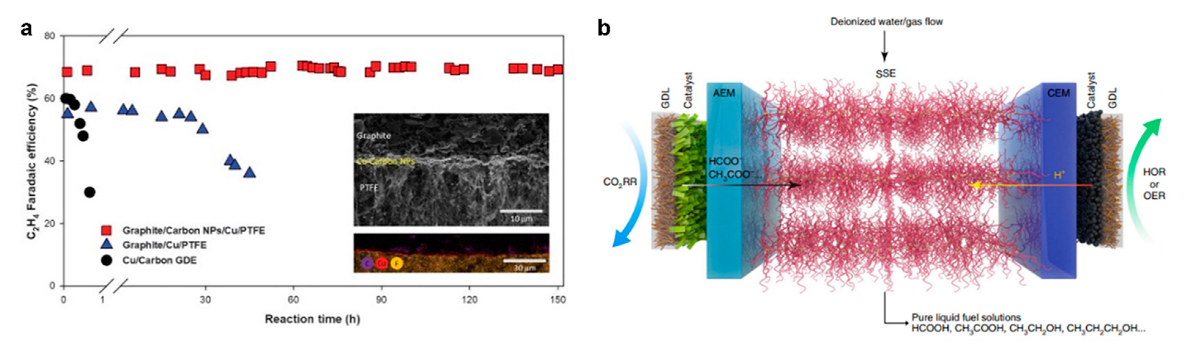
  45. Xia, C.; Zhu, P.; Jiang, Q.; Pan, Y.; Liang, W.; Stavitski, E.; Alshareef, H.N.; Wang, H. Continuous production of pure liquid fuel solutions via electrocatalytic CO2 reduction using solid-electrolyte devices. Nat. Energy 2019, 4, 776–785. [Google Scholar] [CrossRef]
  46. IRENA. Renewable Power Generation Costs in 2019; IRENA: Abu Dhabi, United Arab Emirates, 2020. [Google Scholar]
  47. Song, Y.; Zhang, X.; Xie, K.; Wang, G.; Bao, X. High-Temperature CO2 Electrolysis in Solid Oxide Electrolysis Cells: Developments, Challenges, and Prospects. Adv. Mater. 2019, 31, e1902033. [Google Scholar] [CrossRef]
  48. Mohammadi, A.; Mehrpooya, M. A comprehensive review on coupling different types of electrolyzer to renewable energy sources. Energy 2018, 158, 632–655. [Google Scholar] [CrossRef]
  49. Cheng, W.-H.; Richter, M.H.; Sullivan, I.; Larson, D.M.; Xiang, C.; Brunschwig, B.S.; Atwater, H.A. CO2 Reduction to CO with 19% Efficiency in a Solar-Driven Gas Diffusion Electrode Flow Cell under Outdoor Solar Illumination. ACS Energy Lett. 2020, 5, 470–476. [Google Scholar] [CrossRef] [Green Version]
  50. Chatterjee, S.; Griego, C.; Hart, J.L.; Li, Y.; Taheri, M.L.; Keith, J.A.; Snyder, J.D. Free Standing Nanoporous Palladium Alloys as CO Poisoning Tolerant Electrocatalysts for the Electrochemical Reduction of CO2 to Formate. ACS Catal. 2019, 9, 5290–5301. [Google Scholar] [CrossRef] [Green Version]
  51. Zhou, Y.; Zhou, R.; Zhu, X.; Han, N.; Song, B.; Liu, T.; Hu, G.; Li, Y.; Lu, J.; Li, Y. Mesoporous PdAg Nanospheres for Stable Electrochemical CO2 Reduction to Formate. Adv. Mater. 2020, 32, e2000992. [Google Scholar] [CrossRef]
  52. Pavesi, D.; Ali, F.S.M.; Anastasiadou, D.; Kallio, T.; Figueiredo, M.C.; Gruter, G.-J.M.; Koper, M.T.M.; Schouten, K.J.P. CO2 electroreduction on bimetallic Pd–In nanoparticles. Catal. Sci. Technol. 2020, 10, 4264–4270. [Google Scholar] [CrossRef]
  53. Weng, Z.; Zhang, X.; Wu, Y.; Huo, S.; Jiang, J.; Liu, W.; He, G.; Liang, Y.; Wang, H. Self-Cleaning Catalyst Electrodes for Stabilized CO2 Reduction to Hydrocarbons. Angew. Chem. Int. Ed. 2017, 56, 13135–13139. [Google Scholar] [CrossRef]
  54. Wang, Y.; Cao, L.; Libretto, N.J.; Li, X.; Li, C.; Wang, Y.; He, C.; Lee, J.; Gregg, J.; Zong, H.; et al. Ensemble Effect in Bimetallic Electrocatalysts for CO2 Reduction. J. Am. Chem. Soc. 2019, 141, 16635–16642. [Google Scholar] [CrossRef]
  55. Dutta, A.; Morstein, C.E.; Rahaman, M.; López, A.C.; Broekmann, P. Beyond Copper in CO2 Electrolysis: Effective Hydrocarbon Production on Silver-Nanofoam Catalysts. ACS Catal. 2018, 8, 8357–8368. [Google Scholar] [CrossRef]
  56. Akhade, S.A.; Luo, W.; Nie, X.; Bernstein, N.J.; Asthagiri, A.; Janik, M.J. Poisoning effect of adsorbed CO during CO2 electroreduction on late transition metals. Phys. Chem. Chem. Phys. 2014, 16, 20429–20435. [Google Scholar] [CrossRef]
  57. Koper, M.T.; Van Santen, R.R. Electric field effects on CO and NO adsorption at the Pt(111) surface. J. Electroanal. Chem. 1999, 476, 64–70. [Google Scholar] [CrossRef]
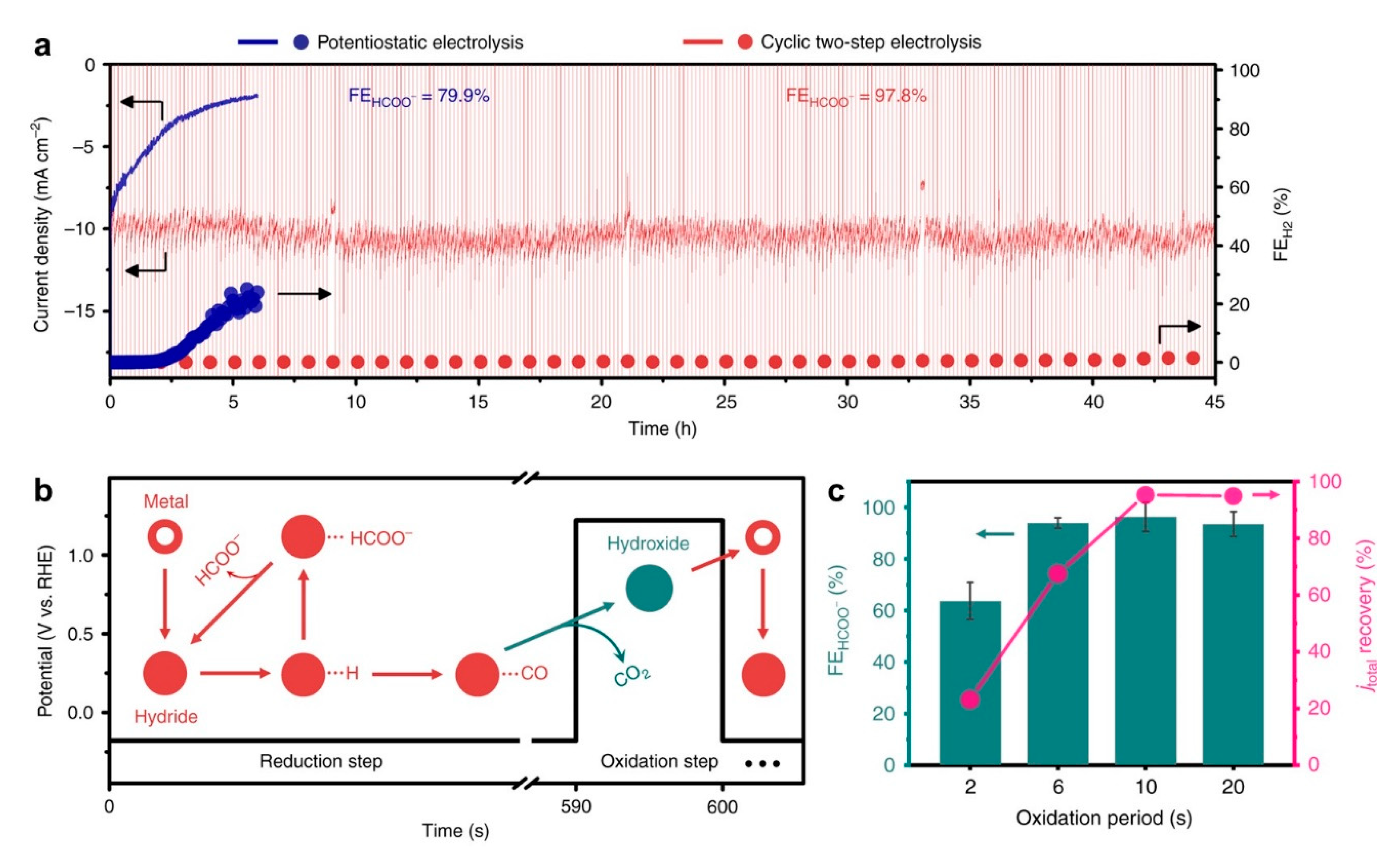
  58. Lee, C.W.; Cho, N.H.; Nam, K.T.; Hwang, Y.J.; Min, B.K. Cyclic two-step electrolysis for stable electrochemical conversion of carbon dioxide to formate. Nat. Commun. 2019, 10, 3919. [Google Scholar] [CrossRef] [Green Version]
  59. Jiang, S.; Klingan, K.; Pasquini, C.; Dau, H. New aspects of operando Raman spectroscopy applied to electrochemical CO2 reduction on Cu foams. J. Chem. Phys. 2019, 150, 041718. [Google Scholar] [CrossRef]
  60. Hori, Y.; Konishi, H.; Futamura, T.; Murata, A.; Koga, O.; Sakurai, H.; Oguma, K. “Deactivation of copper electrode” in electrochemical reduction of CO2. Electrochim. Acta 2005, 50, 5354–5369. [Google Scholar] [CrossRef]
  61. Lucas, F.W.S.; Lima, F.H.B. Electrodeposited Tin-Antimony Alloys as Novel Electrocatalysts for Selective and Stable Carbon Dioxide Reduction to Formate. ChemElectroChem 2020, 7, 3733–3742. [Google Scholar] [CrossRef]
  62. Lum, Y.; Kwon, Y.; Lobaccaro, P.; Chen, L.; Clark, E.L.; Bell, A.T.; Ager, J.W. Trace Levels of Copper in Carbon Materials Show Significant Electrochemical CO2 Reduction Activity. ACS Catal. 2016, 6, 202–209. [Google Scholar] [CrossRef] [Green Version]
  63. Bai, X.; Chen, W.; Zhao, C.; Li, S.; Song, Y.; Ge, R.; Wei, W.; Sun, Y. Exclusive Formation of Formic Acid from CO2 Electroreduction by a Tunable Pd-Sn Alloy. Angew. Chem. 2017, 129, 12387–12391. [Google Scholar] [CrossRef]
  64. Choi, W.; Won, D.H.; Hwang, Y.J. Catalyst design strategies for stable electrochemical CO2 reduction reaction. J. Mater. Chem. A 2020, 8, 15341–15357. [Google Scholar] [CrossRef]
  65. Won, D.H.; Shin, H.; Chung, M.W.; Jung, H.; Chae, K.H.; Oh, H.-S.; Hwang, Y.J.; Min, B.K. Achieving tolerant CO2 electro-reduction catalyst in real water matrix. Appl. Catal. B Environ. 2019, 258, 117961. [Google Scholar] [CrossRef] [Green Version]
  66. Yoo, C.J.; Dong, W.J.; Park, J.Y.; Lim, J.W.; Kim, S.; Choi, K.S.; Ngome, F.O.O.; Choi, S.-Y.; Lee, J.-L. Compositional and Geometrical Effects of Bimetallic Cu–Sn Catalysts on Selective Electrochemical CO2 Reduction to CO. ACS Appl. Energy Mater. 2020, 3, 4466–4473. [Google Scholar] [CrossRef]
  67. Alfath, M.; Lee, C.W. Recent Advances in the Catalyst Design and Mass Transport Control for the Electrochemical Reduction of Carbon Dioxide to Formate. Catalysts 2020, 10, 859. [Google Scholar] [CrossRef]
  68. Ouyang, R.; Liu, J.-X.; Li, W.-X. Atomistic Theory of Ostwald Ripening and Disintegration of Supported Metal Particles under Reaction Conditions. J. Am. Chem. Soc. 2013, 135, 1760–1771. [Google Scholar] [CrossRef]
  69. Zhang, A.; Liang, Y.; Li, H.; Zhang, B.; Liu, Z.; Chang, Q.; Zhang, H.; Zhu, C.-F.; Geng, Z.; Zhu, W.; et al. In-Situ Surface Reconstruction of InN Nanosheets for Efficient CO2 Electroreduction into Formate. Nano Lett. 2020, 20, 8229–8235. [Google Scholar] [CrossRef]
  70. Zhong, H.; Qiu, Y.; Li, X.; Pan, L.; Zhang, H. Ordered cone-structured tin directly grown on carbon paper as efficient electrocatalyst for CO2 electrochemical reduction to formate. J. Energy Chem. 2021, 55, 236–243. [Google Scholar] [CrossRef]
  71. Pan, F.; Yang, Y. Designing CO2 reduction electrode materials by morphology and interface engineering. Energy Environ. Sci. 2020, 13, 2275–2309. [Google Scholar] [CrossRef]
  72. Dutta, A.; Montiel, I.Z.; Erni, R.; Kiran, K.; Rahaman, M.; Drnec, J.; Broekmann, P. Activation of bimetallic AgCu foam electrocatalysts for ethanol formation from CO2 by selective Cu oxidation/reduction. Nano Energy 2020, 68, 104331. [Google Scholar] [CrossRef]
  73. Yang, H.; Huang, Y.; Deng, J.; Wu, Y.; Han, N.; Zha, C.; Li, L.; Li, Y. Selective electrocatalytic CO2 reduction enabled by SnO2 nanoclusters. J. Energy Chem. 2019, 37, 93–96. [Google Scholar] [CrossRef] [Green Version]
  74. Huang, J.; Hörmann, N.; Oveisi, E.; Loiudice, A.; De Gregorio, G.L.; Andreussi, O.; Marzari, N.; Buonsanti, R. Potential-induced nanoclustering of metallic catalysts during electrochemical CO2 reduction. Nat. Commun. 2018, 9, 3117. [Google Scholar] [CrossRef] [Green Version]
  75. Duan, Y.-X.; Meng, F.-L.; Liu, K.-H.; Yi, S.-S.; Li, S.-J.; Yan, J.-M.; Jiang, Q. Amorphizing of Cu Nanoparticles toward Highly Efficient and Robust Electrocatalyst for CO2 Reduction to Liquid Fuels with High Faradaic Efficiencies. Adv. Mater. 2018, 30, e1706194. [Google Scholar] [CrossRef] [PubMed]
  76. Matsubu, J.C.; Yang, V.N.; Christopher, P. Isolated Metal Active Site Concentration and Stability Control Catalytic CO2 Reduction Selectivity. J. Am. Chem. Soc. 2015, 137, 3076–3084. [Google Scholar] [CrossRef] [PubMed]
  77. Spoeri, C.; Kwan, J.T.H.; Bonakdarpour, A.; Wilkinson, D.P.; Strasser, P. The Stability Challenges of Oxygen Evolving Catalysts: Towards a Common Fundamental Understanding and Mitigation of Catalyst Degradation. Angew. Chem. Int. Ed. 2017, 56, 5994–6021. [Google Scholar] [CrossRef] [PubMed]
  78. De Luna, P.; Quintero-Bermudez, R.; Dinh, C.-T.; Ross, M.B.; Bushuyev, O.S.; Todorović, P.; Regier, T.; Kelley, S.O.; Yang, P.; Sargent, E.H. Catalyst electro-redeposition controls morphology and oxidation state for selective carbon dioxide reduction. Nat. Catal. 2018, 1, 103–110. [Google Scholar] [CrossRef] [Green Version]
  79. Andrews, E.M.; Flake, J.; Fang, Y. CO2 Electrocatalytic Reduction at Gold and Copper Electrodes: Role of Particle Size and Surface Chemistry. ECS Trans. 2015, 66, 67–70. [Google Scholar] [CrossRef]
  80. Kauffman, D.R.; Thakkar, J.; Siva, R.; Matranga, C.; Ohodnicki, P.R.; Zeng, C.; Jin, R. Efficient Electrochemical CO2 Conversion Powered by Renewable Energy. ACS Appl. Mater. Interfaces 2015, 7, 15626–15632. [Google Scholar] [CrossRef]
  81. Mistry, H.; Reske, R.; Zeng, Z.; Zhao, Z.-J.; Greeley, J.; Strasser, P.; Cuenya, B.R. Exceptional Size-Dependent Activity Enhancement in the Electroreduction of CO2 over Au Nanoparticles. J. Am. Chem. Soc. 2014, 136, 16473–16476. [Google Scholar] [CrossRef]
  82. Li, X.; Wang, S.; Li, L.; Sun, Y.; Xie, Y. Progress and Perspective for In Situ Studies of CO2 Reduction. J. Am. Chem. Soc. 2020, 142, 9567–9581. [Google Scholar] [CrossRef] [PubMed]
  83. Fiordaliso, E.M.; Sharafutdinov, I.; Carvalho, H.W.P.; Grunwaldt, J.-D.; Hansen, T.W.; Chorkendorff, I.; Wagner, J.B.; Damsgaard, C.D. Intermetallic GaPd2 Nanoparticles on SiO2 for Low-Pressure CO2 Hydrogenation to Methanol: Catalytic Performance and In Situ Characterization. ACS Catal. 2015, 5, 5827–5836. [Google Scholar] [CrossRef]
  84. Luc, W.; Collins, C.; Wang, S.; Xin, H.; He, K.; Kang, Y.; Jiao, F. Ag-Sn bimetallic catalyst with a core-shell structure for CO2 reduction. J. Am. Chem. Soc. 2017, 139, 1885–1893. [Google Scholar] [CrossRef] [PubMed]
  85. Mistry, H.; Varela, A.S.; Bonifacio, C.S.; Zegkinoglou, I.; Sinev, I.; Choi, Y.W.; Kisslinger, K.; Stach, E.A.; Yang, J.C.; Strasser, P.; et al. Highly selective plasma-activated copper catalysts for carbon dioxide reduction to ethylene. Nat. Commun. 2016, 7, 12123. [Google Scholar] [CrossRef]
  86. Gao, D.; Zegkinoglou, I.; Divins, N.J.; Scholten, F.; Sinev, I.; Grosse, P.; Cuenya, B.R. Plasma-Activated Copper Nanocube Catalysts for Efficient Carbon Dioxide Electroreduction to Hydrocarbons and Alcohols. ACS Nano 2017, 11, 4825–4831. [Google Scholar] [CrossRef] [PubMed]
  87. Armbrüster, M.; Schlögl, R.; Grin, Y. Intermetallic compounds in heterogeneous catalysis—A quickly developing field. Sci. Technol. Adv. Mater. 2014, 15, 034803. [Google Scholar] [CrossRef] [PubMed]
  88. Varela, A.S.; Schlaup, C.; Jovanov, Z.P.; Malacrida, P.; Horch, S.; Stephens, I.E.L.; Chorkendorff, I. CO2 Electroreduction on Well-Defined Bimetallic Surfaces: Cu Overlayers on Pt(111) and Pt(211). J. Phys. Chem. C 2013, 117, 20500–20508. [Google Scholar] [CrossRef]
  89. Jovanov, Z.P.; Hansen, H.A.; Varela, A.S.; Malacrida, P.; Peterson, A.A.; Nørskov, J.K.; Stephens, I.E.; Chorkendorff, I. Opportunities and challenges in the electrocatalysis of CO2 and CO reduction using bifunctional surfaces: A theoretical and experimental study of Au–Cd alloys. J. Catal. 2016, 343, 215–231. [Google Scholar] [CrossRef]
  90. Clark, E.L.; Hahn, C.; Jaramillo, T.F.; Bell, A.T. Electrochemical CO2 Reduction over Compressively Strained CuAg Surface Alloys with Enhanced Multi-Carbon Oxygenate Selectivity. J. Am. Chem. Soc. 2017, 139, 15848–15857. [Google Scholar] [CrossRef] [Green Version]
  91. Peterson, A.A.; Nørskov, J.K. Activity Descriptors for CO2 Electroreduction to Methane on Transition-Metal Catalysts. J. Phys. Chem. Lett. 2012, 3, 251–258. [Google Scholar] [CrossRef]
  92. Leonard, M.E.; Orella, M.J.; Aiello, N.; Román-Leshkov, Y.; Forner-Cuenca, A.; Brushett, F.R. Editors’ Choice—Flooded by Success: On the Role of Electrode Wettability in CO2 Electrolyzers that Generate Liquid Products. J. Electrochem. Soc. 2020, 167, 124521. [Google Scholar] [CrossRef]
  93. Leonard, M.E.; Clarke, L.E.; Forner-Cuenca, A.; Brown, S.M.; Brushett, F.R. Investigating Electrode Flooding in a Flowing Electrolyte, Gas-Fed Carbon Dioxide Electrolyzer. ChemSusChem 2020, 13, 400–411. [Google Scholar] [CrossRef]
  94. Dinh, C.-T.; Burdyny, T.; Kibria, G.; Seifitokaldani, A.; Gabardo, C.M.; De Arquer, F.P.G.; Kiani, A.; Edwards, J.P.; De Luna, P.; Bushuyev, O.S.; et al. CO2 electroreduction to ethylene via hydroxide-mediated copper catalysis at an abrupt interface. Science 2018, 360, 783–787. [Google Scholar] [CrossRef] [Green Version]
  95. Burchardt, T. An evaluation of electrocatalytic activity and stability for air electrodes. J. Power Sources 2004, 135, 192–197. [Google Scholar] [CrossRef]
  96. Bidault, F.; Brett, D.; Middleton, P.; Brandon, N. Review of gas diffusion cathodes for alkaline fuel cells. J. Power Sources 2009, 187, 39–48. [Google Scholar] [CrossRef]
  97. Jeanty, P.; Scherer, C.; Magori, E.; Wiesner-Fleischer, K.; Hinrichsen, O.; Fleischer, M. Upscaling and continuous operation of electrochemical CO2 to CO conversion in aqueous solutions on silver gas diffusion electrodes. J. CO2 Util. 2018, 24, 454–462. [Google Scholar] [CrossRef]
  98. Albo, J.; Perfecto-Irigaray, M.; Beobide, G.; Irabien, A. Cu/Bi metal-organic framework-based systems for an enhanced electrochemical transformation of CO2 to alcohols. J. CO2 Util. 2019, 33, 157–165. [Google Scholar] [CrossRef]
  99. Bienen, F.; Kopljar, D.; Löwe, A.; Geiger, S.; Wagner, N.; Klemm, E.; Friedrich, K.A. Revealing Mechanistic Processes in Gas-Diffusion Electrodes During CO2 Reduction via Impedance Spectroscopy. ACS Sustain. Chem. Eng. 2020, 8, 13759–13768. [Google Scholar] [CrossRef]
  100. Zhang, X.; Guo, S.-X.; Gandionco, K.A.; Bond, A.M.; Zhang, J. Electrocatalytic carbon dioxide reduction: From fundamental principles to catalyst design. Mater. Today Adv. 2020, 7, 100074. [Google Scholar] [CrossRef]
  101. Karamad, M.; Tripkovic, V.; Rossmeisl, J. Intermetallic Alloys as CO Electroreduction Catalysts—Role of Isolated Active Sites. ACS Catal. 2014, 4, 2268–2273. [Google Scholar] [CrossRef]
  102. Gu, J.; Hsu, C.-S.; Bai, L.; Chen, H.M.; Hu, X. Atomically dispersed Fe3+ sites catalyze efficient CO2 electroreduction to CO. Science 2019, 364, 1091–1094. [Google Scholar] [CrossRef] [PubMed]
  103. Bellini, M.; Folliero, M.G.; Evangelisti, C.; He, Q.; Hu, Y.; Pagliaro, M.V.; Oberhauser, W.; Marchionni, A.; Filippi, J.; Miller, H.A.; et al. A Gold–Palladium Nanoparticle Alloy Catalyst for CO Production from CO2 Electroreduction. Energy Technol. 2019, 7, 1800859. [Google Scholar] [CrossRef]
  104. Ma, X.; Li, Z.; Achenie, L.E.K.; Xin, H. Machine-Learning-Augmented Chemisorption Model for CO2 Electroreduction Catalyst Screening. J. Phys. Chem. Lett. 2015, 6, 3528–3533. [Google Scholar] [CrossRef]
  105. Zheng, X.; Ji, Y.; Tang, J.; Wang, J.; Liu, B.; Steinrück, H.-G.; Lim, K.; Li, Y.; Toney, M.F.; Chan, K.; et al. Theory-guided Sn/Cu alloying for efficient CO2 electroreduction at low overpotentials. Nat. Catal. 2019, 2, 55–61. [Google Scholar] [CrossRef]
  106. Bernal, M.; Bagger, A.; Scholten, F.; Sinev, I.; Bergmann, A.; Ahmadi, M.; Rossmeisl, J.; Cuenya, B.R. CO2 electroreduction on copper-cobalt nanoparticles: Size and composition effect. Nano Energy 2018, 53, 27–36. [Google Scholar] [CrossRef]
  107. Zhu, W.; Tackett, B.M.; Chen, J.G.; Jiao, F. Bimetallic Electrocatalysts for CO2 Reduction. Top. Curr. Chem. 2018, 376, 105–125. [Google Scholar] [CrossRef]
  108. Lee, S.Y.; Jung, H.; Kim, N.-K.; Oh, H.-S.; Min, B.K.; Hwang, Y.J. Mixed Copper States in Anodized Cu Electrocatalyst for Stable and Selective Ethylene Production from CO2 Reduction. J. Am. Chem. Soc. 2018, 140, 8681–8689. [Google Scholar] [CrossRef] [PubMed]
  109. Han, X.; Thoi, V.S. Non-Innocent Role of Porous Carbon Towards Enhancing C2-3 Products in Electroreduction of Carbon Dioxide. ACS Appl. Mater. Interfaces 2020, 12, 45929–45935. [Google Scholar] [CrossRef]
  110. Li, Q.; Zhang, X.; Zhou, X.; Li, Q.; Wang, H.; Yi, J.; Liu, Y.; Zhang, J. Simply and effectively electrodepositing Bi-MWCNT-COOH composite on Cu electrode for efficient electrocatalytic CO2 reduction to produce HCOOH. J. CO2 Util. 2020, 37, 106–112. [Google Scholar] [CrossRef]
  111. Liu, T.; Ali, S.; Lian, Z.; Li, B.; Su, D.S. CO2 electoreduction reaction on heteroatom-doped carbon cathode materials. J. Mater. Chem. A 2017, 5, 21596–21603. [Google Scholar] [CrossRef]
  112. Vasileff, A.; Zheng, Y.; Qiao, S.Z. Carbon Solving Carbon’s Problems: Recent Progress of Nanostructured Carbon-Based Catalysts for the Electrochemical Reduction of CO2. Adv. Energy Mater. 2017, 7, 1700759. [Google Scholar] [CrossRef]
  113. Klinkova, A.; De Luna, P.; Dinh, C.-T.; Voznyy, O.; Larin, E.M.; Kumacheva, E.; Sargent, E.H. Rational Design of Efficient Palladium Catalysts for Electroreduction of Carbon Dioxide to Formate. ACS Catal. 2016, 6, 8115–8120. [Google Scholar] [CrossRef]
  114. Malhotra, M.; Sharma, R.; Sanduja, M.; Kumar, R.; Jain, J.; Deep, A. Synthesis, characterization and evaluation of mannich bases as potent antifungal and hydrogen peroxide scavenging agents. Acta Pol. Pharm. Drug Res. 2012, 69, 355–361. [Google Scholar]
  115. Hegenberger, E.; Wu, N.L.; Phillips, J. Evidence of strong interaction between iron particles and an activated carbon support. J. Phys. Chem. 1987, 91, 5067–5071. [Google Scholar] [CrossRef]
  116. Sharma, S.; Pollet, B.G. Support materials for PEMFC and DMFC electrocatalysts—A review. J. Power Sources 2012, 208, 96–119. [Google Scholar] [CrossRef]
  117. Bittencourt, C.; Hecq, M.; Felten, A.; Pireaux, J.J.; Ghijsen, J.; Felicissimo, M.P.; Rudolf, P.; Drube, W.; Ke, X.; Van Tendeloo, G. Platinum-carbon nanotube interaction. Chem. Phys. Lett. 2008, 462, 260–264. [Google Scholar] [CrossRef] [Green Version]
  118. Yuan, J.; Yang, M.-P.; Zhi, W.-Y.; Wang, H.; Wang, H.; Lu, J.-X. Efficient electrochemical reduction of CO2 to ethanol on Cu nanoparticles decorated on N-doped graphene oxide catalysts. J. CO2 Util. 2019, 33, 452–460. [Google Scholar] [CrossRef]
  119. Liang, Z.-Q.; Zhuang, T.-T.; Seifitokaldani, A.; Li, J.; Huang, C.-W.; Tan, C.-S.; Li, Y.; De Luna, P.; Dinh, C.T.; Hu, Y.; et al. Copper-on-nitride enhances the stable electrosynthesis of multi-carbon products from CO2. Nat. Commun. 2018, 9, 3828. [Google Scholar] [CrossRef] [PubMed]
  120. Lewera, A.; Timperman, L.; Roguska, A.; Alonso-Vante, N. Metal–Support Interactions between Nanosized Pt and Metal Oxides (WO3 and TiO2) Studied Using X-ray Photoelectron Spectroscopy. J. Phys. Chem. C 2011, 115, 20153–20159. [Google Scholar] [CrossRef]
  121. Wen, G.; Ren, B.; Park, M.G.; Yang, J.; Dou, H.; Zhang, Z.; Deng, Y.; Bai, Z.; Yang, L.; Gostick, J.; et al. Ternary Sn-Ti-O Electrocatalyst Boosts the Stability and Energy Efficiency of CO2 Reduction. Angew. Chem. Int. Ed. 2020, 59, 12860–12867. [Google Scholar] [CrossRef]
  122. Pan, Y.; Lin, R.; Chen, Y.; Liu, S.; Zhu, W.; Cao, X.; Chen, W.; Wu, K.; Cheong, W.-C.; Wang, Y.; et al. Design of Single-Atom Co–N5 Catalytic Site: A Robust Electrocatalyst for CO2 Reduction with Nearly 100% CO Selectivity and Remarkable Stability. J. Am. Chem. Soc. 2018, 140, 4218–4221. [Google Scholar] [CrossRef] [PubMed]
  123. Jackson, M.N.; Oh, S.; Kaminsky, C.J.; Chu, S.B.; Zhang, G.; Miller, J.T.; Surendranath, Y. Strong Electronic Coupling of Molecular Sites to Graphitic Electrodes via Pyrazine Conjugation. J. Am. Chem. Soc. 2018, 140, 1004–1010. [Google Scholar] [CrossRef] [PubMed] [Green Version]
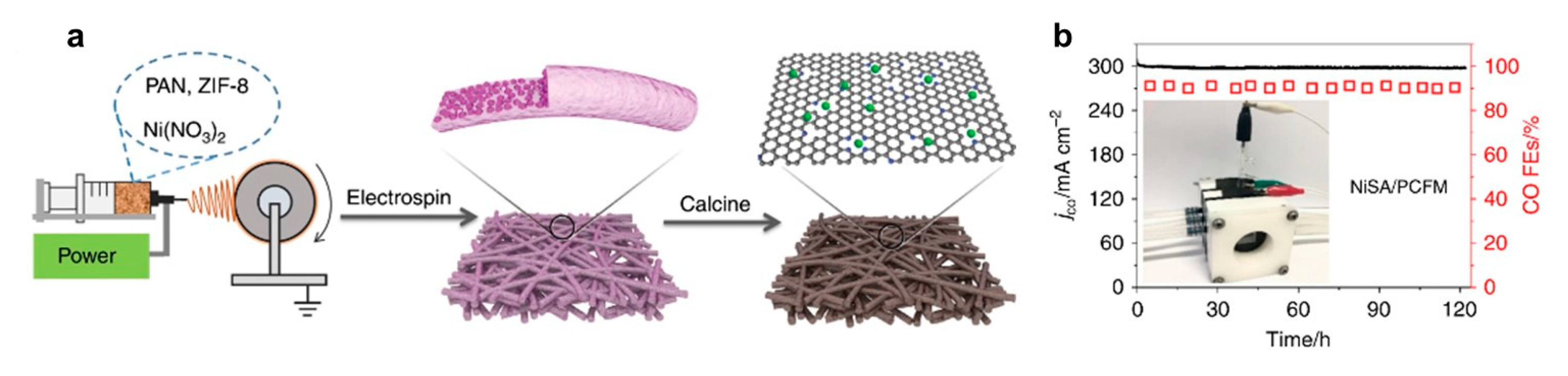
  124. Yang, H.; Lin, Q.; Zhang, C.; Yu, X.; Cheng, Z.; Li, G.; Hu, Q.; Ren, X.; Zhang, Q.; Liu, J.; et al. Carbon dioxide electroreduction on single-atom nickel decorated carbon membranes with industry compatible current densities. Nat. Commun. 2020, 11, 593. [Google Scholar] [CrossRef] [Green Version]
  125. Zhang, Y.-Y.; Li, J.-X.; Ding, L.-L.; Liu, L.; Wang, S.-M.; Han, Z.-B. Palladium Nanoparticles Encapsulated in the MIL-101-Catalyzed One-Pot Reaction of Alcohol Oxidation and Aldimine Condensation. Inorg. Chem. 2018, 57, 13586–13593. [Google Scholar] [CrossRef] [PubMed]
  126. Matsuda, S.; Tamura, S.; Yamanaka, S.; Niitsuma, Y.; Sone, Y.; Umeda, M. Minimization of Pt-electrocatalyst deactivation in CO2 reduction using a polymer electrolyte cell. React. Chem. Eng. 2020, 5, 1064–1070. [Google Scholar] [CrossRef]
  127. Lu, X.; Yu, T.; Wang, H.; Qian, L.; Lei, P. Electrochemical Fabrication and Reactivation of Nanoporous Gold with Abundant Surface Steps for CO2 Reduction. ACS Catal. 2020, 10, 8860–8869. [Google Scholar] [CrossRef]
  128. Hou, Y.; Bolat, S.; Bornet, A.; Romanyuk, Y.E.; Guo, H.; Moreno-García, P.; Montiel, I.Z.; Lai, Z.; Müller, U.; Grozovski, V.; et al. Photonic Curing: Activation and Stabilization of Metal Membrane Catalysts (MMCs) for the Electrochemical Reduction of CO2. ACS Catal. 2019, 9, 9518–9529. [Google Scholar] [CrossRef]
Figure 1. Sensitivity analysis of end-of-life net present value (NPV) for CO2-reduction products: (a) n-propanol, (b) carbon monoxide, (c) ethylene, and (d) formic acid. Adapted from Jouny et al. Reprinted with permission from ref. [9]. Copyright 2018, ACS.
Catalysts 11 00253 g001
Figure 2. The bipolar membranes (BPM) configuration with base (1 M NaOH) in the anion exchange layer (AEL) as the anode and acid (1 M HClO4) in the cation exchange layer (CEL) as the cathode. Thus, OH is consumed at the anode and H+ is consumed at the cathode; Na+ and ClO4 transport is electrostatically attenuated, and the ionic current is enabled by water dissociation in the interfacial layer. Reproduced with permission from ref. [32]. Copyright 2014, Wiley-VCH.
Catalysts 11 00253 g002
Figure 3. The performance characteristics of the dual electrolyte microfluidic reactor (DEMR): (a) current densities at an applied voltage of 2.8 V before and after electrolyte optimizations; (b) cathode potentials at 100 mA/cm2 and catholyte pH values of 7, 1 and 0, and anode potentials at 150 mA/cm2 and anolyte pH values of 7, 13 and 14; (c) peak Faradaic and energy efficiencies before and after electrolyte optimization. Reproduced with permission from ref. [37]. Copyright 2016, Elsevier.
Catalysts 11 00253 g003
Figure 4. Schematic diagrams of the flow field patterns in the two types of zero-gap electrolyzer: (A) the parallel pattern, in, which mass transfer is due to diffusion, and (B) the interdigitated pattern, in, which mass transfer is a combination of diffusion and convection. Reproduced with permission from ref. [43]. Copyright 2020, Wiley-VCH.
Catalysts 11 00253 g004
Figure 5. Schematic illustration of the all-solid-state electrochemical CO2 to formic acid reactor: EM = anion exchange membrane, CEM = cation exchange membrane, GDL = gas diffusion layer, PSE = porous solid electrolyte. Electrochemically generated HCOO and H+ ions are driven by the electric field to move across the EM or CEM into the PSE layer, where they recombine to form the formic acid molecule. This can then be released quickly in the vapor phase via the N2 carrier gas flow. Reproduced with permission from ref. [29] Copyright 2020, Springer Nature.
Catalysts 11 00253 g005
Figure 6. The global weighted average levelized cost of electricity (LCOE) from utility-scale renewable power generation technologies between 2010 and 2019. Reproduced with permission from ref. [46]. Copyright © IRENA 2020.
Catalysts 11 00253 g006
Figure 7. The superstructure of the electrochemical coproduction process is used to simultaneously consider all possible structures of the process. Reproduced with permission from ref. [7], copyright 2019, Springer Nature.
Catalysts 11 00253 g007
Figure 8. A techno-economic analysis of carbon monoxide and formic acid production via the electrochemical CO2-reduction process throughout the catalyst’s operative life under different scenarios. The process models and parameters of analysis are based on Na et al. [7].
Catalysts 11 00253 g008
Figure 9. Catalyst deactivation mechanism by poisoning: (a) schematic diagrams showing carbon accumulation on a copper catalyst surface; (b) the calculated C/Cu ratios on the catalyst surface after electrochemical carbon dioxide reduction reaction (CO2RR) for various times; (c) bar chart indicating the types and relative abundances of carbonaceous bond observed on the catalyst surface after electrochemical CO2RR (reproduced with permission from ref. [53], copyright 2017, WILEY-VCH); (d) schematic illustration of the CO poisoning of a Pd electrocatalyst due to the strong binding (large desorption energy barrier) of CO (reproduced with permission from ref. [54], copyright 2019, ACS).
Catalysts 11 00253 g009
Figure 10. Catalyst restructuring: (a) schematic restructuring mechanism of the CuNC catalyst during the CO2RR, including nanoclustering (stage I) followed by coalescence (stage II) (reproduced with permission from ref. [74], copyright 2018, Springer Nature); (b,c) SEM images of the same location on an Ag-foam catalyst (b) before, and (c) after the electrochemical CO2RR at −1.5 V vs. RHE, showing restructuring of the catalyst (reproduced with permission from ref. [55], copyright 2018, ACS).
Catalysts 11 00253 g010
Figure 11. The effects of using a redox shuttle (i.e., an electrolyte additive capable of reversible oxidative-reductive reaction at a specific potential): (a) the potential dependence of the CO2RR product selectivity of the CuOx catalyst in 0.5 M CO2-saturated KHCO3 when using a redox shuttle. The error bars represent the standard deviation based on three individual measurements; (b) the time-resolved variations in the Cu species in CuOx and the corresponding electrochemical responses during the CO2RR at −0.75 V when using a redox shuttle; (c) for comparison, the time-resolved variations in the Cu species in CuOx and the corresponding electrochemical responses during the CO2RR at −0.75 V, obtained using chronoamperometry (reproduced with permission from ref. [6], copyright 2020, Springer Nature).
Catalysts 11 00253 g011
Figure 12. Degradation of the gas diffusion layers (GDL): (a) a schematic diagram showing the process of electrode flooding during electrochemical CO2 reduction; (b) the effects of current density upon GDL degradation; (c) a visualization of GDL degradation at different applied current densities (reproduced with permission from ref. [93], copyright 2020, WILEY VCH).
Catalysts 11 00253 g012
Figure 13. The influence of alloying and the presence of a co-adsorbent upon catalyst deactivation by CO: (a) the tabulated binding energies (in eV) of CO to a clean surface (CO*-1), a surface with co-adsorbed H* (CO*-2), and a surface with 2H* (CO*-3), along with the binding of H to a clean surface (H*-1), a surface with H* (H*-2), and a surface with CO* (H*-3) (reproduced with permission from ref. [50], copyright 2019, ACS); (b) linear sweep voltammetry of Pd and PdAg_2 immediately after application of a −0.27 V bias for 1 h in CO2-saturated 0.1 M KHCO3 (reproduced with permission from ref. [51], copyright 2020, Wiley-VCH).
Catalysts 11 00253 g013
Figure 14. The effects of various support materials for a Cu catalyst: (a) in situ Cu K-edge spectra obtained during the initial 30 min for the supported catalysts Cu-on-Cu3N (green) and Cu-on-Cu2O (orange), along with reference spectra for Cu (red) and Cu3N (yellow); (b) the ratio of Cu+ to reaction time at −0.95 V vs. RHE; (c) the stability of Cu, Cu-on-Cu2O, and Cu-on-Cu3N towards C2+ selectivity (reprinted with permission from ref. [119], copyright 2018, Springer Nature).
Catalysts 11 00253 g014
Figure 15. A robust Ni single atom supported on porous carbon fibers membrane (NiSA/PCFM): (a) schematic synthesis; (b) the results of current density (black line) and FE (red squares) for CO production long-term stability tests in a GDL-based flow cell at −1.0 VRHE (reproduced with permission from ref. [124], copyright 2020, Springer Nature).
Catalysts 11 00253 g015
Figure 16. (a) Comparison of the cyclic two-step electrolysis and potentiostatic electrolysis in terms of current density and product selectivity; (b) potential program and reaction scheme for the cyclic two-step electrolysis; (c) the dependence of the current density recovery (jtotal) and the HCOO FE on the oxidation period (reproduced with permission from ref. [58], copyright 2019, Springer Nature).
Catalysts 11 00253 g016
Figure 17. (a) A comparison of the selectivity towards CO2 reduction to ethylene in 7 M KOH and the stability of a graphite/carbon NPs/Cu/PTFE electrode and a traditional carbon-based GDE. The insets show the cross-sectional SEM and energy-dispersive X-ray spectroscopy mapping of the sample after 150 h of continuous operation (reproduced with permission from ref. [94], copyright 2018, AAAS); (b) a schematic illustration of a CO2 reduction cell with a solid electrolyte. The SSE is either an anion or cation conductor (reproduced with permission from ref. [45], copyright 2019, Springer Nature).
Catalysts 11 00253 g017
Publisher’s Note: MDPI stays neutral with regard to jurisdictional claims in published maps and institutional affiliations.

