Article

Mesoporous Composite Networks of Linked MnFe2O4 and ZnFe2O4 Nanoparticles as Efficient Photocatalysts for the Reduction of Cr(VI)

by
Euaggelia Skliri
1,
Ioannis Vamvasakis
1,
Ioannis T. Papadas
2,
Stelios A. Choulis
2 and
Gerasimos S. Armatas
1,*
1
Department of Materials Science and Technology, University of Crete, 70013 Heraklion, Greece
2
Department of Mechanical Engineering and Materials Science and Engineering, Cyprus University of Technology, Limassol 3041, Cyprus
*
Author to whom correspondence should be addressed.
Catalysts 2021, 11(2), 199; https://doi.org/10.3390/catal11020199
Submission received: 28 December 2020 / Revised: 20 January 2021 / Accepted: 28 January 2021 / Published: 4 February 2021

Abstract

:
Semiconductor photocatalysis has recently emerged as an effective and eco-friendly approach that could meet the stringent requirements for sustainable environmental remediation. To this end, the fabrication of novel photocatalysts with unique electrochemical properties and high catalytic efficiency is of utmost importance and requires adequate attention. In this work, dual component mesoporous frameworks of spinel ferrite ZnFe2O4 (ZFO) and MnFe2O4 (MFO) nanoparticles are reported as efficient photocatalysts for detoxification of hexavalent chromium (Cr(VI)) and organic pollutants. The as-prepared materials, which are synthesized via a polymer-templated aggregating self-assembly method, consist of a continuous network of linked nanoparticles (ca. 6–7 nm) and exhibit large surface area (up to 91 m2 g−1) arising from interstitial voids between the nanoparticles, according to electron microscopy and N2 physisorption measurements. By tuning the composition, MFO-ZFO composite catalyst containing 6 wt.% MFO attains excellent photocatalytic Cr(VI) reduction activity in the presence of phenol. In-depth studies with UV-visible absorption, electrochemical and photoelectrochemical measurements show that the performance enhancement of this catalyst predominantly arises from the suitable band edge positions of constituent nanoparticles that efficiently separates and transports the charge carriers through the interface of the ZFO/MFO junctions. Besides, the open pore structure and large surface area of these ensembled networks also boost the reaction kinetics. The remarkable activity and durability of the MFO-ZFO heterostructures implies the great possibility of implementing these new nanocomposite catalysts into a realistic Cr(VI) detoxification of contaminated wastewater.

Graphical Abstract

1. Introduction

The rapid development of civilization and industrial activities has led to a large number of pollutants being disposed into the environment either intentionally or accidentally [1]. Hexavalent chromium (Cr(VI)) is a highly toxic and non-biodegradable pollutant that is discarded in water resources as a by-product of many industrial processes, like leather tanning, electroplating, metal finishing, and others [2,3,4]. Compared to trivalent chromium (Cr(III)), Cr(VI) oxyanions are far more toxic and mobile, and therefore, difficult to remove from water. The World Health Organization (WHO) recommended a maximum allowable concentration of 50 μg L−1 for Cr in drinking water [5]. Moreover, as a consequence of its high toxicity, Cr(VI) has also been classified as a group I human carcinogen by the International Agency for Research on Cancer (IARC) [6]. Therefore, finding effective ways for detoxification of Cr(VI)-contaminated solutions is undoubted of high priority in the field of environmental and health protection.
Over the past years, a variety of techniques has emerged for remediation of Cr(VI) from aqueous solutions and industrial effluents, among them chemical precipitation [7], adsorption [8], ion exchange [9], reverse osmosis, and more recently chemical reduction with organic reducing substances or sulfate-based materials [10,11]. However, the effectiveness of these techniques is accompanied by high capital and operation cost as well as complex purification steps; for example, they need a large quantity of chemicals and usually generate secondary wastes as by-products [10]. Recently, semiconductor photocatalysis has been considered a viable and eco-friendly approach for the degradation of environmental pollutants. In this context, various semiconductor materials, such as TiO2 [12], SnS2 [13], ZnO [14], Bi2O3 [15], and CoO [16,17], have been applied to UV or visible light-induced photocatalytic reduction of toxic Cr(VI) to less harmful Cr(III). Unlike Cr(VI), aqueous Cr(III) can be easily precipitated as Cr(OH)3 or Cr2O3 solids in alkaline solutions [18,19]. Although many of these catalysts demonstrated remarkable Cr(VI) photoreduction activity with good ability for wastewater remediation, their poor electron–hole separation, low solar light absorption, and limited structural stability are still important challenges to be overcome. In addition to heavy metals, wastewaters frequently contain recalcitrant dyes, pesticides, and phenolic contaminants that may increase the difficulty of pollutant abatement [20]. In such photocatalytic systems, the organic substances may compete with Cr(VI) ions for absorption on the catalyst surface, resulting in the activity decrease for Cr(VI) reduction. The absorbed organic compounds may block some of the surface-active sites of the catalyst and inhibit light absorption. Therefore, the simultaneous redox degradation of Cr(VI) and organic contaminants is an interesting task.
Zinc ferrite (ZnFe2O4, ZFO) is a kind of spinel-type oxide which possesses low cost, visible light responsiveness (it has a band gap of around 1.9–2.1 eV), and excellent photochemical stability [21,22,23]. Consequently, ZnFe2O4 based materials have been investigated as photocatalysts for photo-Fenton-like degradation of organic dyes [24,25,26], and photochemical hydrogen production [27,28]. Also, manganese spinel ferrite (MnFe2O4, MFO) with good magnetic responsivity and functional surface has been widely used as an adsorbent for removing heavy metals from water [29]. Recently, we reported the synthesis of mesoporous assemblies of spinel ferrite MFe2O4 (M = Zn2+, Mn2+, Ni2+, Cd2+, and Co2+) nanoparticles (NPs) and demonstrated their functionality as catalysts in the reductive remediation of Cr(VI)-contaminated solution [30]. These materials exhibited very good Cr(VI) photoreduction performance and stability, due to their unique open porous structure and improved charge transfer along with the NP-linked framework. In this study, we present the first demonstration of chemically stable and robust mesoporous MFO/ZFO composite networks as effective photocatalysts for the detoxification of Cr(VI)-containing wastewaters under UV-visible light irradiation. We use a block copolymer-templated cross-linking aggregation of colloidal NPs to assemble dual component MFO-ZFO NP linked networks with different MFO content (i.e., 4, 6, 8, and 12 wt.%). Characterization with X-ray diffraction, high-resolution transmission electron microscopy, and N2 porosimetry confirmed a highly porous structure consisting of connected small-sized (ca. 6–7 nm) spinel ferrite nanoparticles. Mechanistic studies with UV-visible optical absorption, electrochemical and photoelectrochemical measurements indicated that the enhanced reactivity of this catalytic system arises from the suitable band edge positions of constituent NPs which promotes the efficient separation and transport of photogenerated charges at the ZFO/MFO junctions. Finally, a plausible mechanistic scheme for the photocatalytic reduction of Cr(VI) over MFO-ZFO composite catalysts is proposed based on the experimental results.

2. Results and Discussion

2.1. Structure and Morphology of MFO-ZFO MNAs

Mesoporous assemblies from MnFe2O4 (MFO) and ZnFe2O4 (ZFO) spinel ferrite NPs were prepared by cross-linking polymerization of NP colloids in the presence of a block copolymer template. Briefly, the co-assembly of ZFO and MFO NPs with polymer template (Pluronic P123, BASF) occurs via a solvent evaporation-induced aggregating self-assembly process, in which slow evaporation of solvent promotes the arrangement of NPs into mesostructured NP/polymer composites [31]. The NP/polymer composites were then calcined at 350 °C in the air to give a continuous network of assembled NPs with an open pore structure. By tuning the ratio of the ZFO and MFO precursor NPs, we succeeded in preparing a series of samples with different compositions. The obtained materials are denoted as MFO-n-ZFO mesoporous nanoparticle assemblies (MNAs), where n refers to the weight percent of the MFO component, i.e., n = 4, 6, 8, and 12 wt.%. The crystallinity and phase purity of the resultant materials were determined by X-ray diffraction (XRD) measurements. Figure 1a shows the XRD patterns of the single-component ZFO and MFO MNAs and composite MFO-ZFO MNAs samples, where all the reflection peaks can be assigned to the spinel structure of metal ferrites (ZFO and MFO). Analysis of the (311) reflection with the Scherrer equation gives an average grain size of ~6.2–6.8 nm, which is very close to the size of starting NPs (ca. 6–7 nm) [30], see Table 1. This suggests that the size changes of the crystallites are limited after thermal annealing. Notably, no impurities (like MnxOy, ZnO, or other metal oxide phases) were evident in the XRD patterns, suggesting the phase purity of the samples.
The morphology and microstructure of the assembled materials were observed by transmission electron microscopy (TEM), and typical results for the MFO-6-ZFO MNAs, which is the most active catalyst of this work, are shown in Figure 1b,c. The images reveal that the sample consists of a porous network of aggregated small NPs. As shown in the high-resolution TEM (HRTEM) image in Figure 1c, the constituent NPs have an average diameter of around 6–7 nm, in agreement with XRD results, and are interlinked to a continuous structure. The direct NP-to-NP contact is advantageous to photocatalytic processes, since it efficiently transports and separates the photogenerated charge carriers within the assembled structure. HRTEM also gave further information on the single-crystalline nature of the constituent NPs, showing well-defined lattice fringes throughout the particles. The lattice fringes of 2.1 Å and 4.9 Å spacing in the NPs are indexed to the (004) and (111) crystal plane of spinel ferrite structure, respectively. Consistent with XRD and HRTEM analyses, the spinel structure of assembled NPs was evidenced by selected area electron diffraction (SAED) analysis. The SAED pattern in Figure 1d shows a series of diffuse Debye-Scherrer rings that can be readily assigned to the spinel ferrite phase of ZFO and MFO.
The porosity of the as-prepared materials was probed with N2 physisorption measurements. Figure 2 shows N2 adsorption–desorption isotherms and the corresponding pore size distribution plots for the MFO-ZFO MNAs. The corresponding plots for the ZFO and MFO MNAs are given in Figure S1. All the isotherms show typical type-IV curves, according to the IUPAC classification, with a distinct H3-type hysteresis loop, being characteristic of porous solids with slit-like mesopores. The specific surface areas and total pore volumes of the composite materials were measured to be 68–91 m2 g−1 and 0.09–0.14 cm3 g−1, respectively, which are slightly lower than the surface area and pore volume of single component ZFO and MFO MNAs (105–106 m2 g−1, 0.15–0.21 cm3 g−1, see Figure S1). The pore size in these materials was derived from the adsorption branch of isotherms using the NLDFT method (based on slit-like pores). The NLDFT analysis indicated quite narrow size distributions of pores with an average pore diameter of ~5 to 6 nm (insets of Figure 2 and Figure S1). Table 1 summarizes the textural parameters of the prepared catalyst.

2.2. Photocatalytic Study of MFO-ZFO MNAs

The photocatalytic Cr(VI) reduction activity of the title materials was initially assessed in the presence of phenol (400 mg L−1) as coexistent pollutant. Figure 3a displays the temporal concentration changes (Ct/Co) of Cr(VI) during the photocatalytic process with different catalysts, namely, ZFO, MFO, and MFO-ZFO MNAs. All the catalytic reactions were performed at the same dose of catalyst (500 mg L−1) dispersed in a Cr(VI) contaminated water (50 mg L−1), under λ > 360 nm light irradiation. The comparison shows that the integration of MFO with the ZFO NPs has a profound effect on the Cr(VI) photoreduction performance. As shown in Figure 3a, MFO-6-ZFO exhibits the highest reactivity among the samples, achieving an almost complete (>99%) reduction of the Cr(VI) in 3 h. Under identical conditions, the 4, 8, and 12 wt.% MFO loaded samples reduce the Cr(VI) by ~70%, ~94%, and ~83%, respectively, while the single component MFO and ZFO MNAs reduce ~90% and ~88% of Cr(VI). Control experiments in the absence of catalyst or light irradiation showed almost no changes in the initial concentration of Cr(VI) (see Figure 3a), confirming that the reduction of Cr(VI) originated from the photoredox reactions on the catalyst under light illumination. Assuming that the reaction rate is proportional to the concentration of Cr(VI), the photocatalytic reaction can be expressed by the pseudo-first-order kinetics of the Langmuir–Hinshelwood model (Equation (1)).
Ln(Ct/Co) = −kapp × t
where, Co and Ct are the initial and at time t concentration of Cr(VI), respectively, and kapp is the apparent reaction rate constant.
Thus, analysis of the temporal evolution of Cr(VI) concentration using Equation (1) reveals a rate constant kapp of 3.6 × 10⁻³ and 5.3 × 10⁻³ min−1 for ZFO and MFO MNAs, respectively, and in the range of 4.3–14.4 × 10⁻³ min−1 for dual component MFO-ZFO assemblies. The ln(Ct/Co) versus time plots for different catalysts are shown in Figure S2. As shown in Figure 3b, the MFO-6-ZFO MNAs outperform the other catalysts, yielding faster reaction kinetics with kapp value of 14.41 × 10⁻³ min−1, which is about 4 and 2.7 times higher than the kapp value obtained for the ZFO and MFO MNAs, respectively. We suggest that the high reactivity of MFO-6-ZFO is related to the open pore structure, which facilitates fast molecular diffusion, and the suitable electronic band structure of constituent NPs, which efficiently separates and transports the photogenerated electron-hole pairs (see below). Accordingly, we focused on Cr(VI) reduction reactions with this catalyst in our further studies.
Figure 3c shows comparative results of the Cr(VI) photoreduction over MFO-6-ZFO composite in the absence and presence of phenol (three equiv. compared to Cr(VI)). It can be observed that, without phenol, the Cr(VI) photoreduction proceeds, but at a lower reaction rate; MFO-6-ZFO MNAs show a ~25% Cr(VI) conversion in 2 h in pure water. Unlike oxidation of phenol, the photo-oxidation of water to dioxygen is a sluggish reaction that involves several uphill, multi-electron reaction steps, such as dissociation of –OH species and formation of O–O bonds. In a previous study, we showed that water oxidation to molecular oxygen over ZFO NP assemblies is a viable process [30]. Therefore, phenol enables more efficient utilization of the surface-reaching holes, leading to a significant improvement of the photo-oxidation efficiency. This study clearly suggests that the photocatalytic reduction of Cr(VI) and oxidation of phenol are collaborative over the mesoporous MFO-ZFO assemblies, and this process can enhance the photoreduction effect. To explore the possibility of MFO-6-ZFO MNAs in practical application, the Cr(VI) photoreduction activity of MFO-6-ZFO MNAs was examined in the presence of other pollutants, such as citric acid (CA) and ethylenediaminetetraacetic acid (EDTA). All these experiments were made by using the same dose of catalyst (0.5 g L−1) in 50 mL of Cr(VI) aqueous solution (50 mg L−1) containing three equiv. of organic pollutants that represent typical concentrations in industrial wastewaters [32,33]. The results showed that the Cr(VI) photoreduction in the presence of citric acid and EDTA is much faster than with phenol (Figure 3c); the photocatalytic reaction with citric acid and EDTA was complete within only ~15–20 min. Meanwhile, control experiments showed that the Cr(VI) reduction did not proceed in the dark, again confirming that this reaction is photocatalytic in nature (Figure 3c).The observed increased Cr(VI) reduction rate can be attributed to the fact that, compared to phenol, citric acid and EDTA can consume the photogenerated holes more effectively because of their favorable adsorption on the surface of catalyst, preventing multiple holes accumulation, and thus, electron-hole recombination at the MFO-ZFO surface. In particular, under acidic conditions (pH ~2), there are electrostatic attractions between the positively charged ≡M–OH2+ catalyst surface and negatively charged EDTA (in the form of H3EDTA (pKa1 = 1.99) and H2EDTA2− (pKa2 = 2.67)) and citric acid (in the form of H2CA pKa1 = 3.1) ions, which result in an increased concentration of these species near the catalyst’s surface [34]. On the contrary, in these reaction conditions, phenol predominately exists in its neutral molecular form (it has a pKa of about 9.88), which is absorbed by the catalyst through weak van der Waals and hydrogen bonds.
In addition to chemical composition, morphological effects may also contribute to the photocatalytic activity of MFO-6-ZFO MNAs. To elucidate this possibility, we prepared random aggregates of MFO and ZFO NPs (denoted as MFO-6-ZFO RNAs) following a similar procedure as being used for the MFO-6-ZFO MNAs, but without a template. These two samples feature with ZFO and MFO NPs linked into a network structure (the weight content of MFO is ca. 6%), but with different porosity. We obtained an N2 adsorption-desorption isotherm that is a type-II curve with an H3 hysteresis loop for the MFO-6-ZFO RNAs, which is characteristic of nanoporous solids with slit-shaped pores (Figure S3). Analysis of the adsorption data indicated a surface area of 50 m2 g−1 and a pore size of 2.9 nm. The catalytic results presented in Figure 3a show that the photocatalytic Cr(VI) reduction efficiency of the randomly aggregated NPs (MFO-6-ZFO RNAs) is significantly lower than that of polymer-templated analogs, giving a respective Cr(III) conversion yield of ~54% in 3 h. Furthermore, pseudo-first-order analysis of Cr(VI) photoreduction also reveals that the reaction proceeds at a lesser rate over the random aggregates MFO-6-ZFO RNAs (kapp = 3.05 × 10⁻³ min−1) than the mesoporous MFO-6-ZFO MNAs (kapp = 14.41 × 10⁻³ min−1), see Figure S4. The variance in catalytic activity between MFO-6-ZFO RNAs and MFO-6-ZFO MNAs should be ascribed to their different pore structures. The untemplated material contains a random distribution of interstitial pores between the NPs (ca. 2.9 nm, according to N2 physisorption data), which may result in slow transport kinetics of Cr(VI) ions.
The reusability of the MFO-6-ZFO MNAs catalyst was investigated by conducting three recycling experiments in the presence of 50 mg L−1 Cr(VI) and 400 mg L−1 phenol. The catalyst was isolated by centrifugation after completion of the reaction, washed with water, and placed in a fresh Cr(VI)/phenol solution. As seen in Figure 3d, MFO-6-ZFO MNAs catalyst retains its initial activity after at least three 3-h recycling tests. Moreover, XRD and N2 porosimetry data confirmed that the crystal and porous structure of the reused catalyst are well maintained after photocatalysis, indicating high durability, see Figure S5.

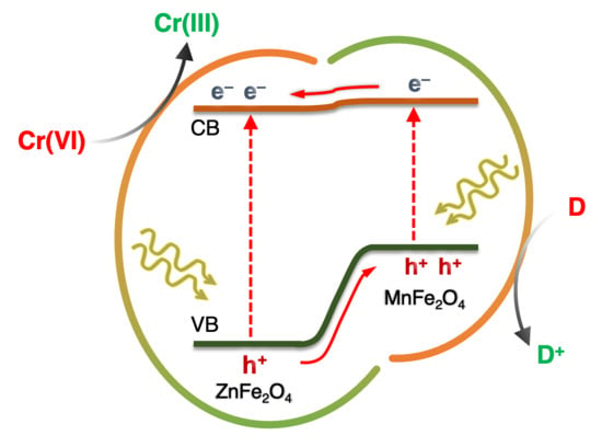
2.3. Mechanism of Photocatalytic Cr(VI) Reduction

To help explain the relationship between photochemical activity and electronic band structure, we investigated the electronic structure of as-prepared catalysts by combining electrochemical impedance (EIS) and optical absorption spectroscopy. Figure 4a and Figure S6a display the Mott–Schottky plots recorded at a frequency of 1 kHz and the corresponding linear fits on the inverse square capacitance (1/Csc2) versus applied potential (E) data for the mesoporous ZFO, MFO, and MFO-ZFO catalysts. Using extrapolation to 1/Csc2 = 0, the flat band potential (EFB) for MFO-ZFO MNAs is seen to be located at −0.19 V to −0.33 V versus NHE, while the EFB position of ZFO and MFO MNAs locates at −0.17 V and −0.31 V, respectively (see Table 2). Obviously, the EFB level of the composite materials undergoes a cathodic shift upon incorporating MFO NPs into the ZFO assembled structure, which is consistent with the more negative EFB potential of MFO. The electron donor density (Nd) obtained from the slope of 1/Csc2 versus E curves ranges between 9.71 × 10¹⁵ and 1.88 × 1017 cm−3 for MFO-ZFO MNAs and appears around 3.63 × 10¹⁶ and 1.12 × 1017 cm−3 for ZFO and MFO MNAs, respectively (Table 2). It is apparent that all the Mott–Schottky plots show a positive linear slope, indicating n-type conductivity. The optical band gap (Eg) of the prepared materials was determined from UV-vis/NIR diffuse reflectance spectra, using Tauc plot analysis for direct band gap semiconductor (i.e., (αhv)2 versus energy (hv) plots), as shown in Figure 4b and Figure S6b. This analysis yields Eg values of 2.17 eV and 1.46 eV for ZFO and MFO MNAs, respectively, and from 2.13 to 2.16 eV for MFO-ZFO MNAs samples. Table 2 summarizes the results of electrochemical and optical absorption characteristics of ZFO, MFO, and MFO-ZFO catalysts.
Based on the measured EFB potentials and optical band gaps, the energy band diagram for each catalyst can be obtained and is illustrated in Figure 5. Here, we assumed that the EFB level is located very close to the CB edge of the catalysts, which is quite reasonable for heavily doped n-type semiconductors, such as ZnFe2O4; typically, the EFB potential is about 0.1–0.3 V lower than the CB edge level [35]. Therefore, the valence band potential (EVB) of the catalysts can be obtained by the difference between EFB and Eg. From these results, it is clear that the CB edge of the MFO-ZFO MNAs is aligned well above the redox potential of Cr(VI)/Cr(III), thus demonstrating the ability of these materials for multi-electron reduction of Cr(VI) to Cr(III) under irradiation. Meanwhile, all the catalysts meet the electrochemical requirement for the oxidation of organic pollutants (such as phenol); that is, the VB position in these materials is below (more positive) the oxidation potential of phenol. The high photocatalytic activity obtained with the MFO-6-ZFO MNAs can be explained by the favorable alignment of band edges relative to the reduction potential of Cr(VI) and oxidation potential of organic pollutants. Namely, MFO-6-ZFO MNAs have a relatively high EFB potential (−0.33 V), which reflects a better reducing ability of CB electrons, and a sufficiently deep VB potential (1.83 V), which favors the oxidation of organic pollutants (e.g., phenol). Moreover, MFO-6-ZFO MNAs possess a relatively high electron donor density and efficient electron transportability (see below). Taken together, these thermodynamic and kinetic effects definitely impact the overall photocatalytic performance of the MFO-6-ZFO MNAs catalyst.
Electrochemical impedance spectroscopy was also used to study the charge transfer events at the catalyst/electrolyte interface. Figure 6a shows the Nyquist plots of MFO-6-ZFO compared to that of single component ZFO and MFO samples. All measurements were carried out at open circuit potential from 1 Hz to 1 MHz using an alternating current amplitude of 10 mV in 0.5 NaSO4 solution. A Randles circuit (inset of Figure 6a) was used to fit the impedance data and interpret the charge transfer resistance (Rct) of the catalysts. From the fitting results, the Rct value was determined to be 17.8, 15.6, and 10.4 kΩ for ZFO, MFO, and MFO-6-ZFO, respectively. This suggests that MFO-6-ZFO exhibits more efficient charge transport at the interface of electrode/electrolyte, as we will show below, due to the better electron-hole separation in the MFO/ZFO junction.
The improved charge transport properties of MFO-6-ZFO MNAs were further affirmed using photoelectrochemical measurements. Figure 6b shows the transient photocurrent responses of ZFO, MFO, and MFO-6-ZFO electrodes measured at a bias of 0.2 V (vs. Ag/AgCl) under visible light (380–780 nm) irradiation and dark conditions. Apparently, the MFO-6-ZFO composite generates the largest photocurrent as compared to ZFO and MFO samples, indicating a better electron conductivity and a higher charge separation efficiency. In addition, the efficient separation of photogenerated carriers in the MFO-ZFO composite structure was also confirmed using open-circuit photovoltage (OCP) decay analysis. The OCP decay technique is useful for determining the lifetime of photoinduced charge carriers of semiconducting materials. It consists of cutting off the illumination at the equilibrium state of the electrode/solution system and monitoring the decay of photovoltage (Voc) with time. The Voc decay rate conveys information on the transporting lifetime of photogenerated electrons (both free and trapped electrons) within the CB of semiconductors. The potential-dependent photoelectron lifetime (τn) could be calculated according to the following equation [36]:
τn = −(kBT/e)(dVoc/dt)−1
where, kB is the Boltzmann’s constant, e is the electron charge, T is the temperature, and Voc is the open-circuit voltage at time t.
The OCP decay profiles for different catalysts are shown in Figure S7, and the obtained τn versus Voc plots are shown in Figure 6c. These results demonstrate that the composite structure of MFO-6-MFO promotes better separation of photoexcited electron-hole pairs, exhibiting a markedly prolonged electron lifetime; based on Equation (2), the τn is calculated to be ~30, ~18 and ~10 s for MFO-6-ZFO, ZFO, and MFO, respectively. This means that MFO-6-ZFO engages a more substantial portion of photogenerated carriers to redox reactions, instead of losing them to recombination, which is in line with its enhanced photocatalytic performance. In good agreement with the photoelectrochemical behaviour of ZFO, MFO, and MFO-6-ZFO samples, the polarization curves in Figure 6d show that the dual component MFO-ZFO structure obviously enhances the current density and reduces the over-potential for hydrogen evolution. For example, the MFO-6-ZFO generated a current density of 74 μA cm−2 at −0.8 V versus Ag/AgCl, while ZFO and MFO generated 34 and 37 μA cm−2, respectively, at the same potential. It is unlikely that the increase in current density for MFO-6-ZFO is due to the change in majority carrier density because MFO-6-ZFO exhibits lower carrier density than single component ZFO and MFO MNAs, as revealed by the Mott-Schottky plots analysis (see Table 2). Therefore, the difference in current density should be attributed to the facile charge transport and separation of photoinduced charge carriers along the composite structure.
On the basis of the above discussion, a tentative reaction mechanism for the photocatalytic reduction of Cr(VI) over MFO-ZFO MNAs catalysts has been proposed (Scheme 1). Under UV-visible light irradiation, both ZFO and MFO components are excited and produce CB electrons and VB holes. The potential gradient created at the ZFO/MFO interface promotes the electron migration from the CB of MFO to ZFO, while the photogenerated holes transfer in the opposite direction and accumulate in the VB of MFO; MFO has more negative EFB and EVB potentials than those of ZFO according to electrochemical and UV-vis/NIR diffuse reflectance data (see Figure 5). The accumulated electrons on ZFO surface can readily transfer to Cr(VI) to produce Cr(III), while the photogenerated holes moving to the MFO surface can oxidize organic pollutants. As such, the photocatalytic performance of dual component MFO-ZFO catalysts is significantly enhanced by the unidirectional electron and hole flow on different components for reduction and oxidation reactions, respectively. This mechanism obviously reduces the recombination between photogenerated electrons and holes and agrees with electronic band structure characterizations obtained from electrochemical and photoelectrochemical experiments.

3. Materials and Methods

3.1. Materials

Block copolymer (Pluronic P123, Mn ~5800 g mol−1), sodium dodecylbenzenesulfonate (NaDBS, technical grade), absolute ethanol, toluene (99.7%) and potassium dichromate (K2Cr2O7 > 99.8%) were purchased from Aldrich Chemical Co. 3-aminopropanoic acid (3-APA, 99%) and sodium hydroxide (NaOH, 98%) were obtained from Acros Organics. Zinc (II) nitrate hexahydrate (Zn(NO3)2·6H2O, 98%), manganese (II) nitrate tetrahydrate (Mn(NO3)2·4H2O, 98%), iron (III) nitrate nonahydrate (Fe(NO3)3·9H2O, 98%), phenol (>99.5%), citric acid (>99.5%) and ethylenediaminetetraacetic acid (EDTA, >99%) were obtained from Sigma-Aldrich (Steinheim, Germany).

3.2. Preparetion of Spinel Ferrite NPs

Spinel ferrite MFe2O4 (M = Zn, Mn) NPs were synthesized according to a previously reported method [30,37]. For a typical synthesis of ZnFe2O4 NPs, Zn(NO3)2·6H2O (5 mmol) and Fe(NO3)3·9H2O (10 mmol) were added in 25 mL of deionized (DI) water at room temperature (RT). After obtaining a clear solution, 25 mL of 0.4 M NaDBS solution and 500 mL of toluene were added, and the resulting mixture was kept under stirring overnight. Next, 40 mL of NaOH solution (1 M) was dropwise added to the above mixture, and the solution was stirred for another 2 h. After that, the solution was concentrated by rotary evaporator and washed with water and ethanol several times to remove excess of surfactant. Finally, the product was collected with centrifugation and treated under a N2 atmosphere at 350 °C for 12 h. MnFe2O4 NPs were synthesized using a similar procedure as described above, but using Mn(NO3)2·4H2O as precursor.

3.3. Preparation of Colloidal Metal Ferrite NPs

The spinel ferrite surface was functionalized with 3-APA according to a previously reported method [30]. In a typical experiment, as-prepared Mfe2O4 (M = Zn, Mn) NPs (230 mg) were suspended in an aqueous solution of 3-APA (45 mg, 4 mL) and the pH was adjusted to 4 with by adding a HCl aqueous solution (2 M). The mixture was then stirred at RT until the NPs are completely transferred into the liquid phase, typically within 24 h. The dispersion was initially assisted with sonication for about 20 min. The 3-APA-stabilized NPs were collected with centrifugation, washed several times with water, and dispersed in ethanol to form a stable colloidal solution (120 mg mL−1).

3.4. Preparetion of Mesoporous MFO-ZFO NP Assemblies

Mesoporous assemblies of MnFe2O4 and ZnFe2O4 NPs (denoted as MFO-n-ZFO MNAs, where n refers to the weight percent of MFO) were prepared as follows: 1 mL of colloidal ZFO NP solution (120 mg mL−1) and appropriate amount of MFO NP solution (120 mg mL−1) were slowly added to an ethanol solution (1 mL) of Pluronic P123 (EO70PO20EO70) block copolymer (0.2 g). The mixture was sonicated for 10 min and then placed in an oven at 40 °C for about 2–3 days under static condition to form mesostructured NP/polymer composites. The removal of template and cross-linking of NPs were carried out by heating the dry gel product in air for 4 h at 350 °C, using a 0.5 °C min−1 heating rate. The amount of 3-APA-capped MFO NPs used in reactions was varied between 5, 8, 11 and 17 mg to give a series of mesoporous dual component MFO-n-ZFO materials with different MFO content, i.e., n = 4, 6, 8, and 12 wt.%, respectively. For comparison, mesoporous MFO and ZFO NP assemblies (denoted as MFO and ZFO MNAs) were also prepared using only MFO and ZFO NPs as starting materials. Also, random aggregates of MFO and ZFO NPs (denoted as MFO-6-ZFO RNAs) were synthesized through a similar procedure without adding polymer template.

3.5. Photocatalytic Experiments

The photocatalytic Cr(VI) reductions were carried out in a Pyrex glass cell (100 mL capacity) containing 50 mL of Cr(VI) and phenol (400 mg L−1) aqueous solution and 0.5 g L−1 concentration of catalyst. A stock solution of Cr(VI) (50 mg L−1) was prepared by dissolving K2Cr2O7 in DI water, and the pH was adjusted to the desired value with dilute H2SO4. The reaction mixture was stirred in the dark for 30 min to establish adsorption-desorption equilibrium between the catalyst and pollutants, and then irradiated with UV-vis light using a 300-W Xe lamp with a 360 nm cutoff filter (Variac Cermax). All the experiments were performed at 20 ± 2 °C using a water bath cooling system. The residual concentration of Cr(VI) was analyzed using the 1,5-diphenylcarbazide (DPC) colorimetric method on a Perkin Elmer Lambda 25 UV-vis spectrometer (Perkin Elmer Inc., Waltham, MA, USA). The concentration (Ct/Co) of Cr(VI) in solution at different illumination times was determined commensurate to the absorbance (At/Ao, where Ao and At are the absorbances at initial and at the time t, respectively) of the DPC-Cr(VI) complex at 540 nm.

3.6. Physical Characterization

Powder X-ray diffraction (XRD) was performed on a PANalytical X’Pert Pro MPD X-ray diffractometer (Malvern PANalytical Ltd., Almelo, The Netherlands) using Cu Kα (λ = 1.5406 Å) radiation (45 kV, 40 mA). Diffraction patterns were obtained in Bragg–Brentano geometry at a 2θ range of 20–80° using a step size (2θ) of 0.01° and a scanning speed of 0.1°/min. Transmission electron microscopy (TEM) images were obtained on a JEOL JEM-2100 electron microscope (LaB6 filament) (JEOL Ltd., Tokyo, Japan) using an acceleration voltage of 200 kV. Samples were prepared by drop-casting a sample dispersion (0.5 mg mL−1 in ethanol) onto a carbon-coated copper grid. N2 physisorption measurements were performed at −196 °C using a Quantachrome NOVA 3200e sorption analyzer (Quantachrome Co., Boynton Beach, FL, USA). Before analysis, samples were deaerated at 110 °C for 12 h under vacuum (<10−5 Torr). The specific surface areas were determined using the Brunauer–Emmett–Teller (BET) method [38] on the adsorption isotherm in the relative pressure (P/Po) range from 0.05 to 0.22. Total pore volumes were determined from the adsorbed amount at the P/Po = 0.98, and the pore size distributions were derived from the adsorption branches using the nonlocal density functional theory (NLDFT) method [39]. UV-vis/near-IR diffuse reflectance spectra were obtained on a Perkin Elmer Lambda 950 spectrophotometer (Perkin Elmer Inc., Waltham, MA, USA), using BaSO4 powder as the reflectance reference. The energy band gaps (Eg) of the samples were determined from Tauc plots for direct allowed transition [40], i.e., (fhv)2 as a function of photon energy (hv), where f is the Kubelka–Munk function of the reflectance (R): f(R) = (1 − R)2/(2R) [41].

3.7. Electrochemical Measurements

Mott–Schottky plots were collected with a Metrohm Autolab PGSTAT 302N potentiostat (Metrohm AG, Herisau, Switzerland). A three-electrode set-up, with a Pt counter electrode and an Ag/AgCl (3M KCl) reference electrode was used to carry out all electrochemical studies. The capacitance of the semiconductor/electrolyte interface was obtained using 10 mV AC voltage amplitude at 1 kHz, in 0.5 M Na2SO4 solution (pH = 6.87). The measured flat-band potentials were converted to the normal hydrogen electrode (NHE) scale using the Nernst equation:
ENHE = EAg/AgCl + 0.21 + 0.059 × pH
The working electrodes were prepared as follows: 1 mL of aqueous dispersion of samples (10 mg) was sonicated in a water bath to obtain a uniform suspension. After that, 40 μL of the suspension was placed on a fluorine-doped tin oxide (FTO, 10 Ω/sq) substrate, which was covered with an epoxy resin to leave an effective area of 1 cm2. Then the electrode was dried at 60 °C for 30 min. The donor density (Nd) of the samples was determined according to the Mott–Schottky equation:
N d = 2 ( E E FB ) · C SC 2 ε ε o e
where, ε is the relative dielectric constant of the material, εo is the permittivity of vacuum (8.8542 × 10⁻¹⁰ F cm−1), e is the electron charge (1.602 × 10⁻¹⁹ C), E is the applied potential, and Csc is the space charge capacitance of the semiconductor.
The electrochemical impedance spectroscopy, polarization, chronoamperometric and open-circuit photovoltage decay measurements were carried out in a 0.5 M Na2SO4 solution (pH = 6.87) using a VersaSTAT 4 electrochemical workstation (Princeton Applied Research, Oak Ridge, TN, USA) with an air-tight three-electrode cell, consisting of the samples as the working electrode, an Ag/AgCl (saturated KCl) as the reference electrode, and a Pt wire as the counter electrode. For Nyquist plots, the different current output was measured throughout a frequency range of 1 Hz to 1 MHz using a small AC perturbation of 20 mV, under open-circuit potential conditions. The electrochemical impedance data were fitted to an equivalent circuit model using ZView Software (Version 3.5h, Scribner Associates, Southern Pines, NC, USA, 2020). Polarization curves were recorded at the sweep rate of 50 mV s−1. Photochronoamperometric data were obtained at a bias voltage of 0.2 V (vs. Ag/AgCl).

4. Conclusions

In summary, high-surface-area dual component MFO-ZFO mesoporous networks were successfully synthesized via a polymer-assisted method that allows the co-assembly of the spinel ferrite ZFO and MFO colloidal NPs and amphiphilic block-copolymer aggregates. The resulting materials consist of small-sized (ca. 6–7 nm) MFO and ZFO NPs that form a continuous network-like structure with high porosity. This allows for a large surface area (ca. 68–91 m2 g−1) that is accessible for photochemical reactions, and a direct NP-to-NP contact for efficient charge separation. As a result, the MFO-ZFO composite materials exhibit excellent performance for photocatalytic reduction of Cr(VI) in aqueous solutions with coexisting organic pollutants (such as phenol, citric acid, and EDTA), under UV-vis light irradiation. Taken together, microscopic and spectroscopic characterization techniques revealed that the enhanced photocatalytic activity of dual component MFO-ZFO mesoporous networks is originated from the combined effect of accessible pore structure, which permits facile diffusion of reactants and products, and suitable electronic band structure, which efficiently separates and transports the charge carriers through the ZFO/MFO interface. Therefore, such mesoporous spinel ferrite NP-networks manifest improved photochemical activity and demonstrate great potential for applications in photocatalysis and environmental remediation.

Supplementary Materials

The following are available online at https://www.mdpi.com/2073-4344/11/2/199/s1, Figure S1: N2 physisorption data for the ZFO and MFO MNAs, Figure S2: Kinetic plots for different ZFO and MFO based catalysts, Figure S3: N2 physisorption data for the MFO-6-ZFO RNAs, Figure S4: Kinetic plot for the untemplated MFO-6-ZFO catalyst, Figure S5: Powder XRD and N2 physisorption data for the reused MFO-6-ZFO catalyst, Figure S6: Mott-Schottky and Tauc plots of the ZFO and MFO MNAs, Figure S7: Open-circuit photovoltage decay curves for ZFO, MFO, and MFO-6-ZFO MNAs.

Author Contributions

Conceptualization and methodology, E.S. and G.S.A.; synthesis and physicochemical characterization, E.S.; electrochemical measurements, I.T.P. and S.A.C.; photoelectrochemical measurements, I.V.; writing—original draft preparation, E.S., I.V. and G.S.A.; writing—review and editing, G.S.A.; supervision, G.S.A. All authors have read and agreed to the published version of the manuscript.

Funding

This research was supported by the Hellenic Foundation for Research and Innovation (H.F.R.I.) under the “1st Call for H.F.R.I. Research Projects to support Faculty Members & Researchers and the Procurement of High-cost research equipment grant” (Project Number: 400). Funding for open access publication was supported by the Special Account for Research Funds (SARF) of the University of Crete (Project KA 3650).

Data Availability Statement

The data presented in this study are available in article and supplementary material.

Conflicts of Interest

The authors declare no conflict of interest.

References

  1. Tchounwou, P.B.; Yedjou, C.G.; Patlolla, A.K.; Sutton, D.J. Heavy metal toxicity and the environment. Exp. Suppl. 2012, 101, 133–164. [Google Scholar] [CrossRef] [PubMed] [Green Version]
  2. Bakshi, A.; Panigrahi, A.K. A comprehensive review on chromium induced alterations in fresh water fishes. Toxicol. Rep. 2018, 5, 440–447. [Google Scholar] [CrossRef] [PubMed]
  3. Joutey, N.T.; Sayel, H.; Bahafid, W.; Ghachtouli, N.E. Mechanisms of hexavalent chromium resistance and removal by microorganisms. Rev. Environ. Contam. Toxicol. 2015, 233, 45–69. [Google Scholar] [CrossRef] [PubMed]
  4. Laxmi, V.; Kaushik, G. Toxicity of hexavalent chromium in environment, health threats, and its bioremediation and detoxification from tannery wastewater for environmental safety. In Bioremediation of Industrial Waste for Environmental Safety: Volume I: Industrial Waste and Its Management; Saxena, G., Bharagava, R.N., Eds.; Springer: Singapore, 2020; pp. 223–243. [Google Scholar]
  5. World Health Organization. Guidelines for Drinking-Water Quality: Third Edition, Incorporating the First and Second Addenda; World Health Organization: Geneva, Switzerland, 2008; Volume 1, pp. 334–335. [Google Scholar]
  6. Siboni, M.S.; Samarghandi, M.R.; Azizian, S.; Kim, W.G.; Lee, S.M. The Removal of hexavalent chromium from aqueous solutions using modified holly sawdust: Equilibrium and kinetics studies. Environ. Eng. Res. 2011, 16, 55–60. [Google Scholar] [CrossRef]
  7. Kongsricharoern, N.; Polprasert, C. Electrochemical precipitation of chromium (Cr6+) from an electroplating wastewater. Water Sci. Technol. 1995, 31, 109–117. [Google Scholar] [CrossRef]
  8. Etemadi, M.; Samadi, S.; Yazd, S.S.; Jafari, P.; Yousefi, N.; Aliabadi, M. Selective adsorption of Cr(VI) ions from aqueous solutions using Cr6+-imprinted Pebax/chitosan/GO/APTES nanofibrous adsorbent. Int. J. Biol. Macromol. 2017, 95, 725–733. [Google Scholar] [CrossRef]
  9. Xing, Y.; Chen, X.; Wang, D. Electrically Regenerated ion exchange for removal and recovery of Cr(VI) from wastewater. Environ. Sci. Technol. 2007, 41, 1439–1443. [Google Scholar] [CrossRef]
  10. Khorramabadi, G.S.; Soltani, R.D.C.; Rezaee, A.; Khataee, A.R.; Jafari, A.J. Utilisation of immobilised activated sludge for the biosorption of chromium (VI). Can. J. Chem. Eng. 2012, 90, 1539–1546. [Google Scholar] [CrossRef]
  11. Shirzad-Siboni, M.; Farrokhi, M.; Soltani, R.D.C.; Khataee, A.; Tajassosi, S. Photocatalytic reduction of hexavalent chromium over ZnO nanorods immobilized on kaolin. Ind. Eng. Chem. Res. 2014, 53, 1079–1087. [Google Scholar] [CrossRef]
  12. Sun, B.; Reddy, E.P.; Smirniotis, P.G. Visible light Cr(VI) reduction and organic chemical oxidation by TiO2 photocatalysis. Environ. Sci. Technol. 2005, 39, 6251–6259. [Google Scholar] [CrossRef]
  13. Mondal, C.; Ganguly, M.; Pal, J.; Roy, A.; Jana, J.; Pal, T. Morphology controlled synthesis of SnS2 nanomaterial for promoting photocatalytic reduction of aqueous Cr(VI) under visible light. Langmuir 2014, 30, 4157–4164. [Google Scholar] [CrossRef] [PubMed]
  14. Yu, J.; Zhuang, S.; Xu, X.; Zhu, W.; Feng, B.; Hu, J. Photogenerated electron reservoir in hetero-p–n CuO–ZnO nanocomposite device for visible-light-driven photocatalytic reduction of aqueous Cr(VI). J. Mater. Chem. A 2015, 3, 1199–1207. [Google Scholar] [CrossRef]
  15. Wang, Q.; Shi, X.; Liu, E.; Crittenden, J.C.; Ma, X.; Zhang, Y.; Cong, Y. Facile synthesis of AgI/BiOI-Bi2O3 multi-heterojunctions with high visible light activity for Cr(VI) reduction. J. Hazard. Mater. 2016, 317, 8–16. [Google Scholar] [CrossRef] [PubMed]
  16. Velegraki, G.; Vamvasakis, I.; Papadas, I.T.; Tsatsos, S.; Pournara, A.; Manos, M.J.; Choulis, S.A.; Kennou, S.; Kopidakis, G.; Armatas, G.S. Boosting photochemical activity by Ni doping of mesoporous CoO nanoparticle assemblies. Inorg. Chem. Front. 2019, 6, 765–774. [Google Scholar] [CrossRef] [Green Version]
  17. Velegraki, G.; Miao, J.; Drivas, C.; Liu, B.; Kennou, S.; Armatas, G.S. Fabrication of 3D mesoporous networks of assembled CoO nanoparticles for efficient photocatalytic reduction of aqueous Cr(VI). Appl. Catal. B Environ. 2018, 221, 635–644. [Google Scholar] [CrossRef]
  18. Hernández-Gordillo, L.; Tzompantzi, F.J.; Gomez, R. Enhanced photoreduction of Cr(VI) using ZnS(en)0.5 hybrid semiconductor. Catal. Commun. 2012, 19, 51–55. [Google Scholar] [CrossRef]
  19. Wang, D.; Ye, Y.; Liu, H.; Ma, H.; Zhang, W. Effect of alkaline precipitation on Cr species of Cr(III)-bearing complexes typically used in the tannery industry. Chemosphere 2018, 193, 42–49. [Google Scholar] [CrossRef]
  20. Srivastava, S.; Ahmad, A.H.; Thakur, I.S. Removal of chromium and pentachlorophenol from tannery effluents. Bioresour. Technol. 2007, 98, 1128–1132. [Google Scholar] [CrossRef]
  21. Kulkarni, A.M.; Desai, U.V.; Pandit, K.S.; Kulkarni, M.A.; Wadgaonkar, P.P. Nickel ferrite nanoparticles–hydrogen peroxide: A green catalyst-oxidant combination in chemoselective oxidation of thiols to disulfides and sulfides to sulfoxides. RSC Adv. 2014, 4, 36702–36707. [Google Scholar] [CrossRef]
  22. Guo, X.; Zhu, H.; Li, Q. Visible-light-driven photocatalytic properties of ZnO/ZnFe2O4 core/shell nanocable arrays. Appl. Catal. B Environ. 2014, 160–161, 408–414. [Google Scholar] [CrossRef]
  23. Hou, Y.; Li, X.; Zhao, Q.; Chen, G. ZnFe2O4 multi-porous microbricks/graphene hybrid photocatalyst: Facile synthesis, improved activity and photocatalytic mechanism. Appl. Catal. B Environ. 2013, 142–143, 80–88. [Google Scholar] [CrossRef]
  24. Cai, C.; Zhang, Z.; Liu, J.; Shan, N.; Zhang, H.; Dionysiou, D.D. Visible light-assisted heterogeneous Fenton with ZnFe2O4 for the degradation of Orange II in water. Appl. Catal. B Environ. 2016, 182, 456–468. [Google Scholar] [CrossRef]
  25. Kong, L.; Jiang, Z.; Xiao, T.; Lu, L.; Jones, M.O.; Edwards, P.P. Exceptional visible-light-driven photocatalytic activity over BiOBr–ZnFe2O4 heterojunctions. Chem. Commun. 2011, 47, 5512–5514. [Google Scholar] [CrossRef] [Green Version]
  26. Lee, K.-T.; Chuah, X.-F.; Cheng, Y.-C.; Lu, S.-Y. Pt coupled ZnFe2O4 nanocrystals as a breakthrough photocatalyst for Fenton-like processes—Photodegradation treatments from hours to seconds. J. Mater. Chem. A 2015, 3, 18578–18585. [Google Scholar] [CrossRef]
  27. Yu, T.-H.; Cheng, W.-Y.; Chao, K.-J.; Lu, S.-Y. ZnFe2O4 decorated CdS nanorods as a highly efficient, visible light responsive, photochemically stable, magnetically recyclable photocatalyst for hydrogen generation. Nanoscale 2013, 5, 7356–7360. [Google Scholar] [CrossRef] [PubMed]
  28. Kim, J.H.; Jang, Y.J.; Kim, J.H.; Jang, J.-W.; Choi, S.H.; Lee, J.S. Defective ZnFe2O4 nanorods with oxygen vacancy for photoelectrochemical water splitting. Nanoscale 2015, 7, 19144–19151. [Google Scholar] [CrossRef]
  29. Ren, Y.; Li, N.; Feng, J.; Luan, T.; Wen, Q.; Li, Z.; Zhang, M. Adsorption of Pb(II) and Cu(II) from aqueous solution on magnetic porous ferrospinel MnFe2O4. J. Colloid Interface Sci. 2012, 367, 415–421. [Google Scholar] [CrossRef]
  30. Skliri, E.; Miao, J.; Xie, J.; Liu, G.; Salim, T.; Liu, B.; Zhang, Q.; Armatas, G.S. Assembly and photochemical properties of mesoporous networks of spinel ferrite nanoparticles for environmental photocatalytic remediation. Appl. Catal. B Environ. 2018, 227, 330–339. [Google Scholar] [CrossRef]
  31. Papadas, I.T.; Vamvasakis, I.; Tamiolakis, I.; Armatas, G.S. Templated self-assembly of colloidal nanocrystals into three-dimensional mesoscopic structures: A perspective on synthesis and catalytic prospects. Chem. Mater. 2016, 28, 2886–2896. [Google Scholar] [CrossRef]
  32. Kong, X.K.; Zhou, Y.; Xu, T.; Hu, B.; Lei, X.; Chen, H.; Yu, G. A novel technique of COD removal from electroplating wastewater by Fenton-alternating current electrocoagulation. Environ. Sci. Pollut. Res. 2020, 27, 15198–15210. [Google Scholar] [CrossRef]
  33. Dsikowitzky, L.; Schwarzbauer, J. Organic contaminants from industrial wastewaters: Identification, toxicity and fate in the environment. In Pollutant Diseases, Remediation and Recycling. Environmental Chemistry for a Sustainable World; Lichtfouse, E., Schwarzbauer, J., Robert, D., Eds.; Springer: Cham, Switzerland, 2013; Volume 4, pp. 45–101. [Google Scholar] [CrossRef]
  34. Hsu, H.T.; Chen, S.S.; Tang, Y.F.; Hsi, H.C. Enhanced photocatalytic activity of chromium(VI) reduction and EDTA oxidization by photoelectrocatalysis combining cationic exchange membrane processes. J. Hazard. Mater. 2013, 248–249, 97–106. [Google Scholar] [CrossRef] [PubMed]
  35. Wang, J.; Yu, Y.; Zhang, L. Highly efficient photocatalytic removal of sodium pentachlorophenate with Bi3O4Br under visible light. Appl. Catal. B Environ. 2013, 136–137, 112–121. [Google Scholar] [CrossRef]
  36. Zaban, A.; Greenshtein, M.; Bisquert, J. Determination of the electron lifetime in nanocrystalline dye solar cells by open-circuit voltage decay measurements. ChemPhysChem 2003, 4, 859–864. [Google Scholar] [CrossRef] [PubMed]
  37. Liu, C.; Zou, B.; Rondinone, A.J.; Zhang, Z.J. Reverse micelle synthesis and characterization of superparamagnetic MnFe2O4 spinel ferrite nanocrystallites. J. Phys. Chem. B 2000, 104, 1141–1145. [Google Scholar] [CrossRef]
  38. Brunauer, S.; Deming, L.S.; Deming, W.E.; Teller, E. On a theory of the van der Waals adsorption of gases. J. Am. Chem. Soc. 1940, 62, 1723–1732. [Google Scholar] [CrossRef]
  39. Ravikovitch, P.I.; Wei, D.; Chueh, W.T.; Haller, G.L.; Neimark, A.V. Evaluation of pore structure parameters of MCM-41 catalyst supports and catalysts by means of nitrogen and argon adsorption. J. Phys. Chem. B 1997, 101, 3671–3679. [Google Scholar] [CrossRef]
  40. Tauc, J. Optical properties of amorphous semiconductors. In Amorphous and Liquid Semiconductors; Tauc, J., Ed.; Springer: Boston, MA, USA, 1974; pp. 159–220. [Google Scholar]
  41. Kubelka, P. New contributions to the optics of intensely light-scattering materials. Part I. J. Opt. Soc. Am. 1948, 38, 448–457. [Google Scholar] [CrossRef]
Figure 1. (a) Powder XRD patterns of ZFO, MFO, and MFO-ZFO MNAs. (b) Typical TEM, (c) high-resolution TEM (HRTEM), and (d) SAED pattern taken from a small area of mesoporous structure of the MFO-6-ZFO sample. In panel (d): All the diffraction rings are indexed to the cubic spinel structure of metal ferrites.
Catalysts 11 00199 g001
Figure 2. N2 adsorption (solid symbols) and desorption (open symbols) isotherms at −196 °C and the corresponding NLFDT pore-size distribution plots calculated from the adsorption branch of the isotherms (inset) for the MFO-ZFO catalysts: (a) MFO-4-ZFO, (b) MFO-6-ZFO, (c) MFO-8-ZFO and (d) MFO-12-ZFO.
Catalysts 11 00199 g002
Figure 3. (a) Time courses of photocatalytic reduction of Cr(VI) in the presence of phenol (400 mg L−1) and (b) kinetic rate constants (kapp) for different MFO, ZFO and MFO-ZFO MNAs catalysts. The photocatalytic reduction of Cr(VI) over the untemplated MFO-6-ZFO catalyst (MFO-6-ZFO RNAs) and over the MFO-6-ZFO MNAs in the dark is also given. (c) Photocatalytic reduction of Cr(VI) over MFO-6-ZFO catalyst in the absence and presence of three equivalents (ca. 1.28 mM) of phenol (PhOH), citric acid (CA), and ethylenediaminetetraacetic acid (EDTA) under λ > 360 nm light irradiation and in the dark. (d) Recycling study of the MFO-6-ZFO catalyst. The standard deviation of all measurements is about 3%. Reaction conditions: 50 mg L−1 Cr(VI) solution, 500 mg L−1 catalyst, pH = 2, UV-vis light (λ > 360 nm) irradiation, 20 °C.
Catalysts 11 00199 g003
Figure 4. (a) Mott-Schottky and (b) Tauc plots of the dual component MFO-ZFO MNAs catalysts. In panel (a), the red lines show the EFB potential of the semiconductors.
Catalysts 11 00199 g004
Figure 5. Energy band diagrams of ZFO, MFO, and MFO-ZFO MNAs catalysts. The redox potential levels of O2/H2O (0.82 V), HCrO4/Cr3+ (0.94 V), and phenol (0.96 V) are also presented. All the potentials are given versus the NHE scale at pH = 7.
Catalysts 11 00199 g005
Figure 6. (a) Electrochemical impedance spectra (Inset: Equivalent circuit used for data analysis; Cdl—double layer capacitance, Rct—charge-transfer resistance, Rs—electrolyte resistance), (b) transient photocurrent responses, (c) electron lifetime determined from the OCP decay curves, and (d) polarization curves of ZFO, MFO, and MFO-6-ZFO MNAs catalysts. In panel (a), the red lines are fit to the data.
Catalysts 11 00199 g006
Scheme 1. Schematic illustration of the Cr(VI) photoreduction mechanism over dual component MnFe2O4–ZnFe2O4 catalyst (MFO-ZFO MNAs).
Catalysts 11 00199 sch001
Table 1. Textural properties of mesoporous assemblies of ZFO and MFO NPs.
SampleSurface Area (m2 g−1)Pore Volume (cm3 g−1)Pore Width (nm)Crystallite Size 1 (nm)
ZFO1050.155.86.2
MFO1060.216.16.7
MFO-4-ZFO910.145.96.5
MFO-6-ZFO680.095.86.3
MFO-8-ZFO790.136.26.8
MFO-12-ZFO820.126.06.4
1 Average crystallite size (dp) of metal ferrite NPs calculated by the Scherrer equation: dp = 0.9λ/B cos θ, where λ is the wavelength of Cu Kα radiation (λ = 1.5406 Å) and B is the full-width half-maximum of the diffraction peal centered at 2θ degrees.
Table 2. Optical and electrochemical data (pH = 7) for ZFO, MFO, and MFO-ZFO MNAs.
CatalystBand Gap (Eg)
(eV)
Flat-Band Potential (EFB)
(V vs. NHE)
VB Potential
(EVB) 1
(V vs. NHE)
Donor Density
(Nd)
(cm−3)
ZFO2.17−0.172.003.63 × 1016
MFO1.46−0.311.151.10 × 1017
MFO-4-ZFO2.16−0.191.979.71 × 1015
MFO-6-ZFO2.16−0.331.831.79 × 1016
MFO-8-ZFO2.14−0.321.821.88 × 1016
MFO-12-ZFO2.13−0.301.831.46 × 1016
1 The EVB potential of the semiconductor catalysts was estimated from EFB + Eg.
Publisher’s Note: MDPI stays neutral with regard to jurisdictional claims in published maps and institutional affiliations.

