Article

Synthesis of Thin Titania Coatings onto the Inner Surface of Quartz Tubes and Their Photoactivity in Decomposition of Methylene Blue and Rhodamine B

by
Stanislav D. Svetlov
1,
Dmitry A. Sladkovskiy
2,
Kirill V. Semikin
2,
Alexander V. Utemov
2,
Rufat Sh. Abiev
1 and
Evgeny V. Rebrov
1,3,4,*
1
Department of Optimization of Chemical and Biotechnological Equipment, St. Petersburg State Institute of Technology (Technical University), St. Petersburg 190013, Russia
2
Resource-Saving Department, St. Petersburg State Institute of Technology (Technical University), St. Petersburg 190013, Russia
3
School of Engineering, University of Warwick, Coventry CV4 7AL, UK
4
Department of Chemical Engineering and Chemistry, Eindhoven University of Technology, P.O. Box 513, 5600 MB Eindhoven, The Netherlands
*
Author to whom correspondence should be addressed.
Catalysts 2021, 11(12), 1538; https://doi.org/10.3390/catal11121538
Submission received: 20 October 2021 / Revised: 3 December 2021 / Accepted: 13 December 2021 / Published: 16 December 2021

Abstract

:
An evaporation-deposition coating method for coating the inner surface of long (>1 m) quartz tubes of small diameter has been studied by the introduction of two-phase (gas-liquid) flow with the gas core flowing in the middle and a thin liquid film of synthesis sol flowing near the hot tube wall. The operational window for the deposition of continuous titania coatings has been obtained. The temperature range for the deposition of continuous titania coatings is limited to 105–120 °C and the gas flow rate is limited to the range of 0.4–1.0 L min−1. The liquid flow rate in the annular flow regime allows to control the coating thickness between 3 and 10 micron and the coating porosity between 10% and 20%. By increasing the liquid flow rate, the coating porosity can be substantially reduced. The coatings were characterized by X-ray diffraction, N2 chemisorption, thermogravimetric analysis, and scanning electron microscopy. The coatings were tested in the photocatalytic decomposition of methylene blue and rhodamine B under UV-light and their activity was similar to that of a commercial P25 titania catalyst.

Graphical Abstract

1. Introduction

Semiconductor catalysts, in particular titania, were widely applied in wastewater treatment [1,2], environmental applications [3], energy storage [4], biological applications [5], and in the production of fuels and chemicals [6]. Titania absorbs only UV-light and the position of the absorption band depends on the phase composition [7]. Titania has two polymorphs, anatase and rutile. The transformation of anatase to rutile starts at 400 °C [8]. Anatase has a higher photocatalytic activity in the case of relatively thick films (on the order of several microns) [9]. However, anatase dissolves in acidic solutions at a faster rate than the rutile phase and it suffers degradation under accelerated photocatalytic cycles, and therefore its durability is often compromised. To stabilize the catalytic activity, often a mixture of anatase and rutile is desirable.
Thin titania coatings [10,11], titania nanoparticles (NPs) [12,13,14,15], and supported titania catalysts [16] were widely employed in the decomposition of organic dyes. Among them, the suspension of colloidal NPs demonstrated the highest productivity, because it provides a good contact between the titania and the organic pollutants. However, the handling of colloidal suspensions often causes clogging, and it requires an expensive post-treatment filtration process. Several coating methods to deposit catalysts onto structured substrates were reviewed by Meille [17]. Briefly, they include suspension sedimentation [18,19,20], sol-gel synthesis [21,22,23,24], a hybrid sol-gel method with additional pre-processing or post-processing steps [25,26], and electrochemical sedimentation [27]. The addition of active metals is often performed by an additional impregnation step followed by calcination [28,29]. The suspension and sol-gel methods are most widely used due to their simplicity and wide range of coating thickness and catalyst porosity that they could offer. The coating thickness can be varied from 300 nm to 100 μm by the suspension methods and it is determined by the size of the particles used [17]. The sol-gel method gives a thickness starting from 100 nm [30,31]. In general, the sol composition, the type of surfactant, and solvent evaporation conditions determine the coating porosity and thickness [32]. The solvent removal from open surfaces, such as flat plates and the outer surfaces of tubes, often happens at moderate heating just above room temperature. However, this method is not applicable for solvent removal from the inner surface of a tube. Bravo et al. introduced a gas flow to displace the liquid in a tube [33]. Their method was applied for highly viscous liquids (0.15–0.25 Pa·s). However, the extension of the method to other synthesis sols did not provide continuous coatings. Previously a combustion-evaporation method was developed, where a tube filled with a sol was slowly moving into a tubular oven maintained far above the boiling temperature of the solvent [34]. The method is similar to the static coating methods but uses elevated temperature and introduces an additional control parameter, the tube displacement speed, that allows to control the coating thickness. When an inert gas was added to the liquid flow, coatings with a very high adhesion to the wall were obtained. The addition of a gas eliminates fouling, the major problem in slurry reactors. The coatings obtained allow for stable operation for a very long time on stream, often for several hundreds of hours [35]. The high heat transfer rate allows fast cooling of reaction mixture therefore highly exothermic hydrogenation reactions can be performed under solvent-free conditions. In this way, Pd-Bi/TiO2 coatings were obtained and tested in hydrogenation reaction under flow conditions [36]. The catalyst remained stable for 100 h of continuous operation with a high selectivity to the desired product (98%) in the continuous mode. More recently, the hydrogenation of an imine (N-Cyclohexyl-(benzylidene) imine) into a secondary amine in the continuous flow was demonstrated [37]. The long-term coating stability allowed reaching a turnover number (TON) of 150,000, an unprecedented value under operation with coated catalysts.
In the boiling-decomposition method, the coating thickness and its morphology are determined by boiling conditions inside the tube. There are four modes of two-phase flow in tubes of small diameter: bubbly, slug, annular and churn [38]. For channels of large diameter, there exists also stratified and parallel flow regime. Slug flow refers to the phenomenon whereby gas-liquid flow is present in a tube over a wide range of intermediate gas and liquid velocities. It was observed that the addition of a non-reactive gas can create the slug flow regime, increasing mixing and associated heat and mass transfer rates [39]. However, a slug flow regime may often result in the formation of solid plugs, while boiling under annular flow regime allows to obtain a uniform coating [35]. The boiling heat transfer was studied for two-phase slug and annular flow in microchannels [40,41,42,43]. However, most results from the past experimental studies display a substantial disagreement on the influence of the flow conditions and mechanisms on the heat transfer rate. Partially, this can be explained by the fact that the wall microstructures make use of the capillary forces to evenly distribute the liquid fuel over the wall, so that the appearance of uncontrolled dry patches can be avoided in the channels of small (below 2 mm) inner diameter. There is limited number of experimental studies describing boiling heat transfer in channels of small diameter. Peterson and Ma [43] investigated the maximum heat flux to the flow which allowed to estimate the minimum furnace temperature required for coating deposition. Helbig et al. [44] studied the flow in a channel with grooved walls. They concluded that before forming a dry spot, the liquid in the grooves begins to behave in an unstable manner and breaks up into droplets, which may result in discontinuous coatings. Sibiryakov et al. presented a numerical solution for liquid boiling in triangular channels [45] and in channels with smooth and grooved walls [46]. Warrier et al. [47] proposed correlations for heat transfer coefficient under two-phase boiling conditions previously reported in [48,49,50]. Similar to the single-phase flow, the heat transfer coefficient increases with an increase in the flow rate. The presence of solutes affects the surface tension, density, and boiling rate of the liquid [51]. Therefore, the boiling rate of a solution can differ significantly from that of water. Recently, Wang et al. described the boiling of liquids in the presence of additives [52].
In this work, the boiling-decomposition method was investigated under two-phase flow conditions with the introduction of a non-reacting gas flow to the synthesis sol flow. An operational window resulting in the formation of stable continuous coatings was experimentally studied. The effect of gas and liquid flow rate, the oven temperature, and the tube displacement speed on the titania morphology and coating thickness was studied. The effect of an additional post-processing annealing step on phase composition was also investigated.

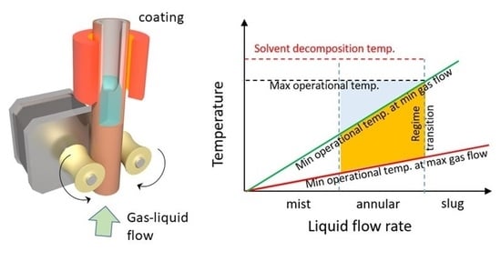
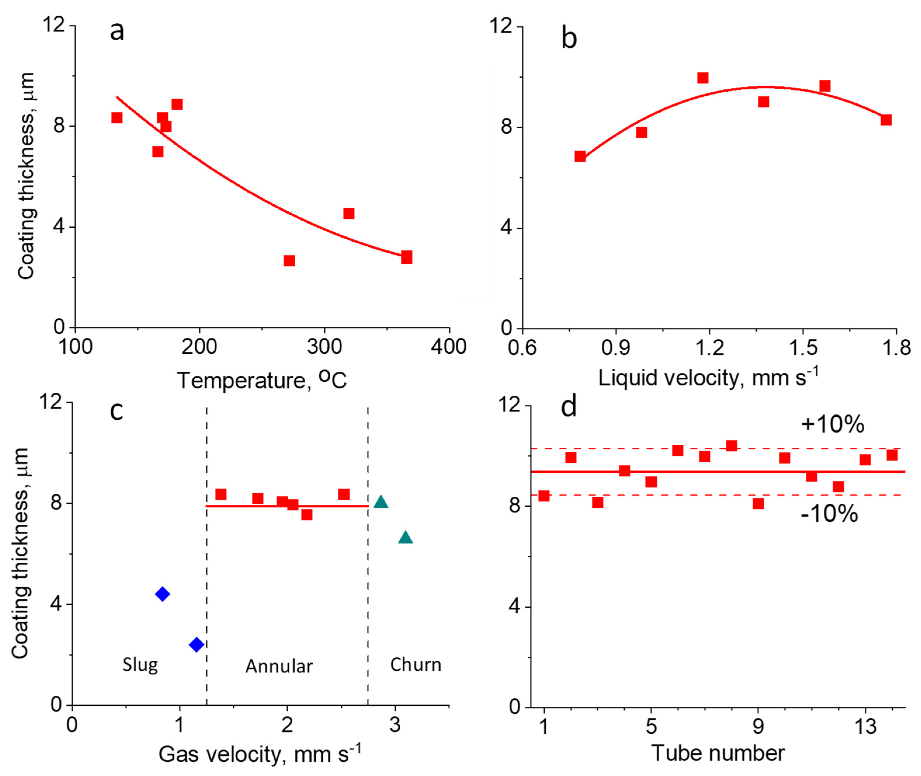
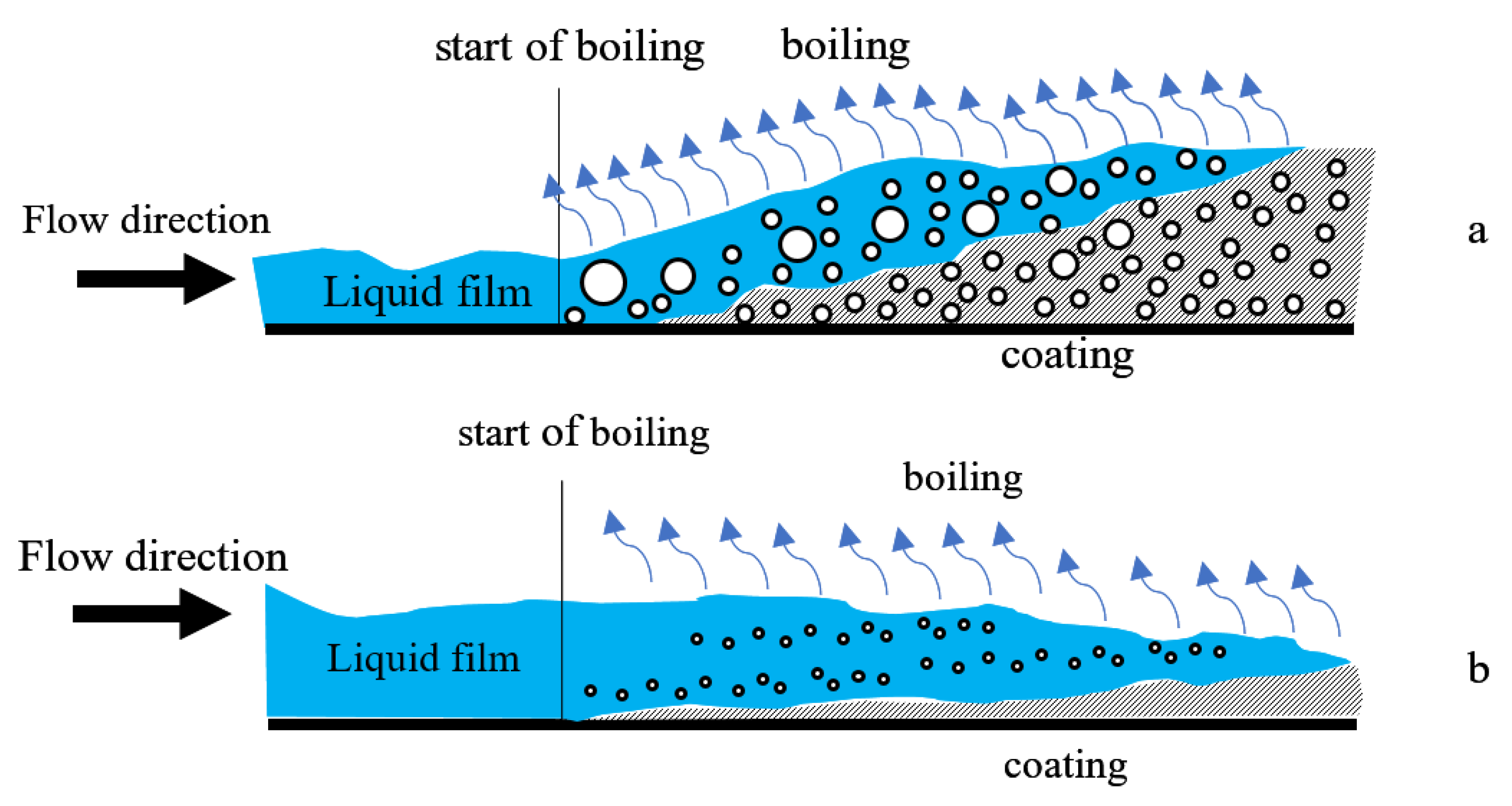
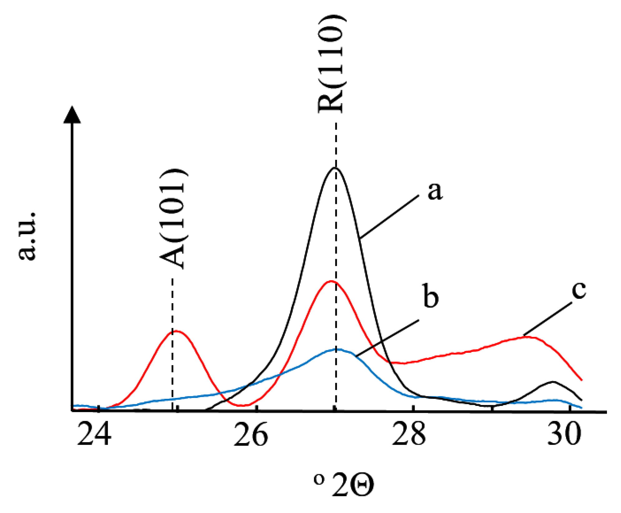
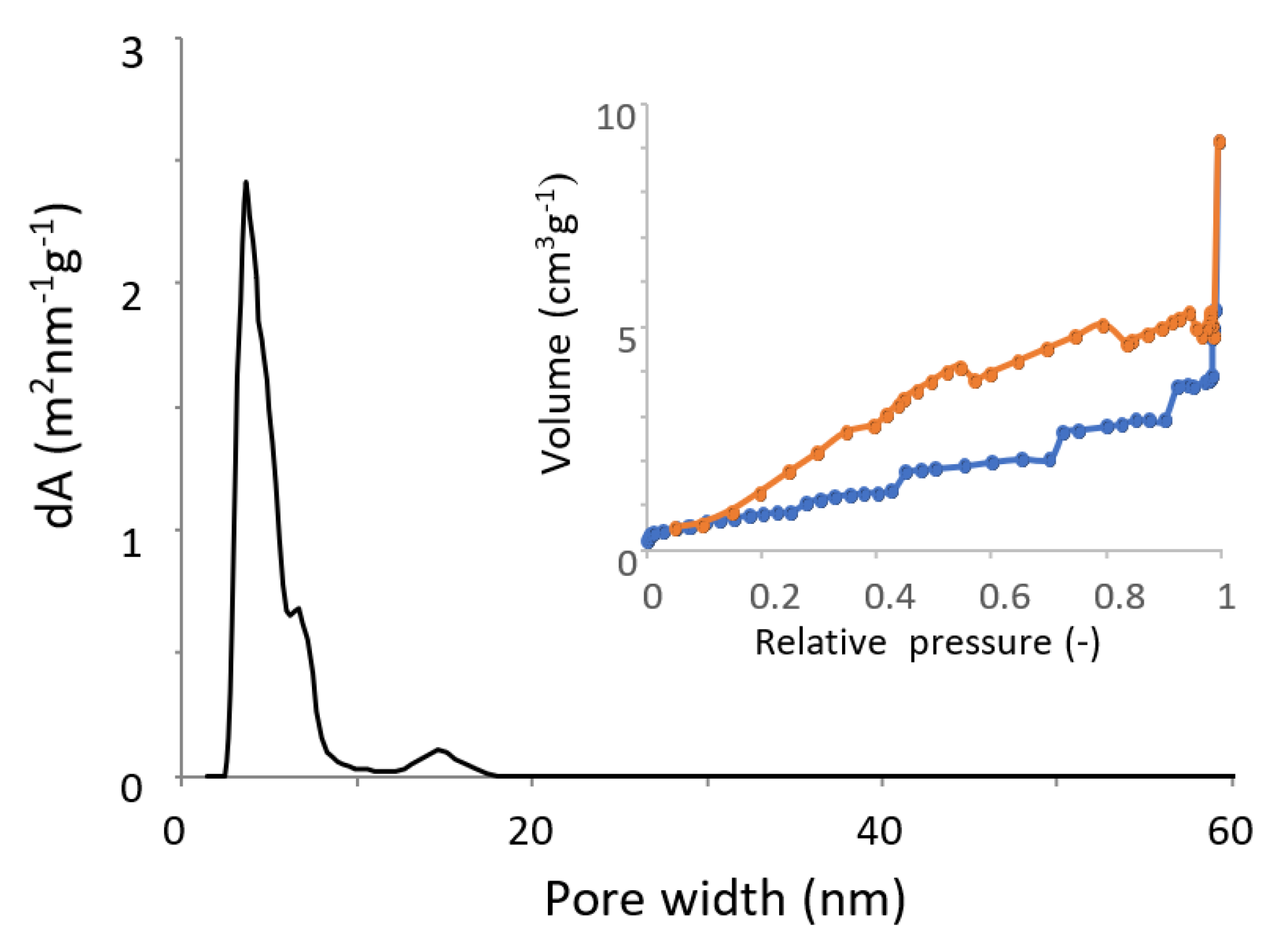
2. Results and Discussion

An annular gas-liquid flow regime was chosen for coating deposition. In this regime, the liquid flows as a thin film near the inner channel wall, while gas flows in the center of the tube.
Such flow conditions provide a good thermal contact between the liquid and the channel wall, so the boiling rate can be controlled by the thickness of the flowing liquid film and the temperature excess (the difference between the actual temperature and the boiling temperature), similar to a single-phase flow. The presence of the gas core prevents the formation of solid plugs which were previously observed when large liquid slugs were present in the channel.
The effect of gas and liquid flow rates and the oven temperature on the average thickness of the titania coatings was studied in three series of experiments. In series A, the effect of temperature was studied at a fixed gas and liquid velocity of 2.3 m s−1 and 1.2 mm s−1, respectively (Figure 1a). The preheater temperature was set to prevent boiling before the furnace. Increasing the temperature increases the boiling rate and leads to the formation of more dense titania coatings. Therefore, the mean coating thickness monotonously decreases with temperature. In this temperature range, vaporization of the liquid film is promoted by the lower latent heat of vaporization of solvent. On the contrary, very porous (foam-like) coatings were produced in the temperature range above 150 °C. These coatings were rather fragile and a considerable amount of material was detached from the surface in the subsequent calcination step. Thus, the resulting thickness of the coatings obtained at elevated evaporator temperatures is less than in the case of moderate temperatures. The solvent was partially decomposed, and the coatings were gray in color after deposition due to the presence of carbon deposits. Therefore, the maximum temperature was fixed to 150 °C in the subsequent optimization experiments.
In series B, the effect of liquid velocity on the coating thickness was studied at a constant temperature and a constant gas flow rate (Figure 1b). The range of flow rates between 0.6 and 1.8 mm s−1 was chosen based on the results of our previous study [34]. Previously, contrasting trends were obtained, with the coating thickness either decreasing or increasing by increase of liquid mass flow rate. The increase of boiling rate can be attributed to a coalescence of gas bubbles, which increases the thermal flux and therefore the boiling rate. The increasing bubble nucleation frequency induced by the higher flow rate promotes bubble detachment from the wall due to increased drag force. Figure 1b shows that an increase of liquid flow rate enhances the heat transfer performance and the boiling rate, as a consequence of the thinner liquid film and thus higher evaporation and coating deposition rates. The higher coating mass in this flow range can be explained by the increased precursor evaporation rate [53].
The liquid also contains a large number of vapor bubbles, and rather porous coatings were formed with a larger thickness, as shown schematically in Figure 2a. The respective optical images are shown in Figure 3a–d. The white color of the coatings is due to multiple light reflections in their porous structure. However, an opposite trend was found in the higher liquid flow range, above 1.5 mm s−1. In this range, the coating thickness decreases as a result of higher bubble nucleation frequency and the formation of a continuous gas layer near the hot channel wall [54]. The bubbles prevent an efficient heat transfer to the liquid film and therefore the coating mass decreases (Figure 1b). Moreover, some droplets can be carried away from the liquid film by the gas flow (Figure 3e) and they do not contribute to the formation of coating. Nucleate boiling does not occur at these conditions and the coatings formed are semi-transparent films without a developed pore structure (Figure 3e,f). A schematic mechanism for their formation in shown in Figure 2b. A similar mechanism was observed at higher process temperatures corresponding to high heat fluxes.
The gas velocity has a minor effect on the coating thickness under annular flow regime (Figure 1c). With increasing flow rate above 2.0 m s−1, a significant amount of liquid becomes transferred from the annular film to the gas core. At a gas velocity of 2.8 m s−1, a transition to mist flow regime occurs where all of the liquid is entrained in the gas flow. Due to the large drop in heat-transfer coefficient that accompanies tube wall dryout in the mist flow, the evaporation rate decreases, and this leads to a decrease in the coating thickness (Figure 1c). On the other side, a transition to slug flow occurs below a gas velocity of 1.3 m s−1. In the periodic passage of elongated bubbles and liquid slugs which is characteristic of the slug flow pattern, the maximum heat transfer rate is achieved when the elongated bubbles are formed at relatively low gas flow rates (below 1 m s−1).
The XRD diffractogram of the coatings obtained in the slug and annular flow regimes are shown in Figure 4. Due to a rather low coating thickness, the scanning range was limited to 24–31° 2-thetas to reduce the beam time, however no impurities of other phases were observed when a wider range of angles was analyzed. Due to a sharp curvature of the coated tubes, the measurements in a wider range are very time consuming as they result in a large scattering and a very low signal to noise ratio requiring very low XRD scanning rates. The presence of other reflections could be hindered by a preferred orientation of the crystals onto the tube wall. The main phase was rutile, as confirmed by its strongest peak at 27.0° 2-theta while small amounts of anatase were also present in the samples obtained in the annular flow regime. The positions of the strongest XRD peaks were consistent with the standard XRD data of the anatase and rutile TiO2 phase (JCPDS no. 21-1272 and JCPDS no. 21-1276, respectively).
The formation of anatase occurs in a lower temperature range as compared to that of rutile. This allows to conclude that the surface temperature was lower in the annular flow regime due to the much higher heat transfer rate, which is in line with the previous discussion. It should be mentioned that the temperature of anatase to rutile transition depends also on the particle size, shape of the nanostructure, and presence of dopants and structural defects [55,56]. However, these parameters were very similar in all samples. Therefore, the phase composition of the resulting coatings is mainly determined by the hydrodynamics of two-phase flow and the related heat transfer rates. The sample obtained in the annular regime demonstrated an apparent density of 3.37 kg m−3, which was increased to 3.85 kg m−3 after calcination. Moreover, the anatase phase completely disappeared after the additional calcination step (Figure 4). A non-porous rutile has a density of 4.24 g cm−3. Thus, a simple estimation shows that the porosity of coatings decreases from 20.5% to 9.2% after calcination. Based on the above data, it can be concluded that optimal conditions correspond to a temperature of 115–120 °C, a liquid velocity of 1.2 mm s−1, and a gas velocity of 1.4–2.6 m s−1.
Figure 5 shows SEM images of coating produced in the annular flow regime under optimized process conditions. It can be seen that the mean coating thickness is about 9 μm, and it reduced to 7 μm after an additional calcination step at 400 °C. These data are in good agreement with the data obtained from the gravimetric analysis. The respective N2 adsorption-desorption isotherms and the pore-size distribution are shown in Figure 6. The specific surface area of the coating was 9.2 m2g−1 with a mean pore size of 5.1 nm. The mean crystallite size obtained from the XRD analysis is 10 nm. This corresponds to a low end of the range of particle sizes observed in P25 titania catalysts. The P25 titania can be seen as benchmarking for the coatings produced in this study. It has a wide particle size distribution between 10 and 40 nm and a typical surface area of 50 m2g−1, while the coatings obtained in this study demonstrated a value five times smaller. It appears that a large part of the coatings has no porosity and therefore it is not accessible for N2 adsorption. As no structure directing agents were used in the synthesis sol (see experimental section), the formation of a partially non-porous coating cannot be excluded. A coating porosity in the 10–20% range also supports this conclusion.
The reproducibility of the coating method was studied by coating fourteen tubes under optimized process conditions. It can be seen in Figure 1d that the relative standard deviation was 12%, demonstrating the rather good reproducibility of the method.
The operational window of the method is shown in Figure 7. The minimum temperature of deposition is obtained from the energy balance in the system when the heat transfer rate is equal to the rate of solvent evaporation.
h A ( T b T s a t ) = m ˙ L Δ H ,
where h is the heat transfer coefficient, A is the inner surface area of the tube, Tb is the wall temperature, Tsat is the temperature of evaporation, m ˙ L is the liquid mass flow rate, and Δ H is the enthalpy of solvent evaporation. This energy balance can be assumed based on the fact that as the liquid is already preheated to the evaporation temperature in the preheater section, the heating of the gas phase above the boiling temperature can be neglected. The rearrangement of Equation (1) allows to estimate the minimum boiling temperature as a function of liquid flow rate:
T b = Δ H · m ˙ L h · A + T s a t
The heat transfer coefficient increases at high gas flow rate and therefore the slope of the minimum temperature line (shown in red in Figure 7) decreases. The two vertical lines show the transitions to the slug and churn flow regimes where the operation should be avoided. Finally, the upper temperature range, shown by a horizontal maximum operational temperature line in Figure 7, should always be below the solvent decomposition temperature. The exact difference depends on the solvent type and usually stays in the range of 10–30 K. In this study, the maximum operational temperature corresponding to the formation of continuous coatings is limited to 135 °C. It can further be decreased to 115 °C (minimum operational temperature) by increasing the gas flow rate from 1.4 to 2.6 m s−1.
The coatings obtained were tested in the decomposition of two organic compounds at 20 °C. The kinetic data were corrected by subtracting the rate of non-catalytic reaction measured in a blank experiment with a non-coated tube. The ln(C0/C) values versus time provided a straight line (Figure 8). Therefore, the photocatalytic reaction rate is described by a first order kinetics with a rate constant of 0.0120 min−1 for MB and 0.0253 min−1 for RhB. The value reported for MB is in a very good agreement with that (0.014 min−1) reported over a P25 titania catalyst [57]. The rate constant for the decomposition of RhB exceeds this value (0.0194 min−1) reported over a TiO2/SiC catalyst [16].

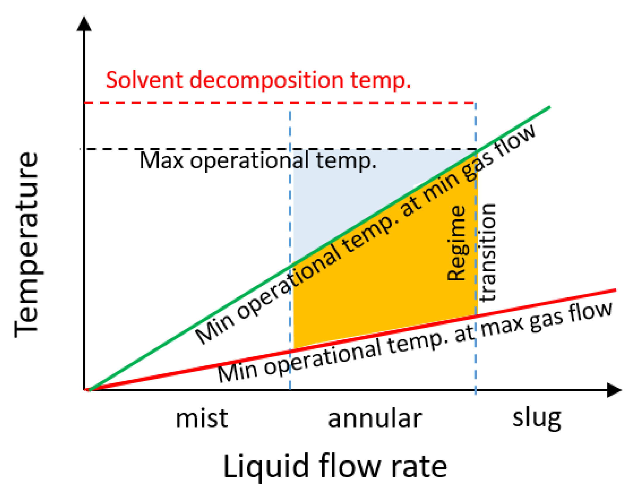
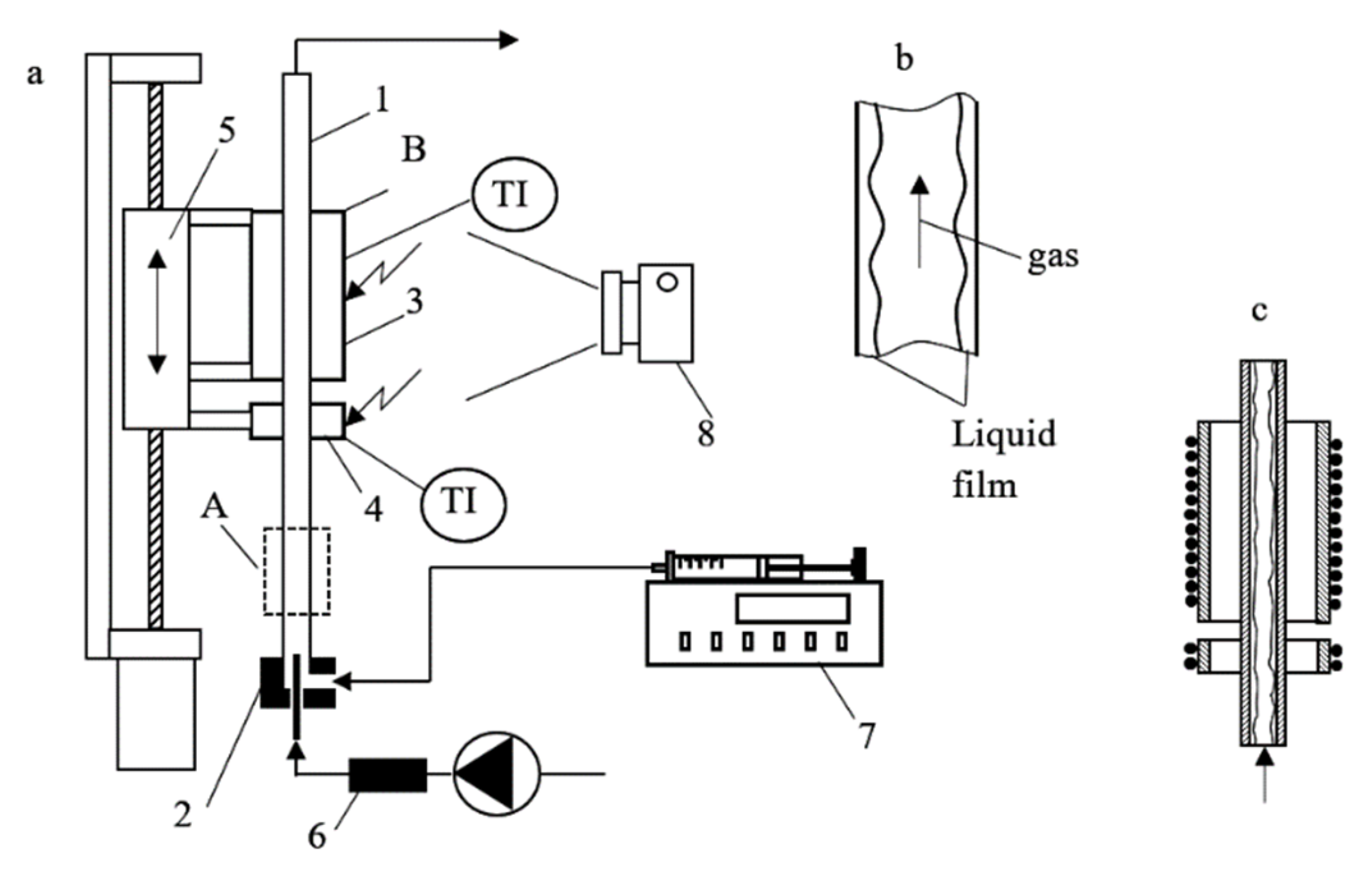
3. Materials and Methods

The initial sol was prepared from titanium isopropoxide (97.0 wt.%, Sigma-Aldrich, St. Louis, MO, USA), isopropanol (99.5 wt.%, Sigma-Aldrich, St. Louis, MO, USA) and HNO3 (65 wt%, Sigma-Aldrich). First, a solution of nitric acid (0.1 mL) was added to isopropanol (8.45 g) to obtain a solution A. Then, titanium isopropoxide was added dropwise to solution A to obtain the final solution. The mixture was preheated to 60 °C and stirred for 2 h. Figure 9 shows the experimental set-up employed for coating deposition. The nitrogen flow and the flow of synthesis mixture were mixed in a coaxial mixer and fed to a tubular furnace via a preheater section. The quartz tube (i.d. 3.0 mm, o.d. 4.0 mm) was positioned vertically in a furnace with a 50 mm length. The liquid solution was fed with a syringe pump and the gas flow was fed with a mass flow controller. In this study, the liquid flow rate was varied from 0.33 to 0.75 mL min−1 and the gas flow rate was varied from 0.43 to 1.27 L min−1. The temperature in the preheater section was set just below the boiling temperature of the synthesis mixture, while the temperature in the furnace was varied in the 115–350 °C range. The images of the gas-liquid flow were recorded using a high-speed videocamera. In the beginning of each experiment, a gas-liquid flow was fed in the tube. Once the temperature of the tubular furnace reached the setpoint, the quartz tube was fed to the furnace using a stepper motor. The tube displacement speed was fixed at 1.6 mm s−1. At the end of each deposition run, the coated tube was detached from the connecting lines and annealed in an oven at 400 °C for 3 h with a heating rate of 1 K min−1.
For analysis, the tubes were cut into short sections with a length of 15 mm. The XRD patterns were recorded with a Shimadzu XRD-7000 diffractometer in the 23–32° 2θ range using a CuKα irradiation. The scanning rate was 2.0° 2-theta min−1. The specific surface area and the pore volume were obtained from N2 adsorption-desorption isotherms obtained on a Quantachrome Autosorb-6iSA apparatus. For these measurements, the coatings obtained were mechanically removed from the inner tube wall. Before the measurements, the samples were degassed at 250 °C for 1 h. The specific surface area was calculated using a multi-point BET method from the adsorption isotherm. The mean coating thickness ( δ ) was determined by Equation (3).
δ = Δ m ρ c · π · d · L t
where Δm is the weight change after coating deposition, ρc is the apparent coating density determined from the sample porosity, d is the tube inner diameter, and Lt is the coated length. In this method, the coating (geometrical) volume was approximated by the product of π · d · δ · L t . The apparent coating density was calculated by Equation (4):
ρ c = m V T i O 2 + V p
where VTiO2 is the specific volume of titania, Vp is the specific pore volume.
The decomposition of methylene blue (C16H18ClN3S, MB) and rhodamine B (C28H31ClN2O3, RhB) was studied in the coated tubes at 20 °C under stop flow conditions under UV light (power: 26 W in the range of 320–370 nm) illuminated from a distance of 2 cm. The solution volume in the tube was 0.87 mL. The size of the light source was considerably larger than the illuminated reactor area, providing a uniform intensity over the entire length.
RhB and MB dyes (purity ≥ 99.0 wt.%) were obtained from Fluka. The initial concentrations of MB and RhB were 10.0 and 5.0 mg L−1, respectively. After the initial adsorption in the dark, the concentration decreased by 4%. The concentration was measured with a UV-VIS spectrometer (UV-1800, Shimadzu, Kyoto, Japan) using calibration curves. A quartz cuvette with an optical path of 10 mm was used. The samples were diluted 10 times in distilled water for analysis. Blank experiments were also carried out with non-coated quartz tubes to obtain the rate of non-catalytic decomposition at the same experimental conditions.

4. Conclusions

An operational window for the evaporation-deposition method for the controlled deposition of micrometer-thick titania coatings on the inner surface of long quartz tubes has been studied. The liquid flow rate and the oven temperature were the most important parameters that control coating morphology. In particular, the effect of liquid velocity in the range of 0.8–1.8 mm s−1 and the boiling temperature in the range of 115–350 °C was systematically investigated. The operation in the annular flow regime allows to reduce the coating deposition temperature from 135 to 115 °C by increasing the gas flow rate from 1.4 to 2.6 mm s−1. This allows uniform solvent removal leading to the formation of continuous coatings with an average thickness in the range between 3 and 10 mm. The porosity of the coatings decreases with increasing liquid flow rate. The preheating of the precursor mixture to the temperature just below its boiling point was an important factor to increase the reproducibility of the method. A mean standard deviation in the coating thickness of 12% was obtained under optimised conditions. The coatings obtained were active in the reactions of photocatalytic decomposition of methylene blue and rhodamine B with no observed catalyst deactivation. The photocatalytic reaction rates were comparable to those previously reported over P25 titania catalysts.

Author Contributions

Conceptualization, E.V.R. and S.D.S.; methodology, R.S.A.; formal analysis, S.D.S.; investigation, S.D.S., D.A.S., K.V.S. and A.V.U.; writing—original draft preparation, S.D.S.; review and editing, E.V.R.; supervision, R.S.A. and E.V.R.; funding acquisition, E.V.R. All authors have read and agreed to the published version of the manuscript.

Funding

This research was funded by the Russian Science Foundation, grant number 20-69-46041.

Data Availability Statement

Not applicable.

Acknowledgments

The authors would like to thank Yuyan Gong from the University of Warwick for SEM analysis.

Conflicts of Interest

The authors declare no conflict of interest.

References

  1. Sacco, O.; Vaiano, V.; Rizzo, L.; Sannino, D. Photocatalytic activity of a visible light active structured photocatalyst developed for municipal wastewater treatment. J. Clean. Prod. 2018, 175, 38–49. [Google Scholar] [CrossRef]
  2. Yang, H.; Yang, J. Photocatalytic degradation of rhodamine B catalyzed by TiO2 films on a capillary column. RSC Adv. 2018, 8, 11921–11929. [Google Scholar] [CrossRef] [Green Version]
  3. Zhang, Q.; Fu, Y.; Wu, Y.; Zhang, Y.N.; Zuo, T. Low-Cost Y-Doped TiO2 Nanosheets film with highly reactive {001} facets from CRT waste and enhanced photocatalytic removal of Cr(VI) and methyl orange. ACS Sustain. Chem. Eng. 2016, 4, 1794–1803. [Google Scholar] [CrossRef]
  4. Zhao, J.; Yang, Y.; Li, Y.; Zhao, L.; Wang, H.; Song, G.; Tang, G. Microencapsulated phase change materials with TiO2-doped PMMA shell for thermal energy storage and UV-shielding. Sol. Energy Mater. Sol. Cells 2017, 168, 62–68. [Google Scholar] [CrossRef]
  5. Endres, P.J.; Paunesku, T.; Vogt, S.; Meade, T.J.; Woloschak, G.E. DNA-TiO2 nanoconjugates labeled with magnetic resonance contrast agents. J. Am. Chem. Soc. 2007, 129, 15760–15761. [Google Scholar] [CrossRef] [PubMed]
  6. Fitra, M.; Daut, I.; Irwanto, M.; Gomesh, N.; Irwan, Y.M. Effect of TiO2 thickness dye solar cell on charge generation. Energy Procedia 2013, 36, 278–286. [Google Scholar] [CrossRef] [Green Version]
  7. Yang, H.; Zhu, S.; Pan, N. Studying the mechanisms of titanium dioxide as ultraviolet-blocking additive for films and fabrics by an improved scheme. J. Appl. Polym. Sci. 2004, 92, 3201–3210. [Google Scholar] [CrossRef]
  8. Cardoso, B.N.; Kohlrausch, E.C.; Laranjo, M.T.; Benvenutti, E.V.; Balzaretti, N.M.; Arenas, L.T.; Santos, M.J.L.; Costa, T.M.H. Tuning anatase-rutile phase transition temperature: TiO2/SiO2 nanoparticles applied in dye-sensitized solar cells. Int. J. Photoenergy 2019, 2019, 7183978. [Google Scholar] [CrossRef]
  9. Luttrell, T.; Halpegamage, S.; Tao, J.; Kramer, A.; Sutter, E.; Batzill, M. Why is anatase a better photocatalyst than rutile?—Model studies on epitaxial TiO2 films. Sci. Rep. 2015, 4, 4043. [Google Scholar] [CrossRef] [Green Version]
  10. Wu, J.M. Photodegradation of rhodamine B in water assisted by titania nanorod thin films subjected to various thermal treatments. Environ. Sci. Technol. 2007, 41, 1723–1728. [Google Scholar] [CrossRef]
  11. Crişan, M.; Mardare, D.; Ianculescu, A.; Drăgan, N.; Niţoi, I.; Crişan, D.; Voicescu, M.; Todan, L.; Oancea, P.; Adomniţei, C.; et al. Iron doped TiO2 films and their photoactivity in nitrobenzene removal from water. Appl. Surf. Sci. 2018, 455, 201–215. [Google Scholar] [CrossRef]
  12. Bisen, N.; Shrivastava, P.; Hariprasad, N.; Anju, S.G.; Yesodharan, E.P.; Suguna, Y.; Gaya, U.I.; Abdullah, A.H.; Tseng, T.K.; Lin, Y.S.; et al. Sunlight induced removal of Rhodamine B from water through Semiconductor Photocatalysis: Effects of adsorption, reaction conditions and additives. Int. J. Mol. Sci. 2013, 11, 2336–2361. [Google Scholar]
  13. Van Viet, P.; Sang, T.T.; Hien, N.Q.; Thi, C.M.; Hieu, L. Synthesis of a silver/TiO2 nanotube nanocomposite by gamma irradiation for enhanced photocatalytic activity under sunlight. Nucl. Instrum. Methods Phys. Res. Sect. B Beam Interact. Mater. Atoms 2018, 429, 14–18. [Google Scholar] [CrossRef]
  14. Sanzone, G.; Zimbone, M.; Cacciato, G.; Ruffino, F.; Carles, R.; Privitera, V.; Grimaldi, M.G. Ag/TiO2 nanocomposite for visible light-driven photocatalysis. Superlattices Microstruct. 2018, 123, 394–402. [Google Scholar] [CrossRef]
  15. Hafizah, N.; Sopyan, I. Cement bonded sol-gel TiO2 powder photocatalysis for phenol removal. Appl. Mech. Mater. 2015, 776, 271–276. [Google Scholar] [CrossRef]
  16. Allé, P.H.; Fanou, G.D.; Robert, D.; Adouby, K.; Drogui, P. Photocatalytic degradation of Rhodamine B dye with TiO2 immobilized on SiC foam using full factorial design. Appl. Water Sci. 2020, 10, 207. [Google Scholar] [CrossRef]
  17. Meille, V. Review on methods to deposit catalysts on structured surfaces. Appl. Catal. A 2006, 315, 1–17. [Google Scholar] [CrossRef]
  18. Agrafiotis, C.; Tsetsekou, A.; Stournaras, C.J.; Julbe, A.; Dalmazio, L.; Guizard, C. Evaluation of sol-gel methods for the synthesis of doped-ceria environmental catalysis systems. Part I: Preparation of coatings. J. Eur. Ceram. Soc. 2002, 22, 15–25. [Google Scholar] [CrossRef]
  19. McCarty, J.G. Kinetics of PdO combustion catalysis. Catal. Today 1995, 26, 283–293. [Google Scholar] [CrossRef]
  20. Rice, C.V.; Raftery, D. Photocatalytic oxidation of trichloroethylene using TiO2 coated optical microfibers. Chem. Commun. 1999, 10, 895–896. [Google Scholar] [CrossRef]
  21. Belochapkine, S.; Shaw, J.; Wenn, D.; Ross, J.R.H. The synthesis by deposition-precipitation of porous γ-alumina catalyst supports on glass substrates compatible with microreactor geometries. Catal. Today 2005, 110, 53–57. [Google Scholar] [CrossRef]
  22. Cini, P.; Blaha, S.R.; Harold, M.P.; Venkataraman, K. Preparation and characterization of modified tubular ceramic membranes for use as catalyst supports. J. Memb. Sci. 1991, 55, 199–225. [Google Scholar] [CrossRef]
  23. Xiaoding, X.; Vonk, H.; Cybulski, A.; Moulijn, J.A. Alumina washcoating and metal deposition of ceramic monoliths. Stud. Surf. Sci. Catal. 1995, 91, 1069–1078. [Google Scholar] [CrossRef]
  24. Rebrov, E.V.; Klinger, E.A.; Berenguer-Murcia, A.; Sulman, E.M.; Schouten, J.C. Selective hydrogenation of 2-methyl-3-butyne-2-ol in a wall-coated capillary microreactor with a Pd25Zn75/TiO2 catalyst. Org. Process Res. Dev. 2009, 13, 991–998. [Google Scholar] [CrossRef]
  25. Rebrov, E.V. Sol-gel synthesis of zeolite coatings and their application in catalytic microstructured reactors. Catal. Ind. 2009, 1, 322–347. [Google Scholar] [CrossRef]
  26. Jiang, P.; Lu, G.; Guo, Y.; Guo, Y.; Zhang, S.; Wang, X. Preparation and properties of a γ-Al2O3 washcoat deposited on a ceramic honeycomb. Surf. Coat. Technol. 2005, 190, 314–320. [Google Scholar] [CrossRef]
  27. Stefanov, P.; Stoychev, D.; Valov, I.; Kakanakova-Georgieva, A.; Marinova, T. Electrochemical deposition of thin zirconia films on stainless steel 316 L. Mater. Chem. Phys. 2000, 65, 222–225. [Google Scholar] [CrossRef]
  28. Matatov-Meytal, Y.; Barelko, V.; Yuranov, I.; Sheintuch, M. Cloth catalysts in water denitrification. I. Pd on glass fibers. Appl. Catal. B 2000, 27, 127–135. [Google Scholar] [CrossRef]
  29. Ismagilov, Z.R.; Matus, E.V.; Yakutova, A.M.; Protasova, L.N.; Ismagilov, I.Z.; Kerzhentsev, M.A.; Rebrov, E.V.; Schouten, J.C. Design of Pt-Sn catalysts on mesoporous titania films for microreactor application. Catal. Today 2009, 147, S81–S86. [Google Scholar] [CrossRef]
  30. Giornelli, T.; Löfberg, A.; Bordes-Richard, E. Grafting of VOx/TiO2 catalyst on anodized aluminum plates for structured catalytic reactors. Thin Solid Films 2005, 479, 64–72. [Google Scholar] [CrossRef]
  31. Protasova, L.N.; Rebrov, E.V.; Glazneva, T.S.; Berenguer-Murcia, A.; Ismagilov, Z.R.; Schouten, J.C. Control of the thickness of mesoporous titania films for application in multiphase catalytic microreactors. J. Catal. 2010, 271, 161–169. [Google Scholar] [CrossRef]
  32. Pan, J.H.; Zhao, X.S.; Lee, W.I. Block copolymer-templated synthesis of highly organized mesoporous TiO2-based films and their photoelectrochemical applications. Chem. Eng. J. 2011, 170, 363–380. [Google Scholar] [CrossRef]
  33. Bravo, J.; Karim, A.; Conant, T.; Lopez, G.P.; Datye, A. Wall coating of a CuO/ZnO/Al2O3 methanol steam reforming catalyst for micro-channel reformers. Chem. Eng. J. 2004, 101, 113–121. [Google Scholar] [CrossRef]
  34. Cherkasov, N.; Ibhadon, A.O.; Rebrov, E.V. Novel synthesis of thick wall coatings of titania supported Bi poisoned Pd catalysts and application in selective hydrogenation of acetylene alcohols in capillary microreactors. Lab Chip 2015, 15, 1952–1960. [Google Scholar] [CrossRef] [PubMed]
  35. Rebrov, E.V.; Cherkasov, N. Disruptive technology for fine chemicals synthesis with catalyst-coated tube reactors. Chim. Oggi/Chem. Today 2018, 36, 17–20. [Google Scholar] [CrossRef]
  36. Cherkasov, N.; Ibhadon, A.O.; Rebrov, E.V. Solvent-free semihydrogenation of acetylene alcohols in a capillary reactor coated with a Pd-Bi/TiO2 catalyst. Appl. Catal. A 2016, 515, 108–115. [Google Scholar] [CrossRef] [Green Version]
  37. Exposito, A.J.; Bai, Y.; Tchabanenko, K.; Rebrov, E.V.; Cherkasov, N. Process intensification of continuous-flow imine hydrogenation in catalyst-coated tube reactors. Ind. Eng. Chem. Res. 2019, 58, 4433–4442. [Google Scholar] [CrossRef]
  38. Rebrov, E.V. Two-phase flow regimes in microchannels. Theor. Found. Chem. Eng. 2010, 44, 355–367. [Google Scholar] [CrossRef]
  39. Warnier, M.J.F. Taylor Flow Hydrodynamics in Gas-Liquid-Solid Micro Reactors; Technische Universiteit Eindhoven: Eindhoven, The Netherlands, 2009. [Google Scholar]
  40. Qu, W.; Mudawar, I. Flow boiling heat transfer in two-phase micro-channel heat sinks—II. Annular two-phase flow model. Int. J. Heat Mass Transf. 2003, 46, 2773–2784. [Google Scholar] [CrossRef]
  41. Yang, F.; Dai, X.; Peles, Y.; Cheng, P.; Khan, J.; Li, C. Flow boiling phenomena in a single annular flow regime in microchannels (I): Characterization of flow boiling heat transfer. Int. J. Heat Mass Transf. 2014, 68, 703–715. [Google Scholar] [CrossRef]
  42. Abiev, R.S. Hydrodynamics and heat transfer of circulating Two-phase Taylor flow in microchannel heat pipe: Experimental study and Mathematical Model. Ind. Eng. Chem. Res. 2020, 59, 3687–3701. [Google Scholar] [CrossRef]
  43. Peterson, G.P.; Ma, H.B. Theoretical analysis of the maximum heat transport in triangular grooves: A study of idealized micro heat pipes. J. Heat Transf. 1996, 118, 731–739. [Google Scholar] [CrossRef]
  44. Helbig, K.; Alexeev, A.; Gambaryan-Roisman, T.; Stephan, P. Evaporation of falling and shear-driven thin films on smooth and grooved surfaces. Flow, Turbul. Combust. 2005, 75, 85–104. [Google Scholar] [CrossRef]
  45. Sibiryakov, N.; Kabov, O.; Belosludstev, V. Numerical simulation of flow in triangular minichannel. EPJ Web Conf. 2019, 196, 00051. [Google Scholar] [CrossRef] [Green Version]
  46. Sibiryakov, N.; Kabov, O. Numerical simulation of flow with evaporation in triangular grooves. J. Phys. Conf. Ser. 2019, 1369, 012060. [Google Scholar] [CrossRef]
  47. Warrier, G.R.; Dhir, V.K.; Momoda, L.A. Heat transfer and pressure drop in narrow rectangular channels. Exp. Therm. Fluid Sci. 2002, 26, 53–64. [Google Scholar] [CrossRef]
  48. Lazarek, G.M.; Black, S.H. Evaporative heat transfer, pressure drop and critical heat flux in a small vertical tube with R-113. Int. J. Heat Mass Transf. 1982, 25, 945–960. [Google Scholar] [CrossRef]
  49. Kandlikar, S.G. A general correlation for saturated two-phase flow boiling heat transfer inside horizontal and vertical tubes. J. Heat Transfer 1990, 112, 219–228. [Google Scholar] [CrossRef] [Green Version]
  50. Liu, Z.; Winterton, R.H.S. A general correlation for saturated and subcooled flow boiling in tubes and annuli, based on a nucleate pool boiling equation. Int. J. Heat Mass Transf. 1991, 34, 2759–2766. [Google Scholar] [CrossRef]
  51. Nayar, K.G.; Panchanathan, D.; McKinley, G.H.; Lienhard, J.H. Surface Tension of Seawater. J. Phys. Chem. Ref. Data 2014, 43, 043103. [Google Scholar] [CrossRef] [Green Version]
  52. Wang, Z.; Karapetsas, G.; Valluri, P.; Sefiane, K.; Williams, A.; Takata, Y. Dynamics of hygroscopic aqueous solution droplets undergoing evaporation or vapour absorption. J. Fluid Mech. 2021, 912, 1–30. [Google Scholar] [CrossRef]
  53. Fukano, T.; Furukawa, T. Prediction of the effects of liquid viscosity on interfacial shear stress and frictional pressure drop in vertical upward gas-liquid annular flow. Int. J. Multiph. Flow 1998, 24, 587–603. [Google Scholar] [CrossRef]
  54. Magnini, M.; Thome, J.R. A CFD study of the parameters influencing heat transfer in microchannel slug flow boiling. Int. J. Therm. Sci. 2016, 110, 119–136. [Google Scholar] [CrossRef] [Green Version]
  55. Zhang, H.; Chen, B.; Banfield, J.F. The size dependence of the surface free energy of titania nanocrystals. Phys. Chem. Chem. Phys. 2009, 11, 2553–2558. [Google Scholar] [CrossRef] [PubMed]
  56. Zhang, H.; Banfield, J.F. Understanding polymorphic phase transformation behavior during growth of nanocrystalline aggregates: Insights from TiO2. J. Phys. Chem. B 2000, 104, 3481–3487. [Google Scholar] [CrossRef]
  57. Le, H.A.; Linh, L.T.; Chin, S.; Jurng, J. Photocatalytic degradation of methylene blue by a combination of TiO2-anatase and coconut shell activated carbon. Powder Technol. 2012, 225, 167–175. [Google Scholar] [CrossRef]
Figure 1. Effect of (a) oven temperature, (b) liquid velocity; (c) gas velocity onto the mean coating thickness in as-synthesized samples, the two vertical dashed lines show flow regime transitions; (d) reproducibility experiments performed at optimised conditions (liquid flow rate: 1.2 mm s−1, gas flow rate: 2.0 m s−1, temperature: 115 °C).
Catalysts 11 01538 g001
Figure 2. Schematic mechanism of coating formation. (a) formation of porous coatings at liquid flow rate of 0.8–1.5 mm s−1, (b) formation of dense semi-transparent coatings at liquid flow rate of 1.5–1.8 mm s−1.
Catalysts 11 01538 g002
Figure 3. Images of coated tubes obtained at different liquid flow velocities: (a) 0.8, (b) 1.0, (c) 1.2, (d) 1.4, (e) 1.6, (f) 1.8 mm s−1. Temperature: 115 °C, gas flow rate: 2.0 m s−1.
Catalysts 11 01538 g003
Figure 4. XRD diffractogram of as-synthesized coatings obtained at different gas flow rates. Abbreviations: A—anatase, R—rutile. Gas flow rate: (a) 0.6 m s−1, (b) 1.0 m s−1, (c) 1.4 m s−1. Liquid flow rate: 1.2 mm s−1. Temperature: 115 °C.
Catalysts 11 01538 g004
Figure 5. SEM images of optimised coatings obtained at a liquid flow rate of 1.2 mm s−1 and a gas flow rate of 2.2 m s−1 in the annular flow regime. (a,b) as-synthesized, (c,d) after calcination at 400 °C.
Catalysts 11 01538 g005
Figure 6. Pore size distribution and nitrogen adsorption/desorption isotherms over the coating obtained at a liquid flow rate of 1.2 mm s−1 and a gas flow rate of 2.2 m s−1.
Catalysts 11 01538 g006
Figure 7. Operational window for coating deposition. The blue color shows the operational range at a minimum gas flow rate of 0.4 L min−1, the orange color shows the extension of operational range towards lower temperatures at a maximum gas flow rate of 1.0 L min−1.
Catalysts 11 01538 g007
Figure 8. Concentration of methylene blue (MB) and rhodamine B (RhB) as a function of time in stop flow conditions over a TiO2 coated tube. The coating was produced under the same conditions as those reported in Figure 5. The data are corrected based on the rate over non-coated tubes measured in blank experiments. The insert shows the fitting curves based on a first order kinetics.
Catalysts 11 01538 g008
Figure 9. Schematic view of the experimental set-up for coating deposition (a) general view: (1) quartz tube, (2) T-mixer, (3) tubular furnace, (4) electrical preheater section, (5) stepper motor, (6) mass flow controller, (7) syringe pump, (8) high speed camera, TI is the temperature indicator, (b) schematic view of annular flow regime, (c) enlarged view of the furnace and the preheater section.
Catalysts 11 01538 g009
Publisher’s Note: MDPI stays neutral with regard to jurisdictional claims in published maps and institutional affiliations.

