Article

Validation of a Fixed Bed Reactor Model for Dimethyl Ether Synthesis Using Pilot-Scale Plant Data

1
School of Chemical Engineering, Chonnam National University, 77 Yongbong-ro, Buk-gu, Gwangju 61186, Korea
2
Department of Environment and Energy Engineering, Chonnam National University, 77 Yongbong-ro, Buk-gu, Gwangju 61186, Korea
*
Authors to whom correspondence should be addressed.
Catalysts 2021, 11(12), 1522; https://doi.org/10.3390/catal11121522
Submission received: 4 November 2021 / Revised: 10 December 2021 / Accepted: 12 December 2021 / Published: 15 December 2021
(This article belongs to the Special Issue Modern Catalytic Reactor: From Active Center to Application Tests)

Abstract

:
The one-dimensional (1D) mathematical model of fixed bed reactor was developed for dimethyl ether (DME) synthesis at pilot-scale (capacity: 25–28 Nm3/h of syngas). The reaction rate, heat, and mass transfer equations were correlated with the effectiveness factor. The simulation results, including the temperature profile, CO conversion, DME selectivity, and DME yield of the outlet, were validated with experimental data. The average error ratios were below 9.3%, 8.1%, 7.8%, and 3.5% for the temperature of the reactor, CO conversion, DME selectivity, and DME yield, respectively. The sensitivity analysis of flow rate, feed pressure, H2:CO ratio, and CO2 mole fraction was investigated to demonstrate the applicability of this model.

1. Introduction

Due to the rise of the negative effects of fossil fuels on greenhouse gas emissions, the development of alternative fuels is an urgent task for researchers globally [1]. Recently, dimethyl ether (DME) has received wide attention as a potential fuel, especially for transportation [2,3,4,5,6]. A significant advantage is that the emission of NOx, SOx, and CO2 is near-zero upon combustion of DME. Brunetti et al. accounted that combustion of liquefied petroleum gas (LPG)/DME could reduce 30–80% and 5–15% of CO2 emission and NOx emission, respectively [7]. In addition, DME is associated with reduced engine noise, and a good cetane number (55–60), and could be stored and transported safely. The global DME market size was estimated at approximately 4 billion tonnes in 2014, registering a Compounded Annual Growth rate (CAGR) of 15.67% between 2015 and 2020 [8]. This confirms that DME production technology is an inevitable research topic in the field of energy.
Conventionally, the synthesis of DME includes two stages: the synthesis of methanol from syngas and the dehydration of methanol to DME [9]. The process which conducts the stages via two different reactors is called indirect or two-step production [10]. On the other hand, DME production through a single reactor is known as the direct method or one-step production [11]. Catalysts play a vital role in both technologies. The methanol formation from the syngas step is promoted by the metal-oxide catalysts such as CuO, ZnO, and Cr2O3 [12]. The methanol dehydration catalysts are mainly γ-Al2O3 and its modification [13]. The γ-Al2O3 has a high surface area, high selectivity and activity toward DME, and excellent stability for the dehydration of methanol [14]; however, its productivity is lower with the presence of water [15]. In order to overcome the weakness of γ-Al2O3, Catizzone et al. investigated the research on different zeolite catalysts such as BEA, EUO, FER, MFI, MOR, MTW, and TON [16,17], while Hosseininejad proposed Amberlysts 35 resin as a good activity for the reaction [18]. Even though the indirect route is implemented commercially, it has several drawbacks, including a high capital investment, high operating cost, and low DME conversion efficiency due to the limitation of the thermodynamic equilibrium of CO conversion to methanol [19]. The application of a single reactor exploiting the synergy effect of the hybrid catalyst could overcome these disadvantages [20]. The hybrid catalyst combines the metallic function of metal oxide and the solid-acid function of γ-Al2O3. Thus, as with the indirect process catalyst, the zeolite is investigated to increase the process efficiency, typically the CuZnZr-zeolite catalyst of Frusteri et al. [21,22] or CuO–ZnO–Al2O3/ZSM-5 of Cai et al. [23]. However, operating and designing reactors, such as water formation and CO2-CO conversion involving the combination function of hybrid catalyst, remain challenging [24].
Some of the researchers studying reactor configurations have attempted to improve direct DME synthesis efficiency. Air Product and Chemicals, Inc. proposed the use of slurry reactors, which are able to provide efficient heat management [25]. However, the high mass transfer resistance in this type of reactor affected DME yield significantly [26,27]. Moreover, the complication of the reactor is another disadvantage [28]. Lu et al. investigated a fluidized bed reactor and achieved almost 100% DME selectivity [29]. In contrast, the catalyst was quickly deactivated and lost because of the collision with the reactor wall. The fixed bed reactor is another popular type of reactor investigated in recent years due to the ease of operating, maintenance, and modification [30]. Nevertheless, because of the limitation in the thermodynamic and gas-solid interface, the catalyst is sintered and overheated [31]. Many simulation works are studied to enhance the fixed bed reactor performance. Ghavipour et al. carried out the modeling of the fixed bed reactor for methanol dehydration only [32]. Farsi proposed the 1D configuration of membrane fixed bed reactor and compared it with data obtained for methanol dehydration from Zagros Petrochemical Complex in Iran [33]. Song et al. simulated the reactor model with all direct method reactions and validated it with pilot plant data [34]. Their result showed good agreement between the reactor model and one experimental data set. In addition, there was no sensitive analysis based on major operating variables. This model should be validated with a variety of operating conditions to demonstrate its commercial feasibility.
This study proposed a shell and tube fixed-bed reactor model followed by validation with pilot test results. The experiment data were collected through the steady-state operating period in the pilot. The performance of the pilot plant was determined based on the yield of DME, CO conversion rate, and DME selectivity. The pilot test was conducted by varying the temperature, pressure, syngas flow rate, and H2:C ratio. In addition, sensitive analysis of significant operating variables was carried out with the design simulation to analyze the effect of unstable conditions on the process performance. This study presented valuable data which could be used for future research focusing on DME synthesis reactor at commercial stages.

2. Methodology

2.1. Reactor Model Development

2.1.1. Reactor Model Assumptions

The following assumptions were made:
(1)
The model is a 1D (one-dimensional) heterogeneous model.
(2)
On the reactor tube, the radial temperature is negligible, as is the axial dispersion, due to the large ratio of catalyst bed length, the tube diameter, and catalyst particle diameter (the values are provided in Table 1) [35,36].
(3)
The radial temperature is inappreciable in the catalyst pellets since its conductivity is sufficiently high to reduce the core and surface temperature difference [37].
(4)
The deactivation of the catalyst is ignored due to a significant life time of this catalyst.

2.1.2. Reaction Kinetic Model

The production of DME from syngas (CO, CO2, H2 mixture) was expressed by the three following reactions [34]:
CO 2 + 3 H 2 CH 3 OH +   H 2 O
CO +   H 2 O     CO 2 +   H 2
2 CH 3 OH   CH 3 OCH 3 +   H 2 O
In one step, DME synthesis consisted of methanol synthesis and methanol dehydration in a reactor using a bi-function catalyst [12]. Methanol was synthesized from carbon dioxide and hydrogen, as per Equation (1). The water–gas shift reaction (WGS) was represented by Equation (2). Both reactions were promote by CuO/ZnO/Al2O3 (metal oxide catalyst). Equation (3) described methanol dehydration reaction (MD), using γ -Alumina (acidic catalyst). The reaction rate equations, the equilibrium constants of each reaction, and kinetic parameters were proposed in the literature and summarized in Table S1 of the Supplementary Material [38,39,40,41,42].

2.1.3. Heat and Mass Transfer Model

In this study, the reactor model was first developed by solving heat and mass balance on the catalyst surface, between the catalyst and fluid stream, and between the tube and the shell. The heat transfer coefficient on the surface of the catalyst was estimated based on the Nusselt number, Prandtl number and particle Reynolds number [43], while the diffusion rate and mass transfer coefficient equation were proposed by Welty et al. [44]. Since the pore diffusion could affect the observed reaction rate, the effectiveness factor was investigated to correlate the observed reaction rate with the reaction rate at the surface. On the other hand, the pressure drop was calculated by the Ergun equation [45]. The details of the model were described in our previous work [34,46] (see Supplementary Materials, Table S2).

2.2. Pilot Plant Installation and Setup

The fixed bed reactor was set up and operated by KOGAS Inc. company. The reactor configuration and properties of the catalyst are shown in Table 1. The fixed bed reactor system consisted of one shell-tube tank and one steam drum. The catalyst was loaded in vertical tubes measuring 1.5 m. The feed gas was blown from the top of the reactor tank while the water/steam surrounded the shell part. The boiling water absorbed the reaction heat and produced steam along the axis of the reactor [47]. The role of the steam drum was to control the reaction temperature by controlling the pressure of boiling water. For the purpose of this work, only the performance of the reactor was considered.
The catalyst used in the pilot plant was developed by KOGAS Inc. As mentioned in the introduction, the catalyst is a hybrid catalyst, which includes both functions. The catalyst pellets are prepared by mixture between fine powder of (CuO/ZnO/Al2O3 + additive) and fine powder γ-Alumina. The mass percentage was 70% and 30% for CuO/ZnO/Al2O3 + additives and γ -Alumina, respectively. The total weight of catalyst pellets was approximately 8 kg.
The operating parameter values are shown in Table 2. The data were selected based on trial operation data gathered over a month. The feed stream temperature varied from 190 to 225 °C, while the volume flow rate varied from 20 to 40 Nm3/h. The H2:CO ratio in feedstock was changed from 0.92 to 1.3. The pressure of the reactor was controlled over a range of 30–53 bar. The other process parameters, such as temperature, CO conversion, DME selectivity, and DME yield were measured and compared with simulation results.
Figure 1 shows the DME synthesis reactor in the pilot plant. The temperature profile was measured at three points from the top of the reactor: 0.015 m, 0.515 m, and 1.015 m. The CO conversion, DME selectivity, and DME yield were calculated through the Equations (4)–(6) based on data detected at the input nozzle and outlet nozzle. In order to compare with the observed experiment data, these definitions are different from the traditional definitions. These parameters were calculated based on the following equations:
C O c o n v e r s i o n = C O i n C O o u t C O i n × 100
D M E   s e l e c t i v i t y = 2 × D M E o u t C H 4 o u t + C O 2 o u t + 2 × D M E o u t + M E O H o u t  
D M E   y i e l d = C O   c o n v e r s i o n × D M E   s e l e c t i v i t y 100  

3. Validation Results

The temperature profile, CO conversion, DME selectivity, and DME yield were validated along the reactor axis in each data set. Figure 2 shows the comparison between simulation reactor temperature profiles and experimental data at three points (0.015 m, 0.515 m, and 1.015 m) in the case of data set 1. When we checked the catalysts after the experiments in the previous work [34], the catalysts near the thermal tube including temperature sensors were cracked. This could affect the performance of the reactor. To decrease the diameter of the thermal tube, we decreased the number of sensors from 5 to 2. As shown in Figure 2, the simulation temperature was slightly higher than the experimental data. However, both the simulation and the experimental results demonstrated that the reactor’s temperature substantially increased from the top of the reactor until 0.3 of the dimensionless reactor length. At this point, the temperature reached 310 °C and barely declined after this point.
The validation of the temperature profile of all data sets is shown in Figure 3. There was an agreement between the simulation model and the pilot data. Even though all simulation temperatures were slightly higher than the experiment results, the average errors at the three points were 4.1, 9.1, and 9.3%, respectively. The discrepancy would be mainly caused by the inaccuracy of the models and parameters related to kinetics and transport phenomena in the catalyst and along the reactor length. All the data sets showed the same tendency of reactor temperature. The highest temperature was around 0.5 m from the top of the reactor and was maintained along the rest of the reactor. It is worth noting that DME synthesis reactions are exothermic reactions. The temperature profile suggested that the DME synthesis reactions occurred close to the top of the reactor at the inlet of the reactor. The increase in temperature favors the methanol dehydration reaction more than other reactions. After the point of 0.3 of the dimensionless reactor length, the generated water decreased the reaction rate and kept the temperature slightly lower.
Figure 4 shows the comparison of the CO conversion, DME selectivity, and DME yield between experiment data and simulation model in all data sets. In terms of CO conversion, the simulation results were higher, 8.1% on average, than pilot test results. In contrast, the simulated DME selectivity results were lower—approximately 7.8% lower—than pilot test results. In comparison, the average error ratio of DME yield was close to 3.5%. These validation results, including the temperature, CO conversion, DME selectivity, and DME yield comparison, confirmed the reliability of the reactor model for industrial DME synthesis plant design. On the other hand, the reaction rates, mole flow rate of products and CO conversion along the reactor length obtained from the reactor model were present in the supplementary file (Figure S1, Figure S2 and Figure S3, respectively).
Even though the model shows the average errors lower than 10% in the aspect of temperature, CO conversion, DME selectivity, and DME yield, the model needs to predict the outcomes more accurately, especially since all the calculated temperatures are higher than the experiment data. Since the temperature in the reactor affects deactivation of the catalysts, the model needs to estimate the temperature profile more accurately. To improve the reactor model, the reaction kinetic parameters and the parameters for calculating the tube-side heat transfer coefficient should be estimated again with more experimental data.

4. Sensitivity Analysis

It is necessary to investigate the efficiency of the reactor model in different scenarios. Therefore, the sensitive analysis of the performance using the reactor model was carried out. In this section, the reactor model was scaled up to the demo-scale reactor, measuring 6 m height and an increased number of tubes from 7 to 902 tubes. The detailed information of the reactor and catalyst is shown in Table 3. The effects of the major operating parameters, such as feed flow rate, feed pressure, H2/CO ratio, and CO2 mole fraction, were analyzed while the feed temperature was kept constant (230 °C).

4.1. Effect of Feed Flow Rate

Figure 5 shows the CO conversion, DME selectivity, and DME yield results when the flow rate varied from 2539 Nm3/h to 12693 Nm3/h. As shown in Figure 5, all of the performance indicators decreased when the feed flow rate increased. The decrement could be explained by the residence time. The lower the feed flow rate, the longer the residence time in the reactor. Thus, the efficiency of the reaction was considerably greater in the low flow rate case. Nevertheless, since the inlet flow rate was low, the DME mole flow rate was absolutely low, as shown in Figure 6. In addition, the maximum temperature of the reactor, related to the reaction, was also lower. The rise in maximum temperature from 327 to 337 °C was consistent with the rise in flow rate (see Supplementary Materials, Figure S4).

4.2. Effect of Feed Pressure

The reactor performance was analyzed with the change in feed pressure from 30 to 80 bar. Figure 7 shows the influence of feed pressure in CO conversion, DME selectively, and DME yield. Higher pressure resulted in higher CO conversion and DME yield, while the DME selectivity was almost constant. The DME selectivity result originated from the similar increment in the DME outlet and methanol outlet mole flow rate (see Supplementary Materials, Figure S5). The mole fraction of the DME component in the outlet stream was the same in all cases. The increment in syngas pressure was related to the increment in component concentration. The increment led to the rise of CO conversion as well as the maximum temperature of the reactor (see Supplementary Materials, Figure S6).

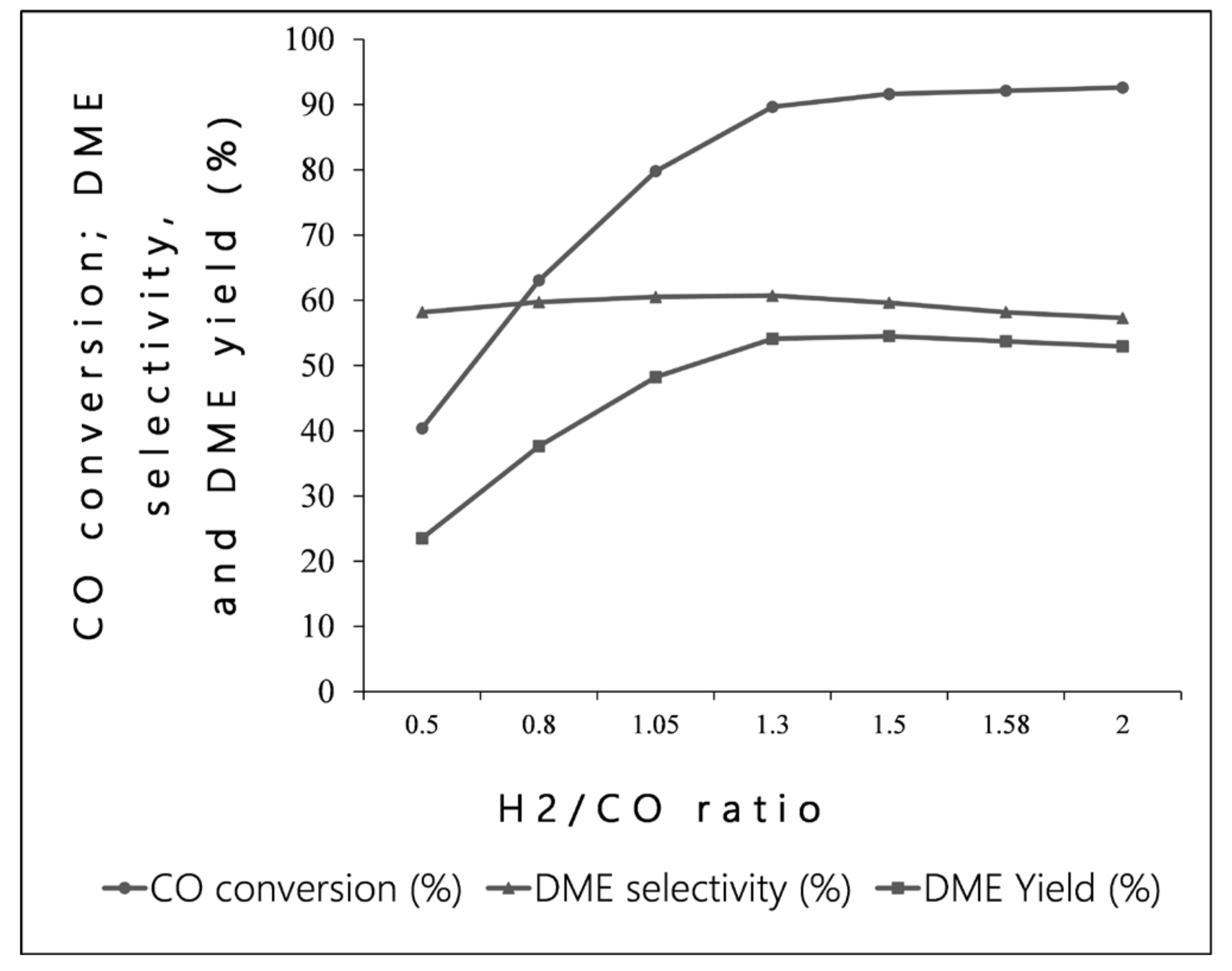
4.3. Effect of H2:CO Ratio

The variety of H2:CO ratio depends on the syngas preparing process, i.e., reforming and post-treatment. In this work, the change in the H2:CO ratio from 0.5 to 2 was implemented. Figure 8 illustrates the change in CO conversion, DME selectivity, and DME yield according to the change in H2:CO ratio. In the case of a low ratio, i.e., the low hydrogen concentration in the feed gas, methanol synthesis decreased. This affected the water–gas shift reaction rate. Consequently, the CO conversion, DME selectivity, and DME yield increased up to 1.3. A higher ratio did not have a significant influence, as seen in Figure 8. This observation could be explained based on the reaction mechanism. H2 takes part in two main reactions, methanol synthesis and reverse water–gas shift. Thus, when the H2: CO ratio is below 1, the generation of H2 is increased and encourages the CO conversion and CO2 conversion. As can be seen in Figure 8, when the ratio is more than 1, the slope of CO conversion and DME yield decrease, as the water–gas shift reaction rate is decreased. However, the reaction rate of methanol synthesis and dehydration is still higher than that of reverse water–gas shift. Therefore, the CO conversion and DME yield rise continuously. On the other hand, ratio higher than 1.3 resulted in higher water generation following methanol synthesis and decreased the efficiency of methanol dehydration. This leads to the decrease in DME mole flow rate, as shown in Figure 9. Moreover, Figure 9 shows that the range in ratio from 1.05 to 1.3 produced a similar DME mole flow rate while the maximum temperature value increased forward (see Supplementary Materials, Figure S7). The evidence suggests that the optimal ratio was 1.05.

4.4. Effect of CO2 Mole Fraction

CO2 is one of the factors which reduce DME synthesis efficiency. Therefore, most DME production plants investigate CO2 absorption to keep CO2 mole fraction in feed gas under 5%. However, the implementation of the CO2 absorbing section considerably increases the investment cost. This issue supports the sensitive analysis in case the feed flow varies from 5077 to 7031 Nm3/h while CO2 mole fraction was varied from 3 to 30%. Figure 10 illustrates the decline in CO conversion, DME selectivity, and DME yield. When CO2 accounts for 3% to 30% of feed gas composition, the CO conversion, DME selectivity, and DME yield decreased by 22.4, 56.1, and 65.1%, respectively. In addition, the flow rate of the DME outlet decreased by 23.4% while the methanol outlet flow rate increased by 92.4% (Figure 11). In contrast, the maximum temperature value declined from 330 to 300 °C when the CO2 mole fraction varied from 3 to 30% (see Supplementary Materials, Figure S8). This implies that the higher CO2 mole fraction could provide more safety operation; however, the decrease in DME selectivity and DME yield should be considered parallely.

5. Discussion

The fixed bed reactor is one of the most attractive reactors studied for the synthesis of DME. In this work, the mathematical model of fixed bed reactor with the hybrid catalyst was given for the one-step DME synthesis process. The 1D pilot-scale reactor model was investigated, including the reaction rate, and the heat and mass transfer behavior among catalyst, fluid, and shell/tube. The model, in terms of temperature profile and reactor performance indicator, such as, CO conversion, DME selectivity, and DME yield, was validated with experimental results measured at the pilot-scale unit. After the first operation of the pilot-scale reactor, we carried out troubleshooting to solve several problems such as leaks, inlet nozzle position, cracks of the catalysts, and so on. After the troubleshooting, we obtained nine steady-state experimental data sets under wide operating conditions during over one month. The comparison showed that this model was found to fit experimental data. The average errors were under 9.3% and under 8.1% for temperature test and reactor performance indicator, respectively. Through the comparision, we checked the reliability of the reactor model, and also explained the drawbacks of the reactor model, especially in terms of the temperature profiles and suggested ways to improve the reactor model. In the next step, the influence of major operating parameters, for instance, flow rate, feed pressure, H2:CO ratio in the feed gas, and CO2 mole fraction in the feed gas, were analyzed. A low feed flow rate, higher inlet pressure, higher H2:CO ratio, and lower CO2 mole fraction lead to higher CO conversion and DME yield. In the reactor, the lower feed flow rate can increase the residence time, and therefore, the total converted CO percentage increases. The rest of the factors affect the reactor performance via H2 concentration. The increase in feed pressure means the increase in H2 concentration and promotes methanol synthesis. The increase in H2:CO ratio accelerates methanol synthesis; however, it promotes a reverse water–gas shift reaction at the same time. The optimal ratio is 1.05. On the other hand, the large increase in CO2 mole fraction can discontinue the DME production since the increase in CO2 decreases the ratio of H2:CO. As the ratio gradually approaches 1, it favors the reverse water–gas shift reaction, which generates more water in the reactant mixture. Findings from this study strongly confirm the applicability and reliability of this model in DME synthesis plant design.

Supplementary Materials

The following are available online at https://www.mdpi.com/article/10.3390/catal11121522/s1, Table S1. Reaction rate equations, the equilibrium constant of each reaction and kinetic parameters, Table S2. The heat and mass transport property, Figure S1. Influence of the flow rate on the maximum temperature in the reactor, Figure S2. Influence of the feed pressure on (a) DME and (b) methanol mole flow at the outlet of the reactor, Figure S3. Influence of the feed pressure on the maximum temperature in the reactor, Figure S4. Influence of the H2 to CO ratio on the maximum temperature in the reactor, Figure S5. Influence of CO2 mole fraction on the maximum temperature in the reactor. Figure S6. Influence of the feed pressure on the maximum temperature in the reactor. Figure S7. Influence of the H2 to CO ratio on the maximum temperature in the reactor. Figure S8. Influence of CO2 mole fraction on the maximum temperature in the reactor.

Author Contributions

Conceptualization, D.S.; methodology, D.S.; software D.S., writing—review and editing D.S., S.Y.C., T.T.V., Y.H.P.D. and E.K.; funding acquisition, D.S., S.Y.C. All authors have read and agreed to the published version of the manuscript.

Funding

This research was conducted with the support of the National Research Foundation of Korea (NRF) grant funded by the Korea government (MSIT) (No. 2021R1F1A1048416).

Acknowledgments

This research was conducted with the support of the Graduate School of Chemical Characterization hosted by the Korean Ministry of Environment and the RFB project by the Ministry of Trade, Industry and Energy.

Conflicts of Interest

The authors declare no conflict of interest.

References

  1. Bayat, M.; Asil, A.G. Efficient in-situ water adsorption for direct DME synthesis: Robust computational modeling and multi-objective optimization. J. Nat. Gas Sci. Eng. 2020, 83, 103587. [Google Scholar] [CrossRef]
  2. Arcoumanis, C.; Bae, C.; Crookes, R.; Kinoshita, E. The potential of di-methyl ether (DME) as an alternative fuel for compression-ignition engines: A review. Fuel 2008, 87, 1014–1030. [Google Scholar] [CrossRef]
  3. Vakili, R.; Pourazadi, E.; Setoodeh, P.; Eslamloueyan, R.; Rahimpour, M.R. Direct dimethyl ether (DME) synthesis through a thermally coupled heat exchanger reactor. Appl. Energy 2011, 88, 1211–1223. [Google Scholar] [CrossRef]
  4. Semelsberger, T.A.; Ott, K.C.; Borup, R.L.; Greene, H.L. Generating hydrogen-rich fuel-cell feeds from dimethyl ether (DME) using physical mixtures of a commercial Cu/Zn/Al2O3 catalyst and several solid–acid catalysts. Appl. Catal. 2006, 65, 291–300. [Google Scholar] [CrossRef]
  5. Anggarani, R.; Wibowo, C.S.; Rulianto, D. Application of Dimethyl Ether as LPG Substitution for Household Stove. Energy Procedia 2014, 47, 227–234. [Google Scholar] [CrossRef] [Green Version]
  6. Shim, H.M.; Lee, S.J.; Yoo, Y.D.; Yun, Y.S.; Kim, H.T. Simulation of DME synthesis from coal syngas by kinetics model. Korean J. Chem. Eng. 2009, 26, 641–648. [Google Scholar] [CrossRef]
  7. Brunetti, A.; Migliori, M.; Cozza, D.; Catizzone, E.; Giordano, G.; Barbieri, G. Methanol Conversion to Dimethyl Ether in Catalytic Zeolite Membrane Reactors. ACS Sustain. Chem. Eng. 2020, 8, 10471–10479. [Google Scholar] [CrossRef]
  8. C.P. Consultants Private Ltd. Methanol and Di Methyl Ether Utilisation Isssues. 2016. Available online:https://dst.gov.in/sites/default/files/Final%20Survey%20Report%20DME%20Utilisation%20Sept%202.pdf (accessed on 26 November 2021).
  9. Rafiee, A. Staging of di-methyl-ether (DME) synthesis reactor from synthesis gas (syngas): Direct versus indirect route. Chem. Eng. Res. Des. 2020, 163, 157–168. [Google Scholar] [CrossRef]
  10. Parvez, A.M.; Mujtaba, I.M.; Hall, P.; Lester, E.H.; Wu, T. Synthesis of Bio-Dimethyl Ether Based on Carbon Dioxide-Enhanced Gasification of Biomass: Process Simulation Using Aspen Plus. Energy Technol. 2016, 4, 526–535. [Google Scholar] [CrossRef] [Green Version]
  11. Peral, E.; Martín, M. Optimal Production of Dimethyl Ether from Switchgrass-Based Syngas via Direct Synthesis. Ind. Eng. Chem. Res. 2015, 54, 7465–7475. [Google Scholar] [CrossRef]
  12. Azizi, Z.; Rezaeimanesh, M.; Tohidian, T.; Rahimpour, M.R. Dimethyl ether: A review of technologies and production challenges. Chem. Eng. Process. 2014, 82, 150–172. [Google Scholar] [CrossRef]
  13. Ham, H.; Kim, J.; Cho, S.J.; Choi, J.-H.; Moon, D.J.; Bae, J.W. Enhanced Stability of Spatially Confined Copper Nanoparticles in an Ordered Mesoporous Alumina for Dimethyl Ether Synthesis from Syngas. ACS Catal. 2016, 6, 5629–5640. [Google Scholar] [CrossRef]
  14. Stiefel, M.; Ahmad, R.; Arnold, U.; Döring, M. Direct synthesis of dimethyl ether from carbon-monoxide-rich synthesis gas: Influence of dehydration catalysts and operating conditions. Fuel Process. Technol. 2011, 92, 1466–1474. [Google Scholar] [CrossRef]
  15. Hosseini, S.; Taghizadeh, M.; Eliassi, A. Optimization of hydrothermal synthesis of H-ZSM-5 zeolite for dehydration of methanol to dimethyl ether using full factorial design. J. Nat. Gas Chem. 2012, 21, 344–351. [Google Scholar] [CrossRef]
  16. Catizzone, E.; Giglio, E.; Migliori, M.; Cozzucoli, P.C.; Giordano, G. The Effect of Zeolite Features on the Dehydration Reaction of Methanol to Dimethyl Ether: Catalytic Behaviour and Kinetics. Materials 2020, 13, 5577. [Google Scholar] [CrossRef]
  17. Catizzone, E.; Aloise, A.; Giglio, E.; Ferrarelli, G.; Bianco, M.; Migliori, M.; Giordano, G. MFI vs. FER zeolite during methanol dehydration to dimethyl ether: The crystal size plays a key role. Catal. Commun. 2021, 149, 106214. [Google Scholar] [CrossRef]
  18. Hosseininejad, S.; Afacan, A.; Hayes, R.E. Catalytic and kinetic study of methanol dehydration to dimethyl ether. Chem. Eng. Res. Des. 2012, 90, 825–833. [Google Scholar] [CrossRef]
  19. Mevawala, C.; Jiang, Y.; Bhattacharyya, D. Plant-wide modeling and analysis of the shale gas to dimethyl ether (DME) process via direct and indirect synthesis routes. Appl. Energy 2017, 204, 163–180. [Google Scholar] [CrossRef]
  20. Peng, X.-D. Kinetic Understanding of the Syngas-to-Dme Reaction System and Its Implications to Process and Economics; Air Products and Chemicals, Inc. (US): Allentown, PA, USA, 2002; 53p. [Google Scholar]
  21. Frusteri, F.; Migliori, M.; Cannilla, C.; Frusteri, L.; Catizzone, E.; Aloise, A.; Giordano, G.; Bonura, G. Direct CO2-to-DME hydrogenation reaction: New evidences of a superior behaviour of FER-based hybrid systems to obtain high DME yield. J. CO2 Util. 2017, 18, 353–361. [Google Scholar] [CrossRef]
  22. Frusteri, F.; Bonura, G.; Cannilla, C.; Drago Ferrante, G.; Aloise, A.; Catizzone, E.; Migliori, M.; Giordano, G. Stepwise tuning of metal-oxide and acid sites of CuZnZr-MFI hybrid catalysts for the direct DME synthesis by CO2 hydrogenation. Appl. Catal. 2015, 176–177, 522–531. [Google Scholar] [CrossRef]
  23. Cai, M.; Palčić, A.; Subramanian, V.; Moldovan, S.; Ersen, O.; Valtchev, V.; Ordomsky, V.V.; Khodakov, A.Y. Direct dimethyl ether synthesis from syngas on copper–zeolite hybrid catalysts with a wide range of zeolite particle sizes. J. Catal. 2016, 338, 227–238. [Google Scholar] [CrossRef] [Green Version]
  24. Mondal, U.; Yadav, G.D. Perspective of dimethyl ether as fuel: Part I. Catalysis. J. CO2 Util. 2019, 32, 299–320. [Google Scholar] [CrossRef]
  25. Brown, D.M.; Bhatt, B.L.; Hsiung, T.H.; Lewnard, J.J.; Waller, F.J. Novel technology for the synthesis of dimethyl ether from syngas. Catal. Today 1991, 8, 279–304. [Google Scholar] [CrossRef]
  26. Jun, G. Macro-kinetics study for synthesis of dimethyl ether from syngas in slurry reactor. Nat. Gas Chem. Ind. 2000, 25, 4–7. [Google Scholar] [CrossRef]
  27. Li, Z.; Zuo, Z.; Huang, W.; Xie, K. Research on Si–Al based catalysts prepared by complete liquid-phase method for DME synthesis in a slurry reactor. Appl. Surf. Sci. 2011, 257, 2180–2183. [Google Scholar] [CrossRef]
  28. Ereña, J.; Garoña, R.; Arandes, J.M.; Aguayo, A.T.; Bilbao, J. Effect of operating conditions on the synthesis of dimethyl ether over a CuO-ZnO-Al2O3/NaHZSM-5 bifunctional catalyst. Catal. Today 2005, 107–108, 467–473. [Google Scholar] [CrossRef]
  29. Lu, W.-Z.; Teng, L.-H.; Xiao, W.-D. Simulation and experiment study of dimethyl ether synthesis from syngas in a fluidized-bed reactor. Chem. Eng. Sci. 2004, 59, 5455–5464. [Google Scholar] [CrossRef]
  30. Yousefi, A.; Eslamloueyan, R.; Kazerooni, N.M. Optimal conditions in direct dimethyl ether synthesis from syngas utilizing a dual-type fluidized bed reactor. Energy 2017, 125, 275–286. [Google Scholar] [CrossRef]
  31. Mondal, U.; Yadav, G.D. Perspective of dimethyl ether as fuel: Part II—Analysis of reactor systems and industrial processes. J. CO2 Util. 2019, 32, 321–338. [Google Scholar] [CrossRef]
  32. Ghavipour, M.; Behbahani, R.M. Fixed-bed reactor modeling for methanol to dimethyl ether (DME) reaction over γ-Alumina using a new practical reaction rate model. J. Ind. Eng. Chem. 2014, 20, 1942–1951. [Google Scholar] [CrossRef]
  33. Farsi, M.; Jahanmiri, A. Enhancement of DME Production in an Optimized Membrane Isothermal Fixed-Bed Reactor. Int. J. Chem. React. Eng. 2011, 9, 1–13. [Google Scholar] [CrossRef]
  34. Song, D.; Cho, W.; Lee, G.; Park, D.K.; Yoon, E.S. Numerical Analysis of a Pilot-Scale Fixed-Bed Reactor for Dimethyl Ether (DME) Synthesis. Ind. Eng. Chem. Res. 2008, 47, 4553–4559. [Google Scholar] [CrossRef]
  35. Chung-Sung Tan, D.-C.L. Axial Dispersion of Supercritical Carbon Dioxide in Packed Beds. Ind. Eng. Chem. Res. 1989, 28, 1246–1250. [Google Scholar] [CrossRef]
  36. Lei, K.; Ma, H.; Zhang, H.; Ying, W.; Fang, D. Study on Effective Radial Thermal Conductivity of Gas Flow through a Methanol Reactor. Int. J. Chem. React. Eng. 2015, 13, 103–112. [Google Scholar] [CrossRef]
  37. Tronconi, E.; Groppi, G.; Boger, T.; Heibel, A. Monolithic catalysts with ‘high conductivity’ honeycomb supports for gas/solid exothermic reactions: Characterization of the heat-transfer properties. Chem. Eng. Sci. 2004, 59, 4941–4949. [Google Scholar] [CrossRef]
  38. Bussche, K.V.; Froment, G. A Steady-State Kinetic Model for Methanol Synthesis and the Water Gas Shift Reaction on a Commercial Cu/ZnO/Al2O3 Catalyst. J. Catal. 1996, 161, 1–10. [Google Scholar] [CrossRef]
  39. Gorazd, B.; Janez, L. Intrinsic and global reaction rate of methanol dehydration over γ-alumina pellets. Ind. Eng. Chem. Res. 1992, 31, 1035–1040. [Google Scholar] [CrossRef]
  40. Twigg, M.V. Catalyst Handbook, 2nd ed.; John Wiley & Sons: New York, NY, USA, 1996. [Google Scholar]
  41. Daniel, R.S.; Edgar, F.W.; Gerard, C.S. The Chemical Thermodynamics of Organic Compounds; John Wiley: New York, NY, USA, 1969. [Google Scholar]
  42. Ng, K.L.; Chadwick, D.; Toseland, B.A. Kinetics and modelling of dimethyl ether synthesis from synthesis gas . Chem. Eng. Sci. 1999, 54, 3587–3592. [Google Scholar] [CrossRef]
  43. Çengel, Y.A. Heat Transfer: A Practical Approach; WBC McGraw-Hill: Boston, MA, USA, 1998. [Google Scholar]
  44. Welty, J.R. Fundamentals of Momentum, Heat and Mass Transfer; Wiley: Hoboken, NJ, USA, 2013; ISBN 2 1118804295. [Google Scholar]
  45. McCabe, W.L.; Smith, J.C.; Harriott, P. Unit Operations of Chemical Engineering; McGraw-Hill: New York, NY, USA, 1993; Volume 5. [Google Scholar]
  46. Daesung, S. Modeling and Simulation of Dimethylether Synthesis Reactor; Seoul National University: Seoul, Korea, 2010. [Google Scholar]
  47. Giglio, E.; Pirone, R.; Bensaid, S. Dynamic modelling of methanation reactors during start-up and regulation in intermittent power-to-gas applications. Renew. Energy 2021, 170, 1040–1051. [Google Scholar] [CrossRef]
Figure 1. (a) The pilot fixed bed reactor; (b) reactor model.
Catalysts 11 01522 g001
Figure 2. Simulated temperature profile and experimental data along the reactor length.
Catalysts 11 01522 g002
Figure 3. Calculated temperature and experimental temperature at 3 points (0.015 m, 0.515 m, and 1.015 m).
Catalysts 11 01522 g003
Figure 4. Parity plots for fractional (a) CO conversion, (b) DME selectivity, and (c) DME yield.
Catalysts 11 01522 g004
Figure 5. Influence of the flow rate on CO conversion, DME selectivity, and DME yield.
Catalysts 11 01522 g005
Figure 6. Influence of the flow rate on DME mole flow at the outlet of the reactor.
Catalysts 11 01522 g006
Figure 7. Influence of the feed pressure on CO conversion, DME selectivity, and DME yield.
Catalysts 11 01522 g007
Figure 8. Influence of the H2 to CO ratio on CO conversion, DME selectivity, and DME yield.
Catalysts 11 01522 g008
Figure 9. Influence of the H2 to CO ratio on (a) DME and (b) methanol mole flow at the outlet of the reactor.
Catalysts 11 01522 g009
Figure 10. Influence of CO2 mole fraction on CO conversion, DME selectivity, and DME yield.
Catalysts 11 01522 g010
Figure 11. Influence of CO2 mole fraction on (a) DME and (b) methanol mole flow at the outlet of the reactor.
Catalysts 11 01522 g011
Table 1. Properties of the catalyst and information on the pilot-scale reactor in a trial.
ReactorInner diameter of a tube (m)0.02972
Outside diameter of a tube (m)0.0381
Inner diameter of shell side (m)0.2
Tube number7
Tube length (m)1.5
CatalystTotal weight (kg)8
Weight of a catalyst (g)0.215
Diameter of a catalyst (m)0.004
Height of a catalyst (m)0.005
Composition of a catalyst
(CuO/ZnO/Al2O3 + additive: γ -Alumina)
(7:3)
Table 2. The data set of pilot-plant operation parameters.
Data1Data2Data3Data4Data5Data6Data7Data8Data9
Feed temperature (°C)210210205210210210205210210
Reactor pressure (bar)404748423844374141
Feed flow (Nm3/h)28.1228.136.5625.2725.639.3728.025.3125.3
Average temperature of cooling water (°C)200200210210210215210200220
Feed composition (mol %)
H246.9446.948.7348.0553.5148.8445.4044.4844.4
CO43.7143.745.3744.7441.1845.4748.8148.0348.11
CO26.096.093.317.063.03.832.234.454.43
CH40.140.190.170.150.130.150.160.180.18
DME0.410.441.5501.371.111.781.811.83
Methanol0.240.210.8700.800.601.621.061.06
Table 3. Properties of the catalyst and information on the demo-plant scale reactor.
ReactorInner diameter of a tube (m)0.02858
Outside diameter of a tube (m)0.032898
Inner diameter of shell side (m)1.6
Tube number902
Tube length (m)6 (5.4)
CatalystTotal weight (kg)2082.4
Weight of a catalyst (g)0.215
Diameter of a catalyst (m)0.004
Height of a catalyst (m)0.005
Composition of a catalyst
(CuO/ZnO/Al2O3 + additive: γ-Alumina)
(65:30), Graphite 5%
Publisher’s Note: MDPI stays neutral with regard to jurisdictional claims in published maps and institutional affiliations.

