Article

Process Intensification of Methane Production via Catalytic Hydrogenation in the Presence of Ni-CeO2/Cr2O3 Using a Micro-Channel Reactor

by
Vut Tongnan
1,
Youssef Ait-lahcen
2,
Chuthamas Wongsartsai
1,
Chalempol Khajonvittayakul
1,
Nuchanart Siri-Nguan
3,
Navadol Laosiripojana
4 and
Unalome Wetwatana Hartley
1,4,*
1
Chemical and Process Engineering, The Sirindhorn International Thai-German Graduate School of Engineering (TGGS), King Mongkut’s University of Technology North Bangkok, Bangkok 10800, Thailand
2
Process Engineering, National Polytechnic Institute of Chemical Engineering and Technology, 4 Allee Emile Monso, 31030 Toulouse, France
3
PTT Public Company Limited, Ayutthaya 10908, Thailand
4
Joint Graduate School of Energy and Environment (JGSEE), King Mongkut’s University of Technology Thonburi, Bangkok 10140, Thailand
*
Author to whom correspondence should be addressed.
Catalysts 2021, 11(10), 1224; https://doi.org/10.3390/catal11101224
Submission received: 2 September 2021 / Revised: 28 September 2021 / Accepted: 5 October 2021 / Published: 11 October 2021
(This article belongs to the Special Issue Modern Catalytic Reactor: From Active Center to Application Tests)

Abstract

:
A slight amount of Cr2O3 segregation in 40 wt% NiO/Ce0.5Cr0.5O2 was presented at the surface. The best catalytic performance towards the reaction was achieved at 74% of CO2 conversion and 100% CH4 selectivity at 310 °C, the reactant (H2/CO2) feed molar ratio was 4, and the WHSV was 56,500 mlN·h−1·g−1cat. The mechanistic pathway was proposed through carbonates and formates as a mediator during CO2 and H2 interaction. Activation energy was estimated at 4.85 kJ/mol, when the orders of the reaction were ranging from 0.33 to 1.07 for nth-order, and 0.40 to 0.53 for mth-order.

1. Introduction

CO2 is one of the greenhouse gases (GHGs), well-known for causing the climate change and global warming. This study proposes CO2 conversion to methane via CO2 hydrogenation or the so-called methanation process. The reaction generally occurs at moderately a high temperature ranging from 250 to 400 °C [1] associated with the reverse water gas shift (RWGS) reaction [2]. Ni-doped high porous supports were extensively studied for such a process during the past decades. Ni/SiO2 prepared using metal-organic framework (MOF) derivatives were studied by Ye et al., (2021) [3]. It was reported that the nickel phyllosilicate, formed by bonding between Ni and silicate enhanced the stability of the catalyst towards the reaction. The catalyst offered 77.2% of CO2 conversion and 100% CH4 selectivity; at 310 °C, under 20 bar, within 52 h of reaction time (T50 = 270 °C). Atzori et al., (2019) [4] synthesized 25% Ni/CeO2–ZrO2 (3:1 ratio of CeO2/ZrO2) using the soft-template method which was found to provide even better catalytic performance compared with the Ni/SiO2. The catalyst provided 85% CO2 conversion and 100% CH4 selectivity at a relatively lower operating temperature of 300 °C, after running for 6 h (T50 = 260 °C). From this study, it was suggested that CO2 adsorption occurred on CeO2/ZrO2, whereas gaseous H2 reacted with the active Ni species. The effect of Ni content and the choice of supports in the catalyst system were studied by Gac et al., (2019) [5], where the level of Ni varied from 10 to 40% by weight on various supports, i.e., CeO2, ZrO2, and Al2O3. It was reported that the optimal Ni loading was between 20 and 30% at T50 = 250 °C, whereas the activity of the catalyst system, when using a different support, was ordered as Al2O3 < ZrO2 < CeO2. The number of Ni active surfaces is basically increased by the higher Ni doping level; however, the Ni agglomeration often occurs when the Ni level is more than 30%, resulting in a drop in the number of Ni active surfaces. Nevertheless, this is not the case when using Al2O3 as a support due to its relatively high surface area. Despite its excellent ability to disperse Ni and its high thermal stability, Al2O3 as a support, offered a lower synergy effect in terms of catalytic activity of the overall catalyst system, compared with the study by Ceria-Zirconia Bukhari et al., (2019) [6] who added Ni at 1, 3, 5, and 10 wt% into fibrous SBA-15, to investigate the effect of Ni loading. The result showed that 5% Ni/fibrous SBA-15 provided the best activity amongst all with 98.9% CO2 conversion and 99.6% CH4 selectivity at 400 °C for 120 h. This was due to some specific characteristics of the catalyst system which include (1) homogeneous and well-dispersed Ni particles on the support, (2) strong metal-support interaction, and (3) high surface basicity. However, when the catalytic activity was found to decrease when the Ni loading was higher than 10% due to the agglomeration as explained earlier. Jaffar et al., (2019) [7] studied the effect of various parameters, i.e., temperature, gas hourly space velocity (GHSV), H2:CO2 ratio, choice of metals (Ni, Fe, Co, and Mo) and the type of supports (Al2O3, SiO2 and MCM-41) on the methanation process via CO2 hydrogenation. The 10% Ni/Al2O3 was found to provide the highest CO2 conversion of 83% and CH4 yield of 94% at 360 °C, amongst all the studied catalysts. The zeolitic supports, i.e., SiO2 and MCM-41, were not reported as the most promising material due to its hydrophilicity. In this phenomena, Si-O-Si would be formed on the surface via H2O (byproduct) adsorption, favoring water gas shift (WGS) reaction. This resulted in a decrease in CH4 yield and an increase in CO formation. Besides, the carbonyl surface species formation (on the zeolitic supports) can be inhibited by water surface coverage. The influence of different preparation methods for NiO-CeO2 was also studied by Cárdenas-Arenas et al. (2020) [8]. The results showed that the reversed micro-emulsion method provided the best activity in terms of CO2 conversion (80%) and CH4 yield (98%) at 400 °C for 25 h (T50 = 300 °C), due to its highest specific surface area (122 m2/g), small crystal size (6–7 nm), and highly reducible Ni-O-Ce species on the surface. Bi-metallic catalysts have been excessively researched recently [9,10,11]. The effect of different types of promoters, i.e., Zr, Ce, La, and Mo, has been studied [9,10]. Although La was reported to offer sufficient catalytic activity (83% CH4 yield at 300 °C (T50 = 265 °C)), due to its high basicity, allowing strong CO2 adsorption; however, Ce was able to provide the better catalytic performance (CO2 conversion of 76.4% and CH4 selectivity of 99.1% at 350 °C for 10 h (T50 = 240 °C)). In addition, the TOF value of CeO2 was found to be the highest amongst the selected promoters; thus, it can generate more active sites, resulting in an increase in the catalyst’s intrinsic rate. The observation from many previous works reported that the activity of CO2 methanation is generally increased with temperature; however, CH4 selectivity would be halted once it reached a certain limit. The catalyst deactivation is observed during high temperature operation, due to the catalyst sintering. The CH4 selectivity is usually encouraged at a relatively low operating temperature; however, the reaction occurs at a low kinetic rate, since the kinetic rate of a certain reaction can be enhanced by an optimal design of reactor. Thus, to optimize the catalytic performance of the methanation process is to maintain the high CO2 methanation as well as the high CH4 selectivity. Therefore, the process intensification becomes another crucial concern, rather than the sole development of the catalysts. A micro-reactor or micro-channel reactor can the enhance overall performance of a particular chemical reaction process, due to its small residence time, low mass/heat transfer limitation, narrowed product distribution and rapid responding behavior [12,13,14].
The micro-channel catalytic reactors were proven to increase productivity compared with other similar-sized conventional reactors [1], due to higher catalyst surface-to-volume ratios. Besides, a catalyst in a micro-channel reactor is generally applied by using a wall-coating technique. This means that there is no concerned pressure drop across the catalyst’s bed, unlike in the conventional packed-bed reactor [15]. In the meantime, catalyst selection is still one of the most crucial issues for the process development. The right catalyst increases the desired products by reducing their reaction’s activation energies, while also hindering the unwanted side reactions. These actions lead to the elimination of thermodynamic limitation, and less complication in a post-reaction-separation unit due to its narrower product distribution.
The methanation catalysts generally consist of two parts: (1) transition/noble metal, i.e., Ni, Fe, Co, Ru or Pd, acts as an active site [2]; and (2) (mixed) metal oxide, i.e., Al2O3, SiO2, ZrO2, CeO2, La2O3, MgO, TiO2, carbon materials and zeolites, act as a support [12,13]. CeO2 was chosen as a support in the present work because of its outstanding oxygen storage capacity and its ability to promote the active metal dispersion [14]. Besides, the oxygen vacancy of CeO2 can be tailored to needs by substituting the smaller transition metal ion (compared with Ce) into it such as Zr4+ or Cr3+ [16]. The high oxygen vacancy material is well-known to improve its acidic/basic catalytic properties for CO/CO2 adsorption capability [15,17]. Several previous studies reported that CeO2/Cr2O3 established higher oxygen vacancy than CeO2/ZrO2 [18,19]. Vannice et al. (1977) [2] compared the activities of group VIII metals that were dispersed on Al2O3. The result showed that the order of the activity ranked from high to low as Ru >> Fe > Ni > Co > Rh > Pd > Pt > Ir. Although Ru is superior, its cost is high. Fe or Ni therefore received greater attention due to its reasonable price and sufficient catalytic activity. Nie et al. (2017) [20] studied Ni content by varying percentage of Ni, which was doped on Ce0.9Zr0.1O2, from 10 to 40%. It was found that CO2 conversion reached its maximum at 95% when Ni level was 40%. According to our previous work [21], Ni doped on CexCr1-xO2 of which the stoichiometric ratio (x) was 0.5, is one of the superior catalyst supports for simultaneously maximizing CO2 conversion and CH4 selectivity. In this work, 40% Ni-CeO2/Cr2O3 was prepared using the one-pot hydrolysis method. The catalyst was wash-coated inside a stainless-steel micro-channel reactor. Physicochemical properties of the catalyst were investigated using an X-ray diffractometer (XRD), hydrogen temperature-programmed reduction (H2-TPR), and Fourier-transform infrared spectroscopy (FTIR). The effect of operating parameters on the catalytic performance was investigated. The mechanism of the gas-solid reaction and kinetics were also predicted.

2. Results and Discussion

2.1. Characterizations
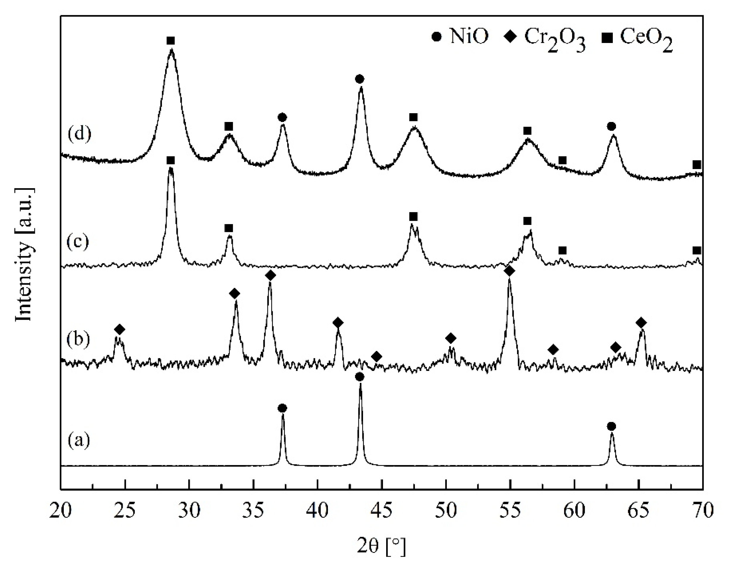
2.1.1. XRD

Figure 1 compares XRD patterns between the catalyst 40% Ni-CeO2/Cr2O3 (1:1) catalyst (d) and the pure NiO (a), Cr2O3 (b), CeO2 (c). The catalyst diffractogram resembled the CeO2 phase structure, identified at 28.64, 33.16, 47.61, 56.32, 59.02, and 69.45; whereas the NiO phase was found at 37.30, 43.34, and 62.92 (JCPDS No. 01-078-0429). However, no Cr2O3 phase (2θ at 24.57, 33.53, 36.34, 41.58, 44.60, 50.37, 54.93, 58.35, 63.20, and 65.18 with JCPDS card No. 38-1479) was detected in the catalyst’s diffractogram, implying that Cr was substituted into the Ce lattice with none or little segregation of Cr to the catalyst surface. This can be due to the fact that the ionic radius of 3D transition metal is smaller than the cerium ions radius (0.615 Å for Cr3+ versus 1.01 Å for Ce4+ [16]). The CeO2 peaks shown in the catalyst’s diffractogram were slightly shifted to a higher degree, compared with the pure CeO2 which were positioned at 28.54, 33.12, 47.34, 56.20, 58.92, and 69.30 (JCPDS card No. 03-065-5923). This was due to the substitution of a smaller Cr ion into the CeO2 lattice, creating a larger channel radius in the lattice and high oxygen mobility [22] while the fluorite structure was remained. The NiO peak in the catalyst was seen to be broader than that in pure NiO (a), indicating that the NiO in the catalyst system has a smaller particle size, resulting in good dispersion of Ni on the CeO2/Cr2O3. This result agreed with TPR results in the later section.

2.1.2. H2-TPR

The catalyst reducibility was studied by the temperature programmed reduction (TPR) technique using 5% H2/Ar. In Figure 2, it can be seen that for pure NiO (a), two distinct peaks were observed and centered at 380 °C (peak α) and 500 °C (peak β), attributing to a reduction in Ni2+ ions to metallic Ni at the surface and bulk oxygen, respectively. This result agreed with the work reported by other researchers [23]. The TPR spectrum of the catalyst (b) showed three reduction peaks. The first peak (peak α) was due to reduction in NiO, which occurred at 310 °C, and lower than the reduction temperature of pure NiO. This indicates good dispersion of NiO on the CeO2/Cr2O3 [24], which resulted from the smaller particle size of Ni at the surface. The strong bonding interaction between NiO and the support (CeO2/Cr2O3) was suggested, as the peak β of the catalyst was found at a higher temperature compared with that of pure NiO [24]. The peak γ of the catalyst was found at a temperature higher than 900 °C. This peak is the result of NiCr2O4 spinel [25] or CeCrO3 perovskite [26] which were formed via NiO + Cr2O3 → NiCr2O4 or 2Ce0.5Cr0.5O2+δ → CeCrO3 + (0.5 + δ)O2, indicating that a slight amount of Cr2O3 presented at the surface; however, it was not sufficient to be detected by XRD.

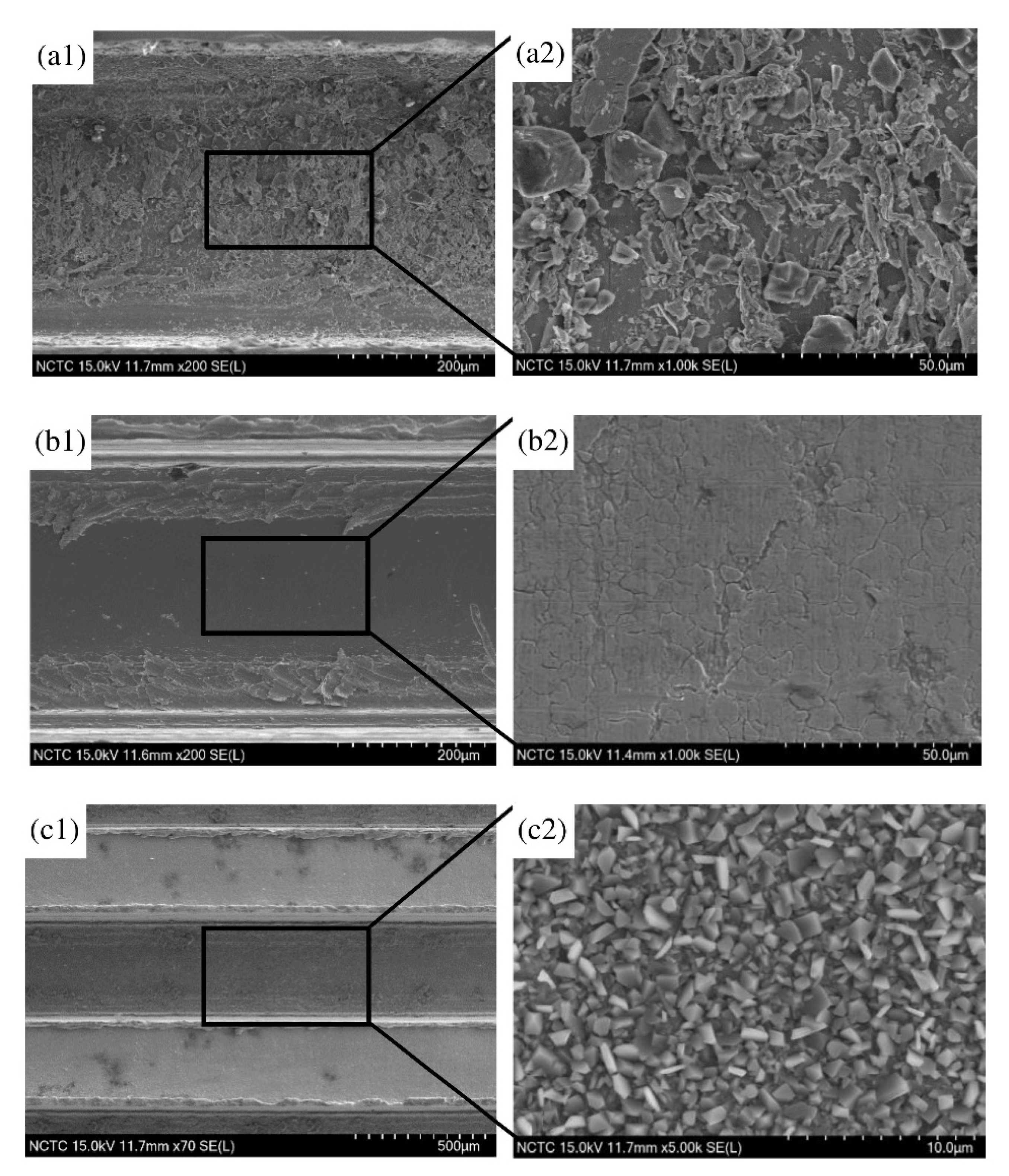
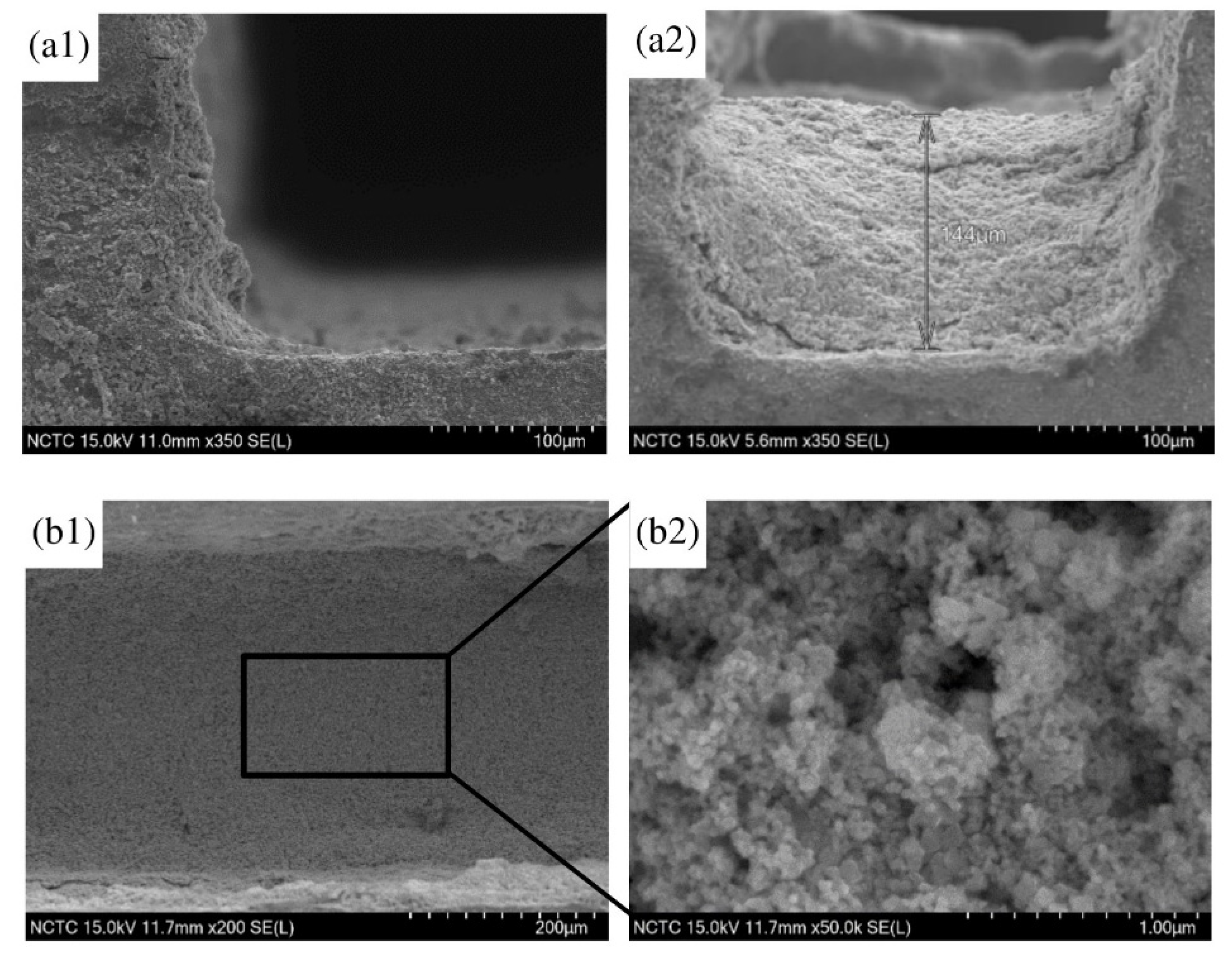
2.1.3. SEM Morphology before and after Catalyst Coating

The SEM images of the substrates were observed as shown in Figure 3: where Figure 3(a1) and Figure 3(a2) represent the surface before the cleansing process; Figure 3(b1) and Figure 3(b2) are for the surface after the cleansing process; and Figure 3(c1) and Figure 3(c2) demonstrate the substrate’s surface after the cleansing and annealing process. The surface appeared smoother after the cleansing process. After the annealing process, images of the grains could be seen. This was suspected to be a layer of mixed oxides, formed by the oxidation process of oxygen and the metal components in the stainless steel such as Ni, Cr and Fe. The mixed metal oxides can enhance the surface roughness and establish better chemical adhesion of the surface with the coating catalyst.
Figure 4 illustrates the morphologies of the coated surface after the wash-coat process. The thickness of catalyst was determined at 144 µm. The catalyst layer was seen as uniformly scattered and homogeneous along the channel. Figure 4(b2) demonstrates micro-sized particles with different distribution of macro-pore.

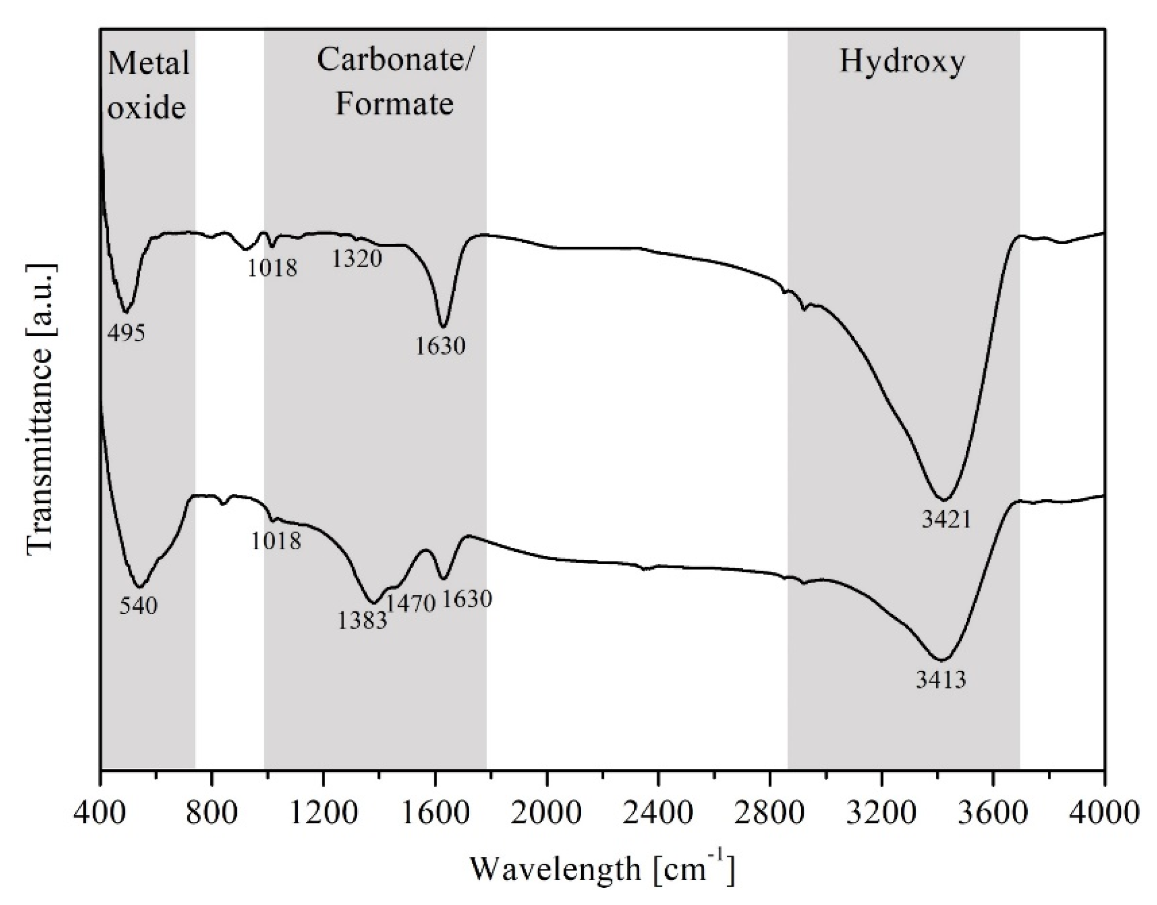
2.1.4. FTIR Spectroscopy before and after Exposure to Reaction

FTIR spectroscopy was applied to identify the adsorbed functional species on the catalyst when being exposed in the gaseous reactant stream, CO2 + H2, at 270 °C. Figure 5 demonstrates the adsorbed species of the pre- (top) and post-exposure (bottom) catalyst. The deepest strong band at 3413–3421 cm−1 is ascribed to the O–H stretching vibration in OH groups, due to from adsorbed water and/or H-chemisorbed atom on metal. The bridged bidentate carbonate species was banded at 1630 cm−1, 1320 cm−1, and 1018 cm−1, assigned to the asymmetric, symmetric CO3-stretching, and OCO-bending (νas(CO3), νs(CO3), and δ(OCO), respectively, as a vibration mode), which appeared in both pre- and post-exposure catalysts. While the carbonate species of the fresh catalyst were likely to be the result of an uncompleted combustion process during the calcination (in static air at 500 °C for 12 h at 10 °C·min−1 of heating rate), those in the spent catalyst were suspected to indicate the CO2 adsorption.
Importantly, the bands located at 1383 and 1470 cm−1, which are assigned to the CH–bending and asymmetric CO2-stretching (δ(CH) and νas(COO) as a vibration mode), are attributed to formate species, according to chelating bidentate.
In addition, the bending vibration of NiO bonding was indicated at a wavelength ranging from 495 to 540 cm−1 [27]. These results indicated that the carbonates and formates are the intermediates for the methanation via CO2 hydrogenation. The mechanism of CO2 hydrogenation in the presence of Ni-CeO2/Cr2O3 is proposed as schematically shown below in Figure 6:

2.2. Catalytic Activity of NiO-Ce0.5Cr0.5O2 towards CO2 Methanation

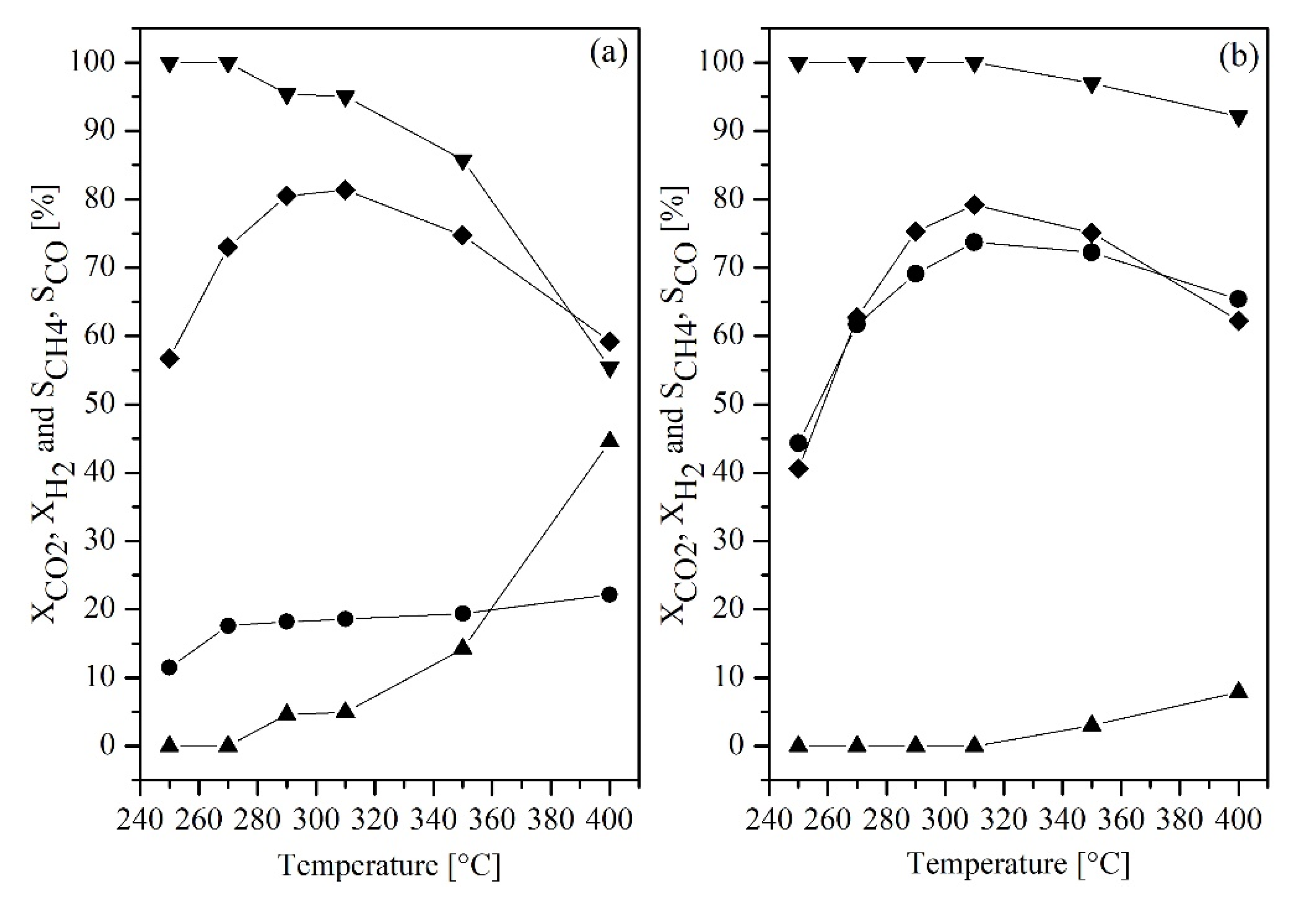
2.2.1. Effect of Molar Feed Ratio vs. Temperature

From Figure 7, it can be seen that CO2 conversion was increased when the amount of hydrogen was increased (or ratio of H2 to CO2 was changed from 2:1 to 4:1) (Figure 7a), indicating that the CO2 was excess in the first case (Figure 7a). CH4 selectivity was found to increase when the percentage of H2 in the feed reactant increased (Figure 7b), meaning that the H2 is the limiting agent when the H2 to CO2 ratio was 2 to 1 (Figure 7a) (the similar trend was observed by Abbelo et al. (2013) [28] and Rahmani et al. (2014)) [29], where the increasing ratio of H2/CO2 would cause an increase in CO2 conversion, as the reaction was promoted by a high concentration of dissociated hydrogen on the catalyst surface [29,30,31]. The results agreed with work reported by Daroughegi et al. (2017) [30], which stated that the stoichiometric ratio of H2/CO2 should be equaled 4.0 due to the basicity property on the nickel’s surface species. This means that four molecules of H2 are required to suppress CO2 adsorption on active of the catalyst since the H2 molecule can be entirely adsorbed on the catalyst’s surface, which simultaneously has much more hydrogenate on the carbonate species.
In addition, it can be seen that in the reverse water gas shift (RWGS) reaction, (CO2 + H2 ↔ CO + H2O) was more promoted at the lower ratio of H2/CO2, which resulted in a decrease in CH4 selectivity. By temperature range, the conversions were found to increase during the operating temperature ranging from 250 to 310 °C. Decreases in conversions and product selectivity were due to the occurring of RWGS reaction which is thermodynamically favorable at a higher temperature. The optimal temperature was determined to be at 310 °C for both ratios, providing CO2 conversion and CH4 selectivity at 18.57% and 95.06% for (2:1 ratio) and at 73.75% and 100% for (4:1 ratio), respectively. This result agreed with the H2-TPR result which reported peak α centered at 310 °C.
Table 1 compares catalytic performance of the catalyst from this work tested in a micro-channel reactor, with other recent catalysts developed tested in a packed-bed reactor by other researchers. The 40 wt% Ni-CeO2/Cr2O3 catalyst in a micro-channel reactor was found to possess the best performance at a lower operating temperature, even at the higher WHSV.

2.2.2. Kinetic Measurement

The kinetic parameters of CO2 methanation in the presence of 40 wt% Ni-CeO2/Cr2O3 was studied in a micro-channel reactor at temperature ranging from 250 to 280 °C. The parameters calculation was performed using the POLYMATH 6.10 Software. The temperature range was selected based on the minimal side reactions and its initial reaction-controlled regime. The ratio of H2 to CO2 was varied at 1:1, 1:2, and 4:1. The power-law rate expression, as described in Equation (4), was applied to fit the rate of CO2 methanation. A simple rate equation was considered due to the fact that the rate of the reaction changes with the change in concentration of each reactant, whereas the concentration changes on the catalyst’s surface was ignored. Therefore, the overall reaction rate for the irreversible reaction is focused only on the reactants:
r C O 2 = r H 2 = d [ C O 2 ] d t = d [ H 2 ] d t = k ( T ) [ H 2 ] n [ C O 2 ] m
where −rCO2 and −rH2 are the reaction rate in mol·L−1·s−1, [CO2] and [H2] in mol·L−1 are molar concentration of each species, k is the reaction rate constant with dependence on the temperature, n and m are the reaction order with respect to CO2 and H2.
The rate constant, which describes the temperature dependency of the reaction rate, is assumed to obey the Arrhenius relationship according the following equation:
ln k ( T ) = E a ( 1000 / R T ) + ln k 0
The negative apparent activation energy (Eapp), achieved from the Arrhenius plots as illustrated in Figure 8, was determined at 4.85 kJ·mol−1. The orders of the reaction with respect to H2 and CO2 were estimated at 0.33 to 1.07 for nth-order and 0.40 to 0.53 for mth-order. The apparent activation energy was benchmarked with other previous works as shown in Table 2.

3. Methodology

3.1. Pre-Treatment of Micro-Channel Reactor

A micro-channel reactor was fabricated from two micro-structured stainless steel (316 L) plates, laser welded together by the Thai German Institute (TGI) (Chonburi, Thailand). Each plate accommodated 14 channels with dimensions of 25 mm in length, 0.37 mm in width, and 0.30 μm in depth. The gaseous inlet was assumed to be uniformly distributed amongst the 14 slots by 3 physical dots, locating at the corners of an isosceles triangle. The steps of micro-channel pre- and post-treatment was prepared as illustrated in Figure 9, where (a) is the specimens before cleansing, (b) is after cleansing with citric acid, and (c) is after annealing at 800 °C. During the cleansing process, the plates were cleaned by immersing in citric acid (20% by volume) in an ultrasonic bath for 5 h (step 1) before being rinsed by deionized water (step 2). In order to generate grains of mixed oxides on the surface, the micro-channel plates were then annealed at 800 °C for 10 h with 1 °C·min−1 of heating rate risen from room temperature (step 3). Finally, the two plates were laser-welded together after completing the catalyst coating process, described in the next section.

3.2. Catalyst Coating on the Micro-Channeled Substrates

3.2.1. Catalyst Powder Preparation

Ni-CeO2/Cr2O3 was synthesized using the one-pot hydrolysis method described elsewhere [20]. The percentage of Ni was 40% by weight with a ratio of CeO2 to Cr2O3 at 1 to 1. The stoichiometric amount of the relevant nitrate precursors: (Ni(NO3)2.6H2O (CARLO ERBA, ≥99.0%); Ce(NO3)3·6H2O (ALDRICH, ≥99.0%); Cr(NO3)2·6H2O (ACROS, ≥99.0%): were dissolved together in 100 mL demineralized water. The mixture was then heated to 80 °C while stirred continuously. Ammonium carbonate (NH4)2CO3 solution (1 M) was added the drop-wise into the previous mixture to maintain the solution pH at 8.8 to 9.0, while the mixed solution was heated to 120 °C, to evaporate water. The residual was afterwards calcined in static air at 500 °C for 12 h at 10 °C·min−1 heating rate. The resulting catalyst powder was ground and sieved to achieve the particle size of 35 µm or smaller.

3.2.2. Catalyst Suspended Solution Preparation

This method was adapted from a procedure previously described elsewhere [50]. The mass ratio of Ni-CeO2/Cr2O3:H2O:PVA:CH3COOH was fixed at 10:84:5:1 in this study. Polyvinyl alcohol (PVA) solution, as a binder, was prepared beforehand by dissolving in deionized water under vigorous stirring at 65 °C for 2 h before being left overnight without stirring. The sieved catalyst was dispersed into the binder solution under a vigorous stirring condition. Acetic acid (CH3COOH, 17 M) was added into the solution while being heated to reach the temperature of 65 °C where it remained for 2 h. After the well-mixed solution was naturally cooled down to room temperature, the stirring was continued for 3 days.

3.2.3. Wash-Coat

The prepared catalyst suspension was wash-coated onto the surface of the micro-structured substrates. The plates were left at room temperature for 4 h before they were dried in an oven at 120 °C overnight. The excess polymer binder was eliminated by a calcination process at 500 °C for 3 h. Approximately 32 mg of the catalyst were successfully coated on the surface of each plate after two times of coating.

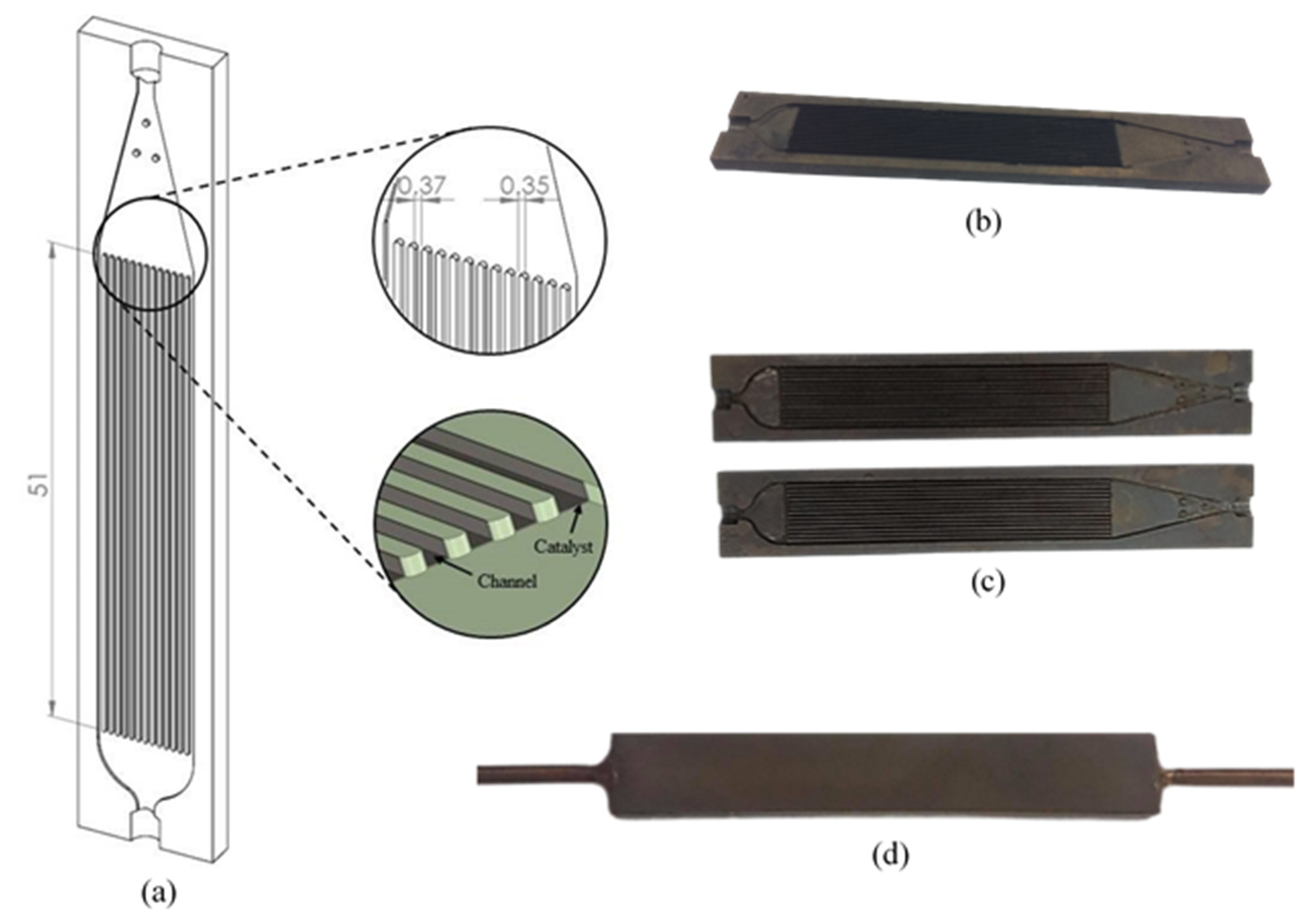
3.2.4. Micro-Channel Reactor Fabrication

Two of the coated plates were laser-weld together. Figure 10 illustrates the configuration of the micro-channel reactor. The adhesion between the catalyst and surface of the substrates were tested using a drop test [20]. Both ends of the micro-channel reactor were connected with 1/8-inch stainless steel tubes by welding. To ensure there was no leakage, the following was performed: (i) one end of the reactor was clogged with a plug, (ii) inert gas was compressed through the reactor at 5 bar, (iii) the reactor was immersed into water, and (iv) a leakage can be regarded if air bubbles are noticed.

4. Characterizations

An X-ray diffractometer (Bruker AXS, Berlin, Germany, Diffractometer D8 equipment using CuKα (λ = 1.5418 Å) as a radiation source at 40 kV and 30 mA with a scanning speed of 0.02° s−1 in 2θ ranges from 20° to 70° was used to identify the phase structure of the prepared catalyst. The Joint Committee on Powder Diffraction Standards (JCPDSs) cards were referenced with the result. The in situ H2 temperature-programmed reduction (H2-TPR) technique was applied to investigate the reducibility of the catalyst. For this test, 0.5 g of the catalyst was charged into the quartz tube reactor (i.d. = 10 mm) before being pre-treated in 100 mlN·min−1 of 10 vol% O2/Ar at 700 °C for 1 h, in order to eliminate any possible impurities on the catalyst surface. After it cooled down to room temperature, 5 vol% of H2/Ar was introduced into the packed-bed reactor at 100 mlN·min−1 while the temperature was risen at 5 °C.min−1 from room temperature to 950 °C. H2 consumption was monitored by a real-time quadrupole mass spectrometer (MS, Omnistar GSD 320, Pfeiffer Vacuum, Asslar, Germany) in the SEM-MID mode. The surface morphology of the material’s surface was examined using a scanning electron microscope (SEM, SU-8230 Hitachi, Hitachi High-Tech, Minato-ku Tokyo, Japan) with an accelerating voltage of 15 kV. The sample was immobilized by mounting onto a metal stud with double sided carbon tape then gold coated to improve conductivity. The in situ Fourier-transform infrared spectroscopy (FTIR Perkin Elmer, Spectrum 2000 spectrometer, Perkin Elmer, Massachusetts, United States) equipped with a wavenumber resolution of 1 cm−1 in the range between 400 and 4000 cm−1 was applied to define the adsorbed species on the surface of 40 wt% Ni-CeO2/Cr2O3 during CO2 + H2 exposure at 270 °C.

5. Catalytic Reaction on a Micro Channel Stainless Reactor

The experiments were carried out in the lab-prepared micro channel reactor under atmospheric pressure. The weight of the catalyst coated onto the reactor was measured at 63.7 mg. The coated catalyst was firstly in situ activated at 500 °C (testified by H2-TPR) in pure H2 (99.995%, BIG) flowing through the system at 100 mlN.min−1 for 2 h, before being cooled down to the selected operating temperature, which varied at 250, 270, 290, 310, 350, to 400 °C. Ar was then purged through the catalyst bed to remove any possible excess H2 and unwanted physisorption. A flow of the mixed gaseous reactant, H2 and CO2, at each selected ratio of 2:1 and 4:1, was switched into the reactor at 60 mlN·min−1 of the total flow rate, giving 56,500 mlN·h−1·g−1cat of WSHV. The effluent gas stream was automatically sampled every 7 min and analyzed online through GC-TCD chromatography (Shimadzu GC-2014ATF). The CO2 conversion (XCO2) and CH4 selectivity (SCH4) were calculated using the below equations:
CO 2   c o n v e r s i o n , X C O 2 [ % ] = ( F C O 2 i n F C O 2 o u t F C O 2 i n ) × 100
CH 4   s e l e c t i v i t y , S C H 4 [ % ] = ( F C H 4 F C H 4 + F C O ) × 100
where F C O 2 i n and F C O 2 o u t represent the volume flow rate of CO2 in the feed stream and outlet stream, F C H 4 and F C O denote the volume flow rate of product gas stream.

6. Conclusions

A total of 40 wt% of nickel-based catalyst on Ce0.5Cr0.5O2 support was synthesized using the one-pot hydrolysis method. The best operating condition was experimented and estimated to be showing the best catalytic performance at the operating temperature of 310 °C, WHSV of 56,500 mlN·h−1·g−1cat, and feed ratio of H2 to CO2 at 4 to 1. The influence of the variation parameter on the catalytic activity CO2 methanation was explained by the kinetics and the operatory conditions. The mechanistic of CO2 methanation reaction was comprehensively revealed by FTIR spectroscopy, the main mechanism over the 40 wt% NiO/Ce0.5Cr0.5O2 catalyst did not require CO but the reaction intermediates were replaced by carbonates and formates. The elementary reaction pathway occurred through hydrogenation on carbonates species, while formates species continued to form, and further, methoxy species. This mechanism implied that the CO2 adsorption was occupied on a strong bonding of nickel oxide active site (on Ce0.5Cr0.5O2 support) (testified by H2-TPR). The activation energy of such a catalyst for CO2 methanation in a micro-channel reactor was calculated at 4.85 kJ/mol, which was much (10 to 30 times) lower than other catalysts tested in packed-bed reactors.

Author Contributions

Conceptualization, V.T.; methodology, V.T.; software, Y.A.-l.; validation, Y.A.-l. and C.W.; formal analysis, C.K.; investigation, N.S.-N.; resources, N.L.; data curation, V.T.; writing—original draft preparation, V.T.; writing—review and editing, U.W.H.; visualization, N.L.; supervision, U.W.H.; project administration, N.L.; funding acquisition, U.W.H. All authors have read and agreed to the published version of the manuscript.

Funding

This research was funded by National Research Council of Thailand (NRCT) contract number (1) N41A640149, (2) 668/2563 and (3) 130/2563; King Mongkut’s University of Technology North Bangkok contract number (1) KMUTNB-BasicR-64-34, (2) KMUTNB-BasicR-64-31, and (3) KMUTNB-PHD-62-10; PTT; Thailand Research Fund Researchers for Industries-RRI (PHD61I0049).

Conflicts of Interest

The authors declare no conflict of interest.

References

  1. Engelbrecht, N.; Everson, R.C.; Bessarabov, D.; Kolb, G. Microchannel reactor heat-exchangers: A review of design strategies for the effective thermal coupling of gas phase reactions. Chem. Eng. Process. Process Intensif. 2020, 157, 108164. [Google Scholar] [CrossRef]
  2. Takoudis, C.G. The catalytic synthesis of hydrocarbons from H2/CO mixtures over the group VIII metals: Comments on methanation kinetics. J. Catal. 1982, 78, 265. [Google Scholar] [CrossRef]
  3. Ye, R.-P.; Liao, L.; Reina, T.R.; Liu, J.; Chevella, D.; Jin, Y.; Fan, M.; Liu, J. Engineering Ni/SiO2 catalysts for enhanced CO2 methanation. Fuel 2021, 285, 119151. [Google Scholar] [CrossRef]
  4. Atzori, L.; Rombi, E.; Meloni, D.; Monaci, R.; Sini, M.F.; Cutrufello, M.G. Nanostructured Ni/CeO2–ZrO2 Catalysts for CO2 Conversion into Synthetic Natural Gas. J. Nanosci. Nanotechnol. 2019, 19, 3269–3276. [Google Scholar] [CrossRef]
  5. Gac, W.; Zawadzki, W.; Rotko, M.; Greluk, M.; Słowik, G.; Kolb, G. Effects of support composition on the performance of nickel catalysts in CO2 methanation reaction. Catal. Today 2020, 357, 468–482. [Google Scholar] [CrossRef]
  6. Bukhari, S.; Chong, C.; Setiabudi, H.; Ainirazali, N.; Ab Aziz, M.A.; Jalil, A.; Chin, S. Optimal Ni loading towards efficient CH4 production from H2 and CO2 over Ni supported onto fibrous SBA-15. Int. J. Hydrogen Energy 2019, 44, 7228–7240. [Google Scholar] [CrossRef]
  7. Jaffar, M.M.; Nahil, M.A.; Williams, P.T. Parametric Study of CO2 Methanation for Synthetic Natural Gas Production. Energy Technol. 2019, 7, 1–12. [Google Scholar] [CrossRef] [Green Version]
  8. Cárdenas-Arenas, A.; Cortés, H.S.; Bailón-García, E.; Davó-Quiñonero, A.; Lozano-Castelló, D.; Bueno-López, A. Active, selective and stable NiO-CeO2 nanoparticles for CO2 methanation. Fuel Process. Technol. 2021, 212, 106637. [Google Scholar] [CrossRef]
  9. Riani, P.; Valsamakis, I.; Cavattoni, T.; Escribano, V.S.; Busca, G.; Garbarino, G. Ni/SiO2-Al2O3 catalysts for CO2 methanation: Effect of La2O3 addition. Appl. Catal. B Environ. 2021, 284, 119697. [Google Scholar] [CrossRef]
  10. Daroughegi, R.; Meshkani, F.; Rezaei, M. Enhanced low-temperature activity of CO2 methanation over ceria-promoted Ni-Al2O3 nanocatalyst. Chem. Eng. Sci. 2021, 230, 116194. [Google Scholar] [CrossRef]
  11. Karam, L.; Bacariza, M.C.; Lopes, J.M.; Henriques, C.; Massiani, P.; El Hassan, N. Assessing the potential of xNi-yMg-Al2O3 catalysts prepared by EISA-one-pot synthesis towards CO2 methanation: An overall study. Int. J. Hydrogen Energy 2020, 45, 28626–28639. [Google Scholar] [CrossRef]
  12. Shen, W.-J.; Okumura, M.; Matsumura, Y.; Haruta, M. The influence of the support on the activity and selectivity of Pd in CO hydrogenation. Appl. Catal. A Gen. 2001, 213, 225–232. [Google Scholar] [CrossRef]
  13. Pastor-Pérez, L.; Saché, E.; Jones, C.; Gu, S.; Arellano-Garcia, H.; Reina, T. Synthetic natural gas production from CO2 over Ni-x/CeO2-ZrO2 (x = Fe, Co) catalysts: Influence of promoters and space velocity. Catal. Today 2018, 317, 108–113. [Google Scholar] [CrossRef]
  14. Wang, F.; He, S.; Chen, H.; Wang, B.; Zheng, L.; Wei, M.; Evans, D.G.; Duan, X. Active Site Dependent Reaction Mechanism over Ru/CeO2 Catalyst toward CO2 Methanation. J. Am. Chem. Soc. 2016, 138, 6298–6305. [Google Scholar] [CrossRef]
  15. Pan, Q.; Peng, J.; Sun, T.; Gao, D.; Wang, S.; Wang, S. CO2 methanation on Ni/Ce0.5Zr0.5O2 catalysts for the production of synthetic natural gas. Fuel Process. Technol. 2014, 123, 166–171. [Google Scholar] [CrossRef]
  16. Shannon, R.D. Revised effective ionic radii and systematic studies of interatomic distances in halides and chalcogenides. Acta Crystallogr. A 1976, 32, 751–767. [Google Scholar] [CrossRef]
  17. Fu, Z.; Yu, Y.; Li, Z.; Han, D.; Wang, S.; Xiao, M.; Meng, Y. Surface Reduced CeO2 Nanowires for Direct Conversion of CO2 and Methanol to Dimethyl Carbonate: Catalytic Performance and Role of Oxygen Vacancy. Catalysts 2018, 8, 164. [Google Scholar] [CrossRef] [Green Version]
  18. Singh, P.; Hegde, M.S.; Gopalakrishnan, J. Ce2/3Cr1/3O2+y: A New Oxygen Storage Material Based on the Fluorite Structure. Chem. Mater. 2008, 20, 7268–7273. [Google Scholar] [CrossRef]
  19. Singh, P.; Hegde, M.S. Ce0.67Cr0.33O2.11: A New Low-Temperature O2 Evolution Material and H2 Generation Catalyst by Thermochemical Splitting of Water. Chem. Mater. 2010, 22, 762–768. [Google Scholar] [CrossRef]
  20. Nie, W.; Zou, X.; Chen, C.; Wang, X.; Ding, W.; Lu, X. Methanation of Carbon Dioxide over Ni–Ce–Zr Oxides Prepared by One-Pot Hydrolysis of Metal Nitrates with Ammonium Carbonate. Catalysts 2017, 7, 104. [Google Scholar] [CrossRef]
  21. Wongsartsai, C.; Tongnan, V.; Sornchamni, T.; Siri-Nguan, N.; Laosiripojana, N.; Hartley, M.; Hartley, U.W. CO2 utilization via methanation using 40% Ni/CexCr1-xO2 as a novel catalyst: A comparative study of packed-bed and micro-channel reactors. React. Kinet. Mech. Catal. 2020, 131, 1–17. [Google Scholar] [CrossRef]
  22. Sobukawa, H. Development of Ceria-Zirconia Solid Solutions and Future Trends. R D Rev. Toyota CRDL 2002, 37, 1–5. [Google Scholar]
  23. Yang, P.; Yang, S.; Shi, Z.; Meng, Z.; Zhou, R. Deep oxidation of chlorinated VOCs over CeO2 -based transition metal mixed oxide catalysts. Appl. Catal. B Environ. 2015, 162, 227–235. [Google Scholar] [CrossRef]
  24. Cai, M.; Wen, J.; Chu, W.; Cheng, X.; Li, Z. Methanation of carbon dioxide on Ni/ZrO2-Al2O3 catalysts: Effects of ZrO2 promoter and preparation method of novel ZrO2-Al2O3 carrier. J. Nat. Gas Chem. 2011, 20, 318–324. [Google Scholar] [CrossRef]
  25. Zhu, Z.-Q.; Cheng, X.-D.; Ye, W.-P.; Min, J. Synthesis of NiCr2O4 spinel coatings with high emissivity by plasma spraying. Int. J. Miner. Met. Mater. 2012, 19, 266–270. [Google Scholar] [CrossRef]
  26. Jayaram, V.; Preetam, S.; Reddy, K.P.J. Experimental Investigation of Nano Ceramic Material Interaction with High Enthalpy Argon under Shock Dynamic Loading. Appl. Mech. Mater. 2011, 83, 66–72. [Google Scholar] [CrossRef]
  27. Mochizuki, S. Infrared Spectra of NiO Microcrystals at High Temperatures. Phys. Status Solidi 1982, 110, 219–225. [Google Scholar] [CrossRef]
  28. Abelló, S.; Berrueco, C.; Montane, D. High-loaded nickel–alumina catalyst for direct CO2 hydrogenation into synthetic natural gas (SNG). Fuel 2013, 113, 598–609. [Google Scholar] [CrossRef]
  29. Rahmani, S.; Rezaei, M.; Meshkani, F. Preparation of promoted nickel catalysts supported on mesoporous nanocrystalline gamma alumina for carbon dioxide methanation reaction. J. Ind. Eng. Chem. 2014, 20, 4176–4182. [Google Scholar] [CrossRef]
  30. Daroughegi, R.; Meshkani, F.; Rezaei, M. Enhanced activity of CO2 methanation over mesoporous nanocrystalline Ni–Al2O3 catalysts prepared by ultrasound-assisted co-precipitation method. Int. J. Hydrogen Energy 2017, 42, 15115–15125. [Google Scholar] [CrossRef]
  31. Zhao, K.; Li, Z.; Bian, L. CO2 methanation and co-methanation of CO and CO2 over Mn-promoted Ni/Al2O3 catalysts. Front. Chem. Sci. Eng. 2016, 10, 273–280. [Google Scholar] [CrossRef]
  32. Sepehri, S.; Rezaei, M. Preparation of Highly Active Nickel Catalysts Supported on Mesoporous Nanocrystalline γ-Al2O3 for Methane Autothermal Reforming. Chem. Eng. Technol. 2015, 38, 1637–1645. [Google Scholar] [CrossRef]
  33. Ashok, J.; Ang, M.; Kawi, S. Enhanced activity of CO2 methanation over Ni/CeO2-ZrO2 catalysts: Influence of preparation methods. Catal. Today 2017, 281, 304–311. [Google Scholar] [CrossRef]
  34. Liu, H.; Zou, X.; Wang, X.; Lu, X.; Ding, W. Effect of CeO2 addition on Ni/Al2O3 catalysts for methanation of carbon dioxide with hydrogen. J. Nat. Gas Chem. 2012, 21, 703–707. [Google Scholar] [CrossRef]
  35. He, S.; Li, C.; Chen, H.; Su, D.; Zhang, B.; Cao, X.; Wang, B.; Wei, M.; Evans, D.G.; Duan, X. A Surface Defect-Promoted Ni Nanocatalyst with Simultaneously Enhanced Activity and Stability. Chem. Mater. 2013, 25, 1040–1046. [Google Scholar] [CrossRef]
  36. Hwang, S.; Hong, U.G.; Lee, J.; Gil Seo, J.; Baik, J.H.; Koh, D.J.; Lim, H.; Song, I.K. Methanation of carbon dioxide over mesoporous Ni–Fe–Al2O3 catalysts prepared by a coprecipitation method: Effect of precipitation agent. J. Ind. Eng. Chem. 2013, 19, 2016–2021. [Google Scholar] [CrossRef]
  37. Moghaddam, S.V.; Rezaei, M.; Meshkani, F.; Daroughegi, R. Carbon dioxide methanation over Ni-M/Al2O3 (M: Fe, CO, Zr, La and Cu) catalysts synthesized using the one-pot sol-gel synthesis method. Int. J. Hydrogen Energy 2018, 43, 16522–16533. [Google Scholar] [CrossRef]
  38. He, L.; Lin, Q.; Liu, Y.; Huang, Y. Unique catalysis of Ni-Al hydrotalcite derived catalyst in CO2 methanation: Cooperative effect between Ni nanoparticles and a basic support. J. Energy Chem. 2014, 23, 587–592. [Google Scholar] [CrossRef]
  39. Rahmani, S.; Rezaei, M. A Comparative Study on the Kinetics of Carbon Dioxide Methanation over Bimetallic and Monometallic Catalysts. Iran J. Hydrog. Fuel Cell 2016, 1, 59–71. [Google Scholar] [CrossRef]
  40. Hamid, M.; Firmansyah, M.L.; Triwahyono, S.; Jalil, A.; Mukti, R.; Febriyanti, E.; Suendo, V.; Setiabudi, H.D.; Mohamed, M.; Nabgan, W. Oxygen vacancy-rich mesoporous silica KCC-1 for CO2 methanation. Appl. Catal. A Gen. 2017, 532, 86–94. [Google Scholar] [CrossRef] [Green Version]
  41. Wang, X.; Zhu, L.; Liu, Y.; Wang, S. CO2 methanation on the catalyst of Ni/MCM-41 promoted with CeO2. Sci. Total Environ. 2018, 625, 686–695. [Google Scholar] [CrossRef]
  42. Mihet, M.; Lazar, M.D. Methanation of CO2 on Ni/γ-Al2O3: Influence of Pt, Pd or Rh promotion. Catal. Today 2018, 306, 294–299. [Google Scholar] [CrossRef]
  43. Li, S.; Liu, G.; Zhang, S.; An, K.; Ma, Z.; Wang, L.; Liu, Y. Cerium-modified Ni-La2O3/ZrO2 for CO2 methanation. J. Energy Chem. 2020, 43, 155–164. [Google Scholar] [CrossRef] [Green Version]
  44. Guo, X.; Traitangwong, A.; Hu, M.; Zuo, C.; Meeyoo, V.; Peng, Z.; Li, C. Carbon Dioxide Methanation over Nickel-Based Catalysts Supported on Various Mesoporous Material. Energy Fuels 2018, 32, 3681–3689. [Google Scholar] [CrossRef]
  45. Türks, D.; Mena, H.; Armbruster, U.; Martin, A. Methanation of CO2 on Ni/Al2O3 in a Structured Fixed-Bed Reactor—A Scale-Up Study. Catalysts 2017, 7, 152. [Google Scholar] [CrossRef] [Green Version]
  46. Maatman, R.; Sjouke, H. A kinetic study of the methanation of CO2 over nickel-alumina. J. Catal. 1980, 62, 349–356. [Google Scholar] [CrossRef]
  47. Koschany, F.; Schlereth, D.; Hinrichsen, O. On the kinetics of the methanation of carbon dioxide on coprecipitated NiAl(O). Appl. Catal. B Environ. 2016, 181, 504–516. [Google Scholar] [CrossRef]
  48. Hubble, R.A.; Lim, J.Y.; Dennis, J.S. Kinetic Studies of CO2 Methanation over a Ni/γ-Al2O3 Catalyst. Faraday Discuss. 2016, 192, 529–544. [Google Scholar] [CrossRef] [PubMed]
  49. Duyar, M.; Ramachandran, A.; Wang, C.; Farrauto, R.J. Kinetics of CO2 methanation over Ru/γ-Al2O3 and implications for renewable energy storage applications. J. CO2 Util. 2015, 12, 27–33. [Google Scholar] [CrossRef]
  50. Ngoenthong, N.; Hartley, M.; Sornchamni, T.; Siri-Nguan, N.; Laosiripojana, N. Comparison of Packed-Bed and Micro-Channel Reactors for Hydrogen Production via Thermochemical Cycles of Water Splitting in the Presence of Ceria-Based Catalysts. Processes 2019, 7, 767. [Google Scholar] [CrossRef] [Green Version]
Figure 1. XRD patterns of (a) pure NiO (●), (b) Cr2O3 (▲), (c) CeO2 (■) as an external standard for peak positions identification, and (d) 40 wt% Ni-CeO2/Cr2O3 calcined at 500 °C.
Catalysts 11 01224 g001
Figure 2. H2-TPR profile of (a) pure NiO used as reference and (b) 40 wt% Ni-CeO2/Cr2O3 catalyst calcined at 500 °C. Where α, β, and γ are weak, moderate and strong peak interaction temperature, respectively.
Catalysts 11 01224 g002
Figure 3. Photograph and surface morphology of the micro-channel plates: (a1) ×200 and (a2) ×1000 before cleansing; (b1) ×200 and (b2) ×1000 after cleansing, with 20% citric acid; (c1) ×70 and (c2) ×50,000 after annealing at 800 °C.
Catalysts 11 01224 g003
Figure 4. Photograph and surface morphology of the micro-channel plates coating with 40 wt% Ni-CeO2/Cr2O3 catalyst: (a1) ×350 before coating, side view; (a2) ×350 after coating, side view; (b1) ×200 and (b2) ×50,000 after coating, top view.
Catalysts 11 01224 g004
Figure 5. FTIR spectra of adsorbed gases on 40 wt% NiO/Ce0.5Cr0.5O2 catalyst, where (top line) the fresh calcined catalyst and (below line) spent catalyst are under exposure to CO2 + H2 at 270 °C, both fresh and spent samples were pre-treated with hydrogen at 500 °C for 2 h and after cooling down to room temperature under Ar atmosphere.
Catalysts 11 01224 g005
Figure 6. Mechanism proposed for CO2 hydrogenation over the surface of Ni-CeO2/Cr2O3.
Catalysts 11 01224 g006
Figure 7. CO2 (), H2 () conversion and CH4 (), CO () selectivity over 40 wt% Ni-CeO2/Cr2O3 catalyst as a function of temperature and various H2/CO2 molar ratio; (a) 2:1 and (b) 4:1 with WHSV = 56,500 mlN·h−1·g−1cat.
Catalysts 11 01224 g007
Figure 8. Arrhenius plot for estimated kinetic parameters for CO2 methanation on 40 wt% Ni-CeO2/Cr2O3 catalyst.
Catalysts 11 01224 g008
Figure 9. Steps of micro-channel pre- and post-treatment preparation: (a) before cleansing, (b) after cleansing with citric acid, and (c) after annealing at 800 °C.
Catalysts 11 01224 g009
Figure 10. Two plates of micro-channeled stainless steel 316 L; (a) drawing scale, (b) after wash coating, (c) after burning binder at 500 °C, and (d) reactor assembling by laser welding.
Catalysts 11 01224 g010
Table 1. Catalysts comparison for CO2 methanation reaction.
CatalystConditionWHSV
(mlN·h−1·gcat−1)
CO2 Conv. (%)CH4 Sel. (%)* T50 (%)
1.71% Mn-Ni/Al2O3 [31]H2:CO2:N2 = 36:9:5
Topt. = 400 °C
Reactor type = Packed-bed
48,0008298280
20% Ni/Al2O3 [32]Topt. = 350 °C
Reactor type = Packed-bed
900082100265
10% Ni/CeO2-ZrO2 [33]Topt. = 300 °C
Reactor type = Packed-bed
20,0005597262
2% Ce-20% Ni/Al2O3 [29]H2:CO2 = 3.5:1
Topt. = 350 °C
Reactor type = Packed-bed
900080100240
15% Ni-2% CeO2/Al2O3 [34]H2:CO2 = 4:1
Topt. = 350 °C
Reactor type = Packed-bed
15,0008599280
20% Ni/H-Al2O3 [35]H2:CO2:N2 = 60:15:25
Topt. = 290 °C
Reactor type = Packed-bed
96009599234
30% Ni-5%Fe-Al2O3 [36]H2:CO2:N2 = 4:1:1.7
Topt. = 220 °C
Reactor type = Packed-bed
96005958-
30% Ni-5 wt% Fe/Al2O3 [37]H2:CO2 = 3.5:1.0
Topt. = 350 °C
Reactor type = Packed-bed
90007199240
0.3% K-78%Ni/Al2O3 [38]H2:CO2:N2 = 72:18:10
Topt. = 350 °C
Reactor type = Packed-bed
75,0008399285
10% La-20%Ni/Al2O3 [39]H2:CO2 = 3.5:1
Topt. = 350 °C
Reactor type = Packed-bed
900078100-
KCC-1 [40]H2:CO2 = 4:1
Topt. = 450 °C
Reactor type = Packed-bed
50,0004939-
20% Ni-20%-CeO2/MCM-41 [41]H2:CO2 = 4:1
Topt. = 380 °C
Reactor type = Packed-bed
90008699290
25% Ni/Al2O3 [30]H2:CO2 = 3.5:1
Topt. = 350 °C
Reactor type = Packed-bed
90007499300
10% Ni-0.5%Pd/Al2O3 [42]H2:CO2:Ar = 4:1:8.5
Topt. = 250 °C
Reactor type = Packed-bed
58009197227
10% Ni-3%Co/Ce0.6Zr0.4O2 [13]H2:CO2 = 4:1
Topt. = 300 °C
Reactor type = Packed-bed
12,5008394260
La0.5Ce0.5NiO3/ZrO2 [43]H2:CO2:N2 = 16:4:5
Topt. = 250 °C
Reactor type = Packed-bed
15,00076100230
40% Ni-CeO2/Cr2O3 This workH2:CO2 = 4:1
Topt. = 310 °C
Reactor type = Microchannel
56,50074100255
* T50 denoted that temperature at 50% CO2 conversion.
Table 2. Summary of activation energy from previous reported study.
CatalystConditionTemperature Range (°C)Ea (kJ/mol)Ref.
10% Ni/ZSM-5H2:CO2 = 4:1
GHSV = 2400 h−1
P = 1 bar
Reactor type = Packed-bed
200–45052.69[44]
18% Ni/Al2O3H2:CO2:N2 = 72:18:10
GHSV = 8000–12,000 h−1
= 10 bar
Reactor type = Packed-bed
250–280120.4[45]
42% NiO/Al2O3H2:CO2 = 3:7, 5:5, 3:7
F = 100 mlN·min−1
P = 1 bar
Reactor type = Packed-bed
210–31580–90[46]
NiAl(O)xH2:CO2:Ar = 4:1:20
WHSV = 2400 lN·h−1·g−1cat
P = 3–9 bar
Reactor type = Packed-bed
250–34082.1–84.7[47]
12% Ni/Al2O3H2:CO2:Ar = 150:50:6
F = 206 mlN·min−1
P = 20 bar
Reactor type = Packed-bed
170–21092[48]
10% Ru/Al2O3H2:CO2:He = 4:1:20
GHSV = 90,000–262,920 h−1
P = 1 bar
Reactor type = Packed-bed
230–24566.1[49]
40% Ni-CeO2/Cr2O3H2:CO2 = 1:1, 1:2, and 4:1
F = 60 mlN·min−1
P = 1 bar
Reactor type = Microchannel
250–2804.85This work
Publisher’s Note: MDPI stays neutral with regard to jurisdictional claims in published maps and institutional affiliations.

