
Regeneration of an Aged Hydrodesulfurization Catalyst by Non-Thermal Plasma: Characterization of Refractory Coke Molecules


 ,
,  ,
,  and
and 
Abstract
:1. Introduction
2. Results and Discussion
2.1. Characterization of the Spent Catalyst
2.2. Characterization of the Partially and Fully Regnerated HDS Catalyst by Non-Thermal Plasma
3. Materials and Methods
4. Conclusions
Author Contributions
Funding
Acknowledgments
Conflicts of Interest
References
- Sentek, J.; Krawczyk, K.; Młotek, M.; Kalczewska, M.; Kroker, T.; Kolb, T.; Schenk, A.; Gericke, K.-H.; Schmidt-Szałowski, K. Plasma-catalytic methane conversion with carbon dioxide in dielectric barrier discharges. Appl. Catal. B Environ. 2010, 94, 19–26. [Google Scholar] [CrossRef]
- Mizushima, T.; Matsumoto, K.; Sugoh, J.; Ohkita, H.; Kakuta, N. Tubular membrane-like catalyst for reactor with dielectric-barrier-discharge plasma and its performance in ammonia synthesis. Appl. Catal. Gen. 2004, 265, 53–59. [Google Scholar] [CrossRef]
- Barakat, C.; Gravejat, P.; Guaitella, O.; Thevenet, F.; Rousseau, A. Oxidation of isopropanol and acetone adsorbed on TiO2 under plasma generated ozone flow: Gas phase and adsorbed species monitoring. Appl. Catal. B Environ. 2014, 147, 302–313. [Google Scholar] [CrossRef]
- Ayrault, C.; Barrault, J.; Blin-Simiand, N.; Jorand, F.; Pasquiers, S.; Rousseau, A.; Tatibouët, J.M. Oxidation of 2-heptanone in air by a DBD-type plasma generated within a honeycomb monolith supported Pt-based catalyst. Catal. Today 2004, 89, 75–81. [Google Scholar] [CrossRef]
- Bogaerts, A.; Tu, X.; Whitehead, J.C.; Centi, G.; Lefferts, L.; Guaitella, O.; Azzolina-Jury, F.; Kim, H.-H.; Murphy, A.B.; Schneider, W.F.; et al. The 2020 plasma catalysis roadmap. J. Phys. Appl. Phys. 2020, 53, 443001. [Google Scholar] [CrossRef]
- Li, J.; Ma, C.; Zhu, S.; Yu, F.; Dai, B.; Yang, D. A Review of Recent Advances of Dielectric Barrier Discharge Plasma in Catalysis. Nanomaterials 2019, 9, 1428. [Google Scholar] [CrossRef] [Green Version]
- Liu, C.; Li, M.; Wang, J.; Zhou, X.; Guo, Q.; Yan, J.; Li, Y. Plasma methods for preparing green catalysts: Current status and perspective. Chin. J. Catal. 2016, 37, 340–348. [Google Scholar] [CrossRef]
- Jia, L.Y.; Farouha, A.; Pinard, L.; Hedan, S.; Comparot, J.-D.; Dufour, A.; Ben Tayeb, K.; Vezin, H.; Batiot-Dupeyrat, C. New routes for complete regeneration of coked zeolite. Appl. Catal. B Environ. 2017, 219, 82–91. [Google Scholar] [CrossRef]
- Lee, D.H.; Song, Y.-H.; Kim, K.-T.; Jo, S.; Kang, H. Current state and perspectives of plasma applications for catalyst regeneration. Catal. Today 2019, 337, 15–27. [Google Scholar] [CrossRef]
- Eliasson, B.; Hirth, M.; Kogelschatz, U. Ozone Synthesis from Oxygen in Dielectric Barrier Discharges. J. Phys. D: Appl. Phys. 1987, 20, 1421. [Google Scholar] [CrossRef]
- Khan, M.A.; Al-Jalal, A.A. Enhanced decoking of a coked zeolite catalyst using a glow discharge in Ar–O2 gas mixture. Appl. Catal. Gen. 2004, 272, 141–149. [Google Scholar] [CrossRef]
- Khan, M.A.; Al-Jalal, A.A.; Bakhtiari, I.A. “Decoking“ of a “coked“ zeolite Catalyst in a Glow Discharge. Anal. Bioanal. Chem. 2003, 377, 89–96. [Google Scholar] [CrossRef] [PubMed]
- Kim, M.; Jeoung, J.; Kim, J.; Ha, K.-S. Regeneration of deactivated H-ZSM-5 for aromatization by dielectric barrier discharge plasma. Appl. Catal. Gen. 2019, 575, 214–222. [Google Scholar] [CrossRef]
- Hafez Khiabani, N.; Fathi, S.; Shokri, B.; Hosseini, S.I. A novel method for decoking of Pt–Sn/Al2O3 in the naphtha reforming process using RF and pin-to-plate DBD plasma systems. Appl. Catal. Gen. 2015, 493, 8–16. [Google Scholar] [CrossRef]
- Pinard, L.; Ayoub, N.; Batiot-Dupeyrat, C. Regeneration of a Coked Zeolite via Nonthermal Plasma Process: A Parametric Study. Plasma Chem. Plasma Process. 2019, 39, 929–936. [Google Scholar] [CrossRef]
- Astafan, A.; Batiot-Dupeyrat, C.; Pinard, L. Mechanism and Kinetic of Coke Oxidation by Nonthermal Plasma in Fixed-Bed Dielectric Barrier Reactor. J. Phys. Chem. C 2019, 123, 9168–9175. [Google Scholar] [CrossRef]
- Srour, H.; Alnaboulsi, A.; Astafan, A.; Devers, E.; Toufaily, J.; Hamieh, T.; Pinard, L.; Batiot-Dupeyrat, C. Elimination of Coke in an Aged Hydrotreating Catalyst via a Non-Thermal Plasma Process: Comparison with a Coked Zeolite. Catalysts 2019, 9, 783. [Google Scholar] [CrossRef] [Green Version]
- Topsøe, H.; Clausen, B.S.; Candia, R.; Wivel, C.; Mørup, S. In Situ Mössbauer Emission Spectroscopy Studies of Unsupported and Supported Sulfided Co Mo Hydrodesulfurization Catalysts: Evidence for and Nature of a Co Mo S Phase. J. Catal. 1981, 68, 433–452. [Google Scholar] [CrossRef]
- Yoshimura, Y.; Sato, T.; Shimada, H.; Matsubayashi, N.; Imamura, M.; Nishijima, A.; Yoshitomi, S.; Kameoka, T.; Yanase, H. Oxidative Regeneration of Spent Molybdate and Tungstate Hydrotreating Catalysts. Energy Fuels 1994, 8, 435–445. [Google Scholar] [CrossRef]
- Srour, H.; Devers, E.; Mekki-Berrada, A.; Toufaily, J.; Hamieh, T.; Batiot-Dupeyrat, C.; Pinard, L. Regeneration of an aged hydrodesulfurization catalyst: Conventional thermal vs non-thermal plasma technology. Fuel 2021, 306, 121674. [Google Scholar] [CrossRef]
- Guisnet, M.; Ribeiro, F.R. Characterization of Deactivating Species. In Deactivation and Regeneration of Zeolite Catalysts; Imperial College Press: London, UK, 2011; pp. 51–81. [Google Scholar] [CrossRef]
- Cerqueira, H.S.; Sievers, C.; Joly, G.; Magnoux, P.; Lercher, J.A. Multitechnique Characterization of Coke Produced during Commercial Resid FCC Operation. Ind. Eng. Chem. Res. 2005, 44, 2069–2077. [Google Scholar] [CrossRef]
- Bauer, F.; Chen, W.H.; Bilz, E.; Freyer, A.; Sauerland, V.; Liu, S.B. Surface modification of nano-sized HZSM-5 and HFER by pre-coking and silanization. J. Catal. 2007, 251, 258–270. [Google Scholar] [CrossRef]
- Kimura, N.; Iwanami, Y.; Koide, R.; Kudo, R. Characterization of coke, or carbonaceous matter, formed on CoMo catalysts used in hydrodesulfurization unit in oil refinery. Jpn. J. Appl. Phys. 2017, 56, 06GE08. [Google Scholar] [CrossRef]
- Callejas, M.A.; Martınez, M.T.; Blasco, T.; Sastre, E. Coke Characterisation in Aged Residue Hydrotreating Catalysts by Solid-State 13C-NMR Spectroscopy and Temperature-Programmed Oxidation. Appl. Catal. Gen. 2001, 218, 181–188. [Google Scholar] [CrossRef]
- Koh, J.H.; Lee, J.J.; Kim, H.; Cho, A.; Moon, S.H. Correlation of the deactivation of CoMo/Al2O3 in hydrodesulfurization with surface carbon species. Appl. Catal. B Environ. 2009, 86, 176–181. [Google Scholar] [CrossRef]
- Le Minh, C.; Jones, R.A.; Craven, I.E.; Brown, T.C. Temperature-Programmed Oxidation of Coke Deposited on Cracking Catalysts: Combustion Mechanism Dependence. Energy Fuels 1997, 11, 463–469. [Google Scholar] [CrossRef]
- Vogelaar, B.M.; van Langeveld, A.D.; Eijsbouts, S.; Moulijn, J.A. Analysis of coke deposition profiles in commercial spent hydroprocessing catalysts using Raman spectroscopy. Fuel 2007, 86, 1122–1129. [Google Scholar] [CrossRef]
- Ferrari, A.C.; Robertson, J. Interpretation of Raman spectra of disordered and amorphous carbon. Phys. Rev. B 2000, 61, 14095–14107. [Google Scholar] [CrossRef] [Green Version]
- Cançado, L.G.; Takai, K.; Enoki, T.; Endo, M.; Kim, Y.A.; Mizusaki, H.; Jorio, A.; Coelho, L.N.; Magalhães-Paniago, R.; Pimenta, M.A. General equation for the determination of the crystallite size La of nanographite by Raman spectroscopy. Appl. Phys. Lett. 2006, 88, 163106. [Google Scholar] [CrossRef]
- Jawhari, T.; Roid, A.; Casado, J. Raman spectroscopic characterization of some commercially available carbon black materials. Carbon 1995, 33, 1561–1565. [Google Scholar] [CrossRef]
- Bui, N.-Q.; Geantet, C.; Berhault, G. Maleic acid, an efficient additive for the activation of regenerated CoMo/Al2O3 hydrotreating catalysts. J. Catal. 2015, 330, 374–386. [Google Scholar] [CrossRef]
- Gandubert, A.D.; Legens, C.; Guillaume, D.; Rebours, S.; Payen, E. X-ray Photoelectron Spectroscopy Surface Quantification of Sulfided CoMoP Catalysts—Relation Between Activity and Promoted Sites—Part I: Influence of the Co/Mo Ratio. Oil Gas. Sci. Technol. Rev. L’IFP 2007, 62, 79–89. [Google Scholar] [CrossRef]
- Pinard, L.; Hamieh, S.; Canaff, C.; Madeira, F.F.; Batonneau-Gener, I.; Maury, S.; Delpoux, O.; Ben Tayeb, K.; Pouilloux, Y.; Vezin, H. Growth mechanism of coke on HBEA zeolite during ethanol transformation. J. Catal. 2013, 299, 284–297. [Google Scholar] [CrossRef]
- Sadat, H.; Dubus, N.; Pinard, L.; Tatibouet, J.M.; Barrault, J. Conduction heat transfer in a cylindrical dielectric barrier discharge reactor. Appl. Therm. Eng. 2009, 29, 1259–1263. [Google Scholar] [CrossRef] [Green Version]


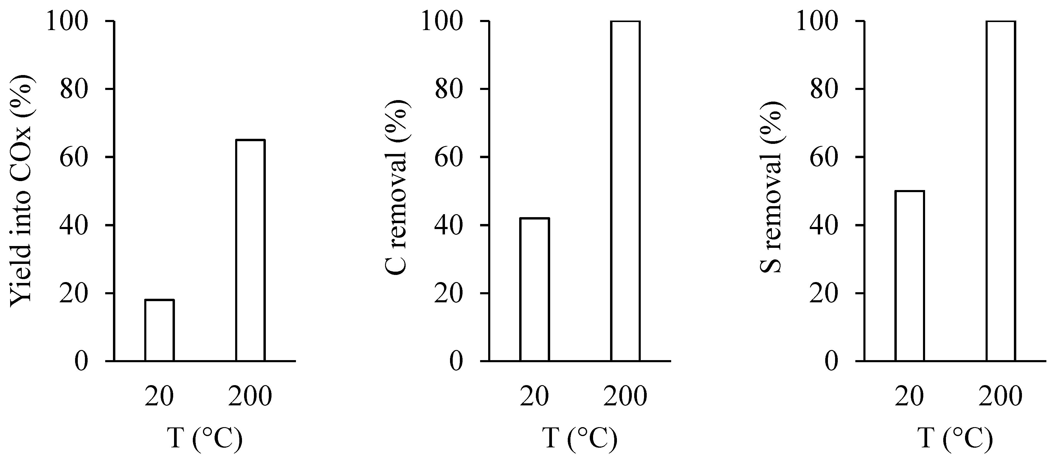
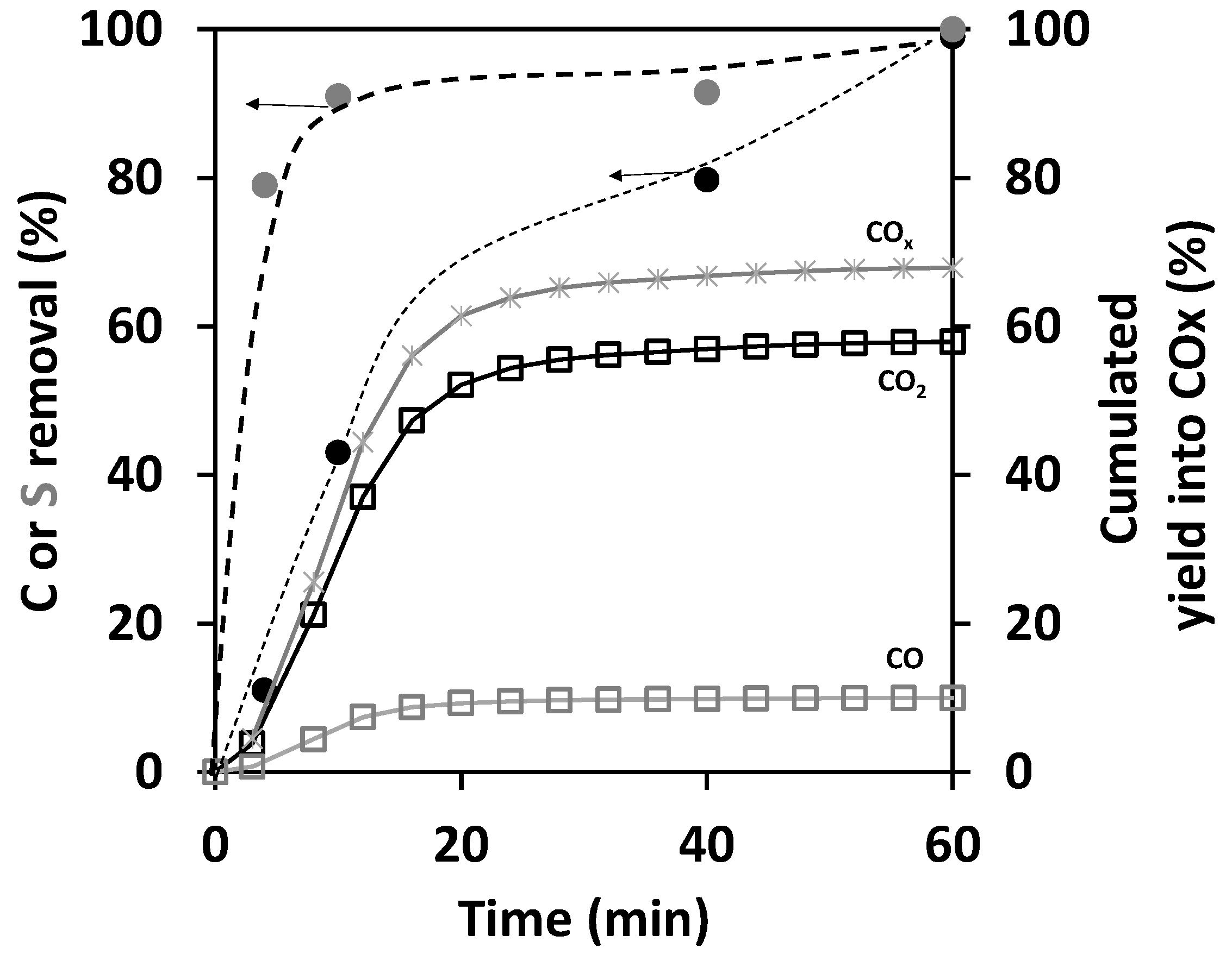
 ) and sulfur (
  ) removal on the spent catalyst with the cumulated yields of CO (
  ), CO2 (
  ), and their sum (
  ). Experiments were performed at P = 7 W and 200 °C.
) and sulfur ( ) removal on the spent catalyst with the cumulated yields of CO ( ), CO2 ( ), and their sum ( ). Experiments were performed at P = 7 W and 200 °C.
). Experiments were performed at P = 7 W and 200 °C.
) and sulfur ( ) removal on the spent catalyst with the cumulated yields of CO ( ), CO2 ( ), and their sum ( ). Experiments were performed at P = 7 W and 200 °C.


| Oxide/Element (wt.%) | P2O5 | MoO3 | CoO | C | S |
|---|---|---|---|---|---|
| Spent catalyst | 5.2 | 20.3 | 4.0 | 13.0 | 8.8 |
| Extracted coke | - | 14.0 | 0.6 | 15.1 | 4.9 |
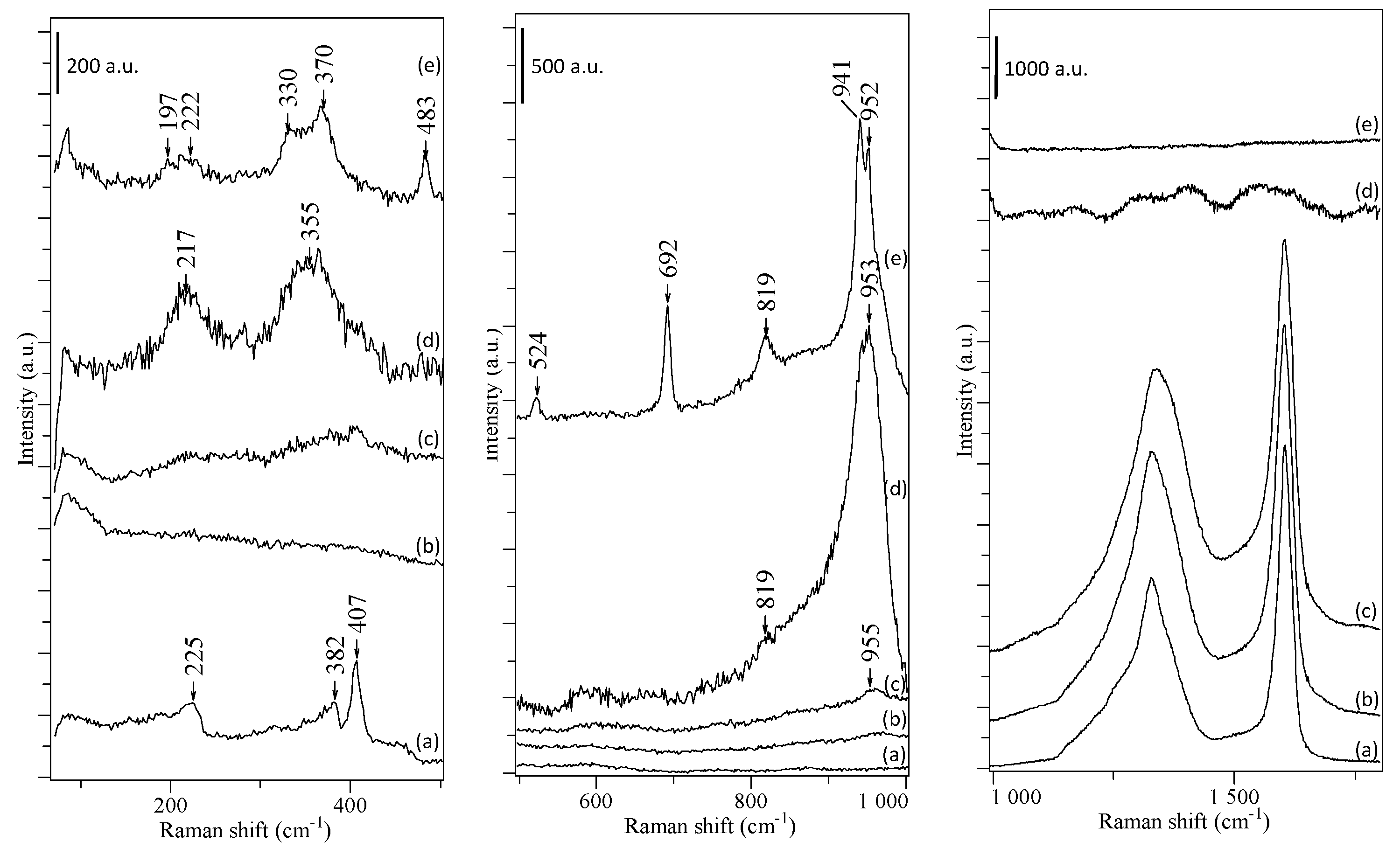
| Assignment | Peak Position (cm−1) | Ref |
|---|---|---|
| CoMoO4 | 330, 370, 819, 941, 952 | [19,32] |
| CoMo6 or AlMo6 | 217, 351, 376, 573, 909, 952 | [19] |
| Co3O4 | 197, 483, 524, 692 | [33] |
| MoS2 | 225, 382, 405 | [28] |
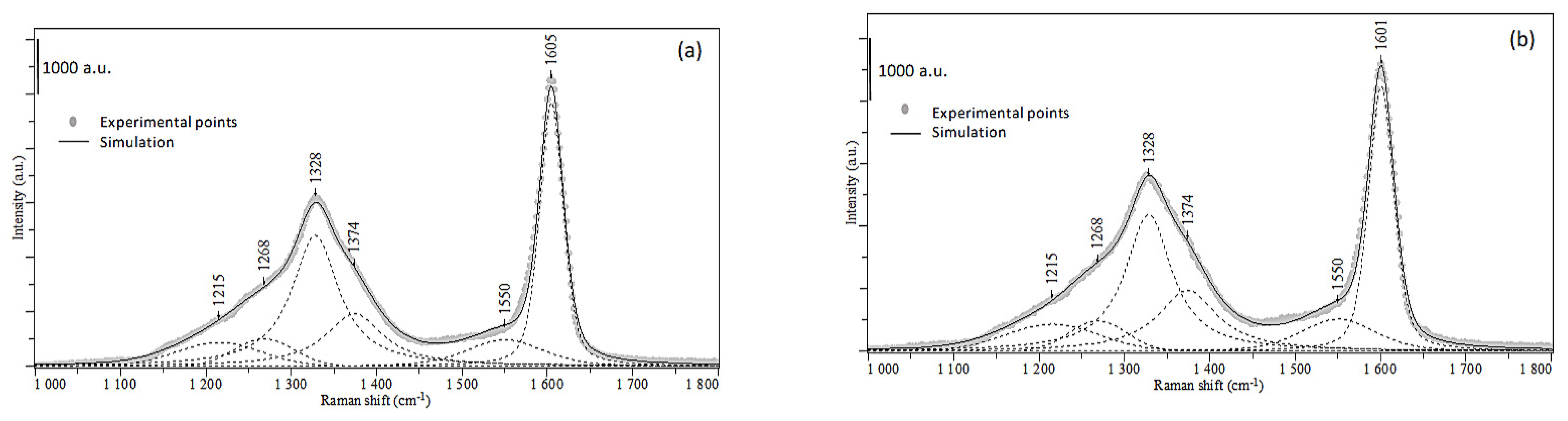
| Graphitic carbon (G peak) | 1580–1600 | [29] |
| Disordered amorphous carbon (D peak) | 1338 | [29] |
| Carbon sp3 | 1215 | [30] |
| Carbon sp2 (amorphous phase) | 1550 | [31] |
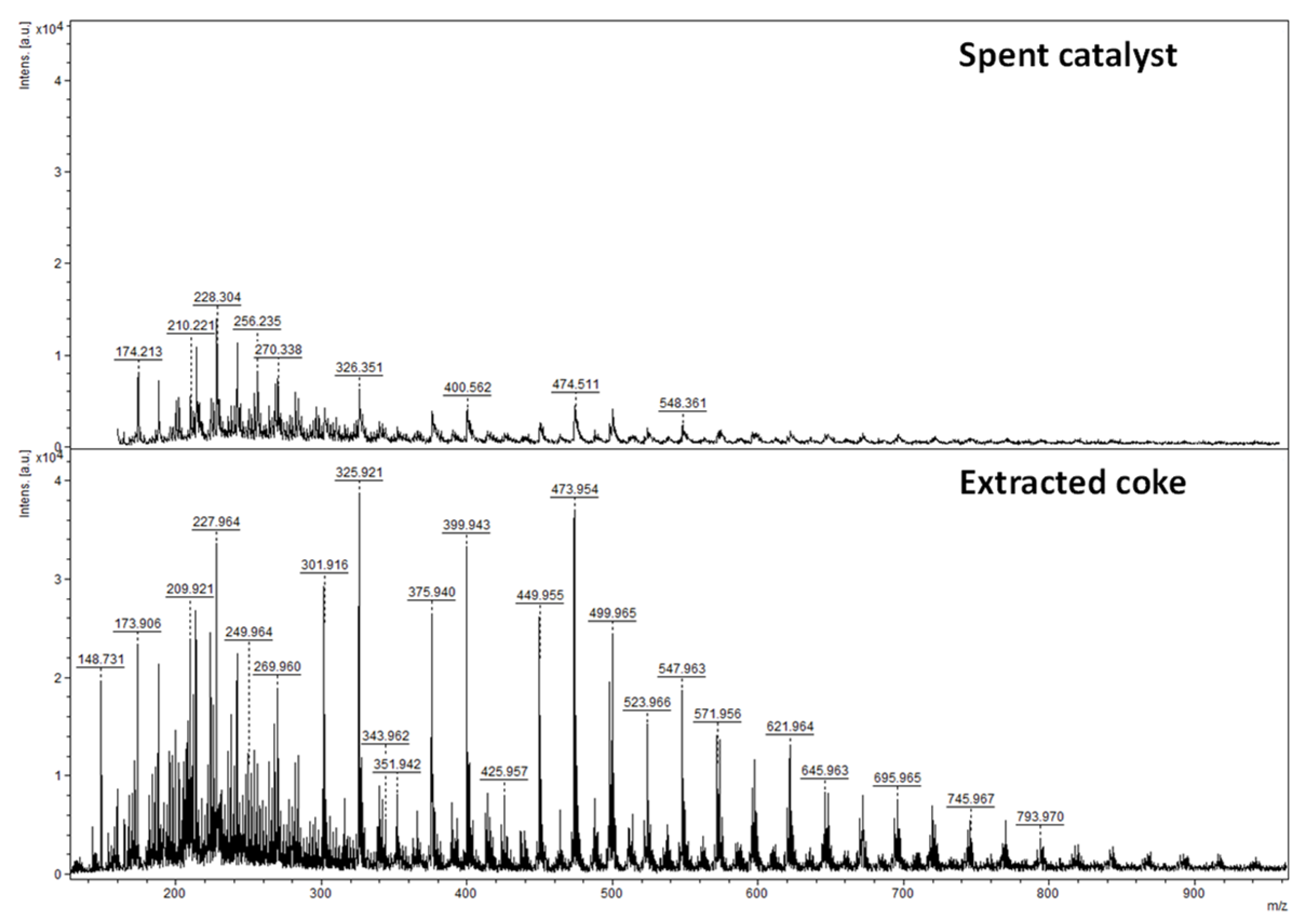
| Degree of. Ensaturation (DU) | Chemical Formula | Number of Alkyl Groups Attached to the Structural Unit | Number of SO Units Attached to the Structural Unit | Molecular Weight (m/z) |
|---|---|---|---|---|
| Spent catalyst | ||||
| 9 | C15H14O, C16H16O,C17H17O | 3, 4 5 | 210.221, 224.222, 238.251 | |
| 12 | C16H10, C17H12, C18H14, C20H22, C21H24 | 0, 1, 2, | 202.209, 216.209, 230.229 | |
| 13 | C18H12, C19H14, C20H16, C21H18, C22H20, C25H26 | 0, 1, 2, 3, 4, 7 | 228.304, 242.306, 256,235, 270.338, 284,380, 326,351 | |
| Extracted coke | ||||
| 8 | C15H12O, C16H14O, C17H16O, C18H18O, C19H20O | 3, 4, 5, 6, 7 | 208.681, 221.965, 235.937, 249.964, 263.983 | |
| 9 | C12H8O, C13H10O, C14H12O, C15H14O, C16H16O, C17H18O C18H20O | 0, 1, 2, 3, 4, 5, 6 | 167.855, 191.877, 195.897, 209.921, 223.944, 237.963, 251.982 | |
| 11 | C20H20, C21H21 | 4, 5 | 259.952, 273.966 | |
| 13 | C15H6, C16H8, C17H10, C18H12, C20H16, C21H18, C22H20, C25H26 | 0, 1, 2, 3, 5, 6, 7, 10 | 199.933, 213.954, 227.964, 241.976, 255.976, 269.960, 283.969 | |
| C23H12O2S, C23H12O3S2 C24H26O3S2 C24H26O4S3 | 0, 1 | 1, 2 | 351.942, 399.943, 425.957, 473.954 | |
| C23H16O5S4 C23H16O6S5 C23H16O7S6 | 1, 2, 3 | 499.965, 547.963, 595.959 | ||
| C23H18O6S5 C23H18O7S6 C23H18O8S7 | 1, 2, 3 | 549.975, 597.966,645.963 |
Publisher’s Note: MDPI stays neutral with regard to jurisdictional claims in published maps and institutional affiliations. |
© 2021 by the authors. Licensee MDPI, Basel, Switzerland. This article is an open access article distributed under the terms and conditions of the Creative Commons Attribution (CC BY) license (https://creativecommons.org/licenses/by/4.0/).
Share and Cite
Srour, H.; Guignard, N.; Tarighi, M.; Devers, E.; Mekki-Berrada, A.; Toufaily, J.; Hamieh, T.; Batiot-Dupeyrat, C.; Pinard, L. Regeneration of an Aged Hydrodesulfurization Catalyst by Non-Thermal Plasma: Characterization of Refractory Coke Molecules. Catalysts 2021, 11, 1153. https://doi.org/10.3390/catal11101153
Srour H, Guignard N, Tarighi M, Devers E, Mekki-Berrada A, Toufaily J, Hamieh T, Batiot-Dupeyrat C, Pinard L. Regeneration of an Aged Hydrodesulfurization Catalyst by Non-Thermal Plasma: Characterization of Refractory Coke Molecules. Catalysts. 2021; 11(10):1153. https://doi.org/10.3390/catal11101153
Chicago/Turabian StyleSrour, Hawraa, Nadia Guignard, Mehrad Tarighi, Elodie Devers, Adrien Mekki-Berrada, Joumana Toufaily, Tayssir Hamieh, Catherine Batiot-Dupeyrat, and Ludovic Pinard. 2021. "Regeneration of an Aged Hydrodesulfurization Catalyst by Non-Thermal Plasma: Characterization of Refractory Coke Molecules" Catalysts 11, no. 10: 1153. https://doi.org/10.3390/catal11101153
APA StyleSrour, H., Guignard, N., Tarighi, M., Devers, E., Mekki-Berrada, A., Toufaily, J., Hamieh, T., Batiot-Dupeyrat, C., & Pinard, L. (2021). Regeneration of an Aged Hydrodesulfurization Catalyst by Non-Thermal Plasma: Characterization of Refractory Coke Molecules. Catalysts, 11(10), 1153. https://doi.org/10.3390/catal11101153