Article

Degradation of Acid Orange 7 Azo Dye in Aqueous Solution by a Catalytic-Assisted, Non-Thermal Plasma Process

1
Department of Industrial Engineering, University of Salerno, via Giovanni Paolo II, 132, 84084 Fisciano (Salerno), Italy
2
Department of Pharmacy, University of Salerno, via Giovanni Paolo II, 132, 84084 Fisciano (Salerno), Italy
*
Author to whom correspondence should be addressed.
Catalysts 2020, 10(8), 888; https://doi.org/10.3390/catal10080888
Submission received: 15 July 2020 / Revised: 29 July 2020 / Accepted: 3 August 2020 / Published: 5 August 2020

Abstract

:
The aim of this work was the optimization of the performance of the cold plasma technology coupled with a structured catalyst for the discoloration and mineralization of “acid orange 7” (AO7) azo dye. The structured catalyst consists of Fe2O3 immobilized on glass spheres, and it was prepared by the “dip coating” method and characterized by different chemico-physical techniques. The experiments were carried out in a dielectric barrier discharge (DBD) reactor. Thanks to the presence of the catalytic packed material, the complete discoloration and mineralization of the dye was achieved with voltage equal to 12 kV, lower than those generally used with this technology (approximately 20–40 kV). The best result in terms of discoloration and mineralization (80% after only 5 min both for discoloration and mineralization) was obtained with 0.25 wt% of Fe2O3 immobilized on the glass spheres, without formation of reaction by-products, as shown by the HPLC analysis. The optimized catalyst was reused for several reuse cycles without any substantial decrease of performances. Moreover, tests with radical scavengers evidenced that the most responsible oxidizing species for the degradation of AO7 dye was O2•−.

1. Introduction

Nowadays, the presence of not so easily biodegradable pollutants in wastewater represents an extremely interesting environmental problem. The reason is the ability of these pollutants to remain in the environment or to “escape” from conventional purification processes. An example is represented by the azo dyes which are widely used in the textile industry. The dyeing step is one of the most important phases in this sector. The dye is added to the fibers but during this phase some dyes are poured into the industrial wastewater [1]. Dyes are characterized by high intensity and brilliance and are perceptible even at low concentrations [2,3]. Their presence in aquatic system is dangerous for the environment due to the fact of their not biodegradability, toxicity, and potential carcinogenic nature [4]. In an aquatic ecosystem, the dyes not only inhibit the photosynthesis activity of aquatic biota but also have direct toxic effects on them [5]. Several textile and food dyes have been linked to carcinogenicity such as dye intermediaries like benzidine [5]. Traditional methods for the dye’s removal from wastewater are often based on adsorption processes that only transfer the contaminant from the liquid phase to the solid one (non-destructive process) [6]. Furthermore, ascertaining that the dye does not transform into by-products reaction once it degrades is important: this can happen with conventional oxidation processes. In fact, many of the most common methods based on coagulation, adsorption, membrane separation or traditional oxidation present some disadvantages, such as high sludge production, expensive regeneration, chemicals required, and formation of by-products [5,7,8]. Since conventional purification processes are not suitable for the degradation of these contaminants, scientific research is concerned with studying the potential of innovative processes capable of completely mineralizing these types of organic contaminants. Advanced oxidation processes (AOPs) are ideal in the pollutants’ removal from wastewater effluent [7,9,10,11,12,13,14]. They are economic, powerful, and easy to use [15]. Cold plasma or “non-thermal plasma” technologies are part of AOPs which are, in recent years, intensively studied among the degradation of pollutants [16]. Cold plasma is characterized by a large amount of high-energy species and, in contact with liquid phase, it is able to produce different active species, such as OH·, H·, O·, HO2·, H2O2, and O3, which could degrade various organic pollutants [17]. Because of its extraordinary effectiveness, cold plasma is used in various fields regarding water and wastewater treatment, waste gas, surface treatment, sterilization process, and deactivation of microorganisms [18,19,20,21,22,23]. In order to induce cold plasma, there are different types of reactors such as corona discharge [24], dielectric barrier discharge (DBD) [19], plasma jet [25] or gliding arc [17]. Among these reactors, dielectric barrier discharge (DBD) presents, as advantages, a high removal rate for contaminants and a simple functioning, receiving more attention among the water treatment field in recent years [26]. However, some studies showed that sometimes the only use of non-thermal plasma (NTP) generated by the DBD does not guarantee the complete degradation of organic contaminants. Furthermore, without a catalytic material, it may be necessary to adopt operating conditions, requiring the use of very high voltages to induce cold plasma [27]. For this reason, the synergistic effect of NTP with catalysts is certainly an interesting topic [28]. Plasma catalysis synergy is a complex phenomenon that implies the interaction process between plasma and catalyst [29,30,31]. The introduction of catalyst into the plasma discharge region may influence the discharge type and cause a change in electron distribution which acts on the generation of short-lived reactive plasma species [29]. The use of different kinds of catalysts in a DBD reactor is reported in literature. Among the various photocatalytic materials used, certainly the classic TiO2 and ZnO are widely used too. For example, Pekárek et al. [32,33] investigated the ozone generation efficiency by using ZnO or TiO2 coupled with DBD for the NTP process. They showed that, although ZnO acts as photocatalysts just like TiO2, it was subject to the phenomenon of photocorrosion, which led to the reduction of photocatalytic activity.
A possible solution was proposed by Zhang et al. [34] who reported the use of titanium dioxide–graphene oxide nanomaterials (TiO2–GO) as catalytic material combined to DBD (discharge power = 20 W) for the degradation of acetaminophen. The results showed that the degradation of this pollutant, by using NTP combined with TiO2–GO catalyst, was more efficient than the single NTP. Degradation of phenol (100 mg/L) in water was examined in a non-thermal plasma (18 kV) reactor combined with CeO2, Fe2O3/CeO2, and ZrO2/CeO2 catalysts, and the results were reported by Reddy et al. [35], highlighting that the catalyst addition to NTP improves the phenol degradation. In particular, in the presence of ZrO2/CeO2 catalyst, the phenol degradation was equal to 91% after 25 min, against 60% with plasma alone. This is due to the addition of a catalyst in the reactor that enhances the life time of short-lived oxidized species formed with NTP and/or facilitates the formation of secondary oxidants like atomic oxygen by the ozone decomposition [35]. Wang et al. [36] proposed a plasma technology combined with 2.5 g/L of goethite (mineral consisting of iron hydroxide) for the removal of caffeine (50 mg/L) from aqueous solutions. The input power was 75 W. In order to treat the goethite, it was placed into a quartz reaction (between the two electrodes) and suspended in the solution. The DBD–goethite system showed a very interesting performance: a 24 min treatment removed 94% of the pollutant against the 41% obtained with only plasma. Jovića et al. [37] compared the performance of a DBD reactor with a DBD in the presence of homogeneous catalysts for the degradation of an herbicide. The reactor operated at atmospheric pressure, with an air flow rate of 5 NL/min and a voltage equal to17 kV. The catalysts considered in this study were Mn2+, Co2+, and Fe2+. The most efficient DBD system was the one combined with Fe2+ which removed 50% more contaminant than the DBD reactor alone. However, the homogeneous character of these catalysts should be underlined, besides potential complications in their management, during the treatment and final disposal of the wastewater, due to the possible formation of sludge caused by the precipitation of the metals used or due to the presence of a residue in high concentrations. More specifically, as regards the degradation of the dyes in aqueous solution, in the literature, there are some studies that report the use of catalyst in an NTP reactor [38,39,40]. Fahmy et al. [38] reported the results of the use of a corona discharge NTP reactor, operating with a voltage of 12.5 kV and coupled with a catalyst based on Fe2+ (homogenous phase) for the degradation of acid orange 142 (20 mg/L) in aqueous solution. Optimal results were obtained using a specific catalyst dosage (0.9 mM of Fe2+): after 20 min of treatment, in the presence of Fe2+ catalyst, the discoloration was equal to 95%. Liu et al. [39] proposed a GAD (gliding arc discharge) plasma reactor (10 kV) combined with a TiO2-based catalyst immobilized on γ-Al2O3 in order to use the ultraviolet light from the discharge and activate the photocatalyst. In this way, more active oxygen species can be generated in the plasma, such as hydroxyl radicals able to improve the degradation of AO7; in particular, in 40 min 43.6% of contaminant was degraded. Reddy et al. [40] analyzed the degradation and mineralization efficiency of methylene blue (100 mg/L) in a DBD reactor operating at 16 kV in the presence of Fe2+ catalyst (60 mg/L). The addition of the Fe2+ promoted the degradation of the dye (97% after 24 min of treatment) through Fenton-type reactions (reaction between Fe2+ and H2O2 produced during the plasma process). Generally, the catalyst used in the DBD reactor was in the homogeneous phase or in powder form (heterogeneous phase) and not supported on a macroscopic material. In particular, when the heterogeneous catalyst was used, it was placed in the discharge zone [36]. This was probably because, in order to improve the formation of the radical species, the catalytic active species were in direct contact with the discharge. Heterogeneous catalyst can be combined with NTP in two ways: by introducing the catalyst in the discharge zone or by placing the catalyst after the discharge zone [41]. In both configurations, heterogeneous catalyst material can be introduced in the reactor through a different form, in particular, as coating on the reactor or electrodes wall, as a packed-bed (using structuring catalyst in different forms such as granulates, coated fibers or pellets), or as a layer of structured catalytic material (e.g., powder, pellets, granulates, coated fiber) [41]. The use of catalytic packed materials, suitably inserted in the DBD reactor, can improve the distribution of discharges and, therefore, the production of active species. Considering the potentiality of specific catalysts, such as Fe-based catalyst, the aim of this work was to improve the performance of the DBD reactor, using glass spheres as support for Fe2O3. The efficiency and potential of this DBD catalytic system were tested for the degradation of an azo dye typically used in the textile industry, acid orange 7 (AO7). In particular, the novelty concerned the possibility of completely removing the dye without the formation of intermediates, applying low voltages (about 12 kV) compared to those generally used in this system and in very short times.
In this work, a study was also conducted to define the main oxidizing species responsible for the AO7 dye degradation mechanism, with and without catalyst in the DBD reactor. In this way, it was possible to identify that the oxidizing species are able to promote the catalytic effect. Moreover, a specific analysis was performed in order to exclude the presence of possible by-products.

2. Results

2.1. Characterization Results

2.1.1. Specific Surface Area (SSA)

Specific Surface Area (SSA) values of the structured catalysts used in the DBD reactor are reported in Table 1. It is possible to observe that the SSA of the glass spheres coated with a specific amount of catalyst increased with respect to raw glass spheres (SF). This is due to the Fe2O3 coating resulted on a surface with a higher porosity than the raw glass spheres one as observed from SEM analysis (Figure 1).

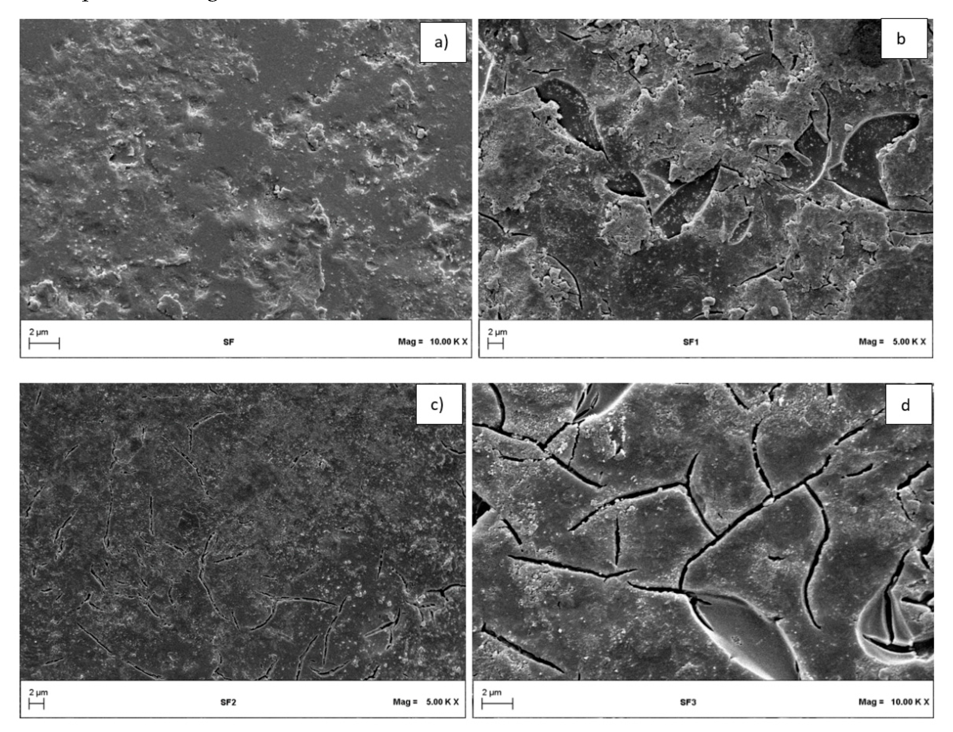
2.1.2. SEM Images Results

The surface morphology of SF samples was investigated by SEM microscopy and the obtained results are reported in Figure 1.
The SEM images of the raw glass sphere’s (SF) surface shows only the presence of some surface cracking due to the roughness of the glass induced by the thermal pre-treatment of the support (Figure 1a). After the first dip-coating step (SF1), the presence of almost homogeneous Fe2O3 film was observed. However, it should be noted, that for these samples (SF1), some visible cracks and a small fraction of glass surface not covered by Fe2O3 particles are present (Figure 1b).
The second dip-coating step (SF2) induced the presence of a homogeneous Fe2O3 layer on glass substrate (Figure 1c). The third dip-coating step (SF3) provides the formation of a thick catalytic layer characterized by clear macro-fractures (Figure 1d).

2.1.3. Raman Analysis

The Raman spectra of the raw glass spheres (SF), in comparison with the SF1, SF2, and SF3 samples, and with Fe2O3 in powder form recovered after the calcination step are shown in Figure 2. In the range 150–400 cm−1, for the Fe2O3 sample in powder form, it is possible to note the characteristic bands of Fe2O3 at 226 and 293 cm−1 [42], confirming that the used calcination conditions were able to induce the formation of Fe2O3.
A wide band characteristic of the support material (glass) at approximately a 347 cm−1 Raman shift was observed. The intensity of this band diminished the increase of the number of dip-coating steps (in particular for SF2 and SF3 samples) and, consequently, of the catalyst load on the glass sphere’s surface. This may indicate that the glass sphere’s surface was progressively covered by Fe2O3 film. For the SF1 and SF2 samples, there was no real difference compared to the Raman spectrum of the raw glass spheres (SF), probably because the catalyst load in these samples was still too low to be detected by Raman analysis. On the contrary, for the SF3 sample, typical bands of the Fe2O3 begin to be visible at Raman shift equal to 227 cm−1 and 294 cm−1. In particular, for these bands, a slight shift towards higher Raman shift value was observed. This could be caused by a strong interaction between Fe2O3 and the glass surface, as confirmed also by the literature [43]. These results demonstrated that the dip-coating method was able to induce the formation of Fe2O3 deposited on the surface of glass spheres.

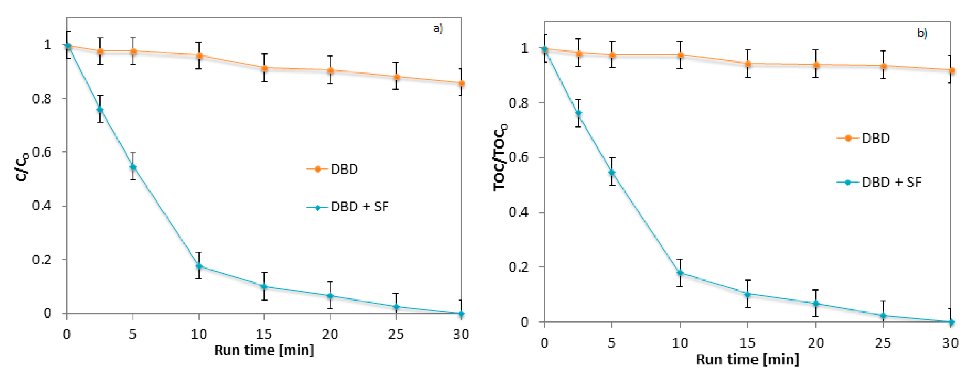
2.2. Influence of Packed Material on DBD Performances

As reported in the literature [44], the presence of a packed material can improve the performance of a cold plasma DBD reactor. For this purpose, experimental tests were conducted both with and without glass spheres. In particular, the experiments were carried out by applying a voltage equal to 12 kV. Results in terms of discoloration (C/C0) and mineralization (TOC/TOC0) are reported in Figure 3a,b, respectively.
The effect of the presence of glass spheres was remarkable, since the performances of the process were increased, applying a low voltage equal to about 12 kV too. In fact, in the absence of the glass spheres, it was possible to note that, at the same applied voltage, the system did not guarantee the formation of a sufficient number of oxidizing species, resulting, as a consequence, in a low discoloration and mineralization efficiency (14% of discoloration and 8% of mineralization after 30 min). This result is consistent with literature data: the performance of the DBD plasma reactor improves by inserting a packing material in the reactor, because the high dielectric constant of the packing material allows the generation of a greater number of micro-discharges, creating a strong electric field at the edges and corners of packed material [44]. In the literature, the effect of different packed materials on the efficiency of cold plasma is reported. In particular, as regards the CO2 conversion, it was demonstrated that the presence of the packing materials in the discharge zone can increase the average intensity of the generated electric field [45]. It was observed that the nature of the packed material represents a key parameter for the performances of the DBD plasma. Among the most used materials for this purpose there are quartz, alumina or silica glasses due to the fact of their high dielectric constant [46]. Moreover, the introduction of a dielectric material as spheres or pellets into the plasma reactor leads to an increase of the electric field which increases the electron energy [46]. Generally, it is possible to confirm that the improved effect of packing material may be due to the surface activation. In the literature, few works about the use of glass spheres or other filling materials for the treatment of aqueous solutions with cold plasma are reported. Interesting results, regarding the use of glass spheres to increase the performance of the DBD reactor have been reported for the CO2 decomposition [44]. In this case, the authors tested the performance of different materials (i.e., TiO2, glass spheres, Al2O3, and CeO2). For the CO2 decomposition, they obtained the best results in the presence of TiO2 pellets [44]. As regards the treatment of contaminated water, Wu et al. [47] report the use of a cold plasma reactor combined with a glass bead-packed bed for methylene blue degradation. In their coupled system, the degradation efficiency of 100 ppm MB solution reached 97.9% with 10 min of treatment.

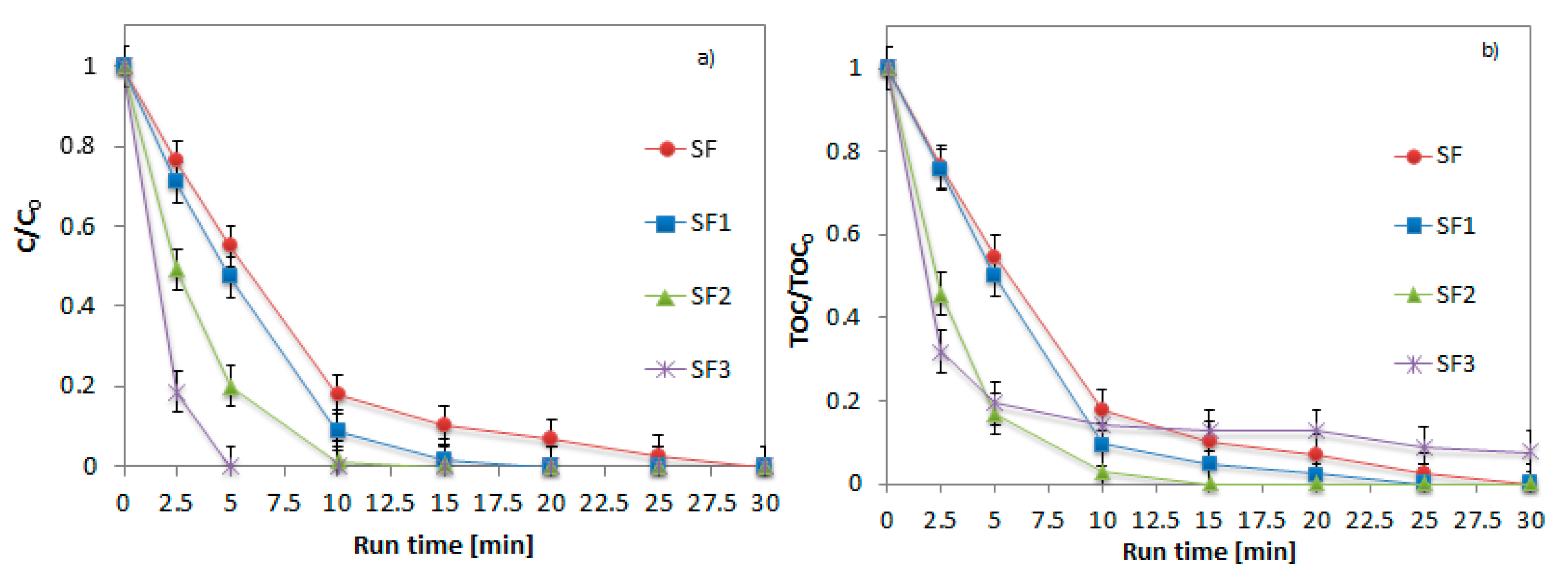
2.3. Effect of Fe2O3 Amount on Glass Spheres Surface

The effect of the Fe2O3 amount immobilized on glass spheres (in the range 0.13–0.37 wt%) in terms of AO7 (20 mg/L) discoloration (a) and mineralization (b) is shown in Figure 4.
During the tests, it was possible to note a progressive decrease of AO7 concentration, obtaining a discoloration equal to 53%, 80%, and 100% with the SF1, SF2, and SF3 samples (Figure 4a), respectively, after only 5 min of reaction time; after the same treatment time, the mineralization was equal to 53%, 80%, and 78% for the identical samples (Figure 4b).
This effect is due to the presence of iron oxide (Fe2O3) which acts as a photocatalyst, activated by the presence of UV light emitted by the ionized gas [4,36,48]. In particular, the best performances in terms of discoloration and simultaneous mineralization of AO7 dye were obtained with the SF2 catalyst. In fact, with this sample, the simultaneous discoloration and mineralization was achieved after 5 min of treatment time. With the SF2 sample the total discoloration and mineralization of AO7 was obtained after only 10 min of reaction time. However, with the increase of the Fe2O3 amount of glass sphere surface (SF3 sample), the catalytic performances decreased. In particular, the SF3 sample showed good results in terms of discoloration (100% after only 5 min) but not in terms of mineralization (equal to 78% after the same treatment time). In fact, observing the total organic carbon (TOC) behavior, it is possible to note that in the case of the SF3 catalyst, there was no simultaneous discoloration and mineralization. This result indicates that, probably, with the SF3 sample, the formation of reaction intermediates is possible and they do not guarantee the complete mineralization of the pollutant. Considering these results, it is possible to argue that the optimal Fe2O3 amount on glass spheres was equal to 0.25 wt%. In fact, the performances of SF2 catalyst are better than SF3 due to the better distribution of the Fe2O3 on the glass sphere (as observed from SEM images) after two dip-coating steps. In order to confirm the absence of reaction by-products, HPLC analyses were conducted and the results are reported in Figure 5.
As it is possible to observe from the mass spectra (Figure 5a) and chromatographic profile (Figure 5b), AO7 was completely removed after only 10 min of reaction time, because no by-product formation was observed during the first few minutes of reaction.

2.4. Recyclability Tests of SF2 Catalyst in DBD Reactor

The recyclability tests are a very important parameter to be investigated for a structured catalyst formulation [49,50]. With the aim of evaluating the stability of the SF2 sample, recycle tests were performed for twenty cycles in presence of the same experimental conditions (Figure 6).
The results demonstrated that the catalytic performances did not change both in terms of discoloration (Figure 6a) and in terms of mineralization (Figure 6b), suggesting the absence of the corrosion phenomena of Fe2O3 catalyst and demonstrating its stability after several reuse cycles. This result evidences the possibility to use the SF2 sample as structured catalyst to be used in the cold plasma process for water treatment.

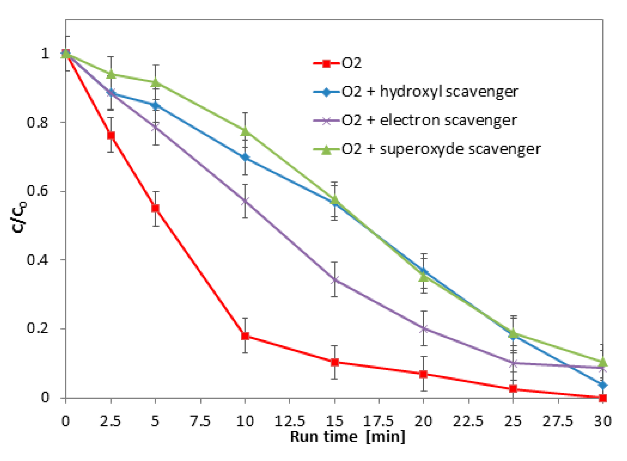
2.5. Role of the Main Oxidizing Species

As reported also in literature, the cold plasma efficiency was mainly due to the formation of chemically active species, including “short-lived” active species (such as OH, NO, O, O2, HO2, and H) and “long-lived” active molecules (such as H2O2, O3, and other excited-state neutral molecules) [39]. In this section, the results about the identification of the main oxidizing species (responsible for the degradation of AO7 during the cold plasma application in presence of SF2 catalyst) are reported. The first effect taken into consideration concerned ozone: the O3 concentration in the DBD reactor was due to the presence of oxygen used as process gas during the tests. For this purpose, an experiment in the presence of He was performed (O2 concentration equal to zero), and the results were compared with those obtained in the presence of O2 (Figure 7).
It was possible to note that, in the absence of oxygen (and, therefore, in the absence of generated O3), after 10 min of treatment, the discoloration and mineralization were equal to only 33%, against 100% obtained in the presence of oxygen. This result confirms the importance of O3 in the degradation of the target dye, as validated by literature data. In particular, Du et al. [4] evaluated the discoloration efficiency of AO7 in presence of different process gas (with different O2 concentration) like oxygen, air, argon, and nitrogen, showing that the discoloration obtained after 25 min of plasma treatment was equal to 86.7%, 58.9%, 55%, and 50% in presence of oxygen, argon, air, and nitrogen, respectively. The highest concentration of O3, which is obtained by feeding oxygen to the reactor, is responsible for the maximum rate of discoloration and mineralization of the AO7.
In addition to the O3 effect, the role of other oxidizing species in the AO7 degradation was evaluated. In particular, specifying the main reactions that take place in our system, it is important to develop this study. Furthermore, the distinction among the reactions that cause the production of oxidizing species is necessary: if they are due to the cold plasma or to the presence of the catalyst [39]. As reported in the literature, the reactions responsible for the formation of oxidizing species, such as OH, H, e, HO2, H2O2 and O3, due to the cold plasma, can be reported as follows:
H2O + eOH +H + e
O2 + e → 2O + e
O2 + H → HO2
HO2 + HO2 →H2O2 + O2
OH + OH → H2O2
O2 +O → O3
In the presence of a catalyst in the discharge zone, the reactions for the oxidizing species production are also represented as below:
Catalyst + hν→ e +h+
e + O2 → O2•−
HO2 → O2•− + H+
OH +O3 → HO2 + O2
H2O2 + O2•−OH +OH + O2
In order to evaluate the role of oxidizing species, such as OH, O2•−, and e, tests in the presence of radical scavengers were carried out. Specifically, in the presence of SF2 catalyst, with an oxygen flow rate equal to 0.18 NL/min, and an initial AO7 concentration equal to 20 mg/L, isopropyl alcohol (100 mM), benzoquinone (100 mM) and potassium dichromate (100 mM) were added in 100 mL of AO7 water solution as OH, O2•− and e scavengers, respectively. The results in terms of AO7 discoloration are reported in Figure 8.
The results show that, in this system, the main oxidizing species responsible for the AO7 discoloration is represented by the O2•− radical. Specifically, it is possible to note that, in the presence of isopropyl alcohol (OH scavengers), 15 min are required for the complete discoloration versus 10 min without OH scavengers. In the presence of e scavengers, the discoloration of the AO7 is equal to 57% after 30 min of treatment. In presence O2•− scavenger, the discoloration was almost totally inhibited. Equations (1)–(11) can be useful to understand these results. As observed in Figure 9, the O2•− plays a key role in the catalytic-assisted cold plasma process of discoloration of AO7. This oxidizing species can be formed either by the reaction of O2 with electrons (8) or by the deprotonation of the hydroperoxyl radical (9). The hydroperoxyl radical derives from the reaction between oxygen and •H (3) or from the reaction between ozone and •OH (10).
If •OH scavengers are added to the aqueous solution of AO7, the discoloration occurs slowly because the reaction (10), which leads to the formation of the HO2•, (from which the superoxides are formed) is inhibited.
On the other hand, if an electron scavenger is added to the AO7 aqueous solution, the superoxide formation is inhibited for different reasons. In particular, the reaction of O2 with electrons (8) and the dissociation reaction induced by electrons (1) are inhibited. As a consequence, reactions (3) and (10) responsible for the formation of the hydroperoxyl radical (from which superoxides are formed) are limited.
In order to better evaluate the role of the catalyst in the formation of oxidizing species, the radical scavengers were added to the solution in presence of only the packed material (SF). The results in terms of AO7 discoloration are reported in Figure 9.
The obtained results show that, in the absence of Fe2O3 catalyst coated on glass spheres, the discoloration was equally favored by O2•− and •OH and not only by O2•− as observed in presence of SF2. These results indicate that, probably, the catalyst promotes the reaction (12) responsible for the formation of hydroperoxyl radical.

3. Materials and Methods

3.1. Structured Photocatalysts Preparation

The packed bed catalytic material was made of glass spheres coated with Fe2O3 film. In particular, the glass spheres used as support material (Microglass Heim, Naples, Italy) presented a diameter equal to 5 mm. The glass spheres were pre-treated by washing with distilled water and then calcined at 450 °C for 2 h. The immobilization of Fe2O3 film on glass spheres were carried out through the “dip-coating” technique [50]. In particular, a beaker containing the Fe2O3 precursor salt (iron acetate, 10 mg) dissolved in distilled water (60 mL) was placed on a heating plate at a temperature of 80 °C. In the obtained solution, 100 g of glass spheres were immersed in and kept under stirring for 30 min at 80 °C. At this point the spheres were separated from the solution and calcined at 450 °C for two hours. In the present work, the dip-coating and calcination processes were repeated three times in order to find the best Fe2O3 amount immobilized on the glass spheres surface. The excess of Fe2O3, which was not immobilized on the support, was removed by washing the spheres in distilled water using an ultrasonic bath (CEIA-CP104, Florence, Italy). The treatment was repeated until a stable weight was achieved. The Fe2O3 amount immobilized on glass spheres was measured using precision balance (Mettler Toledo). In particular, three different samples were prepared (SF1, SF2 and SF3), characterized by a different dip-coating number. The sample SF represents the raw glass spheres.
All prepared samples are reported in Table 1.

3.2. Characterization Techniques

All the prepared photocatalysts were characterized by a chemical–physical point of view through several techniques. In particular, Raman spectra were obtained with a Dispersive Micro Raman (Invia, Renishaw, Italy) equipped with 785 nm laser in the range 150–400 cm−1 Raman shift. scanning electron microscopy (SEM) (Assing, mod. LEO 420, Rome, Italy) was used to characterize the morphology of the different samples. The specific surface area (SSA) analysis was performed by the BET method using N2 adsorption with a Costech Sorptometer 1042 (Milan, Italy) after a pretreatment at 150 °C for 30 min in He flow (99.999%).

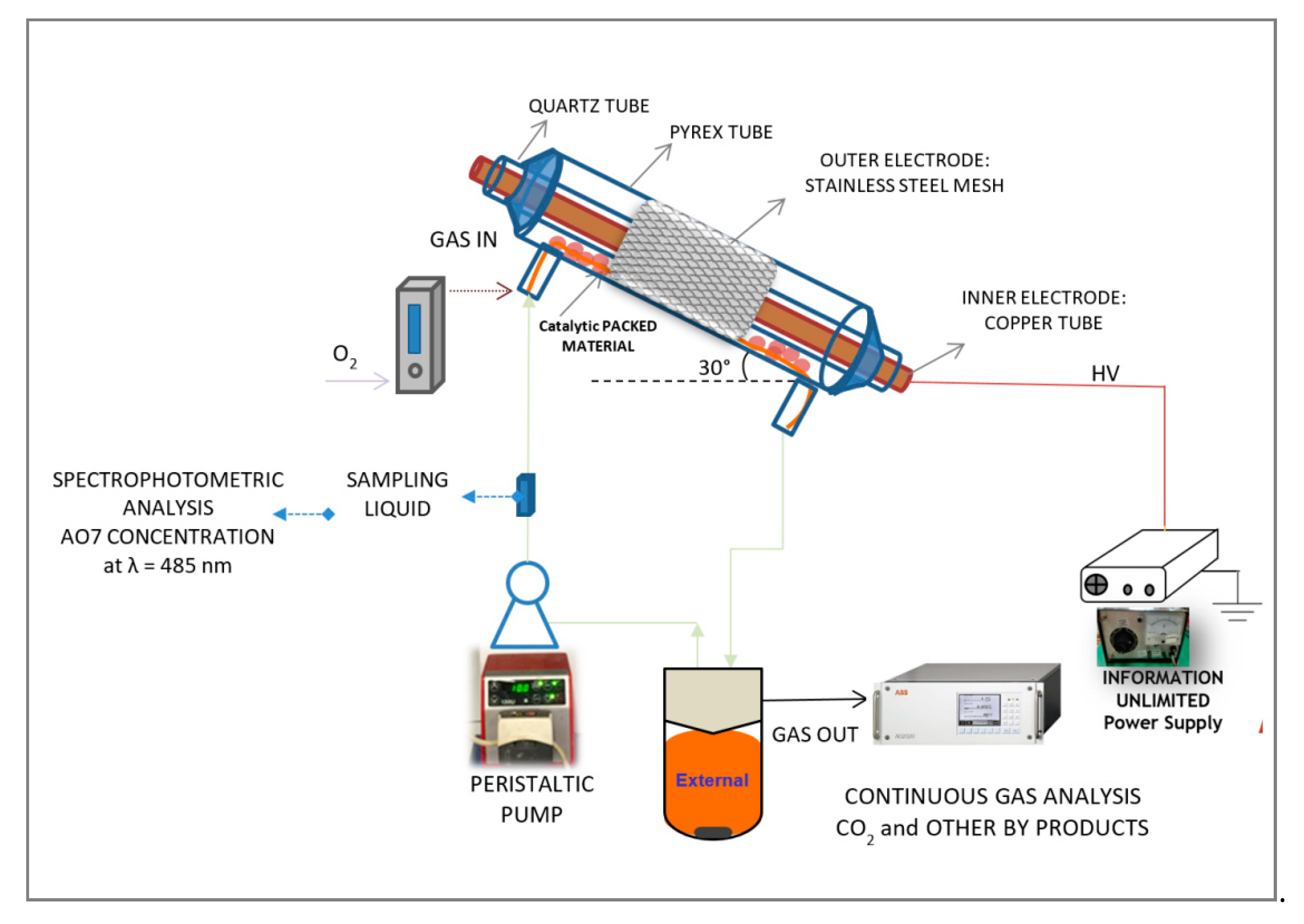
3.3. Experimental Setup and Cold Plasma Tests

The reactor configuration used to carry out the experiments was a DBD falling film reactor and was described in our previous work in detail [51]. It is a quartz cylindrical DBD reactor characterized by the presence of two electrodes: an inner electrode (a copper tube) and an outer one (stainless-steel mesh), placed at a specific distance between them. In particular, in the discharge zone inside the reactor, the catalytic packed material (glass spheres covered with Fe2O3 film) was placed, specifically using 36 g of catalytic glass spheres during the experiments. Furthermore, unlike previous work [51] and other papers reported in literature about the DBD reactors application [35], in the present study, the applied voltage between the two electrodes was lower, and it was equal to 12 kV.
The aqueous solution to be treated, with a specific initial concentration of AO7 dye, equal to 20 mg/L, was stored in an external pyrex tank. With the aid of a peristaltic pump, the solution was recirculated inside the reactor with a liquid flow rate equal to 90 mL/min. The solution flowed as a falling film on the catalyst surface on the inner side of the reactor. All experiments were performed at atmospheric pressure in presence of oxygen with flow rate equal to 0.18 NL/min. The total duration of the experiments was 1 h and 30 min in the absence of plasma (defined as the “dark” phase) to evaluate the adsorption of the contaminant on the catalyst surface, and 30 min in the presence of cold plasma generated at 12 kV.
During the tests, the liquid phase and the gas phase were analyzed as described in the following section.
The schematic representation of the reactor and the connected analysis system is shown in Figure 10.

3.4. Analytical Measurements

In order to analyze the AO7 degradation, during the experiments different liquid samples were taken from the reactor at different times. The sample were analyzed with a Thermo Fisher Evolution 201 UV–vis spectrophotometer (Italy). In particular, the AO7 concentration was determined according to the Beer–Lambert law at the maximum absorbance λ = 485 nm]. As regards the AO7 mineralization, the total organic carbon (TOC) was measured by the high temperature combustion method on a catalyst (Pt–Al2O3), in a tubular flow micro reactor operated at 680 °C, with a stream of hydrocarbon free air to oxidize the organic carbon [9].
The degradation and mineralization efficiency were evaluated according to the following equations:
Degradation   efficiency   (%) = ( 1 C C 0 ) × 100
Mineralization   efficiency   (%) = ( 1 TOC TOC 0 ) × 100
where: C = dye concentration at the generic treatment time (mg/L);
C0 = initial dye concentration (mg/L);
TOC = total organic carbon at the generic treatment time (mg/L);
TOC0 = initial total organic carbon (mg/L).
In addition, liquid chromatography analysis was performed to evaluate the presence of by-products. The LC-MS/MS analyses were performed on a Nexera UHPLC system (Shimadzu, Kyoto, Japan), consisting of a CBM-20 controller, two LC-30AD dual-plunger parallel-flow pumps, a DGU-20 AR5 degasser, a SIL-30 AC autosampler, a CTO-20AC column oven, and an SPD-M20A photo diode array detector equipped with a 2.5 μL detector flow cell volume. The UHPLC system was coupled online with an IT-TOF (ion trap-time of flight) hybrid mass spectrometer equipped with an electrospray source (ESI) (Shimadzu, Kyoto, Japan). In details, the chromatographic analysis was performed with a Kinetex® EVO C18 column (150 × 2.1 mm × 2.6 μm × 100 Å; Phenomenex, Bologna, Italy). The flow rate of the mobile phases was 0.5 mL min−1, and the oven temperature was set at 40 °C. The injection volume was 5 µL. The optimal mobile phase consisted of H2O (A) and acetonitrile (ACN) (B), both acidified at 0.1% of formic acid (v/v %). Analysis was performed in gradient elution as follows: 0.01–20.00 min, 5–95% B; 20–25.00 min, 95–95% B; and finally, 6 min for column re-equilibration. Data acquisition was set in the range 190–800 nm and chromatograms were monitored at 485 nm at the maximum absorbance of the compounds of interest. MS experiments were performed as follows: flow rate from the LC was splitt 50:50 prior to the ESI source by means of a stainless-steel Tee union (1/16 in, 0.15 mm bore, Valco, Houston, TX, USA). Resolution, sensitivity and mass number calibration of the Ion Trap and the TOF analyzers were tuned using a standard sample solution of sodium trifluoroacetate. MS detection was operated in the negative ionization mode with the following parameters: detector voltage, 1.65 kV; CDL (curve desolvation line) temperature, 250 °C; block heater temperature, 250 °C; nebulizing gas flow (N2), 1.5 L/min; drying gas pressure, 95 kPa.
Full scan MS data were acquired in the range of 100–1000 m/z (ion accumulation time, 25 ms; IT, repeat = 3). The MS/MS experiments were conducted in data dependent acquisition, precursor ions were acquired in the range 100–1000 m/z; peak width, 3 Da; ion accumulation time, 50 ms; CID energy, 50%; collision gas, 50%; repeat = 3; execution trigger (BPC) intensity, at 95% stop level. The identification of compounds was carried out on the basis of diode array detection spectra, MS molecular ions, and MS/MS fragmentation patterns. The calibration curve was obtained in a concentration range of 0.625–80 µg L−1 with eight concentration levels and triplicate injections of each level were run. Peak areas of AO7 were plotted against corresponding concentrations. Linear regression was used to generate calibration curve (y = 0.00025x + 0.22675) with R2 values was ≥ 0.9999 (LOD = 0.37 µg L−1, LOQ = 1.12 µg L−1). The LC-MS/MS data were elaborated by the LCMSsolution® software (Version 3.50.346, Shimadzu).

4. Conclusions

The efficiency of the catalytic-assisted cold plasma process, in the removal of AO7 azo dye pollutant in aqueous solution, was demonstrated in this work. The results showed that, in the presence of glass spheres as packing material in the discharge area of the DBD reactor, it was possible to obtain excellent performance in terms of AO7 discoloration and mineralization applying low voltage values (12 kV) and in very short times (10–15 min of reaction). Furthermore, through the dip coating method, it is possible to immobilize Fe2O3 on the glass spheres surface and use it as catalyst in the cold plasma process. The optimal Fe2O3 loading was equal to 0.25 wt%. In fact, this Fe2O3 amount guarantees a uniform dispersion of the Fe2O3 catalyst on the glass sphere’s surface as confirmed by the SEM analysis. Raman characterization confirmed the presence of the Fe2O3 species with a shift to the right of the main peaks of Fe2O3, demonstrating a strong interaction between the glassy support and the active species. The catalytic packed material (named SF2) improved the performance of the DBD reactor, reducing the time required for discoloration and mineralization. In particular, in presence of this catalyst, it was possible to observe a simultaneous discoloration and mineralization behavior, confirming the absence of reaction by-products. The complete degradation of AO7 was also confirmed by UHPLC analyses which demonstrated the complete absence of reaction intermediates. From this study, it emerged that, in the presence of a Fe2O3-based structured catalyst in a DBD reactor, the main oxidizing species responsible for the degradation of AO7 was represented by O2•−. In absence of the Fe2O3 catalyst, but in presence of the only packing material (glass spheres), the AO7 degradation was promoted both by the O2•− and the hydroxyl radical OH. Therefore, in this last case, there was not a single oxidizing species most responsible for the pollutants degradation, but two (O2•− and OH). This last result is interesting because it avoids the inhibition of dye degradation by radical scavengers. In fact, if the wastewater to be treated was characterized by the presence of O2•− radical scavengers, it would be appropriate to hypothesize the use of a non-catalytic packed material, such as glass spheres, rather than the use of a catalytic material.

Author Contributions

Conceptualization G.I., V.V. and V.P.; formal analysis, G.P. and P.C.; investigation, G.I. and G.P.; data curation, V.V.; writing—original draft preparation, G.I.; writing—review and editing, V.V.; visualization, V.P.; supervision, V.P. All authors have read and agreed to the published version of the manuscript.

Funding

This research received no external funding.

Acknowledgments

The authors wish to thank Maria Grilletto for the support in the experimental tests.

Conflicts of Interest

The authors declare no conflict of interest.

References

  1. Yaseen, D.; Scholz, M. Textile dye wastewater characteristics and constituents of synthetic effluents: A critical review. Int. J. Environ. Sci. Technol. 2018, 16, 1193–1226. [Google Scholar] [CrossRef] [Green Version]
  2. Clarke, E.A.; Anliker, R.; Butler, G.C.; Förstner, U.; Funke, W.; Hyslop, C.; Kaiser, G.; Rappe, C.; Russow, J.; Tölg, G.; et al. Organic Dyes and Pigments; Springer Science and Business Media LLC: Berlin, Germany, 1980; pp. 181–215. [Google Scholar]
  3. Fu, Y.; Viraraghavan, T. Fungal decolorization of dye wastewaters: A review. Bioresour. Technol. 2001, 79, 251–262. [Google Scholar] [CrossRef]
  4. Du, C.; Shi, T.; Sun, Y.; Zhuang, X. Decolorization of Acid Orange 7 solution by gas–liquid gliding arc discharge plasma. J. Hazard. Mater. 2008, 154, 1192–1197. [Google Scholar] [CrossRef] [PubMed]
  5. Ramachandra, T.; Ahalya, N.; Kanamadi, R. Biosorption: Techniques and Mechanisms, A Report. Available online: http:/ces.iisc.ernet.in/energy; http/ces.iisc.ernet.in/biodiversity; cestvr@ us. iisc. ernet (accessed on 3 August 2020).
  6. Katheresan, V.; Kansedo, J.; Lau, S.Y. Efficiency of various recent wastewater dye removal methods: A review. J. Environ. Chem. Eng. 2018, 6, 4676–4697. [Google Scholar] [CrossRef]
  7. Vaiano, V.; Iervolino, G.; Rizzo, L.; Sannino, D. Advanced Oxidation Processes for the Removal of Food Dyes in Wastewater. Curr. Org. Chem. 2017, 21, 1068–1073. [Google Scholar] [CrossRef]
  8. Vaiano, V.; Iervolino, G.; Sannino, D. Photocatalytic removal of tartrazine dye from aqueous samples on LaFeO3/ZnO photocatalysts. Chem. Eng. Trans. 2016, 52, 847–852. [Google Scholar]
  9. Vaiano, V.; Iervolino, G.; Sannino, D.; Rizzo, L.; Sarno, G.; Ciambelli, P.; Isupova, L.A. Food Azo-Dyes Removal from Water by Heterogeneous Photo-Fenton with LaFeO3 Supported on Honeycomb Corundum Monoliths. J. Environ. Eng. 2015, 141, 04015038. [Google Scholar] [CrossRef]
  10. Zammit, I.; Vaiano, V.; Iervolino, G.; Rizzo, L. Inactivation of an urban wastewater indigenous Escherichia coli strain by cerium doped zinc oxide photocatalysis. RSC Adv. 2018, 8, 26124–26132. [Google Scholar] [CrossRef] [Green Version]
  11. Arzate, S.; Pfister, S.; Oberschelp, C.; Sánchez-Pérez, J. Environmental impacts of an advanced oxidation process as tertiary treatment in a wastewater treatment plant. Sci. Total. Environ. 2019, 694, 133572. [Google Scholar] [CrossRef]
  12. Mandal, T.; Maity, S.; Dasgupta, D.; Datta, S. Advanced oxidation process and biotreatment: Their roles in combined industrial wastewater treatment. Desalination 2010, 250, 87–94. [Google Scholar] [CrossRef]
  13. Suhaimy, S.H.M.; Hamid, S.B.A.; Lai, C.W.; Hasan, R.; Johan, M.R. TiO2 Nanotubes Supported Cu Nanoparticles for Improving Photocatalytic Degradation of Simazine under UV Illumination. Catalysts 2016, 6, 167. [Google Scholar] [CrossRef] [Green Version]
  14. Zuorro, A.; Lavecchia, R.; Monaco, M.M.; Iervolino, G.; Vaiano, V. Photocatalytic Degradation of Azo Dye Reactive Violet 5 on Fe-Doped Titania Catalysts under Visible Light Irradiation. Catalysts 2019, 9, 645. [Google Scholar] [CrossRef] [Green Version]
  15. Khurana, P.; Thatai, S.; Kumar, D. Chapter 6—Destruction of recalcitrant nanomaterials contaminants in industrial wastewater. In Emerging and Nanomaterial Contaminants in Wastewater; Mishra, A.K., Anawar, H.M.D., Drouiche, N., Eds.; Elsevier: Amsterdam, The Netherlands, 2019; pp. 137–158. [Google Scholar]
  16. Liao, X.; Liu, N.; Chen, S.; Ye, X.; Ding, T. Degradation of antibiotic resistance contaminants in wastewater by atmospheric cold plasma: Kinetics and mechanisms. Environ. Technol. 2019, 1–14. [Google Scholar] [CrossRef] [PubMed]
  17. Liu, Y.-N.; Xu, H.; Zhu, S.-F.; Zhou, M.; Miao, J. Enhanced Degradation of Acid Orange 7 Solution by Non-thermal Plasma Discharge with TiO2. Plasma Chem. Plasma Process. 2014, 34, 1403–1413. [Google Scholar] [CrossRef]
  18. Schiavon, M.; Schiorlin, M.; Torretta, V.; Brandenburg, R.; Ragazzi, M. Non-thermal plasma assisting the biofiltration of volatile organic compounds. J. Clean. Prod. 2017, 148, 498–508. [Google Scholar] [CrossRef]
  19. Iervolino, G.; Sacco, O.; Vaiano, V.; Palma, V. Non-thermal plasma technology for the effective regeneration of macroscopic adsorbent materials used in the removal of patent blue V dye from aqueous solutions. Chem. Eng. Trans. 2019, 73, 151–156. [Google Scholar]
  20. Iervolino, G.; Vaiano, V.; Palma, V. Enhanced azo dye removal in aqueous solution by H2O2 assisted non-thermal plasma technology. Environ. Technol. Innov. 2020, 19, 100969. [Google Scholar] [CrossRef]
  21. Zhou, L.; Ma, C.; Horlyck, J.; Liu, R.; Yun, J. Development of Pharmaceutical VOCs Elimination by Catalytic Processes in China. Catalysts 2020, 10, 668. [Google Scholar] [CrossRef]
  22. Guo, X.; Ha, K.H.; Du, D. New Experiment of Diesel Exhaust Treatment by Atmospheric Pressure Plasma–Wood Fiber Combination. Catalysts 2020, 10, 577. [Google Scholar] [CrossRef]
  23. Nguyen, V.T.; Nguyen, D.B.; Heo, I.; Mok, Y.S. Plasma-Assisted Selective Catalytic Reduction for Low-Temperature Removal of NOx and Soot Simulant. Catalysts 2019, 9, 853. [Google Scholar] [CrossRef] [Green Version]
  24. Ajo, P.; Kornev, I.; Preis, S. Pulsed Corona Discharge in Water Treatment: The Effect of Hydrodynamic Conditions on Oxidation Energy Efficiency. Ind. Eng. Chem. Res. 2015, 54, 7452–7458. [Google Scholar] [CrossRef]
  25. Rezaei, F.; Vanraes, P.; Nikiforov, A.; Morent, R.; De Geyter, N. Applications of Plasma-Liquid Systems: A Review. Materials 2019, 12, 2751. [Google Scholar] [CrossRef] [Green Version]
  26. Chen, J.; Du, Y.; Shen, Z.; Lu, S.; Su, K.; Yuan, S.; Hu, Z.; Zhang, A.; Feng, J. Non-thermal plasma and BiPO4 induced degradation of aqueous crystal violet. Sep. Purif. Technol. 2017, 179, 135–144. [Google Scholar] [CrossRef]
  27. Zhang, K.; Zhang, G.; Liu, X.; Phan, A.N.; Luo, K. A Study on CO2 Decomposition to CO and O2 by the Combination of Catalysis and Dielectric-Barrier Discharges at Low Temperatures and Ambient Pressure. Ind. Eng. Chem. Res. 2017, 56, 3204–3216. [Google Scholar] [CrossRef]
  28. Neyts, E.C.; Ostrikov, K.; Sunkara, M.K.; Bogaerts, A. Plasma Catalysis: Synergistic Effects at the Nanoscale. Chem. Rev. 2015, 115, 13408–13446. [Google Scholar] [CrossRef] [PubMed]
  29. Li, J.; Ma, C.; Zhu, S.; Yu, F.; Dai, B.; Yang, D. A Review of Recent Advances of Dielectric Barrier Discharge Plasma in Catalysis. Nanomaterials 2019, 9, 1428. [Google Scholar] [CrossRef] [PubMed] [Green Version]
  30. Veerapandian, S.K.P.; De Geyter, N.; Giraudon, J.-M.; Lamonier, J.-F.; Morent, R. The Use of Zeolites for VOCs Abatement by Combining Non-Thermal Plasma, Adsorption, and/or Catalysis: A Review. Catalysts 2019, 9, 98. [Google Scholar] [CrossRef] [Green Version]
  31. Trinh, Q.H.; Mok, Y.S. Non-Thermal Plasma Combined with Cordierite-Supported Mn and Fe Based Catalysts for the Decomposition of Diethylether. Catalysts 2015, 5, 800–814. [Google Scholar] [CrossRef] [Green Version]
  32. Ong, C.B.; Ng, L.Y.; Mohammad, A.W. A review of ZnO nanoparticles as solar photocatalysts: Synthesis, mechanisms and applications. Renew. Sust. Energ. Rev. 2018, 81, 536–551. [Google Scholar] [CrossRef]
  33. Pekarek, S.; Mikeš, J.; Krýsa, J. Comparative study of TiO2 and ZnO photocatalysts for the enhancement of ozone generation by surface dielectric barrier discharge in air. Appl. Catal. A: Gen. 2015, 502, 122–128. [Google Scholar] [CrossRef]
  34. Nian, P.; Peng, L.; Feng, J.; Han, X.; Cui, B.; Lu, S.; Zhang, J.; Liu, Q.; Zhang, A. Aqueous methylparaben degradation by dielectric barrier discharge induced non-thermal plasma combined with ZnO-rGO nanosheets. Sep. Purif. Technol. 2019, 211, 832–842. [Google Scholar] [CrossRef]
  35. Reddy, P.M.K.; Dayamani, A.; Mahammadunnisa, S.; Subrahmanyam, C. Mineralization of Phenol in Water by Catalytic Non-T hermal Plasma Reactor–An Eco-F riendly Approach for Wastewater Treatment. Plasma Process. Polym. 2013, 10, 1010–1017. [Google Scholar] [CrossRef]
  36. Wang, J.; Sun, Y.; Jiang, H.; Feng, J. Removal of caffeine from water by combining dielectric barrier discharge (DBD) plasma with goethite. J. Saudi Chem. Soc. 2017, 21, 545–557. [Google Scholar] [CrossRef] [Green Version]
  37. Jović, M.; Dojčinović, B.; Kovačević, V.V.; Obradović, B.M.; Kuraica, M.M.; Gašić, U.M.; Roglic, G. Effect of different catalysts on mesotrione degradation in water falling film DBD reactor. Chem. Eng. J. 2014, 248, 63–70. [Google Scholar] [CrossRef]
  38. Fahmy, A.; El-Zomrawy, A.; Saeed, A.M.; Sayed, A.Z.; El-Arab, M.A.E.; Shehata, H.A. Modeling and optimizing Acid Orange 142 degradation in aqueous solution by non-thermal plasma. Chemosphere 2018, 210, 102–109. [Google Scholar] [CrossRef]
  39. Liu, H.; Du, C.M.; Wang, J.; Li, H.X.; Zhang, L.L. Comparison of Acid Orange 7 Degradation in Solution by Gliding Arc Discharge with Different Forms of TiO2. Plasma Process. Polym. 2012, 9, 285–297. [Google Scholar] [CrossRef]
  40. Reddy, P.M.K.; Raju, B.R.; Karuppiah, J.; Reddy, E.L.; Subrahmanyam, C. Degradation and mineralization of methylene blue by dielectric barrier discharge non-thermal plasma reactor. Chem. Eng. J. 2013, 217, 41–47. [Google Scholar] [CrossRef]
  41. Van Durme, J.; Dewulf, J.; Leys, C.; Van Langenhove, H. Combining non-thermal plasma with heterogeneous catalysis in waste gas treatment: A review. Appl. Catal. B: Environ. 2008, 78, 324–333. [Google Scholar] [CrossRef] [Green Version]
  42. Mahadik, M.; Shinde, S.; Mohite, V.; Kumbhar, S.; Moholkar, A.; Rajpure, K.; Ganesan, V.; Nayak, J.; Barman, S.; Bhosale, C.H. Visible light catalysis of rhodamine B using nanostructured Fe2O3, TiO2 and TiO2/Fe2O3 thin films. J. Photochem. Photobiol. B Boil. 2014, 133, 90–98. [Google Scholar] [CrossRef]
  43. Serrano, A.; Rubio-Zuazo, J.; Sánchez, J.L.; Arnay, I.; Colera, E.S.; Castro, G.R. Stabilization of Epitaxial α-Fe2O3 Thin Films Grown by Pulsed Laser Deposition on Oxide Substrates. J. Phys. Chem. C 2018, 122, 16042–16047. [Google Scholar] [CrossRef]
  44. Ray, D.; Subrahmanyam, C. CO2 decomposition in a packed DBD plasma reactor: Influence of packing materials. RSC Adv. 2016, 6, 39492–39499. [Google Scholar] [CrossRef]
  45. Mei, D.; Zhu, X.; He, Y.-L.; Yan, J.D.; Tu, X. Plasma-assisted conversion of CO2 in a dielectric barrier discharge reactor: Understanding the effect of packing materials. Plasma Sources Sci. Technol. 2014, 24, 15011. [Google Scholar] [CrossRef] [Green Version]
  46. Yap, D.; Tatibouët, J.-M.; Batiot-Dupeyrat, C. Carbon dioxide dissociation to carbon monoxide by non-thermal plasma. J. CO2 Util. 2015, 12, 54–61. [Google Scholar] [CrossRef]
  47. Wu, L.; Xie, Q.; Lv, Y.; Zhang, Z.; Wu, Z.; Liang, X.; Lu, M.; Nie, Y. Degradation of methylene blue by dielectric barrier discharge plasma coupled with activated carbon supported on polyurethane foam. RSC Adv. 2019, 9, 25967–25975. [Google Scholar] [CrossRef] [Green Version]
  48. Gao, B.; Liu, L.; Liu, J.; Yang, F. Photocatalytic degradation of 2,4,6-tribromophenol on Fe2O3 or FeOOH doped ZnIn2S4 heterostructure: Insight into degradation mechanism. Appl. Catal. B: Environ. 2014, 147, 929–939. [Google Scholar] [CrossRef]
  49. Vaiano, V.; Sacco, O.; Sannino, D.; Ciambelli, P. Nanostructured N-doped TiO2 coated on glass spheres for the photocatalytic removal of organic dyes under UV or visible light irradiation. Appl. Catal. B Environ. 2015, 170, 153–161. [Google Scholar] [CrossRef]
  50. Vaiano, V.; Iervolino, G. Facile method to immobilize ZnO particles on glass spheres for the photocatalytic treatment of tannery wastewater. J. Colloid Interface Sci. 2018, 518, 192–199. [Google Scholar] [CrossRef]
  51. Iervolino, G.; Vaiano, V.; Palma, V. Enhanced removal of water pollutants by dielectric barrier discharge non-thermal plasma reactor. Sep. Purif. Technol. 2019, 215, 155–162. [Google Scholar] [CrossRef]
Figure 1. SEM images of SF (a), SF1 (b), SF2 (c) and SF3 (d) samples.
Catalysts 10 00888 g001
Figure 2. Raman spectra of the prepared sample.
Catalysts 10 00888 g002
Figure 3. Influence of packed material (glass spheres “SF”) on the efficiency of dielectric barrier discharge (DBD) reactor for AO7 degradation: discoloration (a) and mineralization (b) behavior during the run time. AO7 initial concentration: 20 mg/L. Glass spheres amount: 36 g. Applied voltage: 12 kV. O2 flow rate: 0.18 NL/min.
Catalysts 10 00888 g003
Figure 4. Influence of the Fe2O3 amount on glass spheres in AO7 cold plasma degradation. Discoloration (a) and mineralization (b) behavior during the run time. AO7 initial concentration: 20 mg/L. Glass spheres amount: 36 g. Applied voltage: 12 kV. O2 flow rate: 0.18 NL/min.
Catalysts 10 00888 g004
Figure 5. Mass spectra (a) and chromatographic profiles (b) of AO7 dye at 0; dark (adsorption); 2.5; and 5 min of run time in the presence of SF2 catalyst. AO7 initial concentration: 20 mg/L. Applied voltage: 12 kV. O2 flow rate: 0.18 NL/min.
Catalysts 10 00888 g005
Figure 6. Recyclability tests for SF2 catalyst in terms of AO7 discoloration (a) and mineralization (b). AO7 initial concentration: 20 mg/L. Glass spheres amount: 36 g. Applied voltage: 12kV. O2 flow rate: 0.18 NL/min.
Catalysts 10 00888 g006
Figure 7. Influence of O3 on AO7 discoloration (a) and mineralization (b) in a DBD reactor with SF2 catalyst. Experimental tests with (O2) and without O2 (He). AO7 initial concentration: 20 mg/L. Applied voltage: 12 kV. O2 flow rate: 0.18 NL/min.
Catalysts 10 00888 g007
Figure 8. Influence of reactive oxygen species (ROS) on AO7 degradation in a DBD reactor in the presence SF2 catalyst. AO7 initial concentration: 20 mg/L. Applied voltage: 12 kV. O2 flow rate: 0.18 NL/min.
Catalysts 10 00888 g008
Figure 9. Influence of ROS on AO7 degradation in a DBD reactor in the presence of SF (glass spheres) without catalyst. AO7 initial concentration: 20 mg/L. Applied voltage: 12 kV. O2 flow rate: 0.18 NL/min.
Catalysts 10 00888 g009
Figure 10. Schematic representation of the DBD reactor with packed material; HV: high voltage.
Catalysts 10 00888 g010
Table 1. List of the prepared samples.
SampleNumber of Dip-Coating StepsFe2O3 Amount on Glass Spheres (wt.%)SSA * (m2/g)
SF0-0.078
SF110.130.10
SF220.250.12
SF230.370.14
SSA *: specific surface area determined with the Brunauer-Emmett-Teller (BET) method.

