Article

Development of a Novel Method for the Fabrication of Nanostructured Zr(x)Ni(y) Catalyst to Enhance the Desorption Properties of MgH2

1
College of Engineering, Design and Physical Sciences, Brunel University London, Uxbridge UB8 3PH, UK
2
Univ Lyon, Université Claude Bernard Lyon 1, CNRS, IRCELYON, F-69626 Villeurbanne, France
*
Authors to whom correspondence should be addressed.
Catalysts 2020, 10(8), 849; https://doi.org/10.3390/catal10080849
Submission received: 8 June 2020 / Revised: 18 July 2020 / Accepted: 22 July 2020 / Published: 30 July 2020
(This article belongs to the Special Issue Smart Electro-Catalysts for Fuel Cells Sustainable Development)

Abstract

:
The present work involves the development of a novel method for the fabrication of zirconium nickel (Zr(x)Ni(y)) alloy used as a nanocatalyst to improve the hydrogen storage properties of the Mg/MgH2 system. The catalyst was fabricated through the high-pressure reactor and activated under hydrogen prior to being mechanically milled with the MgH2 for 5 h under argon. The microstructure characterisation of the samples was determined via SEM-EDX (scanning electron microscope analysis–energy dispersive X-ray spectroscopy), XRD (X-ray diffraction) and FE-HRTEM (field emission high resolution transmission electron microscopy), and the desorption characteristic of the nanocomposite (10 wt.% Zr(x)Ni(y)–MgH2) was determined via TPD (temperature-programmed desorption). The nanostructured MgH2 powder milled with 10 wt.% of the activated Zr(x)Ni(y) based nanocatalyst resulted in a faster hydrogen release—5.9 H2-wt.% at onset temperature 210 °C/peak temperature 232 °C. The observed significant improvement in the hydrogen desorption properties was likely to be the result of the impact of the highly dispersed catalyst on the surface of the Mg/MgH2 system, the reduction in particle size during the ball milling process and/or the formation of Mg0.996Zr0.004 phase during the milling process.

1. Introduction

The existing problem of environmental pollution leading to global warming and the rapid growth of industrial sectors requiring a high demand for fossil fuels such as coal, oil and natural gas is a global concern. Therefore, as hydrogen plays a significant role in the field of secondary energy production, and due to its potential to be stored securely for transportation applications, hydrogen storage methods were implemented early on by a number of internationally renowned researchers [1,2]. Hydrogen can be stored in three different ways: in a liquid state, in a gas state and in a solid state. The conventional method of storing hydrogen in a compressed gas or in a liquid phase comes with several disadvantages for vehicular applications [3]. Therefore, storing hydrogen in a solid state is often the convenient approach. Magnesium/magnesium hydride (Mg/MgH2) is one of the metal hydride systems that serves as a solid state hydrogen storage system, captivating the attention of researchers due to its high and reversible volumetric, 110 g L−1 H2, and gravimetric, 7.6 wt.% H2, capacities [4]. Furthermore, cost-wise, magnesium is affordable as well as abundantly available [5]. Despite these advantages, the practical applications of the Mg/MgH2 system come with several drawbacks which limit its utilisation in automobiles [6]. (Refer to Table 1 for the U.S. Department of Energy (DOE) target requirements for on-board hydrogen storage systems 2020, 2025 and ultimate in comparison to the Mg/MgH2 system).
MgH2 has an ionic phase with an Mg–H bond charge distribution of Mg 1.91+ H 0.26− [7]. The ionic structure contributes to its high thermodynamic stability of ∆H = ± 75 kJ mol−1 H2 and entropy value of 130 J K−1 mol−1. Therefore, the high stability results in an operating temperature above 350 °C [8]. Moreover, the nanostructured Mg/MgH2 suffers from poor hydrogenation and dehydrogenation kinetics at elevated temperatures [9]. There are numerous factors that contribute to the reduction in the rate of hydrogenation, which prevents the hydrogen from penetrating into the molecules. For example, the formation of magnesium oxide (MgO) and/or magnesium hydroxide (Mg(OH)2) on the surface of magnesium may take place when exposing magnesium to air [10]. The oxide layer on the surface of the magnesium particles can be cracked or perforated during the activation of the metal or during the ball milling preparation [11]. Activation consists of cycling and cooling the material in a vacuum atmosphere, and, as a result, the metal surface is exposed to hydrogen [10,12]. The drawback of Mg/MgH2 is still under investigation by researchers through different approaches, such as the reduction of the particles’ sizes during the ball milling process and the catalyst doping of metallic particles with different fractions of catalytic agents [10]. Nickel (Ni) and zirconium (Zr) were reported to improve the dissociation of hydrogen at the magnesium surface [11]. The metal oxides (ZrO2, TiO2) and the metastable phases Zr(x)Ni(y) have shown remarkable progress in past studies in enhancing the hydrogen storage properties of MgH2 [12,13,14,15,16]. Pighin et al. [13] reported the study of 10 wt.% Zr8Ni21 alloy, where the hydrogen storage capacity of 5.9 wt.% at 250 °C was obtained. The catalytic effects of various Zr(x)Ni(y) alloys used as additives to the Mg/MgH2 system have also been reported by Dehouche et al. [14], where the best desorption rate was observed with 0.2 mol% Zr9Ni11/MgH2 at 250 °C (5.88 H2-wt.%). The preparation of zirconium nickel alloys, such as the ZrNi5, ZrNi3, Zr8Ni21, ZrNi2, Zr7Ni10, Zr9Ni11, ZrNi and Zr2Ni alloys, have been reported in several studies by arc melting under a flow of argon gas [13,14,15,16,17,18,19,20]. Arc melting is a long process for catalyst fabrication, requiring the melting of the material up to five times in a repeated cycle to ensure the uniform chemical composition of the resulting alloy, crushing the resulted material (spherical balls) into small pieces and milling the produced alloy powder under argon atmosphere for up to 100 h prior to being milled with magnesium [15]. The sol-gel method has been proposed by Parayil et al. [21] in a past study for the synthesis of TiO2 photocatalytic hydrogen production. The sol-gel method involves the hydrolysis reaction and the gel formation via condensation. The drying process is the most critical step of the sol-gel method—xerogel drying is a simple method that takes place under ambient conditions. The aerogel drying method, on the other hand, is a time-consuming procedure involving multiple stages, such as the washing of the gel—known as supercritical drying of the wet gel—that may take a few weeks. In addition, drying by aerogel results in the formation of materials with low crystallinity, even when the materials are calcinated at a high temperature of 500 °C [21].
The present work proposes a faster alternative method for the fabrication of a zirconium nickel nanostructured catalyst via a modified sol-gel process conducted in a compact high-pressure hydrogen reactor to enhance the hydrogenation and dehydrogenation kinetics of the Mg/MgH2 system by producing nanostructured catalyst particles.

2. Results

2.1. Characterisation of Zr(x)Ni(y) Catalyst

The zirconium nickel nanostructured catalyst was synthesised via a modified sol-gel method in a compact high-pressure hydrogen reactor and activated prior to being used as an additive to MgH2. The catalyst preparation method used in the present work is further detailed in Section 4. To fully characterize the catalyst after synthesis and activation, XRD, SEM-EDX and FE-HRTEM analytical methods were used. The results of the SEM-EDX are presented in Section 2.4. Firstly, XRD was carried out to identify and quantify the crystalline phases present in the synthesised Zr(x)Ni(y) based catalyst powder prepared by the high-pressure reactor (Figure 1). It is visible from Figure 1 that the Ni phase was predominant after the 5-h heat treatment at 350 °C. The precursor Ni powder is indicated by the sharp Bragg peaks at around 2θ of 44.5°, 51.8° and 76.2° (PDF file # 01-070-1849). Additional broad peaks were identified at around 2θ of 30° and 60.5°, corresponding to the development of Zr2O (PDF file #01-071-6425).
The crystallite size (d), was calculated using Scherrer’s equation. Refer to Equation (1).
D = k . λ F W H M . c o s θ ,
where D is the crystallite size (nm), k is the Scherrer’s constant (0.9), λ is the wavelength of the X-ray source (0.15406 nm), FWHM is the full width at half maximum, and θ is the peak position. The crystallite size D (nm) of the catalyst particles was calculated from the XRD results (refer to Figure 1), where the crystallite size of zirconium(II) oxide determined from 2θ = 30° was 2.8 nm and nickel from the 2θ = 44.5° was 4.2 nm. The specific surface area of the catalyst was measured using the BET (Brunauer–Emmett–Teller) adsorption method. The catalyst Zr(x)Ni(y) revealed a specific surface area of 88.5 m2 g−1.
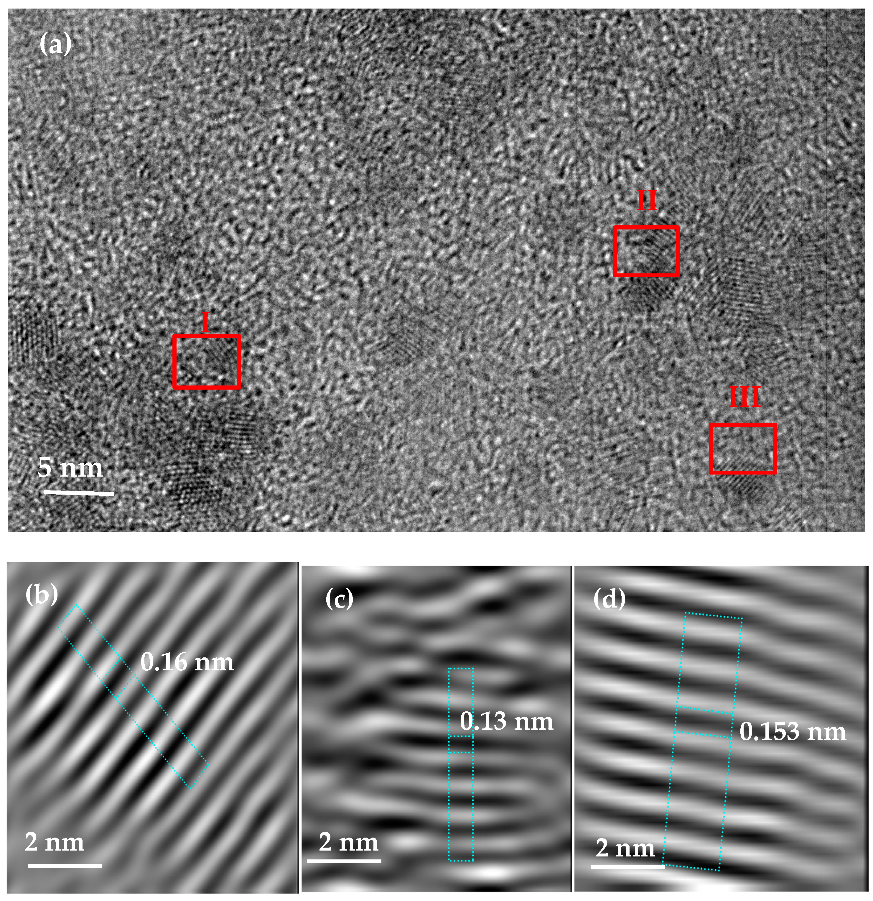
Lastly, FE-HRTEM analysis was performed to determine the surface morphologies of the catalyst Zr(x)Ni(y) and the nanocrystal structures (Figure 2). The powder consisted of nanocrystal structures corresponding to zirconium and nickel, represented in zones I, II and III. The Mire fringes with dissimilarity in the interplanar structure were identified. The d spacing was determined in nm, and the identities of each characterised element were confirmed by the XRD phases. Zone I corresponds to the d spacing of 0.14 nm, determined as the zirconium crystal (211) phase; zone II corresponds to the d spacing of 0.13 nm, determined as the nickel crystal (220) phase, as shown in Figure 2c; zone III correlates to the d spacing of the 0.15 nm/(311) phase, corresponding to the Zr2O particle, as shown in Figure 2d.

2.2. Characterisation of MgH2/10 wt.% Zr(x)Ni(y) Nanocomposite

After being activated under hydrogen, the Zr(x)Ni(y) catalyst was used as an additive in the Mg/MgH2 system. The commercial MgH2 was thus milled with 10 wt.% of Zr(x)Ni(y) for 5 h, as detailed in Section 4. The dehydrogenation properties of the formed MgH2/10 wt.% Zr(x)Ni(y) nanocomposite were analysed via temperature-programmed desorption (TPD).

2.3. Dehydrogenation Properties of the Nanocomposite MgH2/10 wt.% Zr(x)Ni(y)

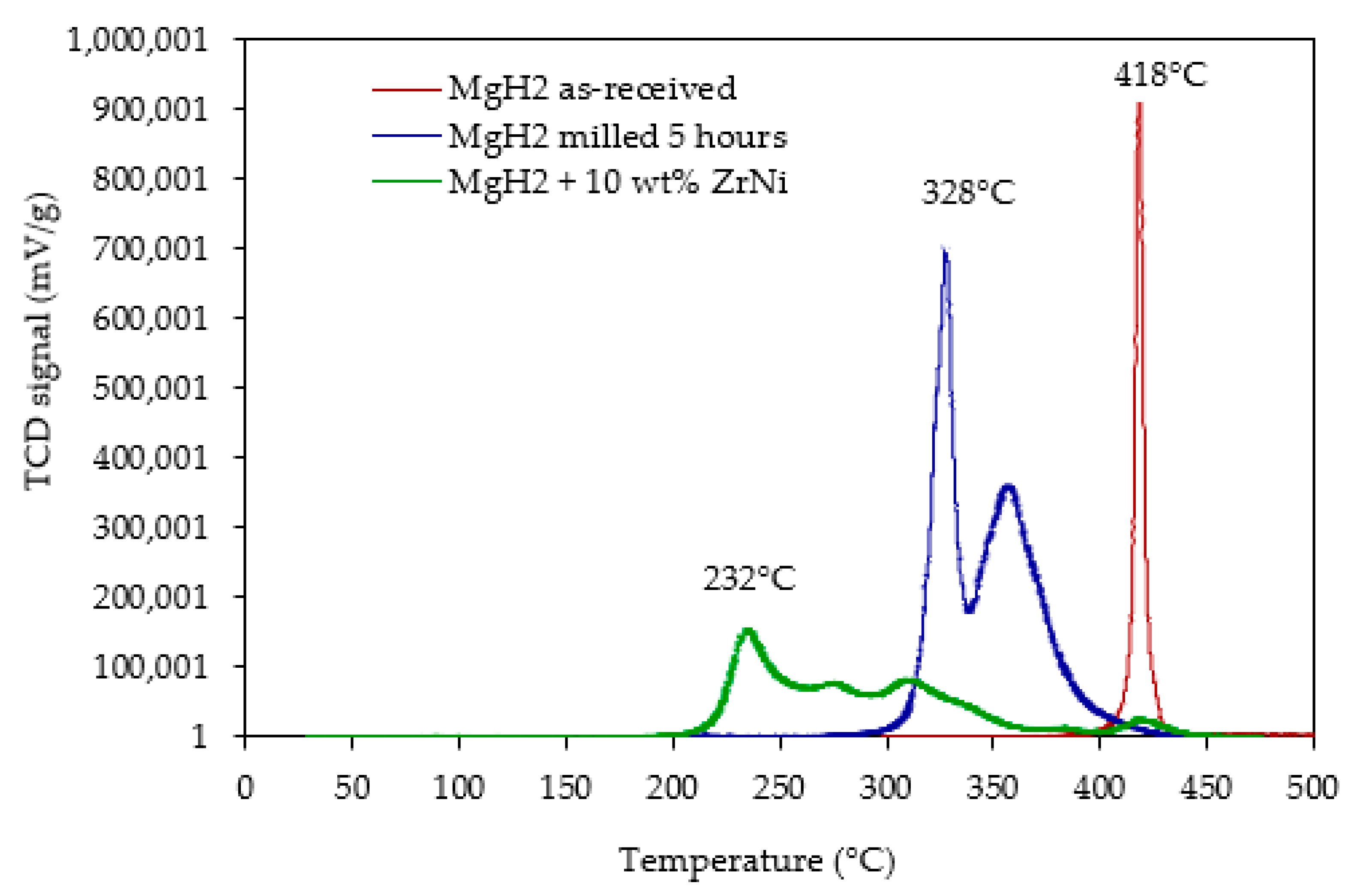
To understand how the Zr(x)Ni(y) catalyst impacts the dehydrogenation properties of MgH2, the hydrogen released properties of the nanocomposite MgH2/10 wt.% Zr(x)Ni(y) were compared with those of the as-received (un-milled MgH2) and the milled MgH2 (in similar conditions as used for nanocomposite preparation). Figure 3 represents the temperature profiles of the MgH2 decomposition, whilst Figure 4 indicates the hydrogen capacity. The milled MgH2 released 6.74 wt.% of hydrogen in a wide range of desorption temperatures between 300 °C and 400 °C, which may be a result of a large particle size distribution. It is worth noticing that the milled powder presents an important decrease in the decomposition temperature compared with the as-received powder, which is directly related to the reduction in the particle sizes of MgH2 (the mean size of crystallites was approximately 34 nm for the milled MgH2 versus approximately 213 nm for the as-received MgH2 sample, as deduced from XRD analysis by Rietveld method). The obtained result correlated with the findings reported in previous studies [22,23]. The addition of 10 wt.% Zr(x)Ni(y) nanocatalyst to MgH2 induced the shift of the onset hydrogen desorption temperature from 300 °C to a starting temperature below 210 °C. As observed for the nanocomposite MgH2/10 wt.% Zr(x)Ni(y), only 5.9 wt.% of hydrogen was released in a wide range of temperatures between 200 °C and 400 °C. This result was expected due to the high amount of additive used (10 wt.% of Zr(x)Ni(y)), which reduced the overall storage capacity of the system. To evaluate the effect of temperature on the discharge characteristics of the sorption materials, the desorption kinetic rates of MgH2 as-received (un-milled), MgH2 (milled 5 h) and MgH2/10 wt.% Zr(x)Ni(y) (milled 5 h) were calculated from the TPD curves of Figure 3, at peak desorption temperatures of 418 °C, 328 °C and 232 °C, respectively; these are shown in Table 2.

2.4. Characterisation of Crystal Structures

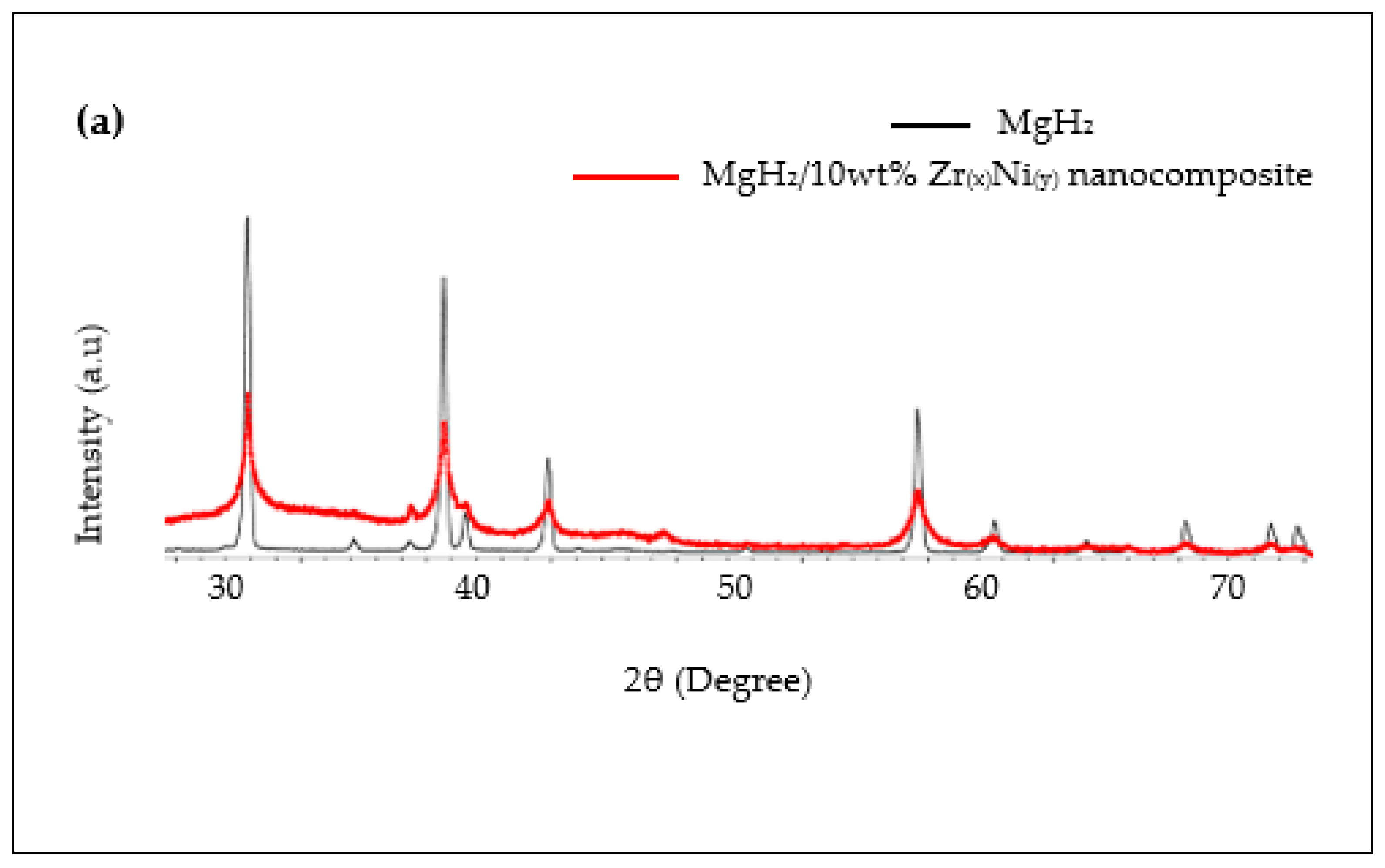
XRD was carried out to quantify the compositions of the crystalline phases of the composite after the milling process with MgH2 powder. The patterns of the composite MgH2/10 wt.% Zr(x)Ni(y) were superimposed on the reference MgH2 (un-milled) powder to reveal broadening in the diffracted line of the nanocomposite sample, which resulted from the grain refining of the powders during the planetary ball milling process (refer to Figure 5a). The composite powder obtained after 5 h milling in an inert atmosphere consisted of the Bragg peaks β-ΜgH2 (PDF file #: 00-012-0697) at 2θ of 27.95°, 35.74°, 39.86° and 54.62°; Ni (PDF file #: 00-001-1258) at 2θ of 44.37° and 51.60°; Mg0.996Zr0.004 (PDF file #: 01—71-9629) at 2θ of 32.23°, 34.42°, 36.67°, 47.88°, 57.480°, 63.13°, 67.45° and 68.75°. There was a small fraction of fcc-MgO observed at 2θ of 43.04°. The powder was mainly oxidised as a result of the sample preparation for the X-ray analysis handled outside the glove box, as shown in Figure 5b, although a low amount of MgO was also revealed in the as-received MgH2.
The SEM was used to determine the distribution of the catalyst on the surface of magnesium and to determine the size of the particles. There is a homogenous distribution of the catalyst particles, zirconium and nickel, which can be well distinguished from the SEM image, as seen in Figure 6a. The SEM image of the milled MgH2 powder used as a reference is shown in Figure 6b. The SEM image of the nanocomposite MgH2/10 wt.% Zr(x)Ni(y) in Figure 6c shows the distribution of the catalyst on the surface and edge of the MgH2 matrix. The zirconium particles are the white spots, with an average particle size of 10 nm in diameter, as shown in Figure 7a. This correlates with the study reported by El-Eskandarany et al. [15] where the milled Zr2Ni alloy powder agglomerated to form particle sizes of approximately 8 nm in diameter. The average particle size of nickel is 100 nm in diameter, as shown in Figure 7b. The wide range of MgH2 particle size distribution of the composite MgH2/10 wt.% Zr(x)Ni(y) is below 1000 nm, as shown in Figure 7c. Pighin et al. [13] reported a study of a MgH2/10 wt.% Zr8Ni21 alloy. They established that the white spots were the result of the elastic collisions of the backscattered electrons with the heavy nuclei of zirconium, considering smaller particle sizes under 1000 nm, whereas the grey region, as shown in Figure 6c, was reported to occur due to the light nuclei of magnesium hydride [13]. Figure 6d shows the zoomed image of the MgH2/10 wt.% Zr(x)Ni(y) nanocomposite, which represents the catalyst aggregation on the surface MgH2 matrix. The effect of powder aggregation was reported in previous study to be the result of the high concentration of magnesium deposited at or near the edges of the catalyst [6]. Figure 6e represents the smooth surface of the matrix corresponding to MgO that formed during the handling of the powder outside the glove box.
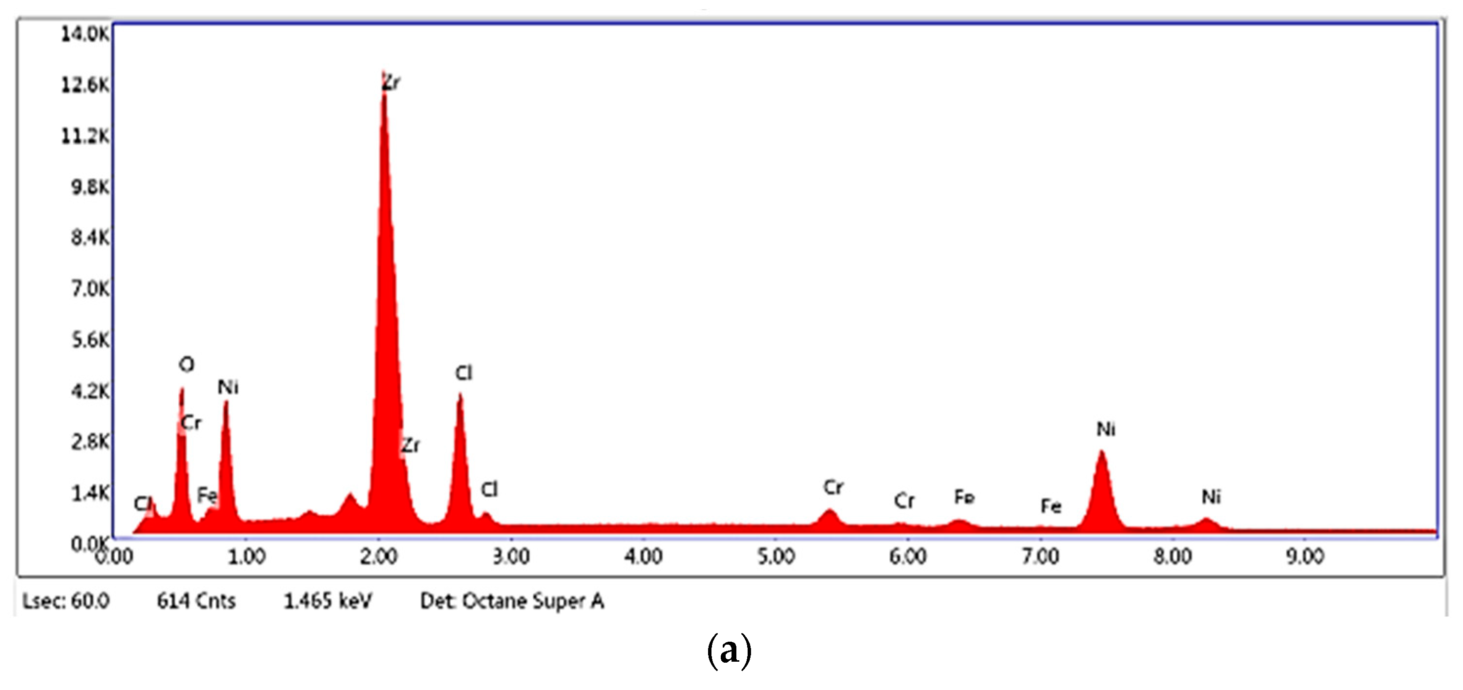
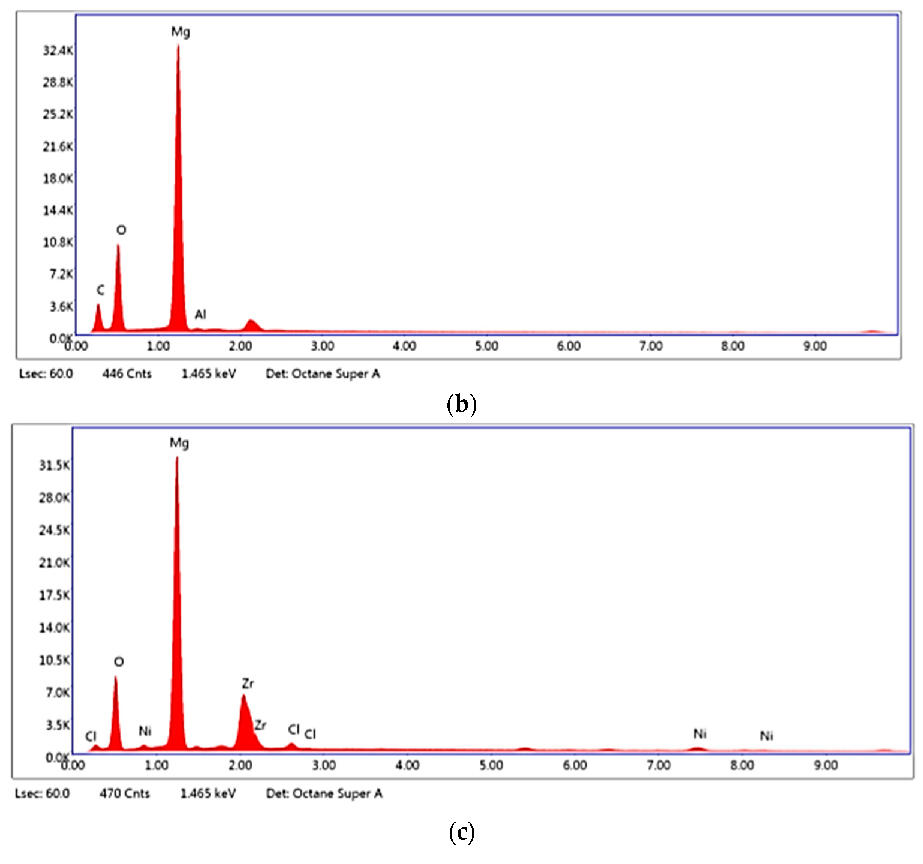
The EDX was used to confirm the presence of the analysed elements and impurities. Figure 8a shows the activated Zr(x)Ni(y) based nanocatalyst. The presence of impurities such as chlorine (Cl) came from the starting precursor material ZrCl4 powder. Figure 8b shows the presence of magnesium in the milled MgH2. Figure 8c shows the presence of magnesium, zirconium and nickel particles in the MgH2/10 wt.% Zr(x)Ni(y) nanocomposite. The additional peaks are gold (Au), from the coating during the sample preparation of the SEM analysis; carbon (C) from the carbon tape; oxygen (O) from preparing the sample outside the gloves box, and iron (Fe) from the reactor during the milling process.
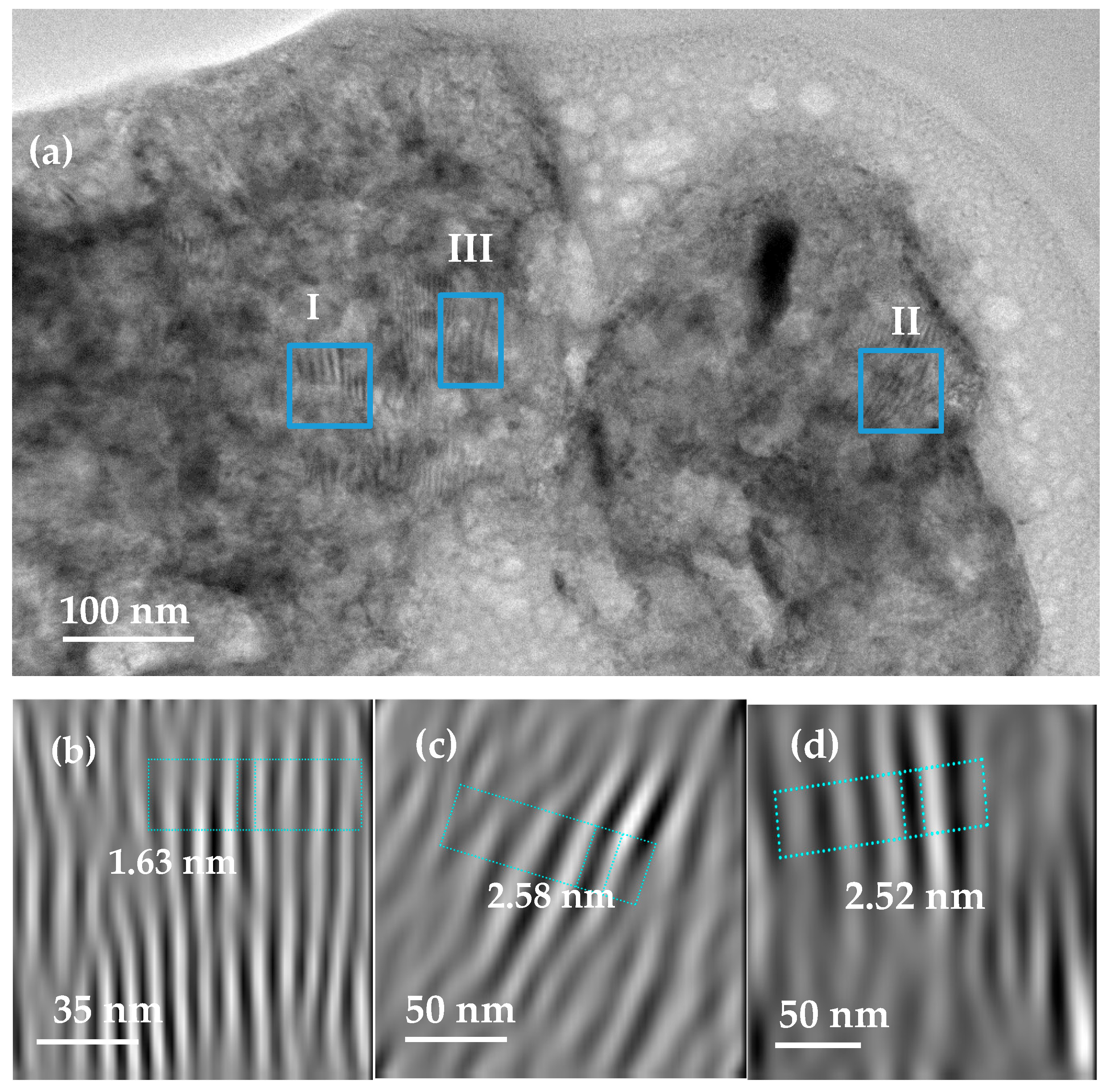
The TEM analysis was performed to determine the surface morphologies of the composite MgH2/10 wt.% Zr(x)Ni(y) on a nanometre scale and to understand the catalytic effect of Zr(x)Ni(y) on the dehydrogenation properties of MgH2 powder. The TEM image of the composite can be seen in Figure 9a, where the atomic array with a long-range ordered crystal structure is represented in the three zones. Zone I corresponds to the d spacing of 1.63 nm in Figure 9b and correlates with the (Mg0.996Zr0.004) (110) phase. Zone II corresponds to the d spacing of 2.58 nm, as shown in Figure 9c, which correlates with the (Mg0.996Zr0.004) (002) phase. Zone III is confirmed by the d spacing of 2.52 nm, as shown in Figure 9d, which correlates with the nanocrystalline β-MgH2 grain and is well-matched with the tetragonal-MgH2 (101) phase. In Figure 10, the darker particles show the agglomeration of the metallic powder Zr(x)Ni(y) based nanocatalyst on the surface of the MgH2 matrix after milling with the catalyst. Nickel particles are the dark grey elements covering the surface of the magnesium matrix, and the small, darkest spots are the zirconium particles. The agglomeration of the Zr(x)Ni(y) was also observed in a previous study, where a heterogeneous distribution catalyst on the surface of the MgH2 powder was reported [15].

3. Discussion and Conclusions

With the aim of improving the kinetic and thermodynamic properties of the Mg/MgH2 hydrogen storage system, Zr(x)Ni(y) catalyst was synthesised via a modified sol-gel method, in a compact high-pressure hydrogen reactor, and activated prior to being used as an additive to MgH2. The TPD results confirmed that the addition of Zr(x)Ni(y) to MgH2 induced an important shift towards the lower hydrogen desorption temperature. This positive impact may be due to several factors. First of all, the activation of the catalyst prior to the milling process with the MgH2 metamorphosed the alloys into fine powders; as a result, this generated a more homogeneous catalyst distribution [14]. The grain size reduction of the current catalyst was confirmed by the SEM image analysis. The reported size of the zirconium particles in the present study agreed with a number of literature reports [15] and was up to ten times smaller in comparison to the report by Pighin et al. [13]. Although the SEM and TEM analyses confirmed that the catalyst is heterogeneously distributed, it aggregates with a high concentration at the surface and near the edges of the MgH2 power. The TEM micrograph in Figure 9a shows that the catalyst covered the surface of the MgH2 during the milling process. The efficiency of the ball milling procedure in dispersing the Zr(x)Ni(y) nanocatalyst on the MgH2 was also reported by M.S. El-Eskandarany et al. [6]. Additionally, because of the ductility differences between Zr(x)Ni(y) and MgH2 particles, the efficiency of the MgH2 ball milling preparation increases in the presence of the catalyst [24,25].
The combinative impact of MgH2 crystal size reduction and Zr(x)Ni(y) nanocatalyst dispersion at the surface of MgH2 particles dramatically enhances the dehydrogenation properties in comparison with pure-milled MgH2, as shown in Figure 3, and the results from the literature using different Zr(x)Ni(y) catalysts are listed in Table 3. This is likely to be due to the presence of zirconium oxide in the starting Zr(x)Ni(y) catalyst, as confirmed in the XRD analyses of Figure 1. Indeed, ZrO2 has been recognised in the past as a transition metal oxide catalyst with the advantage of reducing the activation energy and the crystalline size during the ball milling process [25,26]. In addition, I.Yu. Zavaliy et al. [27] compared the hydrogenation of Zr3V3Ox to the ZrV2H4.9 catalysts and reported that the zirconium based oxygen catalyst increased the hydrogen storage capacity. However, the presence of ZrO2 in the MgH2/Zr(x)Ni(y) composite does not explain the differences to results from literature on its own.
The XRD results presented in Figure 5 show the presence of a new Mg0.996Zr0.004 phase formed during the milling process; this phase may impact the thermodynamic properties of the Mg/MgH2 system. In a previous study reported by Galey et al. [9], the presence of a Mg0.992Ni0.008 phase in a Mg/MgH2 system doped with a nickel complex reduced the overall hydrogenation and dehydrogenation enthalpies of the formed composite from ±75 to ±65 kJ mol−1 H2. The presence of the new phase is particularly remarkable as the destabilisation of MgH2 is the main obstacle to overcome in order to allow the use of Mg/MgH2 system at moderate temperatures. Despite the important number of studies devoted to the activation of MgH2, to date, very few researchers have succeeded in modifying its thermodynamic properties.
Although not studied here, the Zr(x)Ni(y) alloy is likewise expected to have a positive effect on the hydrogenation properties of the Mg/MgH2 system. Undoubtedly, the presence of the nanocatalyst sites well dispersed on the Mg particles may allow for the splitting of the hydrogen molecules into hydrogen atoms as well as their adsorption, followed by the subsequent migration of hydrogen atoms onto the adjacent Mg surface via spillover and further surface diffusion [15].
In summary, a novel approach was proposed for the fabrication of the catalyst Zr(x)Ni(y) by a high-pressure reactor. The approach demonstrates that mixing such nanocatalysts with MgH2 via the ball milling process offers promising perspectives. The developed method is a faster and promising approach for the fabrication of catalysts, as it is beneficial in terms of producing nanoparticle materials for improving the hydrogenation/dehydrogenation processes in future work. Therefore, there is work to be done to ameliorate the fabrication of the catalyst, such as conducting a number of experiments to find out if avoiding the presence of oxygen formation may ameliorate the work of the catalyst and further improve the kinetic and thermodynamic properties of hydrogen storage.

4. Materials and Methods

4.1. Catalyst Synthesis

The catalyst was firstly prepared in the high-pressure reactor PARR 5500 Series Compact Reactor, from a mixture of the starting material of ZrCl4 fine white powder with a 99.5+ metal basis and Ni(NO3)2.6H2O (98% green salt) provided by Alpha-Aesar and Sigma-Aldridge, respectively. The solution, 0.99 wt/v.% ZrCl4 and 1.52 wt/v.% Ni(NO3)2·6H2O, dissolved at room temperature in 150 mL of methanol solvent, was transferred into the reactor vessel (Type 316/austenitic chromium-nickel stainless steel containing molybdenum). The reactor was assembled and tightened vigorously to avoid the pressure drop of the hydrogen. The reactor vessel was purged with hydrogen for several minutes to flush out the air inside the reactor and refill it with hydrogen. The mixture was heated for 2 h at 200 °C under hydrogen, at a starting pressure of 20 bar, whilst stirring at 60 resolutions per minute. The sample was cooled overnight; the supernatant was discarded, whilst the formed gel was dried overnight at room temperature. The sample was fully dried when heat-treated at 350 °C for 5 h and further cooled for 2 h under the flow of hydrogen at 0.6 bar (Figure 11). The prepared catalyst was transferred to the glove box, purged with Argon, then transferred into the reactor vessel for activation via a particulate system HPVA at 30 °C/10 bar.

4.2. Preparation of MgH2-Based Nanocomposite Powders

The MgH2/Zr(x)Ni(y) composite was prepared under an inert argon atmosphere via the planetary ball miller using a PM100 apparatus from Retsch. A total of 10 wt.% of the hydrogenated Zr(x)Ni(y) based nanocatalyst was added to MgH2 in a reactor vessel with zirconium dioxide (ZrO2) milling balls of 1-mm diameter. The ball to powder mass ratio was 100:1. The reactor was hermetically sealed inside the glove box to prevent any oxidation of the powders. The sample was milled for 5 h at a frequency of 300 revolutions per minute. During the milling process, the rotation of the ball in the mill was paused every 2 min and inverted every 5 min to prevent the increase of temperature in the milling cell. For comparison, MgH2 was milled under the same conditions but without the addition of the catalyst.

4.3. Sample Characterisations

The properties of the synthesised catalyst and the formed composites were studied through X-ray diffraction (XRD). The crystal structures of all samples were investigated by the XRPD Bruker D8 Advance X-Ray Powder Diffractometer (XRPD) with the CuKα (λ = 0.154 nm) radiation over the 2θ ranging from 20° to 80°. The instrument was calibrated with the LaB6 NIST standard (660a). The specific surface area of the synthesised catalyst was measured with nitrogen gas (NOVAtouch LX1, USA) at a temperature of 77 Kelvin. The surface area was determined according to the Brunauer–Emmett–Teller (BET) equation.
The surface morphologies were obtained with a field emission scanning electron microscope (FESEM) (SUPRA 35VP, Zeiss, Germany). Energy dispersive X-ray spectroscopy (EDS) was used for elemental analysis of the deposited layers. For the SEM analysis, the powder placed on a carbon tape was firstly coated with the addition of a thin layer of gold, added through vacuum evaporation to prevent the sample from developing high conductivity and some charging effects during the analysis.
The TEM model JE M-2100F microscope was used for the structural features. The powder was suspended in EtOH and drop-cast onto holey carbon support film, Cu 200 mesh. The surface morphologies of the analysed powders were determined via the field emission scanning electron microscope (FESEM) (SUPRA 35VP, Zeiss, Germany). The images were collected using Gatan software.

4.4. The Dehydrogenation Behaviour

The dehydrogenation properties of the composite MgH2/10 wt.% Zr(x)Ni(y) were studied after the Zr(x)Ni(y) catalyst activation under 10 bars of hydrogen at 30 °C for 100 min. Temperature-programmed desorption (TPD) analyses were performed with a TPD/R/O-1100 apparatus from Thermo. To prevent oxidation, all the handlings were performed in a glove box under a protective argon atmosphere. The experiments were performed from ambient temperature to 500 °C at 2 °C min−1 under an argon flow of 20 mL min−1. To determine the amount of hydrogen desorbed by the samples, the instrument was calibrated prior to the analyses by the reduction of different masses of copper (II) oxide.

Author Contributions

Conceptualization, G.S. and Z.D.; methodology, G.S., Z.D. and B.G.; validation, Z.D., B.G. and G.P.; writing—original draft preparation, G.S.; supervision, Z.D. All authors have read and agreed to the published version of the manuscript.

Funding

This research received no external funding.

Conflicts of Interest

The authors declare no conflict of interest.

References

  1. Aguey-Zinsou, K.F.; Ares-Fernández, J.R. Hydrogen in magnesium: New perspectives toward functional stores. Energy Environ. Sci. 2010, 3, 526–543. [Google Scholar] [CrossRef]
  2. Sadhasivam, T.; Kim, H.T.; Jung, S.; Roh, S.H.; Park, J.H.; Jung, H.Y. Dimensional effects of nanostructured Mg/MgH2 for hydrogen storage applications: A review. Renew. Sustain. Energy Rev. 2017, 72, 523–534. [Google Scholar] [CrossRef]
  3. Zhang, X.X.; Liu, Y.; Zhang, X.X.; Hu, J.; Gao, M.; Pan, H. Empowering hydrogen storage performance of MgH2 by nanoengineering and nanocatalysis. Mater. Today Nano 2019, 9, 100064. [Google Scholar] [CrossRef]
  4. Matar, S.F. Intermetallic hydrides: A review with ab initio aspects. Prog. Solid State Chem. 2010, 38, 1–37. [Google Scholar] [CrossRef]
  5. El-Eskandarany, M.S. Metallic glassy Zr70Ni20Pd10 powders for improving the hydrogenation/dehydrogenation behavior of MgH2. Sci. Rep. 2016, 6, 1–13. [Google Scholar] [CrossRef]
  6. El-Eskandarany, M.S.; Shaban, E.; Al-Matrouk, H.; Behbehani, M.; Alkandary, A.; Aldakheel, F.; Ali, N.; Ahmed, S.A. Structure, morphology and hydrogen storage kinetics of nanocomposite MgH2/10 wt% ZrNi5 powders. Mater. Today Energy 2017, 3, 60–71. [Google Scholar] [CrossRef]
  7. Wang, Y.; Wang, Y. Recent advances in additive-enhanced magnesium hydride for hydrogen storage. Prog. Nat. Sci. Mater. Int. 2017, 27, 41–49. [Google Scholar] [CrossRef]
  8. El Khatabi, M.; Naji, S.; Bhihi, M.; Benyoussef, A.; El Kenz, A.; Loulidi, M. Effects of double substitution on MgH2 hydrogen storage properties: An Ab initio study. J. Alloys Compd. 2018, 743, 666–671. [Google Scholar] [CrossRef]
  9. Galey, B.; Auroux, A.; Sabo-Etienne, S.; Dhaher, S.; Grellier, M.; Postole, G. Improved hydrogen storage properties of Mg/MgH2 thanks to the addition of nickel hydride complex precursors. Int. J. Hydrogen Energy 2019, 44, 28848–28862. [Google Scholar] [CrossRef]
  10. Zaluska, A.; Zaluski, L.; Ström–Olsen, J.O. Nanocrystalline magnesium for hydrogen storge. J. Alloys Compd. 1999, 288, 217–225. [Google Scholar] [CrossRef]
  11. Zaluski, L.; Zaluska, A.; Ström-Olsen, J.O. Hydrogen absorption in nanocrystalline Mg2Ni formed by mechanical alloying. J. Alloys Compd. 1995, 217, 245–249. [Google Scholar] [CrossRef]
  12. Jain, I.P.; Lal, C.; Jain, A. Hydrogen storage in Mg: A most promising material. Int. J. Hydrogen Energy 2010, 35, 5133–5144. [Google Scholar] [CrossRef]
  13. Pighin, S.A.; Capurso, G.; Lo Russo, S.; Peretti, H.A. Hydrogen sorption kinetics of magnesium hydride enhanced by the addition of Zr8Ni21 alloy. J. Alloys Compd. 2012, 530, 111–115. [Google Scholar] [CrossRef]
  14. Dehouche, Z.; Peretti, H.A.; Hamoudi, S.; Yoo, Y.; Belkacemi, K. Effect of activated alloys on hydrogen discharge kinetics of MgH2 nanocrystals. J. Alloys Compd. 2008, 455, 432–439. [Google Scholar] [CrossRef] [Green Version]
  15. El-Eskandarany, M.S.; Al-ajmi, F.; Banyan, M. Mechanically-Induced Catalyzation of MgH2 Powders with Zr2 Ni-Ball Milling Media. Catalysts 2019, 9, 382. [Google Scholar] [CrossRef] [Green Version]
  16. Nei, J.; Young, K.; Regmi, R.; Lawes, G.; Salley, S.O.; Ng, K.Y.S. Gaseous phase hydrogen storage and electrochemical properties of Zr8Ni21, Zr7Ni10, Zr9Ni11, and ZrNi metal hydride alloys. Int. J. Hydrogen Energy 2012, 37, 16042–16055. [Google Scholar] [CrossRef]
  17. El-Eskandarany, M.S.; Al-Matrouk, H.; Behbehani, M.; Shaban, E.; Alkandary, A.; Aldakheel, F.; Al-Saidi, M. Amorphous-versus big cube-Zr2Ni for improving the kinetics of hydrogenation/dehydrogenation behaviors for MgH2powders. Mater. Chem. Phys. 2018, 203, 17–26. [Google Scholar] [CrossRef]
  18. Molinas, B.; Ghilarducci, A.A.; Melnichuk, M.; Corso, H.L.; Peretti, H.A.; Agresti, F.; Bianchin, A.; Lo Russo, S.; Maddalena, A.; Principi, G. Scaled-up production of a promising Mg-based hydride for hydrogen storage. Int. J. Hydrogen Energy 2009, 34, 4597–4601. [Google Scholar] [CrossRef]
  19. Ruiz, F.C.; Castro, E.B.; Peretti, H.A.; Visintin, A. Study of the different ZrxNiy phases of Zr- based AB2 materials. Int. J. Hydrogen Energy 2010, 35, 9879–9887. [Google Scholar] [CrossRef]
  20. Nei, J.; Young, K.; Salley, S.O.; Ng, K.Y.S. Effects of annealing on Zr8Ni19X2(X = Ni, Mg, Al, Sc, V, Mn, Co, Sn, La, and Hf): Hydrogen storage and electrochemical properties. Int. J. Hydrogen Energy 2012, 37, 8418–8427. [Google Scholar] [CrossRef]
  21. Parayil, S.K.; Psota, R.J.; Koodali, R.T. Modulating the textural properties and photocatalytic hydrogen production activity of TiO2 by high temperature supercritical drying. Int. J. Hydrogen Energy 2013, 38, 10215–10225. [Google Scholar] [CrossRef]
  22. Galey, B.; Auroux, A.; Sabo-Etienne, S.; Grellier, M.; Postole, G. Enhancing hydrogen storage properties of the Mg/MgH2 system by the addition of bis(tricyclohexylphosphine)nickel(II) dichloride. Int. J. Hydrogen Energy 2019, 44, 11939–11952. [Google Scholar] [CrossRef]
  23. Zhang, Q.; Zang, L.; Huang, Y.; Gao, P.; Jiao, L.; Yuan, H.; Wang, Y. Improved hydrogen storage properties of MgH2 with Ni-based compounds. Int. J. Hydrogen Energy 2017, 42, 24247–24255. [Google Scholar] [CrossRef]
  24. Galey, B.; Auroux, A.; Sabo-Etienne, S.; Grellier, M.; Dhaher, S.; Postole, G. Impact of the addition of poly-dihydrogen ruthenium precursor complexes on the hydrogen storage properties of the Mg/MgH2 system. Sustain. Energy Fuels 2018, 2, 2335–2344. [Google Scholar] [CrossRef]
  25. Chen, B.H.; Chuang, Y.S.; Chen, C.K. Improving the hydrogenation properties of MgH2 at room temperature by doping with nano-size ZrO2 catalyst. J. Alloys Compd. 2016, 655, 21–27. [Google Scholar] [CrossRef]
  26. Dong, J.; Panda, S.; Zhu, W.; Zou, J.; Ding, W. Enhanced hydrogen sorption properties of MgH2 when doped with mechanically alloyed amorphous Zr0·67Ni0.33 particles. Int. J. Hydrogen Energy 2020. [Google Scholar] [CrossRef]
  27. Zavaliy, I.Y. Effect of oxygen content on hydrogen storage capacity of Zr-based h-phases. J. Alloys Compd. 1999, 291, 102–109. [Google Scholar] [CrossRef]
Figure 1. The XRD patterns of Zr(x)Ni(y) based nanocatalyst.
Catalysts 10 00849 g001
Figure 2. Field emission high resolution transmission electron microscopy (FE-HRTEM). (a) Zr(x)Ni(y) nanocatalyst, (b) the lattice image of zone I; (c) the lattice image of zone II; (d) the lattice image of zone III.
Catalysts 10 00849 g002
Figure 3. The evolution of the temperature-programmed desorption (TPD) profile of as-received MgH2 after milling without/with 10 wt.% Zr(x)Ni(y). Experimental conditions: from ambient temperature to 500 °C under an argon flow of 20 mL min−1 and at a heating rate of 2 °C min−1.
Catalysts 10 00849 g003
Figure 4. Thermally programmed H2 desorption capacity curves of studied powders. Same experimental conditions as given in Figure 3.
Catalysts 10 00849 g004
Figure 5. The XRD patterns of (a) 10 wt.% Zr(x)Ni(y) nanocomposite in red and the un-milled MgH2 used as reference in black and (b) MgH2/10 wt.% Zr(x)Ni(y) nanocomposite to identify the crystal phase of each element.
Catalysts 10 00849 g005aCatalysts 10 00849 g005b
Figure 6. SEM micrograph of (a) Zr(x)Ni(y) based nanocatalyst after 5-h heat treatment under hydrogen; (b) MgH2 after 5 h milling time under argon, here used for reference; (ce) MgH2/10 wt.% Zr(x)Ni(y) nanocomposite. The homogeneous distributions of the Zr(x)Ni(y) on the MgH2 surface are shown in (c). The enlarged image of the MgH2/10 wt.% Zr(x)Ni(y) showing the aggregation of Zr(x)Ni(y) is represented in (d) and the presence of MgO is represented in (e).
Catalysts 10 00849 g006
Figure 7. Histograms of particle size distribution measured by the SEM/ImageJ analysis. (a) Zr; (b) Ni size distribution within the catalyst sample; (c) milled MgH2.
Catalysts 10 00849 g007
Figure 8. The energy dispersive X-ray spectrocopy (EDX) of (a) Zr(x)Ni(y) nanocatalyst; (b) milled-MgH2 as reference; (c) MgH2/10 wt.% Zr(x)Ni(y) nanocomposite.
Catalysts 10 00849 g008aCatalysts 10 00849 g008b
Figure 9. Field emission high resolution transmission electron microscopy (FE-HRTEM) of (a) MgH2/10 wt.% Zr(x)Ni(y) nanocomposite; (b) the lattice image of zone I; (c) the lattice image of zone II; (d) the lattice image of zone III.
Catalysts 10 00849 g009
Figure 10. TEM of the bright field image of MgH2 powders milled with 10 wt.% Zr(x)Ni(y), demonstrating the agglomeration of catalyst on the surface of the MgH2 matrix after 5 h milling time.
Catalysts 10 00849 g010
Figure 11. The steps of synthesis of the catalyst preparation.
Catalysts 10 00849 g011
Table 1. U.S. Department of Energy (DOE) target requirements for on-board hydrogen storage systems versus Mg/MgH2 storage properties, adapted from [1].
MgH220202025Ultimate
Gravimetric capacity (H2-wt.%)7.64.55.56.5
Volumetric capacity kg H2 L−11.40.030.040.05
Operating temperature (max/min) °C>250−40/85−40/85−40/85
Storage system cycle life (cycles)1500150015001500
Charging rate-filling time for 5 kg of H2 (min)-3–53–53–5
Storage system cost ($/kg H2)Meet target333300266
Table 2. Desorption kinetic properties of pure MgH2 as-received (un-milled), MgH2 (ball-milled 5 h) and MgH2/10 wt.% Zr(x)Ni(y). The samples were analysed via TPD from room temperature to 500 °C under an argon flow of 20 mL min−1 and at a heating rate of 2 °C min−1.
Samples Peak Desorption Temperature (°C)Discharge Rate (H-wt.% min−1)Discharge Capacity (H-wt.%)
MgH2 as-received (un-milled)4181.517
MgH2 (milled 5 h)3280.176.7
MgH2/10 wt.% ZrNi 2320.075.9
Table 3. Dehydrogenation properties of various ball milled MgH2 nanocomposites in comparison to the results obtained in the present study.
Elements Peak Desorption Temperature °CH2-wt.%References
10 wt.% Zr(x)Ni(y)2325.9Present study
10 wt.% Zr0.67Ni0.333255.0Dong et al. [26]
10 wt.% Zr8Ni213005.9Pighin et al. [13]
10 wt.% ZrNi52755.3El-Eskandarany et al. [6]
10 wt.% Zr9Ni112505.9Dehouche et al. [14]