Article

Electro-Absorbers: A Comparison on Their Performance with Jet-Absorbers and Absorption Columns

by
Monserrat Castañeda-Juárez
1,†,
Martín Muñoz-Morales
2,†,
Fernanda Lourdes Souza
2,*,
Cristina Sáez
2,
Pablo Cañizares
2,
Perla Tatiana Almazán-Sánchez
3,
Ivonne Linares-Hernández
1 and
Manuel Andrés Rodrigo
2,*
1
Instituto Interamericano de Tecnología y Ciencias del Agua, Universidad Autónoma del Estado de México, Km.14.5, carretera Toluca-Atlacomulco, San Cayetano, Toluca C.P. 50200, Estado de México, Mexico
2
Department of Chemical Engineering, Faculty of Chemical Sciences & Technologies. Universidad de Castilla La Mancha, Campus Universitario s/n, 13071 Ciudad Real, Spain
3
CONACyT-Instituto Nacional de Investigaciones Nucleares. Departamento de Química. Carretera México-Toluca S/N, La Marquesa, Ocoyoacac C.P. 52750, Estado de México, Mexico
*
Authors to whom correspondence should be addressed.
Both authors contribute equally.
Catalysts 2020, 10(6), 653; https://doi.org/10.3390/catal10060653
Submission received: 23 May 2020 / Revised: 4 June 2020 / Accepted: 9 June 2020 / Published: 11 June 2020
(This article belongs to the Special Issue Green Catalysts: Application to Waste and Groundwater Treatment)

Abstract

:
This work focuses on the removal of perchloroethylene (PCE) from gaseous streams using absorbers connected with electrolyzers. Two types of absorption devices (jet absorber and absorption column) were compared. In addition, it has been evaluated the different by-products generated when a simultaneous electrolysis with diamond anodes is carried out. PCE was not mineralized, but it was transformed into phosgene that mainly derivates into carbon tetrachloride. Trichloroacetic acid was also formed, but in much lower amounts. Results showed a more efficient absorption of PCE in the packed column, which it is associated to the higher gas–liquid contact surface. Jet absorber seems to favor the production of carbon tetrachloride in gaseous phase, whereas the packed column promotes a higher concentration of trichloroacetic acid in liquid. It was also evaluated the scale up of the electrolytic stage of these electro-absorption devices by using a stack with five perforated electrode packages instead of a single cell. Clarification of the effect of the applied current density on the speciation attained after the electrolysis of the absorbent has been attempted. Experiments reveal similar results in terms of PCE removal and a reduced generation of gaseous intermediates at lower current densities.

Graphical Abstract

Highlights
-
Significant differences in the speciation related to the absorption step.
-
PCE was not mineralized but transformed into other products.
-
Phosgene and carbon tetrachloride are the main products with the jet absorber.
-
Trichloroacetic acid is important when using the absorption column.
-
Scale up of electro-absorption with a stack cell was evaluated.

1. Introduction

In recent years, many studies have been carried out to evaluate the removal of persistent pollution from water and wastewater, but a reduced attention has been paid to the vapors emitted during these treatments [1,2]. However, gaseous pollutants are considered an important problem for the environment and for the human health [3,4], and their removal is really a matter of a major importance. In this context, gaseous emissions associated to these streams in food waste treatments plants have been studied over last decades, developing technologies capable to remove compounds, such as methyl mercaptan [5], hydrogen sulfide, and trimethylamine [6,7], typically associated with odor. Among them, it is important to highlight technologies such as thermal oxidation, selective catalyst reduction, chemical scrubbing, bioscrubbing, and biofiltration [8,9]. However, these technologies have shown several disadvantages, such as catalyst deactivation and high operating costs [10]. For this reason, other technologies such as scrubbing are gaining relevance, although it is important to take in mind that this absorption process does not attain a complete removal but it only promotes the transference of the gaseous pollutants into a liquid stream that needs for further treatment [11]. In these systems, the mass transfer is a key aspect and efficiency is controlled by residence times and gas–liquid contact surfaces, so that a design with good hydrodynamic behavior is required using high and wide contactors [6,12,13,14].
Considering this necessity, recently [15], it was proposed the use of a jet absorber to promote the gas–liquid contact in the treatment of a perchloroethylene stream. This system is based on the venturi effect and avoid the use of a compressor, allowing an important reduction in the energy requirement [16]. Obviously, this technique need to be combined with another destructive technology to remove the pollutant from the liquid [17]. In this line, one of the options is the electrochemical technology in which an electrochemical cell is combined with the absorption system in order to regenerate an active catalyst in aqueous solution [18,19] or to produce an oxidant from salts such as phosphate [10] or sulfate [20], which have been applied successfully to remove different gaseous pollutants.
Because of their good physical properties, such as low flammability, chemical stability, and an excellent washing solvent, PCE is frequently used in commercial processes such as machine manufacturing, metal degreasing, and dry cleaning. As a result, many cases of PCE-contaminated groundwater, soil [21], and indoor air of different stages of a wastewater treatment plant (WWTP) has been reported. Considering its high toxicity, volatility, extremely persistence in the environment, as well as the toxic reaction intermediates generated, such as phosgene, chloroform, and carbon tetrachloride, PCE presents in water and/or air must be removed. Among the technologies developed to eliminate PCE from liquids, it is worth to mention photocatalytic degradation [22], dielectric barrier discharge plasma [23], phytoremediation [24], sonochemical degradation [25], electrochemical degradation [26], sonoelectrochemical degradation [27,28], adsorption/electrolysis [29], etc. However, these technologies are not valid for gaseous flows where, on contrary, the wet absorption process could be considered as convenient and an economical technology. However, preliminary evaluation of these coupled technologies with jet absorber showed a production of a vast number of intermediates, mainly in the gaseous phase when PCE is used as a model compound with a negligible concentration of carbon dioxide in comparison with intermediates as trichloroacetic acid or carbon tetrachloride [15].
This work focuses on the comparison of the reactivity of gaseous PCE when it is absorbed using a jet absorber and packed absorption column, coupled with an electrolyzer. In addition, two types of electrolyzers were coupled, being one of them a single cell and the other a cell stack with five electrodes. With this comparison it was tried to determine if the bottleneck of the scale up is associated to the efficiency of electrochemical devices.

2. Results and Discussion

2.1. Absorption Using a Packed Column and Jet Absorber

To determine the absorption capacity of the two absorbers evaluated in this work, a single absorption process was carried out in the proposed set-ups. To do this, PCE concentrations in liquid and gaseous phases were measured in both liquid waste desorption (LWD) and absorbent–electrolyte storage (AES) tanks. Thus, in Figure 1, it can be seen the changes in the concentration of the PCE in the tank where the simulated gaseous pollutant was produced (Part a) and in the tank that it is contained the absorbent (Part b). As can be observed, the decay of PCE in the liquid phase of LWD tank depends on the aeration and absorber used. Thus, in the system equipped with an air compressor and the packed absorption column, PCE concentration decreases up to 95%, whereas the system equipped with the jet absorber is only capable to reduce the concentration ~35% after the same operation time (120 min). The effect of PCE condensation into the compressor was discarded in the results obtained with previous experiments taking some gaseous samples before and after this equipment for two hours obtaining no relevant differences in the mass balance of PCE. Thereby, the stripped PCE is transferred to the liquid circuit, where it is absorbed. The concentration of PCE absorbed reaches a maximum and, then, it starts to decrease. This seems to indicate that PCE is transformed into other products, whose relevance will be discussed afterwards. These results indicate that the absorption attained by the jet absorber is less efficient than that of the packed column and this observation can be explained considering two main factors, the higher gas–liquid surface area attained in the packed column because of the addition of solid spheres and the higher counter current gas flow promoted by the compressor installed (almost the double than in the jet absorber). In both systems, amounts of PCE in the gas phase are less important than in the liquid phase, but higher and fast absorption of PCE avoids the total degradation of this compound before the electrooxidation processes and this seems to point out an evolution of the system towards a different gas-liquid equilibrium.

2.2. Performance of Electro-Absorbers

Once it was determined the higher efficiency of the packed column in terms of absorbing the PCE released from the wastewater, it was necessary to determine the viability of the electrochemical process to modify the composition of the pollutants absorbed. Thus, in Figure 2, it is shown the changes in the removal of PCE (in terms of aggregated values of liquid and gaseous phases) in both tanks of the two systems, during absorption (ABS) or electro-absorption (EABS) tests.
As it can be seen, in the liquid waste desorption (LWD) tank, over the complete test in the system equipped with the packed column absorber no differences are observed with the application of current to the electrochemical cells. On contrary, minor differences appear in the removal of PCE when jet absorber was used. During the electrochemical process, a faster depletion of PCE was observed during the first 30 min. However, after this initial change, the response is stabilized in similar values of those attained by the non-electrochemical absorption process.
In the tank containing the absorbent (AES tank), there are important differences between both absorption systems. In the case of the jet absorber, evolution in the concentration of PCE is totally different, although it increases quickly at the beginning in both systems: in the single absorption was obtained almost 30% of PCE recovery at the end, and in the electroabsorption process, the evolution of the PCE decreased to detect ~5% of PCE volatilized. This behavior would be influenced by the reactivity promoted by the electrochemical process during the absorption. Regarding to the process carried out with packed column absorber, the same trends are observed in both cases, with fast absorption of PCE at the early values, but less than 15% of PCE absorbed at the end. Results confirm that the liquid-gas contact is more efficient in the column absorber and indicates that the effect of the electrochemical reactions in the global process is not as important as in the case of jet absorber.
During the absorption processes, several by-products were detected by HPLC, related with the removal pathway followed in aqueous solutions. One of them is the trichloroacetic acid (Figure 3) that corresponds to an acidic compound derived of the single displacement of a chloride radical from the PCE and the hydroxyl radicals obtained in the electrode surface [30,31], as it is shown in the Equations (1)–(4).
Cl +   OH * ClO + Cl * + H + + e
    C 2 Cl 4 + OH * + Cl *     C 2 Cl 5 O
Cl 5 O Cl *   C 2 Cl 4 O
  C 2 Cl 4 O   Cl *   C 2 HCl 3 O 2
This intermediate was detected in both tanks, which means that just the instability of PCE in water promotes this compound. However, the total amount detected in LWD tank is lower than 5 mg with soft increasing trends with the time. In the absorbent tank, higher concentration is detected during both electro-absorption processes, which means that the secondary products generated in the electrooxidation could promote also an hydrogenolysis that increase the total concentration of this intermediate. Trichloroacetic acid, due to its high polarity and low vapor pressure, is commonly found in liquid phase. Thereby, the higher generation also in the system equipped with the jet absorber suggests that an important transformation of PCE is transferred directly to the liquid phase which makes it easier the further pollution removal [32].
Another intermediate detected by HPLC analysis is the carbon tetrachloride, and its behavior is shown in Figure 4. This compound shows similar concentrations in the waste and the absorber tanks, being undetectable in the waste tank (LWD) when the jet absorber system without electric current was used. Its formation can be explained in terms of the decomposition of phosgene, which is an intermediated known to be produced by wet hydrolysis of PCE [33]. This compound behaves as a final product because no decreasing trends were obtained with the time and it was produced without remarked differences in both ABS and EAB processes.
Both intermediates—carbon tetrachloride and trichloroacetic acid—were the unique compounds detected and quantified by HPLC, but they represent different removal pathways of PCE related to the higher gas–liquid contact or to the promoted attack of strong oxidants generated during the electrooxidation. However, mass balance informs about the existence of a third compound with absorption at 365 nm [34] and with a ratio chlorine/carbon 2:1, which is not detected by GC or HPLC. This information is compatible with the formation of phosgene, an organic compound produced by wet hydrolysis of PCE [33,35]. Figure 5 shows the amount of phosgene estimated by carbon-mass balance. As can be observed, there is a clear difference in the evolution of phosgene in tests carried out with the jet absorber and the packed column. In the electro-absorption with jet aerator, the concentration of phosgene is negligible which agrees with the higher efficiency showed in the PCE recovery and the use of electrooxidation with diamond electrodes. Regarding the Jet ABS, although the evolution of phosgene seems higher than the process applying current density, at the end, similar concentration was reached which shows that phosgene generation is not very influenced by the presence of the electrolytic processes. On the other hand, the evolution of phosgene was similar in the Column ABS and Column EABS processes, but it was very different in comparison with Jet ABS and Jet EABS, reaching a total mass around 5 times higher. This behavior is associated to the different absorption setups used and the different pathways that control the depletion of PCE in each absorption process.
Once it was monitored the main products obtained, different removal pathways of the degradation of PCE could be proposed. The distribution of these compounds detected at the end of the process is shown in Table 1. It is highlighted that only carbon dioxide was detected after the absorption with the Jet ABS, but also in this set-up was obtained the lower removal of PCE. The most effective system for the removal of PCE was the packed column (7.89–9.21%, respectively). However, in the case of jet absorber, it is shown a high concentration of trichloroacetic acid in Jet EABS test. In recent studies [23,36] it was reported the mechanism of oxidation of PCE to trichloroacetic acid, as well as the formation chlorine radicals that can attack to the carbon cleavage of the PCE to form phosgene. This compound is unstable and could be degraded into carbon tetrachloride and carbon dioxide.

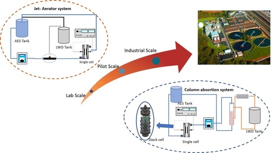
2.3. Scale up of Electro-Absorption Processes

To evaluate the scale up of the electrolytic process, the system equipped with the packed column absorber was selected for an additional study, due to its better performance. In this new study, the single cell was replaced by a stack of cells. Figure 6 shows the total mass of PCE (sum of liquid and vapor phase) and by-products generated during the electro-absorption process, as a function of current density applied after a treatment of 2 h. The total mass of PCE does not vary with the current density used in the electrochemical process. In fact, it is nearly depleted. Surprisingly, TCA is only observed at low concentrations, which may indicate a different performance of the stack with this product as compared with the single electrolyzer. The main products are phosgene and CCl4. However, substantial modifications were observed in their distribution. As can be seen, at low current densities, the main final reaction product is phosgene, remaining in solution around 200 mg after the treatment. When the current density increases, CCl4 becomes the primary final product (up to 450 mg), which it is probably motivated by the side reactions that occurs in the electrode surface due to the limitations of mass transfer. Nevertheless, in this point it is important to point out that this figure compares results which correspond to different electric charged passed, because the electrolysis times in all experiments were the same. Thus, the higher is the current density applied, the higher is the electric charge supplied in each test and, hence, the progress of the electrochemical reaction. Therefore, despite having used the same treatment times, results may be indicating that phosgene is produced previously to carbon tetrachloride and not the real effect of the current density.
To clearly see this effect, it is necessary to compare results obtained at the same electric charge passed. This can be seen in Figure 7, in which all tests were compared for an applied electric charge of 0.35 Ah dm−3 and where it can be seen that higher current densities are less efficient in the degradation of PCE, which can be explained in terms of the promotion of side reactions such as water oxidation and reduction. Meanwhile, low current densities promote the formation of phosgene. The amounts of CCl4 produced do not depend on the current density, being the key product in all tests. The relevance of TCA is very low and limited to the application of low current densities.
In this way, this study indicates that the electro-absorption using a cell stack could be a feasible technology to achieve good PCE oxidation. However, further research should be developed due to no complete elimination of its by-products was attained. No phosgene was found at the end of the process, although significant concentrations of carbon tetrachloride remain in solution mainly when higher current densities are applied. Thereby, it is important to warn about the toxicity of phosgene and the reduction of their concentration, which is a considerable achievement of the electrochemical technology. However, the removal of carbon tetrachloride that is a recalcitrant by-product would be in subsequent studies the real challenge to achieve a complete mineralization.

3. Materials and Methods

3.1. Chemicals

All chemical reagents, including perchloroethylene (C2Cl4 > 99%) (a.r., Sigma-Aldrich, Darmstadt, Germany), anhydrous sodium sulfate, phosphoric acid (85%), sulfuric acid (99.8%), sodium carbonate (a.r., Fluka, Madrid, Spain), were analytical grade and used as received. Hexane HPLC grade (a.r., Sigma-Aldrich, Darmstadt, Germany) was used as mobile phase in gas chromatography. Helium and nitrogen (Air Liquide España, S.A. Madrid, Spain) were used in gas chromatography, and helium was filtered by a Hydrocarbon Cartridge Filter (Thermo Fisher Scientific, Madrid, Spain) before its use. Double deionized water (Millipore Milli-Q system, resistivity = 18.2 MΩ cm at 25 °C) was used to prepare all solutions.

3.2. Experimental Setup

Absorption and electro-absorption processes were developed in the two versatile set-ups shown in Figure 8: one in that integrates a jet absorber (part a) and another that integrates an absorption packed column (part b). Both experimental systems are divided into two connected circuits: the liquid (absorbent–electrolyte) circuit and the gas circuit. In both cases, there is a tank (liquid waste desorption (LWD) tank, (4) where the raw concentrated solution (1 L of aqueous solution with 150 mg dm−3 of perchloroethylene (PCE)) is stored. From here, the volatilization and stripping of PCE is induced by a gas flow.
The jet absorber is based on the venturi effect and it is used to create suction favoring the flow of gas from tank 4 into the liquid circuit. Therefore, the stripping of the PCE from the LWD tank (4) is promoted. The small throat diameter of the jet (4.23 mm) modifies the size of the bubbles generated, affecting to the behavior of the absorption process. Additionally, to ensure good mixing conditions in tank 4, a magnetic stirrer (5) was used [15]. In the other system (Figure 1b), the gas phase is generated with an air compressor (Silent Pump (11) model SI6000, ICA SA, Toledo-Spain) with 3.8 W and a flowrate of 360 L h−1. This gas stream passes through the LWD tank (4), favoring the stripping of PCE and then it flows through the absorption packed column (10) where it is transferred to liquid circuit. Gas and liquid phases flow countercurrent in the column. The absorption column is made of glass with 0.5 m long and an inner diameter of 500 mm. A length of 0.4 m of the column was packed with glass spheres (8 mm ± 0.75). These spheres are solid (2.5g cm−3) made of high-quality borosilicate glass which are a good choice for demanding corrosive environments. Therefore, the role of tank 4 in both cases is to produce a more realistic gaseous pollutant flow, with real gaseous mixtures water-PCE, which can influence on the later treatment because of the reactivity of PCE in wet environments [37].
On the other hand, the liquid phase (electrolyte solution with the PCE absorbed) is pumped with a centrifugal pump (1) to the electrochemical cell (7), which is connected to a power supply (8) and where the degradation of the species present in the liquid phased occurs. Additionally, in this system conventional electrochemical cell is modified to test the scale up of the process using a stack of cells (12) model ECWP d20X5P. (Condias GmbH, Itzehoe, Germany) The absorbent-electrolyte storage (AES) tank (9) is the auxiliary tank of the electrochemical cell in both setups. Its function is to provide residence time to the electrochemical cell in order to promote chemical reactions mediated by oxidants or reductants generated by the application of the electric current. In both systems, there is a connection between the AES and LWD tanks (9 and 4) to equilibrate the total pressure of the system.
Both the AES tank (6) and LWD tank (4) were made of polyvinyl chloride (PVC) with capacities of 2.5 L and 1.2 L, respectively. Sample points are implemented in both tanks. The liquid phase used as absorbent was an aqueous solution of Na2SO4 (0.1 mol L−1). The centrifugal pump is a Micropump® GB-P25 J F5 S (flow rate 160 L h−1) supplied by Techma GPM s.l.r. (Milan, Italy) connected to the electrochemical cell by a Tecalan® tube. Extreme care was taken to avoid gaseous losses in all compartments by using tight-fitting ground silicone stoppers and by sealing with Teflon tape.
To study and compare the two absorption systems proposed in terms of absorption and depletion of PCE, experiments were performed for 120 min collecting samples in duplicated at specified time intervals.
Electrochemical processes were conducted with two kind of commercial electrochemical cells: The first one was a DiaCell® supplied by Adamant Technologies (La Chaux-de-Fonds, Switzerland), in which conductive diamond electrodes (p-Si–boron-doped diamond) were used as anode and cathode, respectively. Both electrodes were circular (100 mm diameter) with a geometric area of 78.6 cm2. The BDD coating have a 2–3 µm of the thickness, boron concentration 500 ppm, and the relation sp3/sp2 > 150. The active surface is 78.6 cm2 and the inter electrode gap is 1 mm. The stack of cells selected for the scaleup was a CondiaCell® model ECWP d20X5P supplied by Condias GmbH (Itzehoe, Germany) consisting of ten circular stainless steel electrodes as cathodes with 20 × 1.5 mm and five circular Diachem® type perforated electrodes as anode. These diamond electrodes (50 × 24 × 1.3 mm3) were built on a substrate that consists of a niobium mesh (type B) and were assembled in two stacks with a NAFION® cation exchange membrane separating the anode and cathode and acting as the electrolyte [38]. The anodic active area per package is approximately 420 mm2 and the inter electrodes gap is 0.5 mm. Four current were studied being 0.8, 4.4, 8, and 16 A. Both kinds of electrodes were subjected to cleaning procedure during 10 min in a 1 M Na2SO4 solution at 15 mA/cm2 prior to electrolysis assays. All the processes were conducted at room temperature (20 ± 2 °C) and at atmospheric pressure conditions.

3.3. Analysis Procedures

Liquid and gas samples were taken from two different sampling ports which are placed in the accumulation and PCE tanks. To determine and quantify PCE concentration in gas and liquid phase, it has been followed the procedure described elsewhere [15,39].
For the determination of by-products produced in the absorption and electro-absorption treatment, two chromatographic methods were employed: The first one was used to analyze carbon tetrachloride by means Jasco HPLC LC-2000 with a PDA MD-2018 Detector (Jasco, Tokio, Japan). The mobile phase consisted of an aqueous solution of 0.1% of phosphoric acid (flow rate of 1.0 mL min−1). The detection wavelength used was 280 nm and the temperature of the oven was maintained at 25 °C. Volume injection was set to 20 μL. The second method was used to analyze trichloroacetic acid, which was determined using a HPLC Agilent 1100 series (Agilent Tech. Santa Clara, CA, USA) with a detection wavelength of 220 nm. The ion exchange column used was SupercogelTM H Column with 30 cm × 7.8 mm ID. The mobile phase: 1% phosphoric acid (H3PO4), column temperature: 30 °C, flow rate: 0.8 mL/min, injection volume: 20 μL.

4. Conclusions

From this work, the following conclusions can be drawn.
  • Both jet absorbers and packed column absorbers can be used for the absorption stage of the removal of PCE with electro-absorbers. Packed columns reached more successful results.
  • The column absorber favors the formation of trichloroacetic acid.
  • Electrooxidation process with diamond electrodes increases the reduction of PCE but enhances the generation of more dangerous and toxic intermediates. Trichloroacetic acid and carbon tetrachloride are the main compounds detected. A removal pathway for PCE degradation related to the absorption efficiency in both set-ups can be proposed.
  • The use of a cell stack with five electrodes does not show remarkable differences in the removal efficiency of PCE as compared to the singles cell. However, TCA formation is not promoted with the scaled-up system. In addition, current density affects importantly to results. Low current densities lead to the formation of higher amounts of phosgene and higher current densities to the less efficient removal of PCE.

Author Contributions

M.C.-J.: Investigation, Data curation, Methodology Writing—review and editing. M.M.-M.: Investigation, Data curation, Methodology, Writing—review and editing. F.L.S.: Writing—review and editing, Methodology. C.S.: Supervision, Writing—review and editing, P.C.: Funding acquisition, Supervision, P.T.A.-S.: Writing—review and editing, I.L.-H.: Funding acquisition, Supervision. M.A.R.: Review and editing, Funding acquisition, Validation, Supervision. All authors have read and agreed to the published version of the manuscript.

Funding

This research was funded by Spanish Agencia Estatal de Investigación through projects CTM2016-76197-R and PID2019-107271RB-I00, and by CAPES (88881.171154/2018-01) and CONACyT.

Acknowledgments

Financial support from the Spanish Agencia Estatal de Investigación through project CTM2016-76197-R (AEI/FEDER, UE) is gratefully acknowledged. This work is also first results of the Project PID2019-107271RB-I00, continuation of the CTM2016-76197-R. Martin Muñoz-Morales acknowledges the FPU grant nº 16/0067. Fernanda L. Souza gratefully acknowledged Coordenação de Aperfeiçoamento de Pessoal de nível Superior (CAPES) process 88881.171154/2018-01 for the scholarship awarded. M. Castañeda-Juárez acknowledges the scholarship granted by CONACyT.

Conflicts of Interest

The authors declare no conflicts of interest.

References

  1. Chang, H.; Tan, H.; Zhao, Y.; Wang, Y.; Wang, X.; Li, Y.; Lu, W.; Wang, H. Statistical correlations on the emissions of volatile odorous compounds from the transfer stage of municipal solid waste. Waste Manag. 2019, 87, 701–708. [Google Scholar] [CrossRef]
  2. Wang, S.; Ang, H.M.; Tade, M.O. Volatile organic compounds in indoor environment and photocatalytic oxidation: State of the art. Environ. Int. 2007, 33, 694–705. [Google Scholar] [CrossRef] [PubMed]
  3. Schlegelmilch, M.; Streese, J.; Biedermann, W.; Herold, T.; Stegmann, R. Odour control at biowaste composting facilities. Waste Manag. 2005, 25, 917–927. [Google Scholar] [CrossRef]
  4. Dalton, P. How people sense, perceive and react to odors. BioCycle 2003, 44, 26–29. [Google Scholar]
  5. Muthuraman, G.; Chung, S.J.; Moon, I.S. The combined removal of methyl mercaptan and hydrogen sulfide via an electro-reactor process using a low concentration of continuously regenerable Ag(II) active catalyst. J. Hazard. Mater. 2011, 193, 257–263. [Google Scholar] [CrossRef] [PubMed]
  6. Govindan, M.; Chung, S.-J.; Jang, J.-W.; Moon, I.-S. Removal of hydrogen sulfide through an electrochemically assisted scrubbing process using an active Co(III) catalyst at low temperatures. Chem. Eng. J. 2012, 209, 601–606. [Google Scholar] [CrossRef]
  7. Chen, W.H.; Lin, J.H.; Lin, Y.C. A novel two-stage scrubbing technology for odor control of kitchen waste composting. Aerosol Air Qual. Res. 2012, 12, 1386–1397. [Google Scholar] [CrossRef] [Green Version]
  8. Atkinson, R.; Arey, J. Atmospheric Degradation of Volatile Organic Compounds. Chem. Rev. 2003, 103, 4605–4638. [Google Scholar] [CrossRef]
  9. Ruokojärvi, A.; Ruuskanen, J.; Martikainen, P.J.; Olkkonen, M. Oxidation of Gas Mixtures Containing Dimethyl Sulfide, Hydrogen Sulfide, and Methanethiol Using a Two-Stage Biotrickling Filter. J. Air Waste Manag. Assoc. 2001, 51, 11–16. [Google Scholar] [CrossRef]
  10. Muthuraman, G.; Thirumavalavan, M.; Il Shik, M. In situ electrochemically generated peroxymonophosphoric acid as an oxidant for the effective removal of gaseous acetaldehyde. Chem. Eng. J. 2017, 325, 449–456. [Google Scholar] [CrossRef]
  11. Govindan, M.; Adam Gopal, R.; Moon, I.S. Efficient removal of gaseous trichloroethylene by continuous feed electro-scrubbing using a new homogeneous heterobimetallic electro-catalyst. Chem. Eng. J. 2017, 308, 1145–1153. [Google Scholar] [CrossRef]
  12. Fang, P.; Cen, C.; Tang, Z.; Zhong, P.; Chen, D.; Chen, Z. Simultaneous removal of SO2 and NOX by wet scrubbing using urea solution. Chem. Eng. J. 2011, 168, 52–59. [Google Scholar] [CrossRef]
  13. Muthuraman, G.; Moon, I.-S. A review on an electrochemically assisted-scrubbing process for environmental harmful pollutant’s destruction. J. Ind. Eng. Chem. 2012, 18, 1540–1550. [Google Scholar] [CrossRef]
  14. Yang, J.; Liu, K.; Jia, J.; Cao, L. Electro-scrubbing volatile organic carbons in the air stream with a gas diffusion electrode. J. Hazard. Mater. 2011, 188, 125–131. [Google Scholar] [CrossRef]
  15. González-Pérez, O.; Muñoz-Morales, M.; Souza, F.L.; Saez, C.; Cañizares, P.; Rodrigo, M.A. Jet electro-absorbers for the treatment of gaseous perchloroethylene wastes. Chem. Eng. J. 2020. [Google Scholar] [CrossRef]
  16. Pérez, J.F.; Llanos, J.; Sáez, C.; López, C.; Cañizares, P.; Rodrigo, M.A. The pressurized jet aerator: A new aeration system for high-performance H2O2 electrolyzers. Electrochem. Commun. 2018, 89, 19–22. [Google Scholar] [CrossRef]
  17. Song, J.T.; Song, H.; Kim, B.; Oh, J. Towards Higher Rate Electrochemical CO2 Conversion: From Liquid-Phase to Gas-Phase Systems. Catalysts 2019, 9, 224. [Google Scholar] [CrossRef] [Green Version]
  18. Govindan, M.; Moon, I.-S. A single catalyst of aqueous CoIII for deodorization of mixture odor gases: A development and reaction pathway study at electro-scrubbing process. J. Hazard. Mater. 2013, 260, 1064–1072. [Google Scholar] [CrossRef] [PubMed]
  19. Chandrasekara Pillai, K.; Raju, T.; Chung, S.J.; Moon, I.-S. Removal of H2S using a new Ce(IV) redox mediator by a mediated electrochemical oxidation process. J. Chem. Technol. Biotechnol. 2009, 84, 447–453. [Google Scholar] [CrossRef]
  20. Balaji, S.; Muthuraman, G.; Moon, I. Influence of cathode on the electro-generation of peroxydisulfuric acid oxidant and its application for effective removal of SO2 by room temperature electro-scrubbing process. J. Hazard. Mater. 2015, 299, 437–443. [Google Scholar] [CrossRef] [PubMed]
  21. Muñoz-Morales, M.; Sáez, C.; Cañizares, P.; Rodrigo, M.A. Anodic oxidation for the remediation of soils polluted with perchloroethylene. J. Chem. Technol. Biotechnol. 2019, 94, 288–294. [Google Scholar] [CrossRef] [Green Version]
  22. Pitkäaho, S.; Matejova, L.; Ojala, S.; Gaalova, J.; Keiski, R.L. Oxidation of perchloroethylene—Activity and selectivity of Pt, Pd, Rh, and V2O5 catalysts supported on Al2O3, Al2O3-TiO2 and Al2O3-CeO2. Appl. Catal. B Environ. 2012, 113, 150–159. [Google Scholar] [CrossRef]
  23. Karimaei, M.; Nabizadeh, R.; Shokri, B.; Khani, M.R.; Yaghmaeian, K.; Mesdaghinia, A.; Mahvi, A.; Nazmara, S. Dielectric barrier discharge plasma as excellent method for Perchloroethylene removal from aqueous environments: Degradation kinetic and parameters modeling. J. Mol. Liq. 2017, 248, 177–183. [Google Scholar] [CrossRef]
  24. Andrew James, C.; Xin, G.; Doty, S.L.; Muiznieks, I.; Newman, L.; Strand, S.E. A mass balance study of the phytoremediation of perchloroethylene-contaminated groundwater. Environ. Pollut. 2009, 157, 2564–2569. [Google Scholar] [CrossRef] [PubMed] [Green Version]
  25. Sáez, V.; Esclapez, M.D.; Bonete, P.; Walton, D.J.; Rehorek, A.; Louisnard, O.; González-García, J. Sonochemical degradation of perchloroethylene: The influence of ultrasonic variables, and the identification of products. Ultrason. Sonochemistry 2011, 18, 104–113. [Google Scholar] [CrossRef]
  26. Sáez, V.; Esclapez Vicente, M.D.; Frías-Ferrer, Á.J.; Bonete, P.; González-García, J. Electrochemical degradation of perchloroethylene in aqueous media: An approach to different strategies. Water Res. 2009, 43, 2169–2178. [Google Scholar] [CrossRef]
  27. Sáez, V.; Esclapez, M.D.; Tudela, I.; Bonete, P.; Louisnard, O.; González-García, J. 20kHz sonoelectrochemical degradation of perchloroethylene in sodium sulfate aqueous media: Influence of the operational variables in batch mode. J. Hazard. Mater. 2010, 183, 648–654. [Google Scholar] [CrossRef]
  28. Esclapez, M.D.; Sáez, V.; Milán-Yáñez, D.; Tudela, I.; Louisnard, O.; González-García, J. Sonoelectrochemical treatment of water polluted with trichloroacetic acid: From sonovoltammetry to pre-pilot plant scale. Ultrason. Sonochemistry 2010, 17, 1010–1020. [Google Scholar] [CrossRef]
  29. Muñoz-Morales, M.; Sáez, C.; Cañizares, P.; Rodrigo, M.A. Improvement of electrochemical oxidation efficiency through combination with adsorption processes. J. Environ. Manag. 2020, 262, 110364. [Google Scholar] [CrossRef]
  30. Marco-Urrea, E.; Gabarrell, X.; Sarrà, M.; Caminal, G.; Vicent, T.; Reddy, C.A. Novel Aerobic Perchloroethylene Degradation by the White-Rot Fungus Trametes versicolor. Environ. Sci. Technol. 2006, 40, 7796–7802. [Google Scholar] [CrossRef] [Green Version]
  31. Sáez, V.; Esclapez, M.D.; Bonete, P.; González-García, J.; Pérez, J.M. Spectroelectrochemical study of perchloroethylene reduction at copper electrodes in neutral aqueous medium. Electrochim. Acta 2008, 53, 3210–3217. [Google Scholar] [CrossRef] [Green Version]
  32. Esclapez, M.D.; Tudela, I.; Díez-García, M.I.; Sáez, V.; Bonete, P. Towards the complete dechlorination of chloroacetic acids in water by sonoelectrochemical methods: Effect of the cathode material on the degradation of trichloroacetic acid and its degradation by-products. Appl. Catal. B Environ. 2015, 166–167, 66–74. [Google Scholar] [CrossRef]
  33. Meyer, R.J.; Safarik, D.J.; Reeves, C.T.; Allen, D.T.; Mullins, C.B. Phosgene formation from adsorption of carbon tetrachloride on oxygen modified Ir(111). J. Mol. Catal. A Chem. 2001, 167, 59–66. [Google Scholar] [CrossRef]
  34. Xie, H.; Wu, Y.; Zeng, F.; Chen, J.; Wu, S. An AIE-based fluorescent test strip for the portable detection of gaseous phosgene. Chem. Commun. 2017, 53, 9813–9816. [Google Scholar] [CrossRef] [PubMed]
  35. Zhang, T.; Troll, C.; Rieger, B.; Kintrup, J.; Schlüter, O.F.K.; Weber, R. Composition optimization of silica-supported copper (II) chloride substance for phosgene production. Appl. Catal. A Gen. 2009, 365, 20–27. [Google Scholar] [CrossRef]
  36. Sweeney, L.M.; Kirman, C.R.; Gargas, M.L.; Dugard, P.H. Contribution of trichloroacetic acid to liver tumors observed in perchloroethylene (perc)-exposed mice. Toxicology 2009, 260, 77–83. [Google Scholar] [CrossRef]
  37. United States Environmental Protection Agency. EPA’s Integrated Risk Information System; EPA: Washington, DC, USA, 2016.
  38. Isidro, J.; Brackemeyer, D.; Sáez, C.; Llanos, J.; Lobato, J.; Cañizares, P.; Matthee, T.; Rodrigo, M.A. Operating the CabECO® membrane electrolytic technology in continuous mode for the direct disinfection of highly fecal-polluted water. Sep. Purif. Technol. 2019, 208, 110–115. [Google Scholar] [CrossRef]
  39. Muñoz-Morales, M.; Sáez, C.; Cañizares, P.; Rodrigo, M.A. A new electrochemically-based process for the removal of perchloroethylene from gaseous effluents. Chem. Eng. J. 2019, 361, 609–614. [Google Scholar] [CrossRef]
Figure 1. Changes in the perchloroethylene (PCE) mass during the absorption using the jet absorber (■, □) and the absorption packed column (, ○) in a (a) liquid waste desorption (LWD) tank containing liquid waste polluted with PCE and (b) absorbent–electrolyte storage (AES) tank.
Catalysts 10 00653 g001
Figure 2. Evolution of PCE as a function of the time in the jet absorber system (■) and in the packed column () during the absorption (ABS) and the electro-absorption process (EABS). (a) LWD tank. (b) AES tank.
Catalysts 10 00653 g002
Figure 3. Evolution of trichloroacetic acid as a function of the time in the jet absorber system (■) and in the packed column () during the absorption (full points) and the electro-absorption process (empty points). (a) LWD tank. (b) AES tank.
Catalysts 10 00653 g003
Figure 4. Evolution of carbon tetrachloride as a function of the time in the jet absorber system (■) and in the packed column () during the absorption (full points) and the electro-absorption process (empty points). (a) LWD tank. (b) AES Tank.
Catalysts 10 00653 g004
Figure 5. Evolution of phosgene as a function of the time in the jet aerator system (■) and in the packed column () during the absorption (full points) and the electro-absorption process (empty points).
Catalysts 10 00653 g005
Figure 6. Organochlorinated compounds generated at the end of treatment during the electro-absorption technology using a Condiacell® as function of current density applied (■) PCE, () TCA, () CCl4, and () phosgene (PHG).
Catalysts 10 00653 g006
Figure 7. Influence of the current density on the products generated at 0.35 Ah dm−3 during the electro-absorption technology using a Condiacell®. (■) PCE, () TCA, () CCl4 and () phosgene (PHG).
Catalysts 10 00653 g007
Figure 8. Schematic diagram for the absorption and electro-absorption process using both setups evaluated: (a) jet-absorber and (b) absorption packed column. (1) Pump. (2) Rotameter. (3) Jet-aerator. (4) Liquid Waste desorption (LWD) tank. (5) Magnetic stirrer. (6) Sampling point. (7) Electrochemical cell. (8) Power supply. (9) Absorbent electrolyte storage (ABS) tank. (10) Glass packed column. (11) Air-compressor silent pump. (12) Stack of cells model ECWP d20X5P.
Catalysts 10 00653 g008
Table 1. Distribution of intermediates in carbon conversion percentage at the end of the treatment with the different technologies proposed.
Degradation Compounds(1)(2)(3)(4)
carbon tetrachloride11.16%14.45%11.41%12.49%
trichloroacetic acid2.79%20.34%3.22%6.46%
phosgene9.15%16.07%77.47%71.83%
perchloroethylene59.78%49.14%7.89%9.21%
carbon dioxide17.12%0.00%0.00%0.00%
(1) Absorption with jet absorber (Jet ABS), (2) Electro-absorption with jet absorber (Jet EABS), (3) Absorption with packed column (Column ABS), (4) Electro-absorption with packed column (Column EABS).

