Abstract
This work proposes to use core-shell structured spheres to evaluate whether it allows to individually optimize bulk and surface effects of a packing material, in order to optimize conversion and energy efficiency. Different core-shell materials have been prepared by spray coating, using dense spheres (as core) and powders (as shell) of SiO2, Al2O3, and BaTiO3. The materials are investigated for their performance in CO2 dissociation and compared against a benchmark consisting of a packed-bed reactor with the pure dense spheres, as well as an empty reactor. The results in terms of CO2 conversion and energy efficiency show various interactions between the core and shell material, depending on their combination. Al2O3 was found as the best core material under the applied conditions here, followed by BaTiO3 and SiO2, in agreement with their behaviour for the pure spheres. Applying a thin shell layer on the cores showed equal performance between the different shell materials. Increasing the layer thickness shifts this behaviour, and strong combination effects were observed depending on the specific material. Therefore, this method of core-shell spheres has the potential to allow tuning of the packing properties more closely to the application by designing an optimal combination of core and shell.
1. Introduction
A dielectric barrier discharge (DBD) reactor is a popular type of plasma reactor used for a variety of reactions, including both decomposition and synthesis reactions [1,2,3,4]. It is flexible in use, i.e., power, frequency, pressure, discharge gap, reactor shape, and flow patterns can be varied, and it can also be easily upscaled and implemented for industrial use [3]. The performance of a DBD reactor can be improved by adding a packing material to the reaction zone to obtain higher conversions, selectivities, and/or energy efficiencies compared to the standard empty DBD reactor [1,2,5,6,7]. Adding a packing material to the reaction zone will induce both physical and chemical changes, resulting in a wide variety of outcomes [4,8]. On one hand, the packing material will change physical aspects such as the gas flow behaviour through the reactor–by reducing the discharge volume to small voids between the spheres, altering the flow and mixing patterns, and reducing the residence time–as well as the characteristics of the plasma and the discharging behaviour. The properties of the packing material, i.e., size and shape, dielectric constant, (elemental) composition, surface roughness, thermal and electrical properties, porosity, etc., can influence the type of discharge, electron temperature and density, surface losses, etc. [8,9,10]. We can differentiate the effects of material properties into bulk and surface effects, e.g., dielectric constant and electrical conductivity are bulk effects, while surface roughness and adsorption are surface effects. On the other hand, the reactive plasma can influence the packing materials as well, both on a short and long term. Short term effects include the generation of a direct flux of excited species, radicals, or ions towards the surface, lowering the activation barrier, and changing reaction pathways; long term effects are alterations to the material structure, such as changing oxidation states, etching/destruction of the surface/pores, and/or inactivation of doped catalysts [8]. Furthermore, the gas mixture itself will influence the plasma characteristics, and requires specific conditions as well for optimal transfer of electrical energy in chemical energy. It is therefore not at all straightforward to correlate any cause and effect, when introducing and comparing different packing materials.
When searching for the best packing material, using pure, dense bulk materials quickly hits some obstacles, as each material has its fixed and specific properties that cannot be changed individually at the surface and in the bulk. Moreover, changing the material type varies several of the above-mentioned parameters (both physical and chemical; and both surface and bulk), that impact the plasma behaviour and surface chemistry at the same time. Indeed, in our previous work we investigated millimetre-sized spheres from different materials in a packed-bed DBD reactor for both CO2 dissociation (acting as benchmark in this work as well) and dry reforming of methane (DRM), and we found it was not a straightforward method to pinpoint the exact origin of the observed effects [5,6,11]. Additionally, using exactly the same reactor with different operating parameters renders different results [5,6]. Hence, in order to be able to better tune a packing material, combining different properties in bulk (physical) and surface (physical-chemical) behaviour might be needed for optimal performance. The combination of these properties might, however, not be present in one type of material. Therefore, we evaluate in this paper the potential of using millimetre-sized core-shell structured spheres. These spheres consist, as the name implies, of a dense spherical core that is covered with a (thin) shell (of 50 to 500 µm thickness). The core will mainly determine the bulk effect of the entire sphere such as dielectric constant, thermal and electrical properties; while the shell, will determine mainly the surface effects such as porosity, adsorption, (electrical) surface properties, and surface chemistry, as well as some bulk effects, if the shell is made sufficiently thick—potentially shielding core effects. With this approach, we can test a wide variety of combinations of core and shell material types, and their respective sizes, in order to evaluate the potential of core-shell materials to tune the DBD reactor performance.
Core-shell spheres have been widely used in the past, with examples found in thermal catalysis, electrocatalysis, photocatalysis, drug screening, etc. [12,13,14,15,16,17,18,19,20], and with coated pellets widely used in the pharmaceutical and food industry [21,22,23]. Usually the core-shell spheres are produced in the micro- to nanometre range via methods such as sol-gel deposition, hydrothermal synthesis, colloidal synthesis, plasma deposition, and microfluidic gelation; with only a few examples found in the millimetre-size range made by hydrothermal synthesis or spray coating [13,21,22,23,24]. Although being widely used in different fields of research and application, core-shell spheres are rarely adopted in plasma conversion processes, with only a few cases reported in literature, e.g., Zheng et al. used nano-sized core-shell particles for DRM [25,26]. Coated spheres with dispersed or clustered catalytically active materials, or nano-sized (mono) layers, have also been used in plasma reactors [27], but to our knowledge, no research has been reported using millimetre-sized core-shell spheres with systematically altered core-shell combinations of different materials as those we propose here.
This approach is evaluated for CO2 splitting into CO and O2 due to its simpler chemistry compared to multi-component mixtures, such as (dry) reforming of methane. Specifically, we will investigate the influence of adding a shell to a spherical core, and how the respective material combinations and shell thickness affect the overall performance of the DBD reactor, in terms of CO2 conversion and energy efficiency, in order to estimate its potential in design of appropriate packing materials for plasma conversion processes. The purpose is not finding the highest activity but evaluating the potential of core-shell structures to improve packed-bed plasma reactor performance.
2. Results
Before discussing the effect of using core-shell spheres with different shell thicknesses, the reference will be discussed (empty reactor and pure cores). Note that the results of the pure spheres were obtained in our previous work and are more thoroughly discussed there [5].
2.1. Benchmark Measurements for the Empty Reactor and the Reactor Packed with Pure Spheres
Figure 1a shows the results for the empty reactor at the standard conditions (denoted as “=Flow”), and a higher flow rate to obtain the same residence time (RT) as the packed reactors (denoted as “=RT”). It shows a base conversion and energy efficiency of 11% and 3.0%, respectively, for a flow rate of 38.98 mL/min (27.20 s RT); while obtaining 6.4% and 3.2%, respectively, for a flow rate of 79.96 mL/min (14.07 s RT). Note that all but one bar in Figure 1 represent both conversion and energy efficiency since they are just scaled. The measurement of the empty reactor at the same residence time (“=RT”) has two parts of which the lower part depicts the conversion and the upper part the energy efficiency.
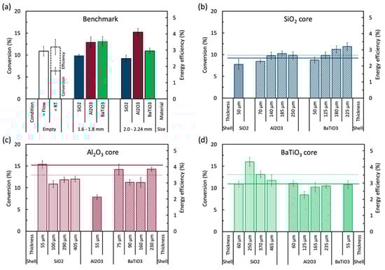
Figure 1.
Overview graph of the conversion and energy efficiency of (a) the benchmark results (i.e., empty reactor and packed reactor with pure spheres [5]), and all core-shell samples with (b) SiO2 core, (c) Al2O3 core, and (d) BaTiO3 core. All core-shell samples were coated with SiO2, Al2O3, and BaTiO3 powder in different shell thicknesses, as indicated in each figure. All measurements were performed at 30W, 38.98 mL/min, and 1 bar; except for the empty reactor, which was also evaluated at the same residence time as the packed reactors (79.96 mL/min). The dotted and solid lines are the performance of the corresponding core spheres in their small and big size, respectively. The exact values can be found in Table A1 in Appendix A.
Inserting a packing material into the discharge gap shows clear material and size dependent effects, as also shown and discussed in [5,6]. All packed reactors show better conversions than the empty reactor at the same residence time, i.e., same gas treatment time. However, when compared with the empty reactor at the same flow rate, i.e., same throughput, only the Al2O3 spheres, and the BaTiO3 spheres at 1.6 to 1.8 mm diameter perform better (both in conversion and energy efficiency). SiO2 with a size range of 1.6 to 1.8 mm shows a lower conversion of 9.8% and the larger sphere size, 2.0 to 2.24 mm, even yields a slightly worse conversion of 9.2% (within error bars). This means that SiO2 is able to enhance the electric properties of the plasma through local electric field enhancements [28], but not enough to compensate for the 48.27% reduction in reaction volume due to the spheres (see Section 4.2). Adding a packing to the reactor increases the available surface area to promote (catalytic) surface chemistry. If present, this surface chemistry can also inhibit the plasma chemistry, by losses of energetic species upon collision with the surface [29]. Al2O3, however, can compensate for the reaction volume reduction, with a conversion of 13% at a 1.6 to 1.8 mm sphere size, and 15.2% at a sphere size of 2.0 to 2.24 mm. Lastly, BaTiO3 shows an improved conversion of 13% at 1.6 to 1.8 mm sphere size, but the 2.0 to 2.24 mm spheres performed worse, with a conversion of 10.9%. These results illustrate the interaction between sphere size and material type on the conversion. Both SiO2 and BaTiO3 exhibit a slight decrease in conversion, while Al2O3 shows an increase at larger sphere size. This is consistent with the modelling work of Van Laer and Bogaerts [9], which revealed that there is not necessarily a linear correlation between dielectric constant and the plasma parameters (electric field, electron temperature, and electron density), as well as the sphere size (number of spheres in the discharge gap). The trends in energy efficiency are the same as for the conversion, which is logical when the flow rate is kept constant. More considerations about the energy efficiency will be given in Section 3 below.
Evidently, each material behaves differently based on their size, and this may be attributed to a number of material specific properties–such as dielectric constant, surface roughness, surface chemistry, electrical conductivity, heat capacity, etc., as well as the number of contact points, void space between the spheres, etc., which proved to be difficult to correlate by previous researchers [6,11]. By comparing these benchmark results with the performance of the core-shell samples in the next section, we hope to obtain some clues on the effect of the material properties with respect to their bulk or surface effect.
2.2. Core-Shell Spheres
A matrix of samples has been prepared based on three materials (SiO2, Al2O3, and BaTiO3) in different shell thicknesses to investigate the effect of the shell material, the core material, and the shell thickness, as shown in Figure 1b–d. However, for an unbiased evaluation, first we will look into the actual influence of adding a shell to the spheres, by coating them with a shell of the same material as the core material.
2.2.1. Influence of a Shell on the Performance of the Spheres
By coating the pure spheres with a thin layer of the same powderous material as the core, we can investigate how a calcined powder layer affects the performance compared to the pure spheres. Figure 2 shows the results of the pure spheres coated with a thin layer of approximately 50 µm to form a shell of the same material. As can be observed, all core-shell spheres show worse results than their pure non-coated 1.6 to 1.8 mm variants (shown as a solid line). SiO2@SiO2 has the smallest drop in conversion (i.e., 8% compared to 9.8% for the pure sphere), BaTiO3@BaTiO3 shows a somewhat larger drop in conversion (i.e., 10.8% compared to 13%), but the biggest difference is seen with Al2O3@Al2O3 where the conversion drops to 7.8% compared to 12.8% for the pure spheres. This negative effect of adding a shell of the same material may be attributed to a different morphology (i.e., macroscopic roughness, powder grain surface, introduced interstitial porosity between the grains, etc.), a negative effect of the LUDOX binder, or a masking effect by the shell for a useful property of the core, or a combination of all effects. Indeed, it has been shown that the morphology of the spheres can have a significant impact on the chemistry in plasmas [8]. This is because the morphology can enhance the local electric field by extra contact points, sharp edges, and close surfaces in for example macropores, resulting in different plasma discharges, changing the local chemistry. This may or may not have an effect on the performance, which can be either beneficial or detrimental, depending on the reactions. Additionally, the added LUDOX binder, although necessary for shaping, is an extra material added to the shell which might introduce an unknown effect on the shell performance. Binder effects are known for thermal catalysis [30,31,32], but have not yet been studied in plasma catalysis, as far as we know. It is also for this reason that we kept the amount of binder limited to 1 wt%, although we cannot exclude its effect even at these small quantities. Furthermore, as plasma can only be formed in pores with diameter larger than the Debye length, which is typically several 100 nm for DBD plasma conditions [33], most of the bulk material of the spheres might be out of reach for the reactive plasma species to promote any reaction. This means that adding a shell, although porous in nature, can shield (most of) the reactive plasma species from the core and thus inhibit any activated core surface chemistry. Apparently, this effect is more present with the Al2O3@Al2O3 spheres. Exactly the same source powder of α-Al2O3 was used to prepare the core spheres and to coat the shells, but they were subject to different synthesis processes (e.g., thermal post-treatments) and different chemicals (e.g., calcium present in the core, a silica binder in the shell). This hints that either (i) the pure Al2O3 spheres exhibit an effect that is particularly well masked by the shell, e.g., the presence of calcium compounds remaining from the synthesis (CaCO3, CaO, and/or CaO.xAl2O3 with x = 1, 2, or 6) [34]; and/or (ii) the Al2O3 powder has a large inhibiting effect as shell material, by lacking desired surface properties, having unwanted porosity, the presence of the LUDOX binder, or another, yet unidentified, aspect. This clearly indicates that a particular difference in the shell can induce physical aspects that have a relatively large impact on conversion and energy efficiency, necessitating further studies with samples that are well controlled in these properties.
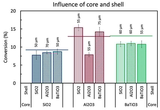
Figure 2.
Influence of the core and shell material tested by approximately 50 µm thick shells applied on different core materials. All samples are compared to the pure spheres (solid line) with 1.6 to 1.8 mm size. All experiments are performed at the standard conditions. The exact values can be found in Table A1 in the Appendix A.
2.2.2. Influence of Core and Shell Material
By applying a thin shell of approximately 50 µm on a core, we can investigate the individual effect of the shell and core material on the performance of the core-shell sphere, while minimizing extra bulk effects that may be caused by the shell. The results of a combination of SiO2, Al2O3, and BaTiO3 in Figure 2 show that no clear order in shell performance can be observed, with the exact (lack of) impact depending on the core material. The results show that there is little to no difference in performance between the different shell materials when using SiO2 cores or BaTiO3 cores, while significant differences can be observed when shells are applied on Al2O3 cores. This suggests that there are no clear surface effects of the different shell materials in the case of SiO2 cores or BaTiO3 cores and/or that the shells are too thin to have a significant influence on the bulk effects of the whole sphere. However, the Al2O3 cores show a different story, because SiO2 and BaTiO3 shells slightly improve the base conversion; but the Al2O3-Al2O3 interaction, as already seen in the previous section, clearly has a detrimental effect.
Finally, Figure 2 illustrates the influence of the core material on the core-shell spheres. The general order of performance puts Al2O3 cores on top (with the exception of Al2O3@Al2O3), followed by BaTiO3, and finally SiO2. The exception of Al2O3@Al2O3 suggests that the Al2O3 powder (hypothesis (ii) from before) is the culprit of the bad performance and that it is not a core effect. From these results so far, we can conclude that optimal core-shell spheres can be designed by using a strong base material as a core, coupled to a complementary shell material. It is important to realize, that a strong core material is not necessarily also a strong shell material, and vice versa, due to the different (surface and bulk) properties that seem to play a role, as shown by the Al2O3@Al2O3 samples. This illustrates the high potential of core-shell spheres for optimal designed packing materials.
2.2.3. Influence of Shell Thickness
Finally, we take a look at the influence of the shell thickness, illustrated in Figure 1b–d with their exact values in Table A1 in Appendix A. It is clear that the exact effect of extra shell material is very different for all core and shell material combinations. SiO2-based core-shell spheres, which have a low intrinsic performance, show to have opportunity for improvement as thicker Al2O3 and BaTiO3 shells result in higher conversion. The added amount of shell material overcomes any effect of the SiO2 cores, resulting in an almost linear increase in added performance.
This is, however, not the case with the Al2O3 and BaTiO3 based core-shell spheres where no continuous increasing or decreasing behaviour is seen in function of shell thickness for either of the added shell chemistries. This suggests a strong interaction, or even competition, between the more prominently present but shielded surface and bulk effects of the core, and increasing surface and bulk effects of the shell. A combination effect of these properties seems to be present where for example adding more SiO2 shifts the core-shell performance from pure core material (i.e., Al2O3 or BaTiO3) more towards pure SiO2, or the conversion of the BaTiO3@Al2O3 spheres shifts between pure Al2O3 and BaTiO3.
Curiously, SiO2 shells do show an optimum thickness first, but it is unknown why exactly this ‘poor behaving material’ does this and at this particular thickness. Additionally, Al2O3 shells again show deviant behaviour, i.e., the performance does not rise as much on SiO2 cores and there is low interaction with BaTiO3 cores, suggesting that the coated powder has less activity than the shaped spheres (same powder, added binders)—see Section 2.2.2. These results show that optimizing core-shell spheres by thickness is possible, but the choice of core and shell material is very important and induces important additional properties. Moreover, it clearly shows that a good core material is not necessarily also a good candidate for a shell. The use of core-shell materials will most likely mainly influence the plasma discharge properties, as they are not necessarily catalytically active, but for specific reactions, they can also promote gas-surface reactions in case of a more porous available surface.
3. Discussion
A few reflections can be made based on the results from Section 2.1 and Section 2.2. First of all, we did not find a core-shell sample with a significant performance improvement within this matrix of materials and shell thicknesses, as was also not intended. The results, however, did shed some light on the bulk and surface effects that different materials have on their performance in a DBD plasma reactor. The present data, however, do not allow us to determine the exact origins of their behaviour but do feature an impact of their relative contribution and thus importance. Better control over the material properties of the core-shell spheres is the next task to identify the underlying features of the results seen here. This requires a separate systematic, more elaborate study with much more controlled material synthesis based on the knowledge obtained in this work. Additionally, for the further development of tuned (catalytic) (core-shell) packing materials for plasma (catalysis) conversion processes, extra diagnostics would be needed to determine changes in the plasma electrical behaviour and plasma chemistry, such as optical emission spectroscopy or in-situ IR. This would allow to determine changes in the chemical species and to provide a more direct way for measuring the material effects on both the plasma gas composition and on the composition of the gas layer near, and adsorbed species on, the material surfaces (by in-situ spectroscopic measurements). This might elucidate the reactions that may occur at the surface, indicating any “catalysis”. For instance, IR diagnostics in reflection mode on the surface, i.e., DRIFTS diffuse reflectance infrared Fourier transform spectroscopy) coupled to mass spectrometry (DRIFTS-MS) was developed by Stere et al. [35] for studying plasma-catalytic reactions through observation of changes in the species at the catalyst surface. This work was the first DRIFTS hybrid plasma (DBD) system reported in literature for studying the reaction mechanism during plasma catalysis. The same group also reported another interesting in-situ diagnostic [36] for studying the role of plasma in heating on the catalyst structure, using X-ray absorption fine structure (XAFS). Azzolina-Jury and Thibault-Starzyk also applied IR diagnostics, to obtain time-resolved in-situ spectroscopic data, directly providing information about adsorbed species under plasma exposure [37,38]. Note, however, that these techniques are most sensitive to species with large surface density, which are not necessarily the most reactive species. Furthermore, some reactive intermediate species may not be detected, depending on the time resolution. In addition, fast imaging by intensified Charge Coupled Device (iCCD) cameras can be applied to study the plasma behaviour in contact with catalyst materials, and in particular the characteristics of plasma streamers propagating over catalyst surfaces [39,40,41]. Finally, plasma dynamic experiments of the spheres in a simplified and standardized packed bed set-up, such as proposed by Butterworth and Allen [42], can provide information on the changes in plasma discharging behaviour for different core-shell materials.
Besides being able to tune and optimize the bulk and surface effects of packing materials through core-shell spheres, the macroporous shell structure forms interesting opportunities for catalyst doping. It was predicted by modelling that plasma streamers can only penetrate into pores with a size larger than the Debye length [33], which is typically a few 100 nm, depending on the gas and other operating conditions. Hence, full dispersion of a catalytic compound in the entire (microporous) sphere can be a waste of valuable catalyst material. The thin shell layers produced in our work can form the perfect substrate for catalyst doping for more optimal plasma-catalyst interaction. Bulk effects of the core-shell sphere can optimize the plasma and reactive species generation via its physical impact, while the doped shell material can create the optimal accessible surface needed for catalyst reactions, with the possibility to enhance reaction pathways via the plasma-excited species.
Additionally, we recently investigated the reaction rate coefficients and equilibrium constants of CO2 dissociation, CH4 reforming, and dry reforming of methane under the influence of power, pressure, discharge gap size, and packing materials [29]. By testing packed-bed reactors over an extended residence time range, we discovered that packing materials can individually change the overall reaction rate coefficient, as well as the equilibrium position. By checking only one particular condition, a lot of possible information is lost about the exact effect of a certain type of packing material on the kinetics. Therefore, further endeavours in (catalytic) packing material development will benefit from using this type of analysis to obtain more detailed knowledge.
Finally, Figure 1 also displays the energy efficiency of the benchmark results and all core-shell samples. It shows the same trends as the conversion, since the energy efficiency is linearly proportional to the conversion when the power and flow rate are constant. The reference energy efficiency of the empty reactor was found to be only 3% for both cases, i.e., the same flow rate and same residence time as the packed reactors. Adding the pure un-coated spheres can enhance the energy efficiency, depending on the material and size combination, up to 4.1% for 2.0 to 2.24 mm Al2O3 spheres. Within the core-shell samples, only the 55 µm SiO2@Al2O3 and 250 µm SiO2@BaTiO3 can slightly enhance this energy efficiency further, although all within the same error bars. This matches the maximum values we have found before for CO2 dissociation in our previous paper on packed-bed (micro) DBD reactors [5].
4. Materials and Methods
4.1. Core-Shell Spheres
The core-shell spheres were synthesized by means of spray coating. With this method, a suspension of the desired shell material is sprayed on the cores in fine droplets, which stick to the surface, and as the solvent evaporates, it leaves a fraction of powder behind. Spraying while turning the core materials in a pan, slowly builds up a full layer over time, that can grow to a desired thickness. A calcination process was applied to fix the layer in place and remove the organic components.
The formulation of the coating suspension is the same for all core-shell combinations and was based on the coating slurry of Lefevere et al. for their 3DFD structures [43]. A mixture of distilled water, methyl cellulose as a temporary organic binder (15 cP, Sigma-Aldrich, Overijse, Belgium), and colloidal silica as a permanent binder (LUDOX HS-40, Sigma-Aldrich) was used to disperse and suspend the powderous shell material. The final composition was 1 wt% methyl cellulose, 1 wt% LUDOX, and 30 wt% shell powder. Powders made of SiO2 (0–10 µm, Sigmund Lindner, Warmensteinach, Germany), α-Al2O3 (400 nm A 16 SG, Almatis, Rotterdam, The Netherlands), and BaTiO3 (200 nm, Inframat, Manchester, Connecticut, United States) were used as the shell materials as received. For each new batch, 100 mL of bare spheres, used as the cores, were placed in a rotating bowl with agitation fins to tumble the spheres around and ensure an as even as possible coating of all spheres and sphere surface. Dense SiO2 (Type-S, Sigmund Lindner), α-Al2O3 (custom made at VITO, Mol, Belgium) [34], and BaTiO3 (Catal Ltd., Sheffield United Kingdom) spheres with a size of 1.6 to 1.8 mm were used as cores. The suspension was coated on the rotating spheres by a compressed air driven spray gun, and dried at the same time with a hot air gun. The green core-shell spheres were calcined for 4 h at 650 °C with a heating ramp of 2 °C/min. The four shell thicknesses where aimed at being 50, 100, 150, and 200 µm. Maximum layers of approximately 100 µm were applied at a time. The 150 and 200 µm coatings were done in two steps with an intermediate calcination step. In practice, deviant shell thicknesses will be obtained due to the unpredictable suspension losses during the coating process, i.e., premature drying of the sprayed droplets and abrasion losses during tumbling. The shell thickness was analysed after calcination by embedding the spheres in an epoxy resin (ClaroCit, Struers, Maassluis, The Netherlands), sanding them down until halfway the spheres, being imaged by 10x microscope (XploRa plus, Horiba Scientific, Villeneuve-d’Ascq, France), and being analysed by ImageJ (version 1.52, National Institute for Health, United States). A schematic representation of the spray coating set-up and an example of four layer thicknesses of BaTiO3@SiO2 core-shell spheres are shown in Appendix B and Appendix C (Figure A1 and Figure A2, respectively).
4.2. Experimental Set-Up
A cylindrical DBD reactor was used, as schematically shown in Figure 3. The reactor consists of an alumina dielectric tube, with a 22 mm outer diameter and inner diameter of 17 mm, which serves as the dielectric layer and outer wall of the reaction zone. A stainless-steel rod, with an 8 mm outer diameter, was placed in the centre of the tube to serve as the inner, grounded electrode and inner wall of the reactor, resulting in a discharge gap of 4.5 mm. A stainless-steel mesh, with a length of 100 mm, was wrapped around the outside of the alumina tube, acting as the high voltage electrode, resulting in a total reaction volume of 17.67 mL. The reaction volume was filled with either the reference dense spheres or synthesized core-shell spheres, which were held in place with a layer of glass wool (superfine 8 to 50 µm, Glaswarenfabrik Karl Hecht, Sondheim vor der Rhön, Germany) on both sides. The reference spheres are the same cores as in Section 4.1, in two size ranges, being 1.6–1.8 mm and 2.0–2.24 mm.
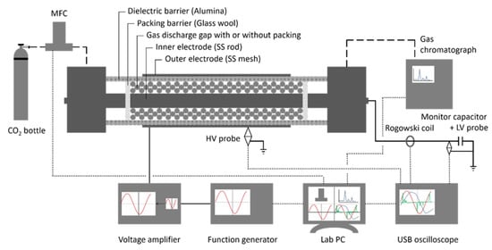
Figure 3.
Packed bed DBD plasma reactor used in this work, along with analytical equipment (reprinted from [5] with permission from Elsevier).
A pure CO2 stream was fed to the reactor via a mass flow controller. A flow rate of 38.98 mL/min was used for both empty and packed reactors, and in addition, a flow rate of 75.35 mL/min was used for the empty reactor to test the performance at equal residence time as the packed reactor at 38.98 mL/min (i.e., 14.07 s for a modelled packing efficiency of 48.27% [29]).
The reaction products were analysed by a gas chromatograph (Compact GC, Interscience, Breda, The Netherlands) with pressure-less sampling. This GC features a thermal conductivity detector (TCD) channel, able to measure the CO and O2 composition as one peak and the CO2 composition separated by an Rt-Q-Bond column. No significant amounts of ozone or carbon deposition were detected. The CO2 conversion was defined as:
where is the molar flow rate of CO2. A correction factor was applied to compensate for gas expansion in a pressure-less set-up to obtain the actual conversion [44,45]:
The power to the reactor was provided by a high voltage amplifier (model 20/20C-HS, TREK, Lockport, NY, USA), which was driven by a PC controlled function generator (AFG 2021, Tektronix, Berkshire, UK) at a frequency of 3 kHz. The applied voltage, current, and displaced charge were monitored by a high voltage probe (P6015A, Tektronix), a current transformer (model 4100, Pearson Electronics, Palo Alto, CA, USA), and a low voltage probe (TA150, Pico Technology, St. Neots, UK) paired with a monitor capacitor (10 nF), respectively. All signals were recorded with a digital oscilloscope (Picoscope 6402D, Pico Technology). The power was calculated during a number () of consecutive periods () according to:
The power was maintained at 30 W by adjusting the voltage of the function generator. Finally, the energy efficiency was calculated based on the theoretical and consumed energy as:
where is the reaction enthalpy of CO2 dissociation (279.8 kJ/mol), is the volumetric flow rate, is the plasma power, and is the molar gas volume (22.4 L/mol). The ratio of the plasma power over the volumetric flow rate is also known as the specific energy input or :
4.3. Experimental Method
Each experiment was started with a freshly packed, cooled-down reactor and operated for 40 min to achieve steady state conversion. The amplitude of the input voltage was continuously adjusted to deliver the desired power of 30 W during this stabilisation, which was followed by the GC and Lissajous measurements.
Each packing material was tested in threefold with four GC and Lissajous measurements for statistical analysis. The error on the resulting average is defined as:
where is the sample standard deviation of the measurements, is the sample size being 12, and is the two-tailed inverse of the Student t-distribution for sample size and probability set at 95%.
The standard operating conditions used in this work were a pure CO2 stream with a flow rate of 38.98 mL/min, performed at 30 W (3 kHz), and 1 bar in a discharge gap of 4.5 mm. This results in an average residence time of 14.07 s and a specific energy input (SEI) of 46.18 J/mL in the packed reactors. Some of these parameters were varied, as specified in the results section.
5. Conclusions
In this paper we investigated the potential of core-shell structured spheres as packing materials in a DBD reactor, for plasma-based CO2 conversion. Core-shell spheres have the potential to be tailored to a specific reaction, requiring weak/strong bulk/surface effects, potentially in combination with a catalytically active material for optimal performance. First of all, we found that applying a thin shell layer of approximately 50 µm of the same material as the core significantly reduces the performance of the packing material, indicating that the shell might mask the positive effect of the core and/or induced negative effects due to certain shell properties. Combining different materials showed various interactions between the core and shell material, affecting the conversion. Al2O3 was found to be the best core material, followed by BaTiO3 and SiO2, in agreement with the behaviour of the pure spheres. It was also found that all three shell materials perform equal in low amounts (thin shell), with the exception of Al2O3@Al2O3, and that they are not able to provide any significant improvement. A strong mixing behaviour is seen where more active shell materials can improve weak core materials, but will have to compete against strong core materials to show their effect on the performance.
Our results show that surface and bulk effects can have different influences on the performance of the spheres in a plasma reactor. A strong core material is not necessarily also a strong shell material, and vice versa, due to the different (surface and bulk) properties that seem to play a role; as shown by the Al2O3@Al2O3 samples. This illustrates a great potential, as using core-shell spheres can provide us with the possibility of tuning the packing properties more closely to the application. Furthermore, the thin porous nature of the shell offers possibilities to dope a packing material with just the right amount of catalyst for plasma catalysis, compared to fully porous supports, where catalyst material could be wasted, as the plasma cannot penetrate deeply into pores (with a minimum diameter of a few 100 nm).
Author Contributions
Conceptualization, Y.U.; data curation, Y.U.; investigation, Y.U.; methodology, Y.U.; supervision, V.M., P.C. and A.B.; writing—original draft, Y.U.; writing—review and editing, V.M., P.C. and A.B. All authors have read and agreed to the published version of the manuscript.
Funding
We acknowledge financial support from the European Fund for Regional Development through the cross-border collaborative Interreg V program Flanders-the Netherlands (project EnOp), the Fund for Scientific Research (FWO; grant number: G.0254.14N) and an IOF-SBO (SynCO2Chem) project from the University of Antwerp.
Acknowledgments
We want to thank Jasper Lefevre (VITO) for assistance in the development of the coating suspension for the core-shell spheres.
Conflicts of Interest
The authors declare no conflict of interest.
Appendix A. Raw Data of Figure 1

Table A1.
Conversion and energy efficiency of (i) the empty DBD reactor, both at the same flow rate and residence time (RT) as the packed bed reactor, and (ii) of all samples used in this work (including pure uncoated spheres and the various combinations of core-shell spheres) as shown in Figure 1 and Figure 2.
| Sample | Size (mm)/Shell Thickness (µm) | Conversion (%) | Energy Efficiency (%) |
|---|---|---|---|
| Empty (=Flow) | / | 11 ± 1 | 3.0 ± 0.3 |
| Empty (=RT) | / | 6.4 ± 0.8 | 3.2 ± 0.5 |
| SiO2 | 1.6–1.8 | 9.8 ± 0.3 | 2.7 ± 0.1 |
| Al2O3 | 1.6–1.8 | 13 ± 1 | 3.5 ± 0.3 |
| BaTiO3 | 1.6–1.8 | 13 ± 1 | 3.5 ± 0.3 |
| SiO2 | 2.0–2.24 | 9.2 ± 0.8 | 2.5 ± 0.2 |
| Al2O3 | 2.0–2.24 | 15.2 ± 0.9 | 4.1 ± 0.2 |
| BaTiO3 | 2.0–2.24 | 10.9 ± 0.7 | 3.0 ± 0.2 |
| SiO2@SiO2 | 50 | 8 ± 1 | 2.1 ± 0.3 |
| Al2O3@SiO2 | 70 | 8.5 ± 0.4 | 2.2 ± 0.1 |
| Al2O3@SiO2 | 140 | 9.7 ± 0.9 | 2.7 ± 0.2 |
| Al2O3@SiO2 | 185 | 10.2 ± 0.6 | 2.7 ± 0.2 |
| Al2O3@SiO2 | 250 | 9.9 ± 0.9 | 2.7 ± 0.2 |
| BaTiO3@SiO2 | 50 | 8.7 ± 0.7 | 2.4 ± 0.2 |
| BaTiO3@SiO2 | 125 | 9.8 ± 0.8 | 2.7 ± 0.2 |
| BaTiO3@SiO2 | 180 | 11.2 ± 0.8 | 3.0 ± 0.2 |
| BaTiO3@SiO2 | 225 | 11.9 ± 0.9 | 3.2 ± 0.2 |
| SiO2@Al2O3 | 55 | 15.4 ± 0.9 | 4.2 ± 0.2 |
| SiO2@Al2O3 | 100 | 10.8 ± 0.8 | 2.9 ± 0.2 |
| SiO2@Al2O3 | 290 | 11.8 ± 0.6 | 3.2 ± 0.2 |
| SiO2@Al2O3 | 405 | 12.0 ± 0.7 | 3.3 ± 0.2 |
| Al2O3@Al2O3 | 55 | 7.9 ± 0.6 | 2.2 ± 0.2 |
| BaTiO3@Al2O3 | 75 | 14 ± 1 | 3.8 ± 0.3 |
| BaTiO3@Al2O3 | 90 | 11.3 ± 0.7 | 3.0 ± 0.2 |
| BaTiO3@Al2O3 | 160 | 11 ± 1 | 3.2 ± 0.3 |
| BaTiO3@Al2O3 | 230 | 14.3 ± 0.4 | 3.8 ± 0.1 |
| SiO2@BaTiO3 | 60 | 10.8 ± 0.7 | 2.9 ± 0.2 |
| SiO2@BaTiO3 | 250 | 16 ± 1 | 4.3 ± 0.3 |
| SiO2@BaTiO3 | 370 | 13.0 ± 0.8 | 3.5 ± 0.2 |
| SiO2@BaTiO3 | 465 | 12 ± 1 | 3.2 ± 0.3 |
| Al2O3@BaTiO3 | 60 | 11.0 ± 0.6 | 3.0 ± 0.2 |
| Al2O3@BaTiO3 | 125 | 8.3 ± 0.8 | 2.3 ± 0.2 |
| Al2O3@BaTiO3 | 165 | 10 ± 1 | 2.8 ± 0.3 |
| Al2O3@BaTiO3 | 235 | 10.2 ± 0.4 | 2.8 ± 0.1 |
| BaTiO3@BaTiO3 | 55 | 10.8 ± 0.9 | 2.9 ± 0.2 |
Appendix B. Schematic Representation of the Spray Coating Set-Up Used in This Work
Figure A1 shows a schematic representation of the spray coating set-up used in this work. It is an in-house built pan coating set-up comprised of a rotating pan with agitation fins added to the inside to disturb the rolling spheres into tumbling over each other. The coating suspension is added by a gravity fed spray gun operated with compressed dry air at 1–1.5 barg. The suspension is gradually added and sprayed on the spheres in the pan, while the remaining fraction is left in a beaker on a stirring plate. The pan and contents are continuously heated by a hot air gun operated at maximum heat but medium air flow rate, to maximize the heating capacity but to minimize deflection of the sprayed droplets away from the tumbling spheres.

Figure A1.
Schematic representation of the spray coating set-up used in this work.
Appendix C. Example of Four Layer Thicknesses of BaTiO3@SiO2 Core-Shell Spheres
Figure A2 shows an example of the four layer thicknesses of BaTiO3 applied on the 1.6 to 1.8 mm SiO2 cores. These images are obtained by embedding samples of about 25 spheres of the different core-shell spheres in an epoxy resin and sanding it down to about half-way the spheres. The spheres were then imaged by light microscopy by overlapping multiple exposures (hence the visible rectangular pattern). The average layer thicknesses were measured by ImageJ analysis.
Uniform coverage of the entire spheres was obtained for every layer thickness but some shell roughness is present due to the tumbling spray coating method.

Figure A2.
Example of four layer thicknesses of BaTiO3@SiO2 core-shell spheres; (a): 50 µm; (b): 130 µm; (c): 180 µm; (d): 230 µm.
References
- Kim, H.-H. Nonthermal plasma processing for air-pollution control: A historical review, current issues, and future prospects. Plasma Process. Polym. 2004, 1, 91–110. [Google Scholar] [CrossRef]
- Van Durme, J.; Dewulf, J.; Leys, C.; Van Langenhove, H. Combining non-thermal plasma with heterogeneous catalysis in waste gas treatment: A review. Appl. Catal. B Environ. 2008, 78, 324–333. [Google Scholar] [CrossRef]
- Kogelschatz, U. Dielectric-barrier discharges: Their history, discharge physics, and industrial applications. Plasma Chem. Plasma Process. 2003, 23, 1–46. [Google Scholar] [CrossRef]
- Snoeckx, R.; Bogaerts, A. Plasma technology—A novel solution for CO2 conversion? Chem. Soc. Rev. 2017, 46, 5805–5863. [Google Scholar] [CrossRef] [PubMed]
- Uytdenhouwen, Y.; Van Alphen, S.; Michielsen, I.; Meynen, V.; Cool, P.; Bogaerts, A. A packed-bed DBD micro plasma reactor for CO2 dissociation: Does size matter? Chem. Eng. J. 2018, 348, 557–568. [Google Scholar] [CrossRef]
- Michielsen, I.; Uytdenhouwen, Y.; Pype, J.; Michielsen, B.; Mertens, J.; Reniers, F.; Meynen, V.; Bogaerts, A. CO2 dissociation in a packed bed DBD reactor: First steps towards a better understanding of plasma catalysis. Chem. Eng. J. 2017, 326, 477–488. [Google Scholar] [CrossRef]
- Butterworth, T.; Elder, R.; Allen, R. Effects of particle size on CO2 reduction and discharge characteristics in a packed bed plasma reactor. Chem. Eng. J. 2016, 293, 55–67. [Google Scholar] [CrossRef]
- Neyts, E.C.; Bogaerts, A. Understanding plasma catalysis through modelling and simulation—A review. J. Phys. D Appl. Phys. 2014, 47, 224010. [Google Scholar] [CrossRef]
- Van Laer, K.; Bogaerts, A. How bead size and dielectric constant affect the plasma behaviour in a packed bed plasma reactor: A modelling study. Plasma Sources Sci. Technol. 2017, 26, 085007. [Google Scholar] [CrossRef]
- Whitehead, J.C. Plasma—Catalysis: The known knowns, the known unknowns and the unknown unknowns. J. Phys. D Appl. Phys. 2016, 49, 243001. [Google Scholar] [CrossRef]
- Michielsen, I.; Uytdenhouwen, Y.; Bogaerts, A.; Meynen, V. Altering Conversion and Product Selectivity of Dry Reforming of Methane in a Dielectric Barrier Discharge by Changing the Dielectric Packing Material. Catalysts 2019, 9, 51. [Google Scholar] [CrossRef]
- Roosta, Z.; Izadbakhsh, A.; Sanati, A.M.; Osfouri, S. Synthesis and evaluation of NiO@MCM-41 core–shell nanocomposite in the CO2 reforming of methane. J. Porous Mater. 2018, 25, 1135–1145. [Google Scholar] [CrossRef]
- Bao, J.; He, J.; Zhang, Y.; Yoneyama, Y.; Tsubaki, N. A core/shell catalyst produces a spatially confined effect and shape selectivity in a consecutive reaction. Angew. Chemie Int. Ed. 2008, 47, 353–356. [Google Scholar] [CrossRef] [PubMed]
- Zhong, C.J.; Maye, M.M. Core-shell assembled nanoparticles as catalysts. Adv. Mater. 2001, 13, 1507–1511. [Google Scholar] [CrossRef]
- Joo, S.H.; Park, J.Y.; Tsung, C.K.; Yamada, Y.; Yang, P.; Somorjai, G.A. Thermally stable Pt/mesoporous silica core-shell nanocatalysts for high-temperature reactions. Nat. Mater. 2009, 8, 126–131. [Google Scholar] [CrossRef] [PubMed]
- Yu, L.; Ni, C.; Grist, S.M.; Bayly, C.; Cheung, K.C. Alginate core-shell beads for simplified three-dimensional tumor spheroid culture and drug screening. Biomed. Microdevices 2015, 17, 33. [Google Scholar] [CrossRef]
- Ramli, R.A.; Laftah, W.A.; Hashim, S. Core-shell polymers: A review. RSC Adv. 2013, 3, 15543–15565. [Google Scholar] [CrossRef]
- He, Z.; Tu, R.; Katsui, H.; Goto, T. Synthesis of SiC/SiO2 core-shell powder by rotary chemical vapor deposition and its consolidation by spark plasma sintering. Ceram. Int. 2013, 39, 2605–2610. [Google Scholar] [CrossRef]
- Yang, X.H.; Fu, H.T.; Wong, K.; Jiang, X.C.; Yu, A.B. Hybrid Ag@TiO2 core-shell nanostructures with highly enhanced photocatalytic performance. Nanotechnology 2013, 24, 415601. [Google Scholar] [CrossRef]
- Luc, W.; Collins, C.; Wang, S.; Xin, H.; He, K.; Kang, Y.; Jiao, F. Ag-sn bimetallic catalyst with a core-shell structure for CO2 reduction. J. Am. Chem. Soc. 2017, 139, 1885–1893. [Google Scholar] [CrossRef]
- Palugan, L.; Cerea, M.; Zema, L.; Gazzaniga, A.; Maroni, A. Coated pellets for oral colon delivery. J. Drug Deliv. Sci. Technol. 2015, 25, 1–15. [Google Scholar] [CrossRef]
- Varshosaz, J.; Emami, J.; Tavakoli, N.; Minaiyan, M.; Rahmani, N.; Dorkoosh, F. Development and Evaluation of a Novel Pellet-Based Tablet System for Potential Colon Delivery of Budesonide. J. Drug Deliv. 2012, 2012, 1–7. [Google Scholar] [CrossRef] [PubMed]
- Liu, J.Y.; Zhang, X.X.; Huang, H.Y.; Lee, B.J.; Cui, J.H.; Cao, Q.R. Esomeprazole magnesium enteric-coated pellet-based tablets with high acid tolerance and good compressibility. J. Pharm. Investig. 2018, 48, 341–350. [Google Scholar] [CrossRef]
- Hampel, N.; Bück, A.; Peglow, M.; Tsotsas, E. Continuous pellet coating in a Wurster fluidized bed process. Chem. Eng. Sci. 2013, 86, 87–98. [Google Scholar] [CrossRef]
- Zheng, X.; Tan, S.; Dong, L.; Li, S.; Chen, H. LaNiO3@SiO2 core-shell nano-particles for the dry reforming of CH4 in the dielectric barrier discharge plasma. Int. J. Hydrog. Energy 2014, 39, 11360–11367. [Google Scholar] [CrossRef]
- Zheng, X.; Tan, S.; Dong, L.; Li, S.; Chen, H. Plasma-assisted catalytic dry reforming of methane: Highly catalytic performance of nickel ferrite nanoparticles embedded in silica. J. Power Sources 2015, 274, 286–294. [Google Scholar] [CrossRef]
- Hong, J.; Aramesh, M.; Shimoni, O.; Seo, D.H.; Yick, S.; Greig, A.; Charles, C.; Prawer, S.; Murphy, A.B. Plasma Catalytic Synthesis of Ammonia Using Functionalized-Carbon Coatings in an Atmospheric-Pressure Non-equilibrium Discharge. Plasma Chem. Plasma Process. 2016, 36, 917–940. [Google Scholar] [CrossRef]
- Van Laer, K.; Bogaerts, A. Influence of gap size and dielectric constant of the packing material on the plasma behaviour in a packed bed DBD reactor: A fluid modelling study. Plasma Process. Polym. 2017, 14, 1600129. [Google Scholar] [CrossRef]
- Uytdenhouwen, Y.; Bal, K.M.; Michielsen, I.; Neyts, E.C.; Meynen, V.; Cool, P.; Bogaerts, A. How process parameters and packing materials tune chemical equilibrium and kinetics in plasma-based CO2 conversion. Chem. Eng. J. 2019, 372, 1253–1264. [Google Scholar] [CrossRef]
- Lefevere, J.; Protasova, L.; Mullens, S.; Meynen, V. 3D-printing of hierarchical porous ZSM-5: The importance of the binder system. Mater. Des. 2017, 134, 331–341. [Google Scholar] [CrossRef]
- Lefevere, J.; Mullens, S.; Meynen, V. The impact of formulation and 3D-printing on the catalytic properties of ZSM-5 zeolite. Chem. Eng. J. 2018, 349, 260–268. [Google Scholar] [CrossRef]
- Vajglová, Z.; Kumar, N.; Mäki-Arvela, P.; Eränen, K.; Peurla, M.; Hupa, L.; Murzin, D.Y. Effect of Binders on the Physicochemical and Catalytic Properties of Extrudate-Shaped Beta Zeolite Catalysts for Cyclization of Citronellal. Org. Process Res. Dev. 2019, 23, 2456–2463. [Google Scholar] [CrossRef]
- Zhang, Q.-Z.; Bogaerts, A. Propagation of a plasma streamer in catalyst pores. Plasma Sources Sci. Technol. 2018, 27, 035009. [Google Scholar] [CrossRef]
- Pype, J.; Michielsen, B.; Seftel, E.M.; Mullens, S.; Meynen, V. Development of alumina microspheres with controlled size and shape by vibrational droplet coagulation. J. Eur. Ceram. Soc. 2017, 37, 189–198. [Google Scholar] [CrossRef]
- Stere, C.E.; Adress, W.; Burch, R.; Chansai, S.; Goguet, A.; Graham, W.G.; Hardacre, C. Probing a non-thermal plasma activated heterogeneously catalyzed reaction using in situ DRIFTS-MS. ACS Catal. 2015, 5, 956–964. [Google Scholar] [CrossRef]
- Gibson, E.K.; Stere, C.E.; Curran-McAteer, B.; Jones, W.; Cibin, G.; Gianolio, D.; Goguet, A.; Wells, P.P.; Catlow, C.R.A.; Collier, P.; et al. Probing the Role of a Non-Thermal Plasma (NTP) in the Hybrid NTP Catalytic Oxidation of Methane. Angew. Chemie Int. Ed. 2017, 56, 9351–9355. [Google Scholar] [CrossRef]
- Azzolina-Jury, F. Novel boehmite transformation into γ-alumina and preparation of efficient nickel base alumina porous extrudates for plasma-assisted CO2 methanation. J. Ind. Eng. Chem. 2019, 71, 410–424. [Google Scholar] [CrossRef]
- Azzolina-Jury, F.; Thibault-Starzyk, F. Mechanism of Low Pressure Plasma-Assisted CO2 Hydrogenation Over Ni-USY by Microsecond Time-resolved FTIR Spectroscopy. Top. Catal. 2017, 60, 1709–1721. [Google Scholar] [CrossRef]
- Kim, H.-H.; Teramoto, Y.; Ogata, A. Time-resolved imaging of positive pulsed corona-induced surface streamers on TiO2 and γ-Al2O3 -supported Ag catalysts. J. Phys. D Appl. Phys. 2016, 49, 459501. [Google Scholar] [CrossRef]
- Kim, H.H.; Teramoto, Y.; Ogata, A.; Kang, W.S.; Hur, M.; Song, Y.H. Negative surface streamers propagating on TiO2 and γ-Al2O3-supported Ag catalysts: ICCD imaging and modeling study. J. Phys. D Appl. Phys. 2018, 51, 244006. [Google Scholar] [CrossRef]
- Wang, W.; Kim, H.H.; Van Laer, K.; Bogaerts, A. Streamer propagation in a packed bed plasma reactor for plasma catalysis applications. Chem. Eng. J. 2018, 334, 2467–2479. [Google Scholar] [CrossRef]
- Butterworth, T.; Allen, R.W.K. Plasma-catalyst interaction studied in a single pellet DBD reactor: Dielectric constant effect on plasma dynamics. Plasma Sources Sci. Technol. 2017, 26, 065008. [Google Scholar] [CrossRef]
- Lefevere, J.; Gysen, M.; Mullens, S.; Meynen, V.; Van Noyen, J. The benefit of design of support architectures for zeolite coated structured catalysts for methanol-to-olefin conversion. Catal. Today 2013, 216, 18–23. [Google Scholar] [CrossRef]
- Pinhão, N.; Moura, A.; Branco, J.B.; Neves, J. Influence of gas expansion on process parameters in non-thermal plasma plug-flow reactors: A study applied to dry reforming of methane. Int. J. Hydrog. Energy 2016, 41, 9245–9255. [Google Scholar] [CrossRef]
- Snoeckx, R.; Heijkers, S.; Van Wesenbeeck, K.; Lenaerts, S.; Bogaerts, A. CO2 conversion in a dielectric barrier discharge plasma: N2 in the mix as a helping hand or problematic impurity? Energy Environ. Sci. Energy Environ. Sci. 2016, 9, 999–1011. [Google Scholar] [CrossRef]
© 2020 by the authors. Licensee MDPI, Basel, Switzerland. This article is an open access article distributed under the terms and conditions of the Creative Commons Attribution (CC BY) license (http://creativecommons.org/licenses/by/4.0/).