Article

Tetralin and Decalin H-Donor Effect on Catalytic Upgrading of Heavy Oil Inductively Heated with Steel Balls

1
School of Chemical Engineering, University of Birmingham, Edgbaston, Birmingham B15 2TT, UK
2
Faculty of Engineering, University of Nottingham, Nottingham NG7 2RD, UK
*
Authors to whom correspondence should be addressed.
Catalysts 2020, 10(4), 393; https://doi.org/10.3390/catal10040393
Submission received: 17 March 2020 / Revised: 27 March 2020 / Accepted: 1 April 2020 / Published: 3 April 2020

Abstract

:
The Toe-to-Heel Air Injection (THAI) combined with catalytic upgrading process in situ (CAPRI) has demonstrated it can simultaneously extract and upgrade heavy oil in situ. This paper reports the investigation of augmenting temperature deficit and suppressing coke formation in the CAPRI section through the incorporation of induction heating and H-donor solvents. An induction-heated catalytic reactor was designed and developed, heated with steel balls in a mixed bed of NiMo/Al2O3 catalyst (66% v/v) to 425 °C temperature, 15 bar pressure and 0.75 h−1 LHSV (Liquid Hourly Space Velocity). The catalyst surface area, pore volume and pore size distribution were determined by using nitrogen adsorption–desorption, while the location of coke deposits within the microstructure of the pelleted spent catalyst was analyzed with X-ray nano-Computed Tomography (X-ray nano-CT). Findings showed that induction heating improved the catalyst performance, resulting in a 2.2° American Petroleum Institute (API) gravity increase of the upgraded oil over that achieved with the conventional heating method. The increment in API gravity and viscosity reduction in the upgraded oils with nitrogen gas only, N2 and H-donor solvents, and hydrogen gas environments can be summarized as follows: decalin > H2 gas >= tetralin > N2 gas. Meanwhile, the improvement in naphtha fraction, middle distillate fractions and suppression of coke formation are as follows: decalin > H2 gas > tetralin > N2 gas. The X-ray nano-CT of the spent catalyst revealed that the pellet suffers deactivation due to coke deposit at the external surface and pore-mouth blockage, signifying underutilization of the catalyst interior surface area.

Graphical Abstract

1. Introduction

Though the world is moving towards low-carbon energy sources, its dependence on crude oil to meet its energy needs will continue to linger during this transition period. As the world’s supply of light oils continues to dwindle, the demand for transportation fuels continues to rise, and so there is a need to supplement fossil fuel production through the exploitation of heavy oil and bitumen. These reserves are mostly domicile in Canada, Venezuela and the United States of America [1] and require specially developed extraction techniques and additional upgrading to make their properties similar to lighter oils, with characteristics that meet existing refinery infrastructures. The two main properties of crude oil influencing their price are American Petroleum Institute (API) gravity and sweetness, which is related to sulfur content, with ‘sweet’ crude defined as containing less than 0.5% sulfur [2]. Compared to light oil, heavy oil sells at a far lower price because it is much more viscous, the API gravity is less than 20°, it is classified as sour crude, has high content of heteroatoms such as sulfur or nitrogen, and high content of metals such as nickel, vanadium and iron. Poor mobility under reservoir condition due to its very high viscosity makes it more difficult and expensive to extract from the reservoir and also processing costs are higher [3]. Hence, heat, often in the form of in situ combustion or steam, is commonly deployed to raise the temperature of the oil formation, lowering its viscosity and enhancing recovery. Alternative heating technologies such as electromagnetic techniques could be used to supplement conventional heating. Toe-to-Heel Air Injection (THAI) combined with catalytic upgrading process in situ (CAPRI) has been demonstrated to concurrently recover and upgrade heavy oil underground in a more energy efficient way than commercial Steam-Assisted Gravity Drainage (SAGD) [4], since it does not require the injection of externally generated steam [3,5].
The prospect of the THAI–CAPRI process to produce partially upgraded oil has been proven in simulation, laboratory and field trials [3,4,5,6,7,8,9,10,11,12,13,14]. The comparison of Kerrobert field THAI and SAGD projects showed that, though the THAI peak oil production rate (0.06 m3 day−1 m−1) was lower than SAGD (0.3 m3 day−1 m−1), the produced oil with THAI was moderately upgraded by 5° points API gravity increase, whereas that of SAGD showed negligible upgrading [4]. THAI laboratory combustion experiments have also shown improved API gravity by more than 7° points increase, remarkable viscosity reduction (>70%) and high oil recovery, at about 80% [6,12], compared to the crude feed oil. It was found from the Kerrobert THAI field project by Petrobank Energy and Resources LTD (later Touchstone Exploration Inc.) in Saskatchewan, Canada, that the mobilized hot oil drained by gravity over the catalyst packing around the horizontal well possesses non-uniform temperatures ranging from 100 to 300 °C [4,14]. This deficit in temperatures has also been confirmed in a simulation study by Rabiu et al. [15]. These ranges of temperatures are inadequate to produce significant catalytic upgrading in the hot oil as it flows over the catalyst packing. On the contrary, a temperature of 425 °C has proven to be the optimum from laboratory-scale investigations [6,8,9]. This study therefore focusses on the incorporation of an induction heating coil to the horizontal production well of the THAI–CAPRI process. The aim is to provide additional heating to achieve sufficient and uniform temperature (425 °C or more) for in situ catalytic upgrading and ensure substantial upgrading as the mobilized hot oil flows over the packed catalyst layer. Concurrently, at 425 °C temperature, high coke deposition has been reported, which rapidly deactivates the catalyst and plugs the bed over time [8,9]. Therefore, this study addresses two-fold challenge of augmenting the temperature of the CAPRI process, the catalytic version of THAI: firstly, the application of induction heating to alleviate the shortfall in temperatures around the CAPRI section; and secondly, controlling and reducing the rapid catalyst deactivation due to coke deposition.
Incorporating induction heating to the horizontal production well causes heat generation directly within the catalyst bed. This heating method allows the oil and the catalyst to be heated through convention and conduction, due to intimate contact with either steel balls as a susceptor or composite catalyst with conducting component. This can swiftly and effectively convert electromagnetic field into heat and transfer the heat rapidly, as compared to conventional heating [16,17]. Henkel et al. [16] reported the pyrolysis of cane bagasse and Chinese tallow wood biomasses packed compactly in a stainless-steel reactor tube and inductively heated to produce bio-oil, using nitrogen as a carrier gas to move the pyrolysis vapour. The configuration allowed the biomass to be heated via surface-to-surface conduction from the wall of the reactor tube. Furthermore, Abu-Laban et al. [18] studied induction heating of pellets of Pt/Al2O3 catalyst mixed with steel balls (5.5 mm) inside an alumina tube to 234 °C. Lower coke formation and partial deoxygenation of sawdust pyrolysis oil were reported, relative to conventional heating by using a trace heating cable, in which rapid coke fouling and negligible deoxygenation were observed. Induction heating offers appealing benefits for its use in downhole catalytic upgrading of heavy oil, such as a target-specific, rapid-heating rate, uniform temperature, avoidance of heat transfer loss and the precise control of temperature [19,20]. This has the advantage of heating a conducting catalyst, directly leading to increased longevity, promoted by desorption of molecules from the catalyst surface, and limited deposition of coke and foulants. This approach establishes a thin temperature gradient across the catalyst surface and drives heat flow from interior to exterior and to the walls of the reactor, whereas conventional heating drives heat flow from exterior to interior, creating a large temperature gradient across the catalyst surface [17]. In this light, mass transfer is believed to flow in the same direction as heat, stimulating desorption of molecules from the catalyst surface and deterring polymerization and condensation of molecules from forming coke precursors.
Heavy oil is known to have a low H/C ratio compared to light oil. Therefore, the essence of upgrading is to either increase its hydrogen or decrease carbon, in addition to reducing heteroatoms (S, O, N, etc.) and metals contents. Excessive carbon rejection causes catalyst coking leading to deactivation. On the issue of catalyst deactivation due to coke deposition, one of the ways of suppressing coke formation in oil upgrading has been through the addition of hydrogen gas, whose role is to cap and halt free radical polymerization reaction, as well as decrease hydrogen abstraction from adsorbed hydrocarbon molecules [11]. Additionally, the presence of hydrogen gas promotes hydroprocessing, hydrodesulfurization (HDS) and hydrodemetallization (HDM) reactions responsible for the removal of sulfur and heavy metals, such as vanadium and nickel, in the heavy oil. It is challenging and hazardous transporting hydrogen gas itself into the reservoir. The risk associated with hydrogen gas has shifted attention to hydrogen carriers such as polycyclic organic compounds, which are known to store, transport and liberate hydrogen in a safer and cost-effective means [21]. Moreover, it is well-known that asphaltene is soluble in aromatic solvents, so the presence of polycyclic organic solvent in the catalytic upgrading medium would keep the asphaltene solubilized, while undergoing cracking into smaller fragments which are readily hydrogenated by the liberated hydrogen [22]. On the other hand, the injection of steam has been reported as an alternative technique to supply hydrogen in situ through the water–gas shift (WGS) reaction and can also help to suppress coke formation [10,23]. However, to produce appreciable hydrogen, the WGS reaction needs to be conducted at high temperatures, i.e., 400–750 °C [24], and at a temperature above 425 °C, the catalytic upgrading of heavy oil has been shown to suffer more coke deposition, and as a consequence, severe catalyst deactivation and bed plugging can occur [8]. Unlike WGS reaction, where carbon monoxide and steam must be present as reagents, polycyclic organic compounds such as cyclohexane, decalin and tetralin liberate significant amounts of hydrogen in the temperature range 250–425 °C, via dehydrogenation [17,22]. Herein, the effect of tetralin and decalin polycyclic organic solvents as H-donors in an inductively heated catalytic upgrading of heavy oil is reported. The objective is to combine it with the horizontal production well of the THAI process, with the hypothesis that it would provide sufficient temperature for catalysis, improve upgrading level and extend catalyst longevity by lowering coke deposition, in comparison to conventional heating. The role of hydrogen in coke reduction and upgraded oil quality improvement was studied. We also investigated coke deposition within the pelleted catalyst (NiMo/Al2O3) microstructure that leads to deactivation, using X-ray nano Computed Tomography (X-ray nano-CT). The NiMo/Al2O3 catalyst used in this work is a bifunctional hydrotreating catalyst widely used in the petroleum-refining industry for HDS and HDM reactions, which involve sulfur and metal removal from gas oil. Consequently, it has been proven that the molybdenum (Mo) active metal is suitable for catalyzing heavy oil upgrading, while the nickel (Ni) promoter enhances desulfurization reaction [8].

2. Results and Discussion

2.1. Catalyst Characterization

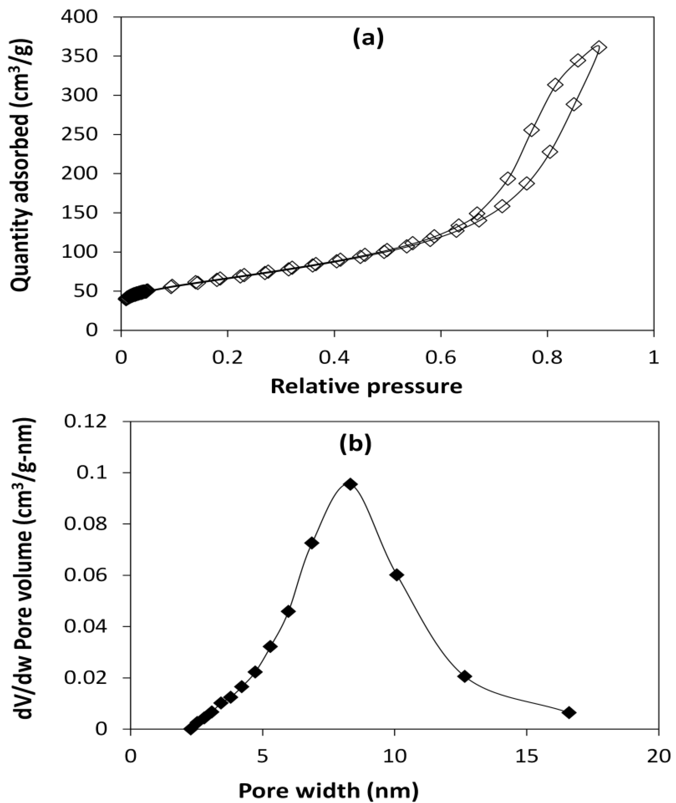
The hydrotreating NiMo/Al2O3 catalyst used has a surface area of 236.4 m2/g (based on BET equation) and pore volume 0.56 cm3/g. The nitrogen adsorption–desorption isotherm and the pore size distribution are shown in Figure 1. The hysteresis loop in the adsorption–desorption isotherms’ curves suggests type IV (Figure 1a), in addition to the pore width range (Figure 1b), signifies mesoporous material. The majority of the pelleted catalyst pore volume contribution is from mesopores with a pore diameter in the range of 6–12 nm, with a much smaller contribution from pores with a diameter less than 5 nm and greater than 12 nm.
The catalyst acid sites happened at 280 °C (0.62 mmol adsorbed (CH3)3CNH2 g−1) and 480 °C (0.12 mmol adsorbed (CH3)3CNH2 g−1), while X-ray diffraction pattern revealed alumina peaks at 46° and 67°, nickel oxide 37.3° and molybdenum oxide 33.6°; these have been reported elsewhere [17].

2.2. API Gravity and Viscosity

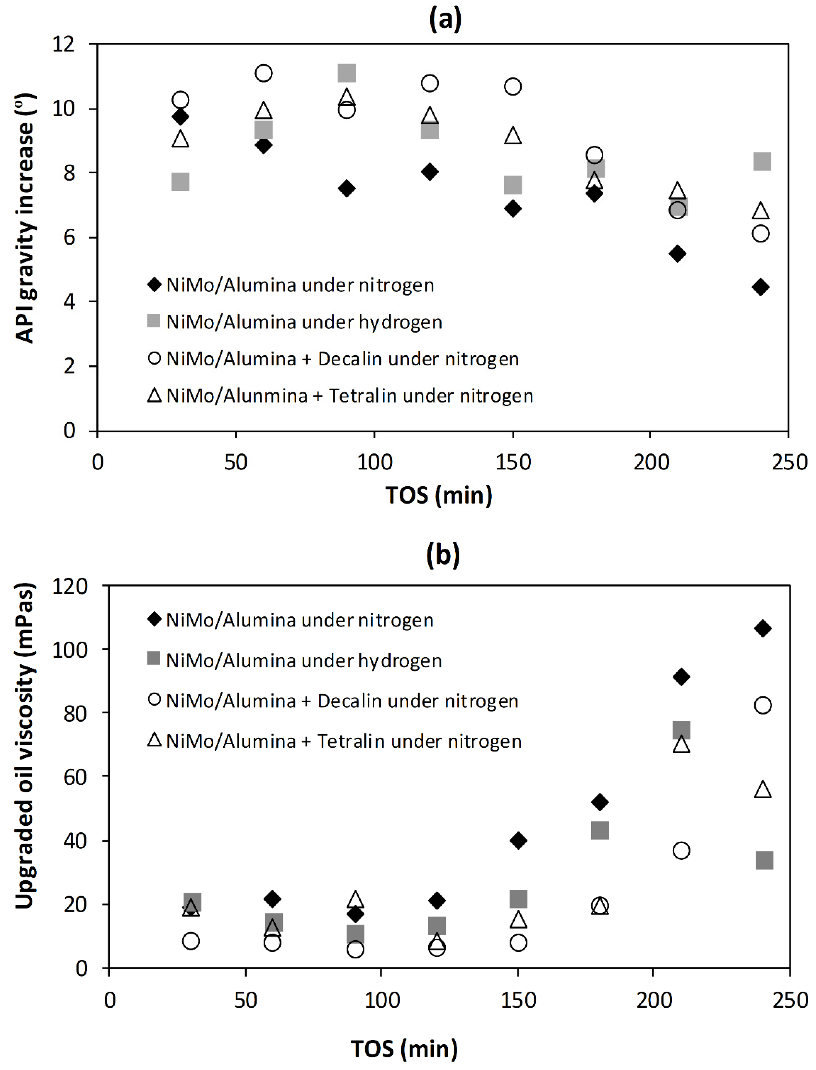
Higher API gravity means the oil contains lighter hydrocarbon components. Figure 2 shows the upgraded oil samples API gravity increase (over 12.8° API for the feed oil) and viscosity as a function of time-on-stream (TOS). The API gravity of the upgraded oil samples under nitrogen gas, nitrogen gas plus tetralin, nitrogen gas plus decalin and hydrogen gas with TOS was relatively stable between 60 and 150 min, before a noticeable decrease could be observed. However, catalyst start-up effect due to wetting and diffusion can be observed in the first data point in Figure 2a.
By taking average levels of upgrading from the different environments reported in Figure 2a, it can be observed that the addition of tetralin and decalin further increase the API gravity points by 1.5° and 2°, respectively, over that achieved under nitrogen gas alone. The addition of hydrogen gas increased the API gravity of the upgraded oil by 8.7° points, representing about 1.4° points above that achieved with nitrogen gas environment. This is consistent with previous observations reported in the literature [9,10,11,12]. The respective viscosities of the upgraded oil samples (Figure 2b) for the different environments are mirror trend to their corresponding API gravity (Figure 2a). The viscosity of produced oil determines its production rate and ease of pipeline transportation. Since an approximately equal amount of oil is collected in the same time interval, the average viscosity is estimated as the sum of viscosities for each experiment divided by eight. Based on Figure 2b, the average viscosities of the oils are as follows: 46 mPas (N2 gas only), 27 mPa.s (tetralin plus N2), 22 mPas (decalin plus N2) and 29 mPas (H2 gas only). These represent several orders of magnitude in viscosity reduction relative to the THAI feed oil (863 mPas). In summary, the increase in API gravity, as well as viscosity reduction, can be summarized as follows: decalin > hydrogen gas >= tetralin > nitrogen gas. This decrease in the API gravity points and the increase in viscosity with TOS (Figure 2) can be associated with the plugging of catalyst pores and fouling of active sites by initial coke deposition [11,25,26].
The observed further improvement in upgraded oil properties in the presence of H-donor solvents, such as tetralin and decalin, over nitrogen gas environment alone indicate their contributing effect. The reason being the shift in composition of the upgraded oil towards the lower molecular weight hydrocarbons as a result of free radicals’ hydrogenation by the liberated hydrogen from the solvents stabilizing intermediate species during upgrading reactions. However, with hydrogen gas, its solubility under the prevailing pressure and reaction condition could have limited its participation, as well as the transport barrier from the gas phase into the liquid phase during upgrading [27]. This is not the case with the miscible H-donor solvents, where the hydrogen liberation happens at the catalyst surface simultaneously with the hydrocarbon cracking in the reaction medium. Consequently, under nitrogen gas atmosphere alone, free radical recombination and aromatic hydrocarbon polymerization to form secondary macromolecular weight hydrocarbons tend to occur, leading to the moderate rise in API gravity observed in Figure 2a.
The upgrading performance for conventional heating method (i.e., exterior-to-interior via a furnace) has been reported elsewhere [10,11,26], for the same THAI heavy oil under a similar experimental condition. When comparing upgrading performance for the two heating methods, it was found that, with conventional heating, the API gravity of the upgraded oil samples increased in the range 2.2–7.3°, while the viscosity decreased to 121 mPas on average relative to the feedstock under nitrogen gas reaction environment [11,26]. In this study, under nitrogen gas atmosphere with induction heating (i.e., interior-to-exterior), the API gravity of the upgraded oil samples increased in ranges from 4.5 to 9.7°, and viscosity about 45 mPas, representing about 2.4° API gravity points above that achieved by conventional heating method. The temperature of the catalytic bed during tetralin dehydrogenation reaction for both conventional and induction heated catalytic bed was reported by Hart et al. [17]. In this earlier study, it was observed that the surface of the catalyst during reaction was hotter with induction heating with steel balls than with conventional heating with a furnace at 300 °C experimental temperature [17]. This suggests that induction heating offers some thermal advantage over conventional heating method. The plausible reason is the rapid manner in which induction heating with steel balls heat up the catalyst and thermally respond to changes in conditions during the upgrading reaction. In contrast, with the conventional heating method via a furnace, the heat transfer rate, as well as the thermal response to changes during reaction, is slow. Additionally, the hot surface of the steel balls induces thermal cracking effect during the upgrading with induction heated catalytic bed, contributing to the improved upgrading observed over the conventional heating method. The additional increase in API gravity points with induction heated catalytic bed over conventional heated method can increase the value of the produced upgraded oil by $2–$10 per barrel [13]. Moreover, it has been proven in our earlier paper [17] that, at the reaction temperature, more hydrogen is liberated from H-donor solvents such as tetralin when the catalytic bed is inductively heated with steel balls than conventional heating via furnace. This synergistic effect of induction heating and H-donor solvents is due to the endothermic nature of the H-donor reaction (mainly dehydrogenation) and the ability of the heating method to swiftly heat up the bed in response to changes in conditions. Hence, more hydrogen will be available for hydrocracking and hydrogenation reactions when the catalytic bed is inductively heated in the presence of a polycyclic organic solvent as H-donor.

2.3. Distillation and Distillate Fractions

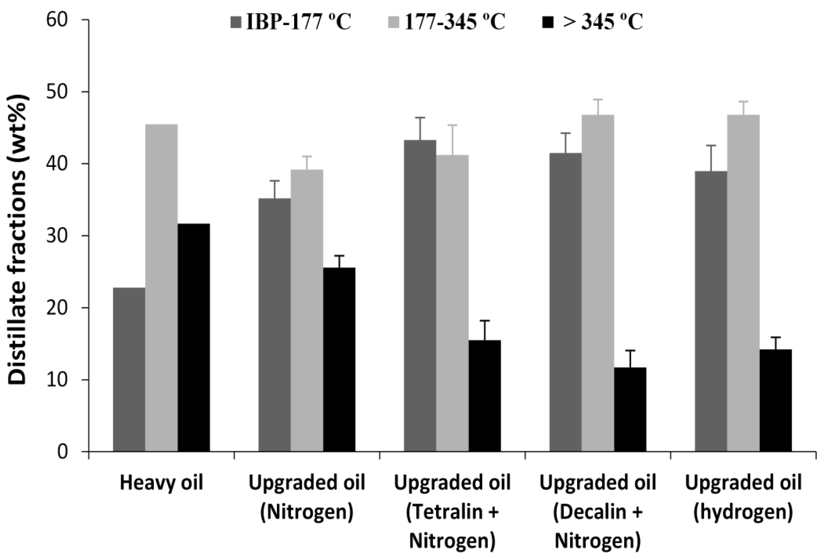
The hydrocarbons present in the oils can be fractionated into the volatiles (i.e., hydrocarbon gases), low molecular weight, the medium molecular weight and the high molecular weight components. The volatiles are non-condensable hydrocarbon vapors liberated between 25 and 37 °C (Initial Boiling Point, IBP), and their amounts are equivalent to the weight loss within the temperature range from the thermogravimetric analyzer (TGA) distillation. In this study, the volatiles were lumped with the naphtha fractions (IBP–177 °C), middle distillate fractions (177–345 °C) and residue greater than 345 °C. This classification provides a more in-depth compositional change that occurred due to upgrading reactions. While the mass percentage loss curve obtained with TGA gives the boiling point distribution of the vaporized components particularly established on the remaining oil in the crucible, in reality, the TBP curve with distillation gives what could be regarded as a condensation curve [28]. It has been reported that the data obtained with TGA present a good correlation factor of 95% at 5% and 10% amount distilled from SimDist ASTM method D2892 [29,30]. The plot of the different distillate fractions is presented in Figure 3.
The same amount of distillate fractions was obtained at lower temperatures for the upgraded oil samples under nitrogen gas only, tetralin, decalin and hydrogen gas only than the original THAI oil. For instance, 50 wt.% distilled fractions occurred at 288 °C (THAI oil), 227 °C (N2 gas only), 191 °C (hydrogen gas), 198 °C (decalin) and 208 °C (tetralin). The drop in temperature relative to 288 °C for the original THAI oil indicates that the upgraded oils contain lower boiling hydrocarbons, as can be observed in Figure 3. The confirmation is mostly evident in the compositional changes in the naphtha, middle distillates and residue fractions, and as a consequence, the observed increase in the API gravity and decrease in the viscosity of the upgraded oil can be noticed in Figure 2. A further decrease in temperature to the lower boiling ranges can be observed when the upgrading reaction was performed under sufficient hydrogen environment, such as with hydrogen gas and decalin, favoring mainly middle distillate production. The significant changes in the upgraded oils are mostly in the naphtha and residue fractions. While the naphtha fractions increased, the residue fractions decreased after upgrading reaction relative the THAI feed oil. This implies high molecular weight components were cracked into volatiles, low and middle molecular weight hydrocarbons, resulting in decreased residue fraction. However, this does not exclude the cracking undergone by the low and middle molecular weight hydrocarbons in the THAI feed oil during the catalytic upgrading reaction.

2.4. Hydrogen Donor Routes

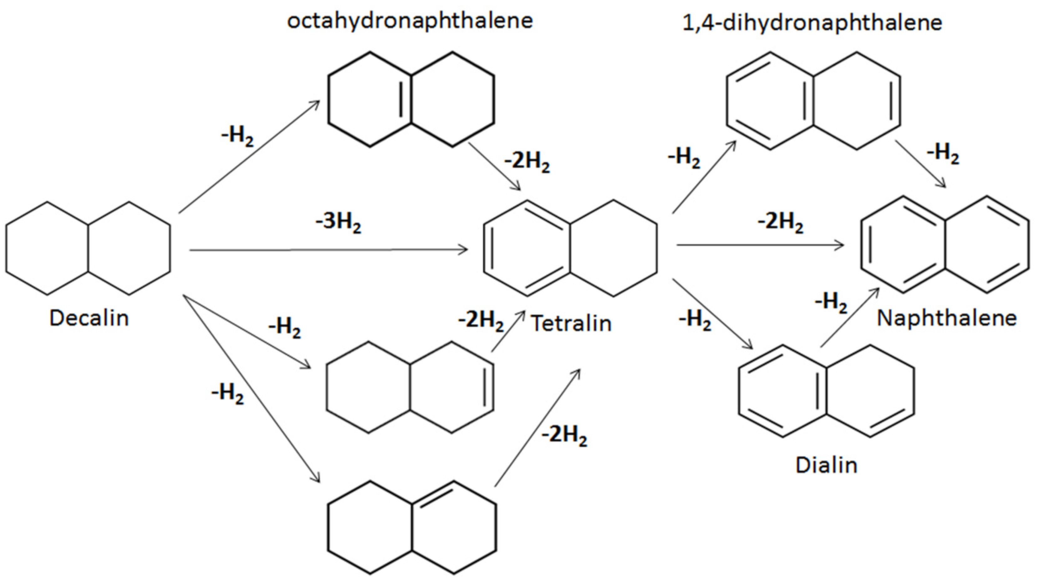
In the presence of catalyst, the main mechanism of hydrogen donation by polycyclic compounds, such as decalin and tetralin, is dehydrogenation [17]. This could occur in two or more consecutive steps, and the reaction routes could be figured out as shown in Scheme 1. Possibly, the released hydrogens from some portion of the polycyclic compounds due to dehydrogenation could also activate ring opening and plausibly cracking into aliphatic hydrocarbons (i.e., RH). This possibility was observed in the dehydrogenation of tetralin reported by Hart et al. [17]. In the light of naphthenic ring opening, hydrogen could be abstracted from the aliphatic hydrocarbons according to Equations (1)–(3). This liberated hydrogen from the H-donor solvents can potentially support and promote in situ hydrogenation and hydrocracking reactions.
2RHsaturated → 2Runsaturated + H2
RH → R + H
RH + H → R + H2

2.5. Coke Formation

Figure 4 shows the mass percentage of weight loss vs. temperature (i.e., thermogravimetric, TG) due to the burn-off of deposited carbonaceous material on the catalyst. The burn-off material from 530 °C can be regarded as hard coke [8,9,10,11,26]. Upgraded oil asphaltene content, spent catalyst coke and burn-off temperature are presented in Table 1. Coke deposited on the catalyst after upgrading reaction is as follows: 21.7% (N2 gas only), 17.3% (tetralin), 13.4% (decalin) and 14.2% (H2 gas only).
Thermodynamically, the liberation of hydrogen from polycyclic organic compounds such as tetralin and decalin is favored at high temperatures, such as 425 °C [17,31]. In the case of tetralin, the complete dehydrogenation of a mole produces naphthalene and only two moles of hydrogen; hence, the reaction medium could have experienced limited hydrogen supply to adequately quench radical fragments of macromolecular weight hydrocarbons [32,33]. This could be the possible reason for the marginally lower coke formation (4.4% decrease in formed coke) with the addition of tetralin solvent, compared with nitrogen gas environment alone. Unlike under nitrogen gas reaction medium, where upgrading reaction is mostly through carbon rejection due to thermal upgrading occurring on the surface of the hot steel balls and catalytic cracking, with H-donor solvents and hydrogen gas, hydrocracking and hydrogenation occur concurrently. Hence, the presence of hydrogen in the reaction medium, either stored in H-donor solvents or free hydrogen gas, deters the chemistry of coke formation. Moreover, it can be observed that the formed coke under limited hydrogen environment is more condensed and harder than that formed under a hydrogen-rich medium such as decalin and hydrogen gas. This is revealed from the coke burn-off temperatures shown in Table 1, which decreased with the addition of H-donor solvents or hydrogen gas.
It can be observed that higher coke formation corresponds to greater asphaltene content in the upgraded oil (Table 1). This is in agreement with the magnitude of the residue fraction (>345 °C) upon distillation of the respective upgraded oil samples, as it is well-known that the asphaltene content is the major component of this fraction (Figure 3). The reason is that, as the original asphaltenes in the heavy oil undergo fragmentation, the H-donor solvent keeps them solubilized while the transfer of hydrogen from the solvent helps to form secondary but lower molecular weight asphaltenes. However, when the catalytic upgrading is carried out under nitrogen gas only, some of the asphaltenes readily precipitate and deposit on the catalyst, particularly once their aliphatic branch chains disintegrate into asphaltenic and aliphatic radicals. Under a limited hydrogen atmosphere, the asphaltenic radicals can polymerize and condense into macromolecular weight species, and continuing abstraction of hydrogen and alkyl radicals causes coke to form. The polymerization reaction is retracted in a rich hydrogen environment, which is the case of H-donors and hydrogen gas experiments; hence, the system is less prone to coke formation. The extent of coke formation reinforced the notion that, under a nitrogen gas medium, catalytic upgrading proceeds via carbon-rejection and dehydrogenation, while in the presence of hydrogen, upgrading is through hydrocracking and hydrogenation reactions, with the latter resulting in less coke formation and catalyst deactivation.
With the conventional heating method under a nitrogen gas reaction medium, it was reported in earlier papers that the deposited coke on the catalyst was about 27% [10,11,26]. In contrast to this study, with induction heating via steel balls, approximately 22% coke was observed on the catalyst. This represents 5% lower coke formation with induction heating. This is in agreement with the observation of Abu-Laban et al. [18], for a comparative study of deoxygenation of pyrolysis oil using induction heating of pelleted Pt/Al2O3 catalyst mixed with steel balls and conventional heating with heating cable. Unlike conventional heating in which heat flow into the catalyst from the surrounding fluid, for induction heating, the rapid heat up of catalyst and surrounding fluids by the steel balls causes heat to flow outwardly from the catalyst surface, promoting desorption of molecules, and thus deterring the polymerization and condensation reactions responsible for coke formation [18,31]. The reason for this is that the surface of the catalyst is hotter than the surrounding fluid [17].
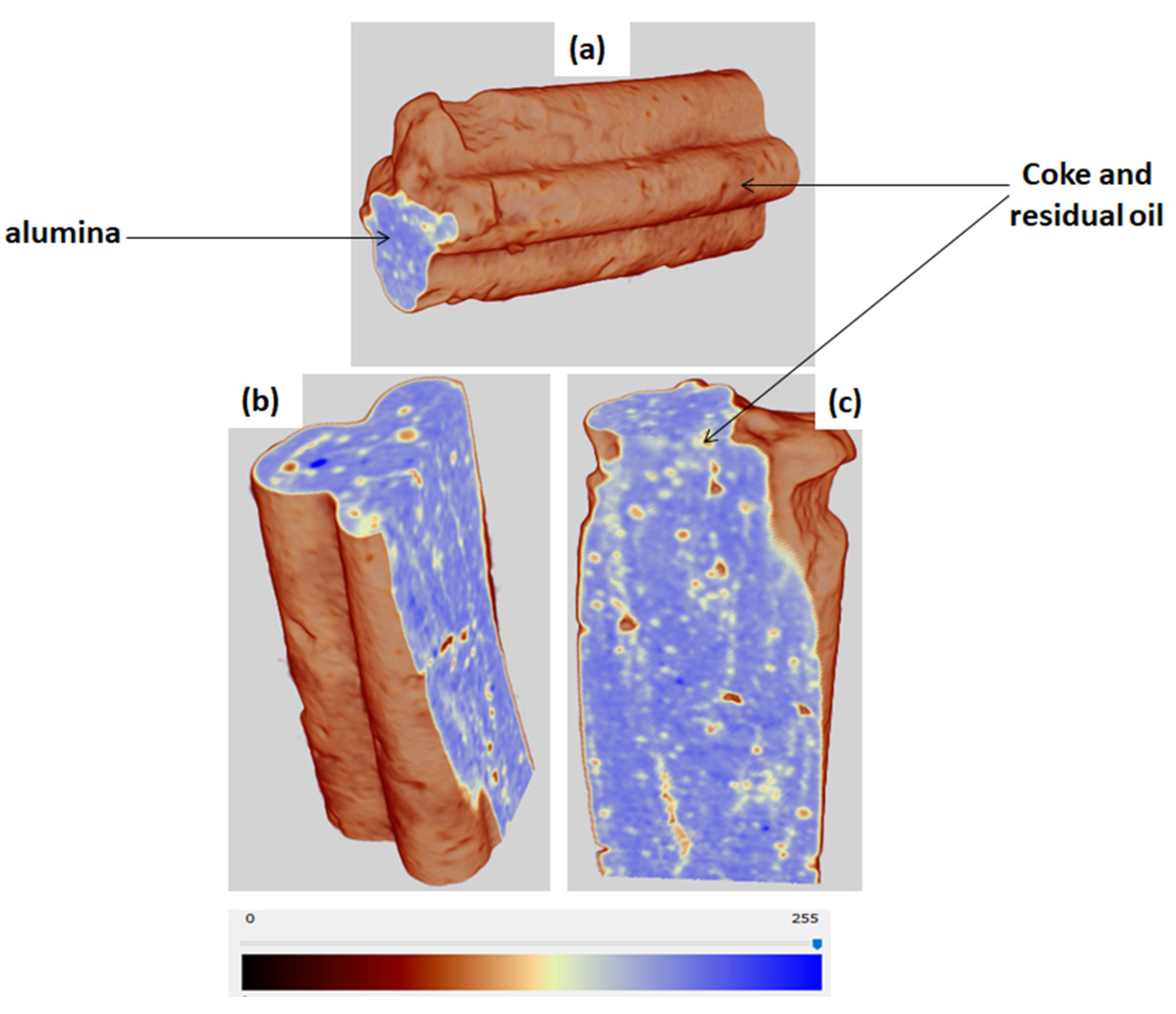
X-ray nano-CT imaging was used to examine coke deposition within the microstructure of the pelleted spent catalyst in full 3D. This imaging technique was utilized by Lomas et al. [34] to study metallurgical coke fracture, and Zhang et al. [35] to examine coke deposition resulting from catalytic heavy oil devolatilization. The interior reconstruction of the catalyst structure can be obtained, providing details of the microstructural changes that have taken place after reaction. Figure 5 shows the 2D slice images of the spent catalyst composed of voxels (volume elements). The reconstructed volumetric representation (3D image) of the catalyst consisting of stacked images of 2D slices is shown in Figure 6.
It is obvious that the pelleted catalyst was greatly encapsulated by coke and residual oil (Figure 6). The different material features and phases are manifested through the variation in grayscale intensities in the images of Figure 5 and Figure 6, due to disparity in X-ray absorption which is a function of X-ray energy, the density differences between the deposited coke and the alumina support, and the heterogeneity of the spent catalyst. The distinct topographies in the image help to identify the coke and the alumina components of the spent catalyst. Hence, in the 2D images (Figure 5), the green color represents coke and residual oil deposits, while the brown color segments of Figure 6 represent coke deposit and residual oil within the pore spaces of the catalyst, and the blue area is solid alumina in both.
In Figure 5 and Figure 6, the coke deposits increase near the external surface of the catalyst pellet and are scanty within the interior. This indicates that the pelleted catalyst experienced coke formation more at and near its external surface, signifying pore-mouth blockage and underutilization of the interior (Figure 6b,c). This is supported by the TGA result presented in Figure 4 in which coke burn-off was observed from the spent catalyst samples. Unlike TGA, X-ray nano-CT provided the location of the coke deposits within the catalyst pellet. The pore plugging can be attributed to the size of the macromolecular weight species, such as resin and asphaltene, present in the heavy oil and the pore size distribution of the catalyst. The X-ray nano-CT image also shows that, while the interior porous structure of the pelleted catalyst is slightly affected by the coking, the exterior is significantly modified by coke formation. This is in agreement with the coke deposition from heavy oil devolatilization by using Fluid Catalytic Cracking (FCC) catalyst reported by Zhang et al. [35]. The structural changes in the pellets near the exteriors due to coke deposition leading to pore-mouth blockage is behind the rapid deactivation reflected in the API gravity with TOS shown in Figure 2. The center of the pelleted catalyst is still porous, suggesting that the heavy oil molecules have limited access to the interior surface and internal channels of the catalyst. The macromolecular-weight species, such as resin and asphaltene, would have experienced diffusion limitation in the pores and channels whose diameter ranges from 3 to 16 nm (Figure 1b). Contrary to nitrogen adsorption–desorption isotherm, which showed that the catalyst pellets loss 96% of porosity and surface area to coke deposition in the earlier papers [9,11,26], the X-ray nano-CT reveals poor utilization of the pelleted catalyst interior, due to the coke deposit majorly at the external surface of the catalyst. This suggests that most of the upgrading is due to catalytic cracking largely at the external surface of catalyst, explaining the pore-mouth plugging leading to deactivation. This challenge can be solved through nanoparticles application, which exposes more active sites and possesses short diffusion length unlike their pelleted counterpart. Hence, the risk of pore-mouth blockage and macromolecular-weight species diffusion limitation will be greatly minimized.
In our earlier paper [11], we demonstrated that oxidative-regeneration of the coked spent catalyst at 600 °C for 4 h, could recover up to 50% of the catalyst surface area and 60% pore volume after catalytic upgrading of the same THAI feed oil and with the same experimental conditions. Consequently, the level of catalytic upgrading achieved in terms of API gravity increase and viscosity reduction by the regenerated catalyst were comparable with those achieved with the fresh counterpart [11]. This suggests that coke formation and deposition resulting in active site coverage and pore-mouth blockage are the major cause of catalyst deactivation during catalytic upgrading of heavy oils with catalyst pellets.

3. Materials and Methods

3.1. Materials

Commercial hydrotreating (HDT) catalyst NiMo/Al2O3 with dimensions (quadrilobed-shaped: diameter (a,b) 1.4 × 1.2 mm and length 4.6 ± 2.2 mm) was used in this work. The catalyst comprises approximately 7% nickel promoter and 21% molybdenum active metal in their oxide form. Detailed physicochemical properties and characteristics of the HDT catalyst have been reported elsewhere [17]. Touchstone Exploration Inc., Canada, supplied the heavy oil used in this work, which is a mixture of oils produced from eight different reservoirs, using THAI process at Kerrobert field, Saskatchewan, Canada. Table 2 displays the heavy oil properties.
The solvents and gases used include tetralin, 99.5% purity (1,2,3,4-tetahydronaphthalene, CAS Number: 119-64-2, Sigma Aldrich, Gillingham, UK); decalin, 99.6% purity (decahydronaphthalene, CAS Number: 91-17-8, Sigma Aldrich, Gillingham, UK); nitrogen gas (BOC Group, Birmingham, UK); and hydrogen gas, 99.95% purity (BOC Group, Birmingham, UK). Tetralin and decalin solvents were chosen to evaluate their hydrogen-donor capabilities in comparison to catalytic upgrading achieved by using a hydrogen gas environment, whilst nitrogen gas was used to simulate catalytic upgrading via carbon-rejection and dehydrogenation in addition to being cheaper than argon and helium.

3.2. Experimental Setup

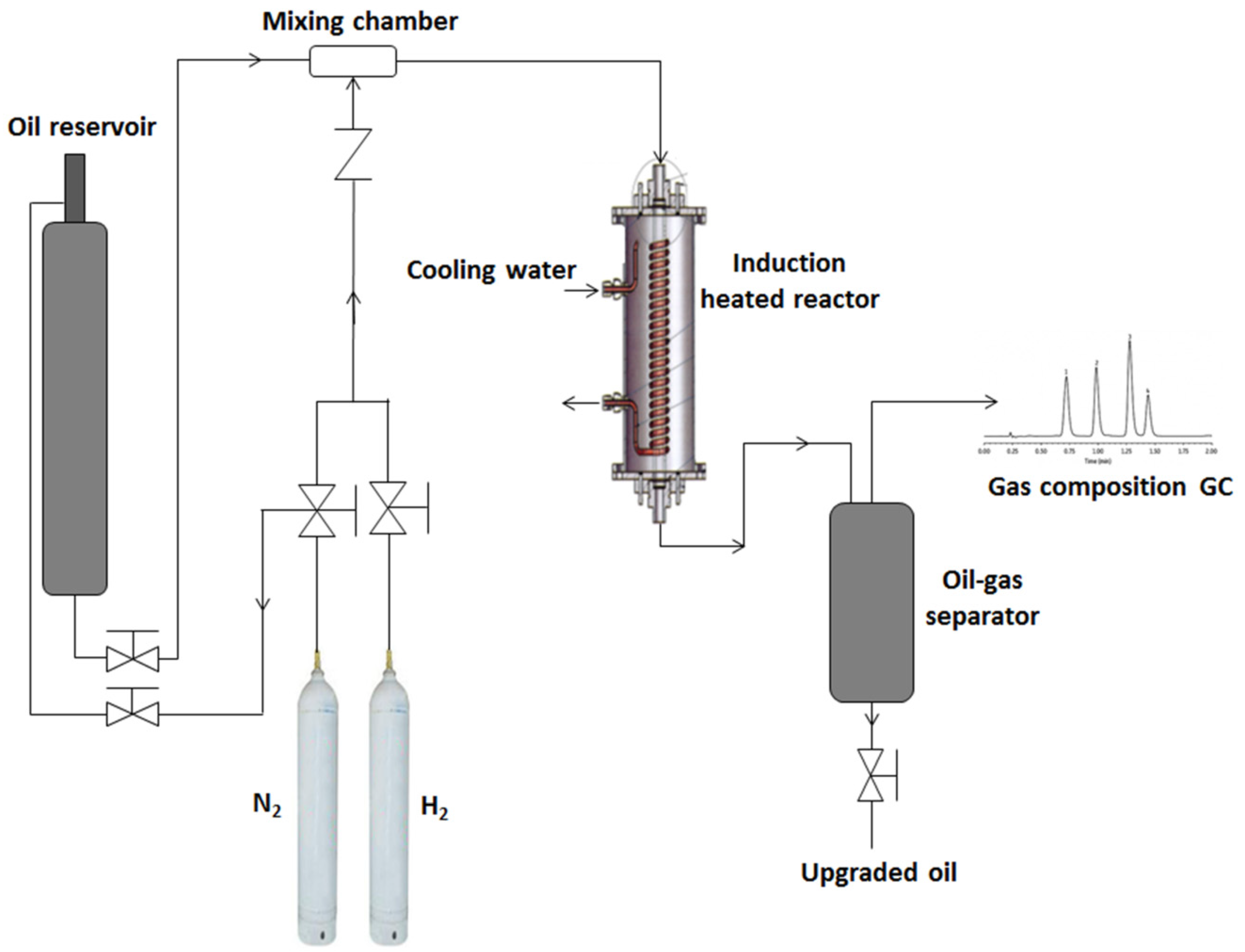
The induction heating unit was built by Inductelec, UK, while the catalytic reactor system was assembled by C-Tech Innovation, UK, and commissioned at the School of Chemical Engineering, University of Birmingham, UK. Figure 7 shows the schematics of the induction heating catalytic reactor and the experimental setup. The induction coil used was a sixty-loop-coated copper coil with an inner diameter 44 mm and loop length of 230 mm. The area covered by the copper coils represents the actual reaction zone where the heat is generated, and the catalyst and steel balls (3 mm) were packed within this zone inside the quartz glass tube (20 mm i.d., 40 mm o.d. × 440 mm). The packed bed within the quartz glass tube represents the thickness of catalyst layer wrapped around the horizontal production well of the THAI process. The temperature of the catalytic bed was measured with installed thermocouple (k-type) from the bottom of the reactor, which was validated with a secondary thermocouple inserted into the packed bed; immediately the induction heating was turned off once 425 °C was reached, eliminating the interference of magnetic field. A detailed procedure has been reported elsewhere [17].
First, a composite catalyst comprising 40% (v/v) iron filings to alumina binder ratio was designed, and also 3 mm wire gauze constructed to potentially convert the magnetic field into heat. These two designs were tested, and error message was displayed on the Inductelec liquid crystal display (LCD), indicating insufficient susceptibility effect. This can be attributed to the thickness of the non-conducting quartz glass tube (10 mm) impeding their interaction with the magnetic field generated inside the tube, due to the wrapped induction coil (Figure 7). Hence, a mixed bed system of catalyst and steel balls (3 mm) was investigated. The catalyst-to-steel-balls ratio used was 66% (v/v), of which 28 g was catalyst and the steel balls converted the magnetic field into heat, thereby heating the entire packed bed (NiMo/Al2O3 and steel balls). The top and bottom of the packed bed was occupied by glass beads (5 mm), to eliminate interaction with magnetic field and ensure feed oil distribution and adequate catalyst bed wetting. The reactor was operated in the downward flow mode in order to simulate the gravity drainage of the mobilized hot oil ahead of the combustion front in the THAI process, as well as complete catalyst wetting. The THAI feed oil was fed through lines heated to 290 °C by trace heating rope; this simulates typical temperature of the mobilized hot ahead of the combustion front in the THAI process prior to passing over the catalyst layer in the CAPRI process, as well as lowers the heating load in the catalytic reactor. The THAI oil reservoir was pressurized by nitrogen to 25 barg, to push the oil through the line, as shown in Figure 7. The operating conditions of temperature 425 °C (the optimum reported by Shah et al. [8]) and pressure 15 barg were established at steady state. Then the oil-flow metering valve was manually opened to initiate oil flow from the THAI oil reservoir through the trace cable heated line (290 °C) into the induction-heated catalytic reactor, at an adjusted flowrate of 1 ± 0.3 mL/min. The reaction medium was either nitrogen or hydrogen gas, depending on the experiment at 400 mL/min, as shown in Figure 1. The height of the mixed bed of catalyst and steel balls was 230 mm, while the bed porosity was 0.38. The pressure inside the reactor was controlled by back pressure regulator (Swagelok, Manchester, UK), through the regulation of gas holdup inside the reactor. The ratio of H-donor solvent to oil used was 0.045 (g/g), which is within the range of the optimum reported by Hart et al. [22]. The addition of the H-donor solvent caused negligible impact on the API gravity of the THAI feed oil, while the resultant effect on viscosity due to thinning was less than a 10% decrease. The upgraded oil and gas flowed into the oil–gas separator, where the upgraded oil was collected from the bottom and the flashed-off gas was either sent to gas chromatograph (GC) configured as a refinery gas analyzer (RGA) or vented. The upgraded oil came out foamy, signifying that the oil and gas were well mixed in the mixing chamber and the reactor. Before the start of each experiment, the 28 g NiMo/Al2O3 catalyst in the mixed bed was reduced in situ, using hydrogen gas flow of 50 mL/min and pressure of 5 bar at 300 °C for 30 min. This procedure converts the nickel and molybdenum components of the catalyst from their oxide state to active metals. Moreover, since the sulfur content of the THAI feed oil is high (Table 2), it is believed that in situ sulfidation also occurred during the catalytic upgrading, converting the nickel and molybdenum into their respective sulfide state [9,11,26].

3.3. Analytical Techniques

A Micromeritics Analytical Instrument ASAP® 2010 was used to perform nitrogen adsorption–desorption cycles, and catalyst surface area was determined by fitting the Brunauer–Emmett–Teller (BET) model to the data, while the Barrett–Joyner–Halenda (BJH) equation was used to determine the pore size distribution. The number and strength of the acid sites of the NiMo/Al2O3 catalyst used was determined by temperature programmed desorption (TPD), using Micromeritics AutoChem II 2920 analyzer (Micromeritics Instrument Corporation, Norcross, GA, USA), tert-butylamine (CH3)3CNH2 g−1) and 0.2 g of catalyst. A ramp temperature from 25 to 500 °C at 10 °C/min for 60 min under argon gas flow 50 mL/min was used, and it was desorbed with helium gas flow 50 mL/min. A portable density meter Anton Parr DMA 35 (Anton Paar GmbH, Graz, Austria) was used to measure the API gravity of the oil samples. The viscosity of the oil samples was measured with the rheometer Bohlin CVO 50NF (Malvern Instruments Ltd., Worcester, UK) at 20 °C, using parallel plate geometry with 100 μm gap and 100 s−1 constant shear rate. The asphaltene content of the oil samples was precipitated by mixing 1 g of oil to 40 mL n-heptane, and carried out in accordance to American Society for Testing and Material (ASTM) method D3279.
Diaz and Yarranton [36] reported that calibrated simulated distillation (SimDist) with paraffinic standards, and conventional reference oil is not suitable for heavy oil and bitumen characterization. Hence, the true boiling point (TBP) curves of the oil samples was obtained by using a Thermogravimetric Analyzer, TGA (TG 209 F1 Iris® instrument, NETZSCH-Geratebau GmbH, Selb, Germany), with the temperature ramped from 25 to 345 °C, at a heating rate of 10 °C/min, and an isothermal 345 °C for 5 min, to ensure complete vaporization of the middle distillate fractions under nitrogen flowrate of 40 mL/min. The measured weight loss due to evaporation of light and middle distillate fractions as the sample is heated in an inert atmosphere (N2), gives similar data to distillation curve obtained using ASTM method D86 [28,37], and also with SimDist using ASTM method D2892 [28]. However, beyond 350 °C, complex cracking reactions begins to occur [38]. Hence, to avoid thermal cracking reactions, the TGA was conducted only to the limit of boiling temperature of the middle distillate fractions (345 °C). Nonetheless, to ensure accuracy, the sample size was very small (8 mg), in order to allow a quick exit of the vaporized portion, as well as ensure weight loss matches component boiling point distribution.
The coke deposited on the catalyst after upgrading experiments was determined by using TGA programmed as follows: a ramped temperature from 25 to 900 °C, at a heating rate of 10 °C/min, and an isothermal temperature of 900 °C for 10 min, under air flowrate of 50 mL/min. The microstructure and density of the spent catalyst pellet were examined using X-ray Computed Nanotomography, X-ray nano-CT (Bruker SkyScan 2211, Billerica, MA, USA).The scan was carried out without any special sample preparation, using microfocus mode, voltage 85 kV, emission current 210 μA, exposure time 130 ms, image pixel size 7 μm and rotation step 0.2°.

4. Conclusions

The effects of tetralin and decalin as H-donor solvents in an inductively heated catalytic upgrading of heavy oil were investigated at a temperature 425 °C, pressure 15 bar, catalyst/steel balls 66% (v/v), H-donor/oil 0.045 (g/g) and LHSV 0.75 h−1. The results were evaluated with those obtained under nitrogen gas and hydrogen gas environments, and also against previously reported results for the same THAI oil and experimental conditions with conventional heating under nitrogen gas reaction medium alone. It was found that under nitrogen gas medium alone, inductively heated catalytic bed produced upgraded oils with API gravity increase with TOS in the range of 4.5–9.7°, while conventional heating achieved 2.2–7.3° above 12.8° for the THAI oil. Likewise, viscosity was 45 mPas (induction heating) against 121 mPas (conventional heating) relative to 863 mPas for the THAI heavy oil. The addition of hydrogen gas achieved a 1.4° point increase above 7.3° (nitrogen gas alone), while the incorporation H-donor solvents further increased the API gravity by 1.5° (tetralin) and 2° (decalin), respectively. The formation of coke was suppressed under hydrogen gas and H-donor solvents in the following order: nitrogen gas (22%) < tetralin (17%) < hydrogen gas (14%) < decalin (13.4%). It is clear that decalin suppressed coke formation slightly better than hydrogen gas, and this difference can be attributed to hydrogen gas solubility in the oil under the prevailing pressure and temperature, and the ability of the decalin to solubilized the asphaltene while the liberated hydrogen halt free radicals polymerization to form stable and lower molecular weight hydrocarbon molecules. Additionally, the endothermic nature of the reaction resulting in hydrogen liberation from H-donor solvents, such as tetralin and decalin, and the ability of the induction heating method to heat up the catalytic bed rapidly in response to changes provides a synergistic effect that promotes further hydrocracking and hydrogenation. This reduction of coke formation under a hydrogen-rich environment proves the role of hydrogen in catalyst longevity and quality of produced oil during catalytic upgrading of heavy oil. Conclusively, a pelleted catalyst with micro- and meso-pores suffers pore-mouth plugging, leading to rapid loss of catalytic activity, which is reflected in API gravity decrease within 150 min TOS, suggesting macro-porous catalyst to accommodate species such as resins and asphaltenes, or dispersed nano-sized catalyst to avoid diffusion limitation, pore-mouth blockage and expose the macromolecular weight species to the active sites during catalytic upgrading of heavy oil.
Author Contributions

Conceptualization, J.W. and A.H.; methodology, J.W., M.A. and A.H.; investigation, A.H.; resources, J.W.; writing—original draft preparation, A.H.; writing—review and editing, J.W., M.A., J.P.R. and S.P.R.; supervision, J.W. and S.P.R.; project administration, S.P.R., J.W. and J.P.R.; funding acquisition, S.P.R., J.W. and J.P.R. All authors have read and agreed to the published version of the manuscript.

Funding

This research was funded by the Engineering and Physical Science Research Council (EPSRC), UK, grant number EP/N032985/1.

Acknowledgments

The authors acknowledge the technical support of John Wedderburn, School of Metallurgy and Materials, University of Birmingham, UK, on the nitrogen adsorption–desorption isotherm of the catalyst used in this study. We are grateful to David Boylin and Andrew Tanner for their technical assistance with the maintenance of the experimental rig.

Conflicts of Interest

The authors declare no conflict of interest.

References

  1. Hart, A.; Wood, J. In Situ catalytic upgrading of heavy crude with CAPRI: Influence of hydrogen on catalyst pore plugging and deactivation due to coke. Energies 2018, 11, 636. [Google Scholar] [CrossRef] [Green Version]
  2. Demirbas, A.; Alidrisi, H.; Balubaid, M.A. API gravity, sulfur content, and desulfurization of crude oil. Pet. Sci. Technol. 2014, 33, 93–101. [Google Scholar] [CrossRef]
  3. Greaves, M.; Xia, T.; Turta, A.; Ayasse, C. Recent laboratory results of THAI and its comparison with other IOR processes. In Proceedings of the SPE/DOE Improved Oil Recovery Symposium, Tulsa, Oklahoma, 3–5 April 2000. [Google Scholar]
  4. Wei, W.; Wang, J.; Afshordi, S.; Gates, I.D. Detailed analysis of Toe-to-Heel Air Injection for heavy oil production. J. Pet. Sci. Eng. 2020, 186, 106704. [Google Scholar] [CrossRef]
  5. Greaves, M.; Dong, L.L.; Rigby, S.P. Validation of Toe-to-Heel air-injection bitumen recovery using 3D combustion-cell results. SPE Reserv. Eval. Eng. 2012, 15, 72–85. [Google Scholar] [CrossRef]
  6. Xia, T.; Greaves, M. 3-D physical model studies of downhole catalytic upgrading of wolf lake heavy oil using THAI. In Proceedings of the Canadian International Petroleum Conference, Calgary, AB, Canada, 12–14 June 2001. [Google Scholar]
  7. Xia, T.; Greaves, M.; Werfilli, W.; Rathbone, R. Downhole conversion of lloydminster heavy oil using THAI-CAPRI process. In Proceedings of the SPE International Thermal Operations and Heavy Oil Symposium and International Horizontal Well Technology Conference, Calgary, AB, Canada, 4–7 November 2002. [Google Scholar]
  8. Shah, A.; Fishwick, R.P.; Leeke, G.A.; Wood, J.; Rigby, S.P.; Greaves, M. Experimental optimisation of catalytic process in situ for heavy-oil and bitumen upgrading. J. Can. Petrol. Technol. 2011, 50, 33–47. [Google Scholar] [CrossRef]
  9. Hart, A.; Shah, A.; Leeke, G.; Greaves, M.; Wood, J. Optimization of the CAPRI process for heavy oil upgrading: Effect of hydrogen and guard bed. Ind. Eng. Chem. Res. 2013, 52, 15394–15406. [Google Scholar] [CrossRef]
  10. Hart, A.; Leeke, G.; Greaves, M.; Wood, J. Downhole heavy crude oil upgrading using CAPRI: Effect of steam upon upgrading and coke formation. Energy Fuels 2014, 28, 1811–1819. [Google Scholar] [CrossRef]
  11. Hart, A.; Leeke, G.; Greaves, M.; Wood, J. Down-hole heavy crude oil upgrading by CAPRI: Effect of hydrogen and methane gases upon upgrading and coke formation. Fuel 2014, 119, 226–235. [Google Scholar] [CrossRef] [Green Version]
  12. Hart, A.; Wood, J.; Greaves, M. Laboratory investigation of CAPRI catalytic THAI-add-on process for heavy oil production and in situ upgrading. J. Anal. Appl. Pyrolysis 2017, 128, 18–26. [Google Scholar] [CrossRef]
  13. Ayasse, C.; Greaves, M.; Turta, A. Oilfield In Situ Hydrocarbon Upgrading Process. US Patent No. 6412557 B1, 2 July 2002. [Google Scholar]
  14. Petrobank Energy and Resources Ltd. Strength in Heavy Oil: Growing THAITM Globally. 2007. Available online: https://www.knotia.ca/kstore/productinfo/fric08/PDFs/Petrobank%20Energy%20and%20Resources%20Ltd.%20AR_2007.pdf (accessed on 29 February 2018).
  15. Ado, M.R.; Greaves, M.; Rigby, S.P. Dynamic simulation of the Toe-to-Heel air injection heavy oil recovery process. Energy Fuels 2017, 31, 1276–1284. [Google Scholar]
  16. Henkel, C.; Muley, P.D.; Abdollahi, K.K.; Marculescu, C.; Boldor, D. Pyrolysis of energy cane bagasse and invasive Chinese tallow tree (Triadica sebifera L.) biomass in an inductively heated reactor. Energy Convers. Manag. 2016, 109, 175–183. [Google Scholar] [CrossRef]
  17. Hart, A.; Adam, M.; Robinson, J.P.; Rigby, S.P.; Wood, J. Inductive heating assisted-catalytic dehydrogenation of tetralin as a hydrogen source for downhole catalytic upgrading of heavy oil. Top. Catal. 2019, 1–13. [Google Scholar] [CrossRef] [Green Version]
  18. Abu-Laban, M.; Muley, P.D.; Hayes, D.; Boldor, D. Ex-situ up-conversion of biomass pyrolysis bio-oil vapors using Pt/Al2O3 nanostructured catalyst synergistically heated with steel balls via induction. Catal. Today 2017, 291, 3–12. [Google Scholar] [CrossRef]
  19. Zadražil, A.; Štěpánek, F. Remote control of reaction rate by radiofrequency heating of composite catalyst pellets. Chem. Eng. Sci. 2015, 134, 721–726. [Google Scholar] [CrossRef]
  20. Varsano, F.; Bellusci, M.; Provini, A.; Petrecca, M. NiCo as catalyst for magnetically induced dry reforming of methane. IOP Conf. Series: Mater. Sci. Eng. 2018, 323, 012005. [Google Scholar] [CrossRef]
  21. Sebastián, D.; Bordejé, E.; Calvillo, L.; Lazaro, M.J.; Moliner, R. Hydrogen storage by decalin dehydrogenation/naphthalene hydrogenation pair over platinum catalysts supported on activated carbon. Int. J. Hydrogen Energy 2008, 33, 1329–1334. [Google Scholar] [CrossRef]
  22. Hart, A.; Lewis, C.; White, T.; Greaves, M.; Wood, J. Effect of cyclohexane as hydrogen-donor in ultradispersed catalytic upgrading of heavy oil. Fuel Process. Technol. 2015, 138, 724–733. [Google Scholar] [CrossRef] [Green Version]
  23. Alemán-Vázquez, L.O.; Cano-Domínguez, J.L.; García-Gutiérrez, J.L. Effect of tetralin, decalin and naphthalene as hydrogen donors in the upgrading of heavy oils. Procedia Eng. 2012, 42, 532–539. [Google Scholar] [CrossRef] [Green Version]
  24. Chen, W.-H.; Chen, C.-Y. Water gas shift reaction for hydrogen production and carbon dioxide capture: A review. Appl. Energy 2020, 258, 114078. [Google Scholar] [CrossRef]
  25. Kim, J.-W.; Longstaff, D.C.; Hanson, F.V. Upgrading of bitumen-derived heavy oils over a commercial HDN catalyst. Fuel 1997, 76, 1143–1150. [Google Scholar] [CrossRef]
  26. Hart, A. Advanced Studies of Catalytic Upgrading of Heavy Oils. Ph.D. Thesis, University of Birmingham, Birmingham, UK, 2014. [Google Scholar]
  27. Mapiour, M.; Sundaramurthy, V.; Dalai, A.K.; Adjaye, J. Effects of hydrogen partial pressure on hydrotreating of heavy gas oil derived from oil-sands bitumen: Experimental and kinetics. Energy Fuels 2010, 24, 772–784. [Google Scholar] [CrossRef]
  28. Rannaveski, R.; Järvik, O.; Oja, V. A new method for determining average boiling points of oils using a thermogravimetric analyser. J. Therm. Anal. Calorim. 2016, 126, 1679–1688. [Google Scholar] [CrossRef]
  29. Ali, M.A.; Siddiqui, M.A.B.; Zaidi, S.M.J. Thermal analysis of crude oils and comparison with SIMDIST and TBP distillation data. J. Therm. Anal. Calorim. 1998, 51, 307–319. [Google Scholar] [CrossRef]
  30. Gonçalves, M.L.A.; da Mota, A.D.; Teixeira, R.F.A.M.; Teixeira, M.A.G. Thermogravimetric investigation on prediction of thermal behaviour of petroleum distillation residues. J. Therm. Anal. Calorim. 2005, 80, 81–86. [Google Scholar] [CrossRef]
  31. Suttisawat, Y.; Sakai, H.; Abe, M.; Rangsunvigit, P.; Horikoshi, S. Microwave effect in the dehydrogenation of tetralin and decalin with a fixed-bed reactor. Int. J. Hydrogen Energy 2012, 37, 3242–3250. [Google Scholar] [CrossRef]
  32. Wang, Y.; Shah, N.; Huggins, F.E.; Huffman, G.P. Hydrogen production by catalytic dehydrogenation of tetralin and decalin over stacked cone carbon nanotube-supported Pt catalysts. Energy Fuels 2006, 20, 2612–2615. [Google Scholar] [CrossRef]
  33. Chen, Z.; Xie, J.; Liu, Q.; Wang, H.; Gao, S.; Shi, L.; Liu, Z. Characterization of direct coal liquefaction catalysts by their sulfidation behavior and tetralin dehydrogenation activity. J. Energy Inst. 2019, 92, 1213–1222. [Google Scholar] [CrossRef]
  34. Lomas, H.; Jenkins, D.R.; Mahoney, M.R.; Pearce, R.; Roest, R.; Steel, K.M.; Mayo, S. Examining mechanisms of metallurgical coke fracture using micro-CT imaging and analysis. Fuel Process. Technol. 2017, 155, 183–190. [Google Scholar] [CrossRef]
  35. Zhang, S.Y.; Lu, X.; Owen, E.R.; Manos, G.; Xu, R.; Wang, R.F.; Maskell, C.W.; Shearing, R.P.; Brett, J.L.D. Fine structural changes of fluid catalytic catalysts and characterization of coke formed resulting from heavy oil devolatilization. Appl Catal B Environ. 2020, 263, 118329. [Google Scholar] [CrossRef]
  36. Diaz, O.C.; Yarranton, H.W. Applicability of simulated distillation for heavy oils. Energy Fuels 2019, 33, 6083–6087. [Google Scholar] [CrossRef]
  37. Li, L.-P.C.F. Simulated distillation of coal tar. Energy Sources 2001, 23, 189–199. [Google Scholar]
  38. Barneto, A.; Carmona, J.A.; Barrón, A. Thermogravimetric monitoring of crude oil and its cuts in an oil refinery. Energy Fuels 2015, 29, 2250–2260. [Google Scholar] [CrossRef]
Figure 1. Catalyst characteristics of (a) nitrogen adsorption–desorption isotherm and (b) the pore size distribution.
Catalysts 10 00393 g001
Figure 2. Upgraded oil with time-on-stream (TOS); (a) American Petroleum Institute (API) gravity increase (respective standard deviation: N2 gas (±0.86°), H2 gas (±0.60°), tetralin (±0.89°) and decalin (±1.2°)) and (b) viscosity (respective standard deviation: N2 gas (±5.7 mPas), H2 gas (±4.8 mPas), tetralin (±2.4 mPas) and decalin (±3.2 mPas)).
Catalysts 10 00393 g002
Figure 3. Feed oil and upgraded oils distillate fractions.
Catalysts 10 00393 g003
Scheme 1. Dehydrogenation routes for hydrogen liberation.
Catalysts 10 00393 sch001
Figure 4. Coke deposited on spent catalyst.
Catalysts 10 00393 g004
Figure 5. X-ray nano-CT 2D slice images of the spent catalyst after catalytic upgrading at a temperature of 425 °C, pressure 15 barg, N2 gas-to-oil flow ratio 400 mL/mL, catalyst-to-steel-balls ratio 66% (v/v), tetralin-to-oil ratio 0.045 (g/g) and 4 h TOS taken at different position.
Catalysts 10 00393 g005
Figure 6. X-ray nano-CT 3D image of the spent NiMo/Al2O3 catalyst after upgrading at a temperature of 425 °C, pressure 15 barg, N2 gas-to-oil flow ratio 400 mL/mL, catalyst-to-steel-balls ratio 66% (v/v), tetralin-to-oil ratio 0.045 (g/g) and 4 h TOS (a) pellet and the cross-section images (b,c).
Catalysts 10 00393 g006
Figure 7. Schematic diagram of the induction heated catalytic reactor setup.
Catalysts 10 00393 g007
Table 1. Upgraded oil asphaltene content, spent catalyst coke and burn-off temperature.
CatalystCoke (%)Complete Burn-Off Temperature
(°C)
Asphaltene
(wt.%)
NiMo/Al2O3 (N2)21.76328.8
NiMo/Al2O3 (Decalin + N2)13.45856.2
NiMo/Al2O3 (Tetralin + N2)17.36287.4
NiMo/Al2O3 (H2)14.25916.4
Table 2. Properties of Toe-to-Heel Air Injection (THAI) heavy oil.
ParameterValue
API gravity (°)12.8
Viscosity at 20 °C (mPas)863
Asphaltene (wt.%)14.6
Sulfur (wt.%)3.52
Ni + V (ppm mass)150
C (wt.%)84.7
H (wt.%)10.8
H/C0.13