Article

Influence of TiO2 Morphology and Crystallinity on Visible-Light Photocatalytic Activity of TiO2-Bi2O3 Composite in AOPs

Laboratory for Environmental Sciences and Engineering, Department of Inorganic Chemistry and Technology, National Institute of Chemistry, Hajdrihova 19, SI-1001 Ljubljana, Slovenia
*
Author to whom correspondence should be addressed.
Catalysts 2020, 10(4), 395; https://doi.org/10.3390/catal10040395
Submission received: 12 March 2020 / Revised: 23 March 2020 / Accepted: 1 April 2020 / Published: 3 April 2020
(This article belongs to the Special Issue Environmental Catalysis in Advanced Oxidation Processes)

Abstract

:
Solution combustion synthesis was used to produce a junction between different TiO2 supports (anatase TiO2 nanorods (TNR) and nanoparticles (TNP) and TiO2 with anatase core and amorphous shell (a-TNR)) and narrow bandgap (BG) semiconductor β-Bi2O3. β-Bi2O3 acted as a visible-light photosensitizer and enabled us to carry out photocatalytic oxidation of water dissolved bisphenol A (BPA) with TiO2 based catalysts under visible-light illumination. Heterojunction between TiO2 and β-Bi2O3 in TNR + Bi and TNP + Bi composites enables the transfer of visible-light generated holes from the β-Bi2O3 valence band (VB) to the upper lying TiO2 VB. A p–n junction, established upon close chemical contact between TiO2 and β-Bi2O3, enables the transfer of visible-light generated electrons in the β-Bi2O3 conduction band (CB) to the TiO2 CB. In TNR + Bi and a-TNR + Bi composites, the supplied heat energy during the synthesis of samples was not sufficient to completely transform (BiO)2CO3 into β-Bi2O3. A p–n junction between (BiO)2CO3 and β-Bi2O3 enables the transfer of electrons generated by β-Bi2O3 to (BiO)2CO3. Hindered charge carrier recombination originating from the crystallinity of TiO2 is a more important factor in the overall kinetics of BPA degradation than high specific surface area of the amorphous TiO2 and reduction/oxidation of surface adsorbed substrates.

Graphical Abstract

1. Introduction

Industrial development and an increase in agriculture are linked with the release of a large number of pollutants into aquatic bodies that cannot be degraded by natural means [1]. In the past, advanced oxidation processes (AOPs) have received significant interest for applications in wastewater treatment [2]. The base of all AOPs is the generation of highly reactive oxygen species (ROS). For waste water treatment especially, the non-selective hydroxyl radical (OH∙) is of interest. In the process called mineralization, OH∙ radicals oxidize organic compounds to CO2 and H2O. To generate OH∙ radicals, several processes based on different approaches have been investigated, for example, processes based on: UV, Fenton, heterogeneous photocatalysis and ozone [3]. When using heterogeneous photocatalytic processes for generating OH∙ radicals, there is no need to use potentially hazardous oxidants, and it can be conducted at ambient conditions. Elements of a successful heterogeneous photocatalytic system are the light source, the appropriate configuration of the reactor system and the catalyst. TiO2 is one of the most used and investigated materials used as catalysts in the heterogeneous photocatalytic oxidation process [4,5,6,7,8,9], although its use is limited by two drawbacks. First is that due to its wide bandgap (BG) energy of 3.0–3.2 eV, it can only make photocatalytic active by ultraviolet light (UV) illumination (λ < 387 nm), and the second is that the generated charge carriers recombine too fast.
The solution to overcome the drawbacks of TiO2 would be to form a junction between TiO2 and another low BG oxide, which would allow us to absorb radiation in the visible range of the light spectrum and slow the recombination of the electron-hole pair by TiO2 acting as a sink for visible-light photogenerated charge carriers. For this task, the semiconductor Bi2O3 could be an appropriate candidate. Four different Bi2O3 polymorphs are known, namely tetragonal (β), monoclinic (α), face-centered cubic (δ) and body-centered cubic (γ), with the BG between 2.4 and 2.8 eV. The BG energy of α-Bi2O3 (2.8 eV) is notably higher than that of β-Bi2O3 (2.4 eV), meaning that β-Bi2O3 can absorb visible-light in a wider region. Therefore, β-Bi2O3 appears as the most promising candidate among all Bi2O3 polymorphs to form a junction with TiO2 and to boost the visible-light assisted catalytic performance of TiO2 based catalysts. Pure β-Bi2O3 has poor photocatalytic activity due to its unfavorable properties: (i) the potential of the CB is too low to oxidize O2, adsorbed on the surface to O 2 or HO2 radicals (Equations (1) and (2)), which results in the fast recombination of charge carriers, (ii) the synthesis procedures generally produce β-Bi2O3 with low specific surface area (mostly below 1 m2/g), and (iii) the narrow BG favors the recombination of the electron-hole pair [10,11,12].
O 2 + e O 2    E 0 = 0.284   V   ( vs .   NHE )
O 2 + H + + e HO 2    E 0 = 0.046   V   ( vs .   NHE )
The balance of performance and economic as well as ecological requirements is one of the most important remaining challenges in the search for new photocatalytic materials. It is important to investigate low-cost synthesis methods that result in photocatalytic materials with high catalytic activity. In literature, different attempts to synthesize TiO2-Bi2O3 composites have been reported: a sol-gel method [13], an electrophoretic deposition of Bi2O3 onto TiO2 nanotubes prepared by an electrochemical method [14], a deposition of Bi2O3 quantum dots on TiO2 with ultrasonication-assisted adsorption technique [15], a seed growth process [16], incipient wetness impregnation [17] and more. The described procedures are: (i) time consuming, (ii) some steps in the presented synthesis procedures are not appropriate for use in large-scale production and (iii) in some cases, it is difficult to control the distribution and the size of particles. A solution combustion method was reported to produce Bi2O3 using Bi(NO3)3·5H2O and C6H8O7 as fuel [18], with several advantages over commonly [19,20,21,22,23,24] used Bi2O3 synthesis methods: (i) user-friendly handling, (ii) low temperature of the synthesis, (iii) short synthesis time, (iv) high product purity and crystallinity and (v) uniform and precise formulation of the composition on a nanoscale. One of the objectives of the presented study is to extend the use of the solution combustion synthesis procedure to the production of TiO2–Bi2O3 composites.
The use of amorphous materials as catalysts could be one of the approaches to lower the costs of AOPs. As temperature treatment for the crystallization is not required, the synthesis costs are lower, so the preparation procedure is more appropriate to be adopted for large-scale production [25,26]. In general, it is commonly accepted that for effective separation and generation of charge, carrier materials with high crystallinity are required. There are several studies reporting that amorphous materials exhibit negligible or lower photocatalytic activity in comparison to their crystalline counterparts [27,28,29,30,31,32]. This is ascribed to the electron-hole pair recombination in defects in the bulk. In our previous work, we could see that amorphous TiO2 nanorods have higher specific surface area in comparison to the same TiO2 nanorods that were calcined at 500 °C. By calcination, the amorphous TiO2 transformed into anatase TiO2. The results of photocatalytic activity tests under UV-light illumination showed that calcined TiO2 nanorods with better crystallinity and lower specific surface area exhibited higher photocatalytic activity [33]. On the other hand, there are some studies stating that disordered or amorphous or materials can display higher photocatalytic activity in comparison to their crystalline counterparts. This is especially true for nanostructured or/and mesoporous materials with high specific surface area. Mesoporous materials or small nanoparticles have small bulk and large accessibility to the liquid phase. This means that charge carriers have only a short distance to diffuse to the catalyst surface and liquid–solid boundary where the catalytic reactions occur [34,35,36,37,38,39,40,41]. The overall kinetics of photocatalytic reactions consist of two parts: (i) the number of adsorbed substrates on the catalyst surface to be oxidized/reduced by charge carriers, and (ii) the rate of the electron-hole recombination. Thus, an ideal TiO2-based solid for photocatalytic application should have high crystallinity to slow down the recombination of the electron-hole pair, and a large specific surface area to adsorb substrates. In this study, the objective is to synthesize TiO2–Bi2O3 composites, where the role of TiO2 is not to produce charge carriers but to act as a sink for charge carriers generated by β-Bi2O3 under illumination with visible-light. The idea is that, with the use amorphous TiO2, the adsorption of substrates would be stimulated due to its high specific surface area. The adsorbed substrates would be reduced or oxidized by charge carriers generated by β-Bi2O3 under visible-light illumination and transferred to TiO2. On the other hand, we synthesized TiO2-Bi2O3 composites with anatase TiO2 that differ in their specific surface area. This enabled us to identify how structural parameters of TiO2 support (high specific surface area or crystallinity) impact the photocatalytic activity of TiO2-Bi2O3 composites.

2. Results and Discussion

2.1. Characterization of Synthesized Photocatalysts

2.1.1. SEM-EDX and Nitrogen Adsorption-Desorption Analysis

Chemical and morphological properties of prepared catalysts were examined by scanning electron microscope (SEM/SEM-EDX mapping/SEM-EDX (Figure 1 and Figure 2, Table 1)), nitrogen adsorption–desorption (Figure 3), and X-ray powder diffraction (XRD) (Figure 4) analyses. The SEM images of pure TiO2 (Figure 1) show that the latter is present in the ellipsoidal shape (TNP sample) on one side and in the rod-like shape (a-TNR and TNR solids) on the other. The difference in the morphologies of TiO2 supports is also well expressed in the specific surface area (SBET) of composites listed in Table 1. The a-TNR + Bi sample exhibits the highest SBET value (217 m2/g), followed by TNR + Bi (81 m2/g) and TNP + Bi (70 m2/g) solids. The SBET values of composites are about 20% lower than SBET values of corresponding pure TiO2 morphologies, which is ascribed to the presence of the β-Bi2O3 phase and the heating to 300 °C for 24 h at the end of the synthesis procedure [42]. The morphology of pure β-Bi2O3 is quite different in comparison to the morphologies of TiO2 samples. Its nanoplate like structure is constructed of plates with a thickness of 300 nm (Figure 1) and a specific surface area of 4.7 m2/g. The SEM images of composites (Figure 1) show that the morphology of all three TiO2 morphologies was not influenced by the solution combustion synthesis procedure. The SEM-EDX mapping analysis of the composites, presented in Figure 2, shows that there is no agglomeration of Bi in the composites and that it is well dispersed. The results of the SEM-EDX elemental analysis listed in Table 2 show that the actual ratio between Ti and Bi in the examined composites is near the nominal ratio of 1:0.4. This means that the employed solution combustion synthesis procedure is adequate to produce composites with precise and uniform formulation, and that the structure of TiO2 supports is, to a large extent, not influenced by the conditions of the synthesis procedure.

2.1.2. XRD Analysis

The prepared materials were analyzed using the XRD technique (Figure 4). As expected, they are in the XRD patterns of pure TNR and TNP sample only diffraction peaks for anatase TiO2 presented. Based on our previous research [43], we know that, in the case of the a-TNR sample, there exists an anatase TiO2 core covered by an amorphous layer of TiO2. Consequently, only small peaks at 25.4 and 48.2 are exhibited in the XRD pattern of the a-TNR sample. The morphology and crystallinity of TiO2 appears to not be affected by the solution combustion synthesis procedure in any of the composites. In TNP + Bi and TNR + Bi samples, TiO2 remained as anatase and the average scattering domain size changed only negligibly (in the case of TNR + Bi it increases from 14 nm in TNR to 15 nm in TNR + Bi, see Table 1) or remained the same (in TNP and TNP + Bi solids, the size is 20 nm, Table 1). Regarding the a-TNR + Bi composite, the crystallinity of TiO2 did not change due to the influence of the synthesis temperature and remains amorphous. The XRD pattern of the pure β-Bi2O3 shows diffraction lines which correspond to tetragonal β-Bi2O3 (JCPDS 00-27-0050). In the XRD pattern of the TNP + Bi composite, peaks belonging to anatase TiO2 and β-Bi2O3 were found. The intensity of its diffraction lines shows that, in TNR + Bi and a-TNR + Bi composites, Bi2O3 is present only in the minor phase and that bismuth carbonate ((BiO)2CO3, JCPDS 00-041-1488) is the main component containing crystalline bismuth. Based on these XRD results, we can assume that the formation of β-Bi2O3 in the composite during the solution combustion synthesis procedure is strongly influenced by the morphology of TiO2. During the applied preparation procedure, bismuth carbonate is formed from bismuth nitrate. With the thermal decomposition of bismuth carbonate, different polymorphs of Bi2O3 can be formed depending on the decomposition temperature [18,44]. Hu et al. [45] showed that by increasing the decomposition temperature from 250 to 500 °C, a stepwise decomposition reaction of bismuth carbonate takes place: (BiO)2CO3 → β-Bi2O3/(BiO)2CO3 → β-Bi2O3 → α-Bi2O3/β-Bi2O3 → α-Bi2O3. The use of calcination temperatures over 300 °C results in formation of α-Bi2O3 polymorph [45], which is less suitable as a visible-light sensitizer of TiO2 due to its broader BG compared to β-Bi2O3. In the case of the pure β-Bi2O3 and TNP + Bi composites, the provided heat was sufficient to transform bismuth carbonate into β-Bi2O3. However, when TNR or a-TNR were used, the supplied heat energy was not sufficient to completely transform bismuth carbonate into β-Bi2O3, thus in these cases, we are dealing with ternary composites composed of TiO2, β-Bi2O3 and (BiO)2CO3.

2.1.3. UV-Vis Diffuse Reflectance (UV-Vis DR) Analysis

UV-Vis diffuse reflectance spectra of the prepared materials are illustrated in Figure 5. TNP and TNR samples show strong absorption in the 200–400 nm region with a BG between 3.24 and 3.28 eV, which is typical for anatase TiO2 [46,47]. The BG of the a-TNR sample is wider (3.4 eV) than of the TNR and TNP solids due to the presence of amorphous TiO2 [48]. The pure β-Bi2O3 sample shows strong absorption in the region of visible-light, resulting in BG energy of 2.45 eV, which is typical for β-Bi2O3. The UV-Vis DR spectra of the composites show absorption in the 200–550 nm range. This indicates that the prepared composites have a strong UV- and visible-light response. We can clearly distinguish between the contributions of compounds onto the UV-Vis DR spectra of the composites. Absorption between 250 and 375 nm is influenced by the TiO2 phase and related to the UV-light absorption. The contribution of the β-Bi2O3 phase is expressed between 375 and 550 nm and corresponds to the visible-light absorption. The third component present in ternary TNR + Bi and a-TNR + Bi composites is the wide BG semiconductor (BiO)2CO3. Based on literature data, its BG energy is between 3.1 and 3.2 eV [45] and can be photocatalytically triggered by UV-light (λ < 400 nm). The (BiO)2CO3 can only influence the UV-Vis DR spectra of a-TNR + Bi and TNR + Bi composites in the region below 400 nm and therefore has no influence on the ability of composites to absorb visible-light. Only the presence of β-Bi2O3, in all composites, would enable them to be photocatalytically active under visible-light illumination.

2.1.4. Photo-Electrochemical Measurements

Photocurrent measurements were performed to systematically investigate the separation of photo-generated charge carriers upon the visible-light illumination of prepared catalysts (Figure 6). When the visible-light source was switched on (grey area in Figure 6), the anodic current density increased. This was especially well expressed for the pure β-Bi2O3 and TiO2–Bi2O3 composites. The increase of current density noticed in the presence of the pure β-Bi2O3 was not surprising. The UV-Vis DR measurements (Figure 5) revealed that the obtained BG energy of β-Bi2O3 was 2.45 eV, meaning that it should be capable of producing charge carriers under illumination with visible-light. However, the low BG energy induces a faster electron-hole recombination, which is the reason for its lower current density in comparison to the measured current densities of the composites. Electrochemical measurements of this composite clearly show that these solids are capable of producing charge carriers under visible-light illumination. In composites, the β-Bi2O3 phase acts as a visible-light generator of charge carriers. Due to a junction with TiO2 (in the case of TNP + Bi sample) and (BiO)2CO3 (in the cases of a-TNR + Bi and TNR + Bi samples), the visible-light generated charge carriers can be transferred from β-Bi2O3 to TiO2 and (BiO)2CO3. As a consequence, the recombination of electro-hole pair is hindered, and more charge carriers are available for subsequent reaction steps. If we compare only composites, the a-TNR + Bi solid generated, upon visible-light illumination, lower anodic ion current density than TNR + Bi and TNP + Bi samples. One should note that in the a-TNR + Bi sample, TiO2 is present in an amorphous form, which is not favorable to slow down the recombination of charge carriers. Moreover, the valence band (VB) edge of TiO2 in the a-TNR + Bi composite is positioned lower than the β-Bi2O3 VB edge. This makes it thermodynamically impossible for holes (h+) generated by visible-light illumination to be transported from the Bi2O3 VB to the TiO2 VB on a heterojunction, and implies that a p–n junction is needed. Deeper insight into the charge carrier migration cascade is provided in Section 2.3.
The results of photo-electrochemical measurements depicted in Figure 6 are in accordance with the results of UV-Vis photoluminescence analysis (Figure S2). Regarding light emission, a reciprocal trend to the one obtained for photocurrent densities was observed for the synthesized samples. The highest and the lowest light emissions were measured for TNR and TNR + Bi solids, respectively.

2.2. Photocatalytic BPA Oxidation

Bisphenol A (BPA) degradation curves obtained under the visible-light illumination of prepared catalysts are presented in Figure 7. The experiments were first conducted for 30 min in the dark (“dark” period) so that the extent of BPA adsorption on the catalyst surface was determined. The curves in Figure 7 show that the BPA concentration decrease in the “dark” period was below 3%. This implies that we can neglect the BPA adsorption on the surface of the examined materials.
The BPA degradation curves clearly show that pure TiO2 supports are not or are negligibly catalytically active under visible-light illumination. This is not a surprise, if we take into consideration the fact that the BG energy of the TiO2 supports was between 3.2 and 3.4 eV, which implies that only illumination with UV-light can activate their catalytic activity. The low catalytic activity of pure β-Bi2O3 is attributed to its specific surface area of only 4.7 m2/g (Table 1) and BG of 2.4 eV, which theoretically suggests that β-Bi2O3 is catalytically active under visible-light illumination, but on other hand, these properties also enable fast charge carrier recombination.
The BPA degradation curves of experiments where composites are used show that they are catalytically active under illumination with visible-light. The decreasing order of oxidative BPA degradation with composites was: TNR + Bi > TNP + Bi > a-TNR + Bi. The composites containing anatase TiO2 exhibited better visible-light catalytic activity than the one containing amorphous TiO2. This indicates that the crystallinity of TiO2 and hindered charge carrier recombination are more important in the overall kinetics of photocatalytic BPA degradation than the high specific surface area of the composite available for the adsorption of substrates onto the catalyst surface. Another reason for low catalytic activity of the a-TNR + Bi composite could also be its electronic band structure and improper properties of a heterojunction between TiO2 and β-Bi2O3 (as already mentioned in Section 2.1.4 and discussed in detail in Section 2.3). In the TNR + Bi composite, (BiO)2CO3 is also present in parallel to β-Bi2O3. We believe that (BiO)2CO3 can (besides TiO2) act as another sink for charge carriers generated by β-Bi2O3. This, in turn, results in a higher number of electrons and holes that are accessible to participate in subsequent reaction steps that involve the participation of reactive oxygen species. The latter is very well demonstrated in approximately 10% higher photocatalytic activity of the TNR + Bi composite compared to the TNP + Bi composite, in which the presence of (BiO)2CO3 was not observed.
We also measured the extent of total organic carbon removal (TOCR) after each degradation run in order to calculate the true BPA mineralization (TOCM) values. For this purpose, we performed elemental analysis (CHNS elemental analysis) elemental analysis on spent (TCspent) and fresh (TCfresh) catalyst samples. This enabled us to calculate the amount of carbon-containing species accumulated on the surface of catalyst (TOCA) during the degradation of BPA and the extent of real mineralization of BPA (TOCM). The obtained results are listed in Table 3. The highest extent of TOC removal under visible-light illumination was achieved when the composites were used. This is in very good accordance with the outcome of BPA degradation runs, which revealed that only composites were able to significantly degrade BPA under illumination with visible-light (Figure 7). The highest amount of deposited carbon-containing species was observed for the TNR and a-TNR based catalysts, which can be ascribed to the fact that these samples exhibited high specific surface area. The latter promotes adsorption of BPA and/or BPA degradation products onto the surface of the catalyst. However, it should be pointed out that the main BPA degradation pathway under illumination with visible-light of all composites examined in the present work is mineralization to CO2 and H2O and not the accumulation of BPA and/or its degradation products. A low catalytic activity of the pure β-Bi2O3 sample was also reflected in the results of TOC measurements, where the extent of BPA mineralization was the lowest among all investigated catalysts.

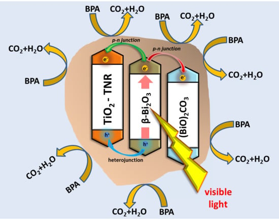
2.3. Proposed Charge Carrier Migration Cascade

The edge of VB (EVB) and CB (ECB) of TiO2 and β-Bi2O3 was calculated by the Mulliken electronegativity theory (Equation (3)) [49,50]:
E VB = X E e + 0.5 × E BG
In this equation, X presents the electronegativity of a semiconductor. Corresponding to Xu and Schoonen [50], the value for TiO2 is 5.81 eV and 6.21 eV for Bi2O3. Ee is free electrons energy on the hydrogen scale and equals 4.5 eV. BG energy of a semiconductor is presented as EBG. In this study, these values were extracted from the results of UV-Vis DR measurements. The obtained EBG energies for TNR, TNP, a-TNR and β-Bi2O3 samples are 3.28, 3.24, 3.4 and 2.45 eV (Figure 5). The conduction band edge (ECB) can be calculated by means of Equation (4):
E CB = E VB E BG
Calculated EVB values of TNP, TNR and a-TNR are 2.95, 2.99 and 3.11 eV, while ECB value for all equals −0.29 eV. The EVB and ECB energies for pure Bi2O3 are 2.93 and 0.48 eV, respectively. XRD analysis confirmed that in a-TNR + Bi and TNR + Bi composites, (BiO)2CO3 was also present. Based on a literature report [45], the EBG of (BiO)2CO3 is 3.1 eV; hence, the calculated ECB and EVB values of (BiO)2CO3 are 3.32 and 0.16 eV, respectively (Equations (1) and (2)).
As already mentioned above, we can see that the low CB gap edge of 0.48 eV in pure β-Bi2O3 cannot provide enough negative potential for the excited electrons to scavenge the adsorbed O2 (E (O2/O2) = −0.33 V vs. NHE and E (O2/O2H) = −0.05 V vs. NHE) [51,52,53]. This means that the generated charge carries are not participating in the reaction, therefore their recombination occurs. This was well-demonstrated in the results of electrochemical measurements and bisphenol A degradation runs, and confirms that pure β-Bi2O3 is not suitable to successfully act as a catalyst in AOPs under visible-light illumination. In the case of the TNP + Bi and TNR + Bi samples, the Bi2O3 VB edge is positioned lower than the TiO2 VB, therefore the transfer of holes, generated under illumination with visible-light, from the Bi2O3VB to the TiO2 VB is thermodynamically possible. In this way, the lifetime of the generated charge carriers is prolonged and results in increased catalytic activity of the composites. In the case of the a-TNR + Bi composite, one can see that the TiO2 VB edge is positioned lower than the Bi2O3 VB edge. Consequently, due to thermodynamic constraints, visible-light generated holes cannot be transported from the Bi2O3 VB to the TiO2 VB upon a heterojunction.
It has to be further considered that between the tightly bonded p-type semiconductor Bi2O3 and the n-type semiconductor TiO2, a p–n junction can be formed [16]. Due to its lower work function, the Fermi level of the p-type Bi2O3 more negative than that of the n-type TiO2 [15,54]. After close chemical contact between Bi2O3 and TiO2, the Bi2O3 Fermi level is moved up and the TiO2 Fermi level is moved down until an inner electric field and equilibrium state of Fermi levels (EF) is established between the Bi2O3 and TiO2 [55,56]. Due to the p–n junction, the visible-light generated electrons (e) in the Bi2O3 CB can be transferred to the TiO2 CB, resulting in a prolonged lifetime of the charge carriers in the Bi2O3, generated under visible-light illumination, and consequently increased TiO2 + Bi2O3 catalytic activity in comparison to Bi2O3.
As explained above, (BiO)2CO3 is also present in the a-TNR + Bi and TNR + Bi composites. In these samples, a p–n junction between the p-type semiconductor β-Bi2O3 and the n-type semiconductor (BiO)2CO3 can be established as well. The p–n junction results in an equilibrium of Fermi levels (EF) of (BiO)2CO3 and β-Bi2O3 and the formation of an inner electric field at the interface between the components. Visible-light generated electrons from the β-Bi2O3 CB can transfer to the (BiO)2CO3 CB, thus prolonging the lifetime of the charge carriers in β-Bi2O3 generated under visible-light illumination.
Considering the results of UV-Vis DR measurements (Figure 5), the role of β-Bi2O3 in all composites is to act as a photosensitizer under visible-light illumination, because the TiO2 EBG and (BiO)2CO3 EBG are not appropriate to generate charge carriers under illumination with visible-light. TiO2 and (BiO)2CO3 (in a-TNR + Bi and TNR + Bi samples) act as scavengers of generated charge carriers in β-Bi2O3, thus prolonging their lifetime, since the electron-hole pair recombination is hindered. This was confirmed by electrochemical measurements and photocatalytic BPA degradation runs.

3. Materials and Methods

3.1. Catalyst Preparation

3.1.1. TiO2 Support Preparation

To obtain TiO2 nanorods (TNR), TiO2 powder (DT-51, provided by Crystal Company, Thann, France, 2 g) was dispersed in NaOH (10 M, 150 mL) and heated for 24 h to 130 °C in a 200 mL Teflon-lined autoclave. Centrifugation was employed to separate the obtained white precipitate from the reaction solution. To neutralize the obtained product, we further washed the wet cake several times with deionized water. Afterwards, it was protonated with HCl (0.1 M) solution and again washed several times with deionized water. The obtained product was dried under cryogenic conditions in a vacuum. This material is denoted as a-TNR. The obtained a-TNR powder was further calcined in air for 2 h at 500 °C to obtain anatase TiO2 nanorods (TNR). TiO2 nanoparticles (TNP) were obtained by calcination of DT-51 at 500 °C in air for 2 h.

3.1.2. Bi2O3 and TiO2–Bi2O3 Composite Preparation

To prepare pure bismuth oxide (Bi2O3) and TiO2–Bi2O3 composites, we used a solution combustion method. To synthesize pure β-Bi2O3, Bi(NO3)3·5H2O (Honeywell Fluka, Charlotte, CA, USA, 2.9 g) and C6H8O7·H2O (Merck, Darmstadt, Germany, 1.471 g) were dissolved in HNO3 (Merck, Darmstadt, Germany, 0.04 M, 10 mL). After stirring for 1 h, Pluronic® P-123 (Sigma-Aldrich, St. Louis, MO, USA, 0.04 g) was added. After another 4 h of stirring, the suspension transferred into a ceramic cup. The ceramic cup was placed inside an oven and heated to 300 °C for 24 h. Afterwards, it was allowed to cool down naturally. In the case of the TiO2–Bi2O3 composite synthesis, 1 g of TiO2 support (TNP, a-TNR or TNR) was added into the HNO3 suspension of Bi(NO3)3·5H2O, C6H8O7·H2O and Pluronic® P-123. The suspension was stirred for another 3 h before heating to 300 °C for 24 h with the same temperature ramp as in case of pure Bi2O3 (120 °C/h). The nominal weight ratio between Ti and Bi was 1:0.4. The samples are denoted as TNP + Bi, a-TNR + Bi, TNR + Bi, and Bi2O3.

3.2. Characterization Methods

Nitrogen adsorption and desorption isotherms of prepared catalysts were obtained with a Micromeritics analyzer (model TriStar II 3020, Norcross, GA, USA). The isotherms were obtained at −196 °C and used to calculate the specific surface area (SBET, calculated based on Brunauer, Emmett and Teller theory (BET)), total pore volume, and average pore size of catalysts. Before the measurements, the samples were degassed (Micromeritics SmartPrep degasser, Norcross, GA, USA) in two steps in a stream of nitrogen (Linde, Munich, Germany, purity 6.0). The first step was carried out for 60 min at 90 °C, which was followed by the second step at 180 °C for 240 min.
The chemical composition and morphology of synthesized materials were examined by a Carl Zeiss field-emission scanning electron microscope (model FE-SEM SUPRA 35 VP, Oberkochen, Germany) equipped with an energy Oxford Instruments dispersive detector (model Inca 400, Abringdon, Oxfordshire, UK).
PANanalytical X‘pert PRO MPD diffractometer (Cu Kα1 radiation (1.54056 Å) in reflection geometry, Almero, The Netherlands) was employed to collect XRD patterns of prepared materials. The scan range was between 20° and 90° in increments of 0.034°. To identify the crystalline phases of measured materials we used X-ray powder diffraction patterns and PDF standards from the International Centre for Diffraction Data (ICDD).
To obtain UV-Vis diffuse reflectance spectra of the examined catalysts a Perkin Elmer spectrophotometer (Lambda 35 UV-Vis equipped with RSA-PE-19M Praying Mantis accessory for powdered samples, Waltham, MA, USA) was used. White reflectance standard Spectralon© was used for the background correction.
A three-electrode electrochemical cell and Metrohm Autolab potentiostat/galvanostat (model PGSTAT30, Ultrecht, The Netherlands) and were used to determine the photo-response characteristics of prepared materials under intermittent visible-light illumination (LED SCHOTT KL 1600 lamp, Mainz, Germany, (λmax = 450 nm)) with 0 V bias potential (vs. SCE). The electrolyte was an aqueous solution of 0.1 M KOH. A drop (10 μL) of catalyst–ethanol suspension (12.5 mg catalyst diluted in 2.5 mL of absolute ethanol (Sigma Aldrich, St. Louis, MO, USA)) was dropped onto the surface of working electrode of the DRP-150 screen-printed electrode (DropSens, Asturias, Spain). As a reference electrode, we used the calomel electrode HI5412 from HANNA instruments (Woonsocket, RI, USA) and as a counter electrode, we used a platinum electrode.

3.3. Catalyst Activity Tests

A 250 mL Lenz batch slurry reactor (LF60) was employed to conduct the experiments at atmospheric pressure and constant reaction temperature. A thermostat (Julabo, model F25/ME, Selbach, Germany) was employed to keep the temperature at 20 °C. During the whole experiment was the bisphenol A solution (10 mg of bispenol A dissolved in 1 L of ultrapure water (18.2 MΩ cm)) purged (45 L/h) with purified air. To prevent the sedimentation of catalyst particles we stirred the solution with a magnetic stirrer at 600 rpm. The concentration of the catalyst was 125 mg/L. To establish the sorption process equilibrium, the reaction suspension was kept for 30 min in the dark (“dark” period). After “dark” period, the Philips 150 W halogen lamp (λmax =  520 nm) was switched on. A UV cut-off filter at λ = 410 nm from Rosco (E-Colour #226: U.V. filter, Stamford, CT, USA, Figure S1 in Supplementary Information) was used to guarantee that the catalyst was illuminated only by visible-light. The lamp was immersed vertically in the center of the Lenz reactor in a quartz jacket which allowed us to cool it with water.
A Thermo Scientific high performance liquid chromatography (HPLC) instrument (model Spectra, Waltham, MA, USA) was used to measure temporal BPA conversion during the photocatalytic runs. In 5 to 30 min intervals, 1.5 mL aqueous-phase samples were collected and before HPLC measurements filtered through a 0.2 μm membrane filter. BDS Hypersil C18 2.4 μm column (100 mm × 4.6 mm) equipped with a universal column protection system was used for the HPLC measurements. The measurements were carried out in the isocratic analytical mode. The column was thermostated at 30 °C. The flow rate of the mobile phase (70% of methanol and 30% of ultrapure water) was 0.5 mL/min and UV detection was performed at λ = 210 nm.
A Teledyne Tekmar total organic carbon analyzer (model Torch, Mason, OH, USA) was used to measure the total organic carbon content in fresh and treated BPA solutions. For this purpose, a high-temperature (750 °C) catalytic oxidation (HTCO) method was employed. The results were used to determine the level of mineralization (TOCM). Each measurement was repeated three times, and the observed error of repetitions was within ± 1%.

4. Conclusions

In all composites, the β-Bi2O3 phase was generated and the structural properties of TiO2 supports were only marginally influenced by the composite preparation procedure. During the synthesis of TNR + Bi and a-TNR + Bi composites, the supplied heat energy was not sufficient to completely transform bismuth carbonate into β-Bi2O3, therefore the derived solids were composed of TiO2, β-Bi2O3 and (BiO)2CO3. A heterojunction between β-Bi2O3 and TiO2 in the TNP + Bi and TNR + Bi composites supports the transfer of visible-light generated holes from the β-Bi2O3 VB to the upper-lying TiO2 VB. The a-TNR + Bi composite is not thermodynamically feasible, since the a-TNR VB is lower than the β-Bi2O3 VB due to the larger BG energy of a-TNR in comparison to other TiO2 supports. In all composites, a p–n junction between β-Bi2O3 and TiO2 enables the transfer of visible-light generated electrons in the β-Bi2O3 CB to the TiO2 CB. In the TNR + Bi composite, a third component ((BiO)2CO3) was also present that can support TiO2 in its role as a scavenger for visible-light generated charge carriers. This was confirmed by obtaining higher photocatalytic activity of BPA degradation in the presence of TNR + Bi composite compared to TNP + Bi sample containing a negligible quantity of (BiO)2CO3.
The obtained results show that the solution combustion synthesis procedure is an appropriate and robust method for the production of visible-light active TiO2 based catalysts, regardless of which TiO2 support is used. The procedure is user-friendly, the temperature of the synthesis is low and the synthesis time is short. By implementing the solution combustion synthesis procedure for producing visible-light active TiO2 based photocatalysts, the use of AOPs for wastewater treatment on industrial scale will be promoted.

Supplementary Materials

The following are available online at https://www.mdpi.com/2073-4344/10/4/395/s1, Figure S1: UV-Vis DR spectra of Philips 150 W halogen lamp (λmax = 520 nm), LED SCHOTT KL 1600 lamp (λmax = 450 nm) and UV cut-off filter foil (Rosco E-Colour #226: U.V. filter), Figure S2: Photoluminescence (PL) emission spectra of the prepared materials (Perkin Elmer, model LS-55).

Author Contributions

Conceptualization, G.Ž. and A.P.; validation, G.Ž. and A.P.; investigation, G.Ž.; resources, A.P.; writing—original draft preparation, G.Ž.; writing—review and editing, G.Ž. and A.P.; visualization, G.Ž.; supervision, G.Ž.; project administration, G.Ž.; funding acquisition, A.P. All authors have read and agreed to the published version of the manuscript.

Funding

The authors gratefully acknowledge the Slovenian Research Agency (ARRS) for financial support through Research Program No. P2-0150.

Acknowledgments

Kristijan Lorber and Janvit Teržan are kindly acknowledged for their assistance in catalyst synthesis and catalyst activity screening. Petar Djinović is acknowledged for helpful discussions.

Conflicts of Interest

The authors declare no conflict of interest.

References

  1. Zhao, J.C.; Wu, K.Q.; Oikawa, K.; Hidaka, H.; Serpone, N. Photoassisted Degradation of Dye Pollutants. 3. Degradation of the Cationic Dye Rhodamine B in Aqueous Anionic Surfactant/TiO2 Dispersions under Visible Light Irradiation:  Evidence for the Need of Substrate Adsorption on TiO2 Particles. Environ. Sci. Technol. 1998, 32, 2394–2400. [Google Scholar] [CrossRef]
  2. Andreozzi, R.; Caprio, V.; Insola, A.; Marotta, R. Advanced oxidation processes (AOP) for water purification and recovery. Catal. Today 1999, 53, 51–59. [Google Scholar] [CrossRef]
  3. Deng, Y.; Zhao, R. Advanced Oxidation Processes (AOPs) in Wastewater Treatment. Curr. Pollut. Rep. 2015, 1, 167–176. [Google Scholar] [CrossRef] [Green Version]
  4. Hashimoto, K.; Irie, H.; Fujishima, A. TiO2 photocatalysis: A historical overview and future prospects. Jpn. J. Appl. Phys. 2005, 12, 8269–8285. [Google Scholar] [CrossRef]
  5. Nakata, K.; Fujishima, A. TiO2 photocatalysis: Design and applications. J. Photoch. Photobiol. C 2012, 13, 169–189. [Google Scholar] [CrossRef]
  6. Ge, M.; Cao, C.; Huang, J.; Li, S.; Chen, Z.; Zhang, K.-Q.; Al-Deyab, S.S.; Ali, Y. A review of one-dimensional TiO2 nanostructured materials for environmental and energy applications. J. Mater. Chem. A 2016, 4, 6772–6801. [Google Scholar] [CrossRef]
  7. Zhang, J.; Xu, Q.; Feng, Z.; Li, M.; Li, C. Importance of the Relationship between Surface Phases and Photocatalytic Activity of TiO2. Angew. Chem. 2008, 9, 1766–1769. [Google Scholar] [CrossRef]
  8. Magalhães, P.; Andrade, L.; Nunes, O.C.; Mendes, A. Titanium Dioxide Photocatalysis: Fundamentals and Application on Photoinactivation. Rev. Adv. Mater. Sci. 2017, 51, 91–129. [Google Scholar]
  9. Schneider, J.; Matsuoka, M.; Takeuchi, M.; Zhang, J.; Horiuchi, Y.; Anpo, M.; Bahnemann, D.W. Understanding TiO2 Photocatalysis: Mechanisms and Materials. Chem. Rev. 2014, 114, 9919–9986. [Google Scholar] [CrossRef]
  10. Jiang, H.Y.; Cheng, K.; Lin, J. Crystalline metallic Au nanoparticle-loaded α-Bi2O3 microrods for improved photocatalysis. Phys. Chem. Chem. Phys. 2012, 14, 12114–12121. [Google Scholar] [CrossRef]
  11. Hameed, A.; Montini, T.; Gombac, V.; Fornasiero, P. Surface Phases and Photocatalytic Activity Correlation of Bi2O3/Bi2O4-x Nanocomposite. J. Am. Chem. Soc. 2008, 130, 9658–9659. [Google Scholar] [CrossRef] [PubMed]
  12. Li, L.; Huang, X.; Hu, T.; Wang, J.; Zhang, W.; Zhang, J. Synthesis of three-dimensionally ordered macroporous composite Ag/Bi2O3–TiO2 by dual templates and its photocatalytic activities for degradation of organic pollutants under multiple modes. New J. Chem. 2014, 38, 5293–5302. [Google Scholar] [CrossRef]
  13. Wu, Y.; Lu, G.; Li, S. The Doping Effect of Bi on TiO2 for Photocatalytic Hydrogen Generation and Photodecolorization of Rhodamine B. J. Phys. Chem. C 2009, 113, 9950–9955. [Google Scholar] [CrossRef]
  14. Zhao, X.; Liu, H.J.; Qu, J.H. Photoelectrocatalytic degradation of organic contaminants at Bi2O3/TiO2 nanotube array electrode. Appl. Surf. Sci. 2011, 257, 4621–4624. [Google Scholar] [CrossRef]
  15. Wei, N.; Cui, H.; Wang, C.; Zhang, G.; Song, Q.; Sun, W.; Song, X.; Sun, M.; Tian, J. Bi2O3 nanoparticles incorporated porous TiO2 films as an effective p-n junction with enhanced photocatalytic activity. J. Am. Ceram. Soc. 2017, 100, 1339–1349. [Google Scholar] [CrossRef]
  16. Huang, Y.; Wei, Y.; Wang, J.; Luo, D.; Fan, L. Controllable fabrication of Bi2O3/TiO2 heterojunction with excellent visible-light responsive photocatalytic performance. J. Appl. Surf. Sci. 2017, 423, 119–130. [Google Scholar] [CrossRef]
  17. Reddy, N.L.; Emin, S.; Valant, M.; Shankar, M.V. Nanostructured Bi2O3/TiO2 photocatalyst for enhanced hydrogen production. Int. J. Hydrogen Energy 2017, 42, 6627–6636. [Google Scholar] [CrossRef]
  18. La, J.; Huang, Y.; Luo, G.; Lai, J.; Liu, C.; Chu, G. Synthesis of bismuth oxide nanoparticles by solution combustion method. Particul. Sci. Technol. 2013, 31, 287–290. [Google Scholar] [CrossRef]
  19. Anilkumara, M.; Pasricha, R.; Ravic, V. Synthesis of bismuth oxide nanoparticles by citrate gel method. Ceram. Int. 2005, 31, 889–891. [Google Scholar] [CrossRef]
  20. Mallahi, M.; Shokuhfar, A.; Vaezi, M.R.; Esmaeilirad, A.; Mazinani, V. Synthesis and characterization of Bismuth oxide nanoparticles via sol-gel method. Am. J. Eng. Res. 2014, 3, 162–165. [Google Scholar]
  21. Wu, C.; Shen, L.; Huang, Q.; Zhang, Y.-C. Hydrothermal synthesis and characterization of Bi2O3 nanowires. Mater. Lett. 2011, 65, 1134–1136. [Google Scholar] [CrossRef]
  22. Yang, Q.; Li, Y.; Yin, Q.; Wang, P.; Cheng, Y. Hydrothermal synthesis of bismuth oxide needles. Mater. Lett. 2002, 55, 46–49. [Google Scholar] [CrossRef]
  23. Hernandez-Delgadillo, R.; Velasco-Arias, D.; Martinez-Sanmiguel, J.J.; Diaz, D.; Zumeta-Dube, I.; Arevalo-Niño, K.; Cabral-Romero, C. Bismuth oxide aqueous colloidal nanoparticles inhibit Candida albicans growth and biofilm formation. Int. J. Nanomed. 2013, 8, 1645–1652. [Google Scholar]
  24. De Sousa, V.C.; Morelli, M.R.; Kiminami, R.H.G. Bismuth oxide aqueous colloidal nanoparticles inhibit Candida albicans growth and biofilm formation. Ceram. Int. 2000, 26, 561–564. [Google Scholar] [CrossRef]
  25. Zywitzki, D.; Jing, H.; Tuysuz, H.; Chan, C.K.J. High surface area, amorphous titania with reactive Ti3+ through a photo-assisted synthesis method for photocatalytic H2 generation. Mater. Chem. A 2017, 5, 10957–10967. [Google Scholar] [CrossRef] [Green Version]
  26. Ohtani, B.; Ogawa, Y.; Nishimoto, S. Photocatalytic activity of amorphous—Anatase mixture of titanium (IV) oxide particles suspended in aqueous solutions. J. Phys. Chem. B 1997, 100, 3746–3752. [Google Scholar] [CrossRef] [Green Version]
  27. Tanaka, K.; Capule, M.F.V.; Hisanaga, T. Effect of crystallinity of TiO2 on its photocatalytic action. Chem. Phys. Lett. 1991, 187, 73–76. [Google Scholar] [CrossRef]
  28. Stone, V.F.; Davis, R.J. Synthesis, characterization, and photocatalytic activity of titania and niobia mesoporous molecular sieves. Chem. Mater. 1998, 10, 1468–1474. [Google Scholar] [CrossRef]
  29. Gao, L.; Zhang, Q. Effects of amorphous contents and particle size on the photocatalytic properties of TiO2 nanoparticles. Scr. Mater. 2001, 44, 1195–1198. [Google Scholar] [CrossRef]
  30. Li, J.; Chen, C.; Zhao, J.; Zhu, H.; Orthman, J. Photodegradation of dye pollutants on TiO2 nanoparticles dispersed in silicate under UV–VIS irradiation. J. Appl. Catal. B Environ. 2002, 37, 331–338. [Google Scholar] [CrossRef]
  31. Randorn, C.; Wongnawa, S.; Boonsin, P. Bleaching of methylene blue by hydrated titanium dioxide. ScienceAsia 2004, 30, 149–156. [Google Scholar] [CrossRef]
  32. Liu, A.R.; Wang, S.M.; Zhao, Y.R.; Zheng, Z. Low-temperature preparation of nanocrystalline TiO2 photocatalyst with a very large specific surface area. Mater. Chem. Phys. 2006, 99, 131–134. [Google Scholar] [CrossRef]
  33. Žerjav, G.; Arshad, M.S.; Djinović, P.; Zavašnik, J.; Pintar, A. Electron trapping energy states of TiO2–WO3 composites and their influence on photocatalytic degradation of bisphenol A. Appl. Catal. B Environ. 2017, 2009, 273–284. [Google Scholar] [CrossRef]
  34. Kominami, H.; Oki, K.; Kohno, M.; Onoue, S.I.; Kera, Y.; Ohtani, B. Novel solvothermal synthesis of niobium(V)oxide powders and their photocatalytic activity in aqueous suspensions. J. Mater. Chem. 2001, 11, 604–609. [Google Scholar] [CrossRef]
  35. Benmami, M.; Chhor, K.; Kanaev, A.V. Supported nanometric titanium oxide sols as a new efficient photocatalyst. J. Phys. Chem. B 2005, 109, 19766–19771. [Google Scholar] [CrossRef]
  36. Wu, C.; Zhao, X.; Ren, Y.; Yue, Y.; Hua, W.; Cao, Y.; Tang, Y.; Gao, Z. Gas-phase photo-oxidations of organic compounds over different forms of zirconia. J. Mol. Catal. A Chem. 2005, 229, 233–239. [Google Scholar] [CrossRef]
  37. Zhang, Z.; Maggard, P.A. Investigation of photocatalytically-active hydrated forms of amorphous titania, TiO2 × nH2O. J. Photochem. Photobiol. A 2007, 186, 8–13. [Google Scholar] [CrossRef]
  38. Li, J.; Liu, S.; He, Y.; Wang, J. Adsorption and degradation of the cationic dyes over Co doped amorphous mesoporous titania–silica catalyst under UV and visible light irradiation. Microporous Mesoporous Mater. 2008, 115, 416–425. [Google Scholar] [CrossRef]
  39. Li, Y.; Sasaki, T.; Shimizu, Y.; Koshizaki, N. Hexagonal-Close-Packed, Hierarchical Amorphous TiO2 Nanocolumn Arrays: Transferability, Enhanced Photocatalytic Activity, and Superamphiphilicity without UV Irradiation. J. Am. Chem. Soc. 2008, 130, 14755–14762. [Google Scholar] [CrossRef]
  40. Tueysuez, H.; Chan, C.K. Preparation of amorphous and nanocrystalline sodium tantalum oxide photocatalysts with porous matrix structure for overall water splitting. Nano Energy 2013, 2, 116–123. [Google Scholar] [CrossRef]
  41. Grewe, T.; Tueysuez, H. Designing photocatalysts for hydrogen evolution: Are complex preparation strategies necessary to produce active catalysts? ChemSusChem 2015, 8, 3084–3091. [Google Scholar] [CrossRef]
  42. Erjavec, B.; Kaplan, R.; Pintar, A. Effects of heat and peroxide treatment on photocatalytic activity of titanate nanotubes. Catal. Today 2015, 241, 15–24. [Google Scholar] [CrossRef]
  43. Žerjav, G.; Arshad, M.S.; Djinović, P.; Junkar, I.; Kovač, J.; Zavašnik, J.; Pintar, A. Improved electron–hole separation and migration in anatase TiO2 nanorod/reduced graphene oxide composites and their influence on photocatalytic performance. Nanoscale 2017, 9, 4578–4592. [Google Scholar] [CrossRef] [PubMed] [Green Version]
  44. Astuti, Y.; Fauziyah, A.; Nurhayati, S.; Wulansari, A.D.; Andianingrum, R.; Hakim, A.R.; Bhaduri, G. Synthesis of α-Bismuth oxide using solution combustion method and its photocatalytic properties. IOP Conf. Ser. Mater. Sci. Eng. 2016, 107, 12006–12013. [Google Scholar] [CrossRef] [Green Version]
  45. Zhu, G.; Liu, Y.; Hojamberdiev, M.; Han, J.; Rodríguez, J.; Bilmes, S.A.; Liu, P. Thermodecomposition synthesis of porous β-Bi2O3/Bi2O2CO3 heterostructured photocatalysts with improved visible light photocatalytic activity. New J. Chem. 2015, 39, 9557–9568. [Google Scholar] [CrossRef]
  46. Zhang, J.; Zhou, P.; Liu, J.; Yu, J. New understanding of the difference of photocatalytic activity among anatase, rutile and brookite TiO2. Phys. Chem. Chem. Phys. 2014, 16, 20382–20386. [Google Scholar] [CrossRef]
  47. Dette, C.; Pérez-Osorio, M.A.; Kley, C.S.; Punke, P.; Patrick, C.E.; Jacobson, P.; Giustino, F.; Jung, S.J.; Kern, K. TiO2 Anatase with a Bandgap in the Visible Region. Nano Lett. 2014, 14, 6533–6538. [Google Scholar] [CrossRef]
  48. Rahman, M.; MacElroy, D.; Dowling, D.P. Influence of the physical, structural and chemical properties on the photoresponse property of magnetron sputtered TiO2 for the application of water splitting. J. Nanosci. Nanotechnol. 2011, 11, 8642–8651. [Google Scholar] [CrossRef]
  49. Butler, M.A.; Ginley, D.S. Prediction of Flatband Potentials at Semiconductor-Electrolyte Interfaces from Atomic Electronegativities. J. Electrochem. Soc. 1978, 125, 228–232. [Google Scholar] [CrossRef]
  50. Xu, Y.; Schoonen, M.A.A. The absolute energy positions of conduction and valence bands of selected semiconducting minerals. Am. Mineral. 2000, 85, 543–556. [Google Scholar] [CrossRef]
  51. Abe, R.; Takami, H.; Murani, N.; Ohtani, B. Pristine simple oxides as visible light driven photocatalysts: Highly efficient decomposition of organic compounds over platinum-loaded tungsten oxide. J. Am. Chem. Soc. 2008, 130, 7780–7781. [Google Scholar] [CrossRef] [PubMed]
  52. Liu, G.; Wan, L.; Sun, C.; Wang, X.; Chen, Z.; Smith, S.C.; Cheng, H.M.; Lu, G.Q. Band-to-band visible-light photon excitation and photoactivity induced by homogeneous nitrogen doping in layered titanates. Chem. Mater. 2009, 21, 1266–1274. [Google Scholar] [CrossRef]
  53. Ayekoe, P.Y.; Robert, D.; Gone, D.L. Environ. Preparation of effective TiO2/Bi2O3 photocatalysts for water treatment. Chem. Lett. 2016, 14, 387–393. [Google Scholar] [CrossRef]
  54. Yi, S.; Yue, X.; Xu, D.; Liu, Z.; Zhao, F.; Wangab, D.; Lin, Y. Study on photogenerated charge transfer properties and enhanced visible-light photocatalytic activity of p-type Bi2O3/n-type ZnO heterojunctions. New J. Chem. 2015, 39, 2917–2924. [Google Scholar] [CrossRef]
  55. Zhang, Z.; Shao, C.; Li, X.; Wang, C.; Zhang, M.; Liu, Y. Electrospun Nanofibers of p-Type NiO/n-Type ZnO Heterojunctions with Enhanced Photocatalytic Activity. ACS Appl. Mater. Interfaces 2010, 2, 2915–2923. [Google Scholar] [CrossRef]
  56. Dai, G.; Yu, J.; Liu, G. Synthesis and Enhanced Visible-Light Photoelectrocatalytic Activity of p−n Junction BiOI/TiO2 Nanotube Arrays. J. Phys. Chem. C 2011, 115, 7339–7346. [Google Scholar] [CrossRef]
Figure 1. SEM micrographs of prepared catalysts.
Catalysts 10 00395 g001
Figure 2. SEM-EDX elemental mapping conducted on prepared TiO2–Bi2O3 composites.
Catalysts 10 00395 g002
Figure 3. Nitrogen adsorption–desorption isotherms (a) and BJH (Barrett, Joyner and Halenda method) pore size distribution of synthesized catalysts (b).
Catalysts 10 00395 g003
Figure 4. X-ray powder diffraction (XRD) patterns of the prepared materials (green vertical lines belong to tetragonal β-Bi2O3 (JCPDS 00-027-0050), blue vertical lines to (BiO)2CO3 (JCPDS 00-025-1464) and red vertical lines to anatase TiO2 (JCPDS 00-021-1272).
Catalysts 10 00395 g004
Figure 5. Spectra of UV-Vis Diffuse Reflectance (DR) measurements performed on synthesized catalysts.
Catalysts 10 00395 g005
Figure 6. Photocurrent densities at photoelectrode measured under intermittent visible-light (LED light) irradiation in 0.1 M KOH.
Catalysts 10 00395 g006
Figure 7. Photocatalytic degradation of bisphenol A (BPA) (c0 = 10 mg/L) in the presence of prepared materials (ccat. = 125 mg/L) under visible-light irradiation.
Catalysts 10 00395 g007
Table 1. Brunauer, Emmett and Teller theory (BET) specific surface area (SBET), average pore diameter (dpore), total pore volume (Vpore), and average crystallite size of (BiO)2CO3 (JCPDS 00-041-1488), anatase TiO2 (JCPDS 00-021-1272), and tetragonal β-Bi2O3 (JCPDS 00-027-0050) in synthesized materials.
SampleSBET
(m2/g)
dpore
(nm)
Vpore
(cm3/g)
Average Crystallite Size (nm)
Anatase TiO2Tetragonal Β-Bi2O3(Bio)2CO3
TNP8613.70.2920--
TNP + Bi7013.40.252025-
a-TNR27810.50.85---
a-TNR + Bi21711.10.69-a N.D.a N.D.
TNR10519.30.5714--
TNR + Bi8117.50.4015N.D.18
Bi2O34.716.50.02-31-
a Not determined.
Table 2. Results of SEM-EDX analysis of the prepared catalysts.
SampleContent (wt. %)Ti:Bi Actual Ratio *
OTiBi
TNP + Bi4540151:0.37
a-TNR + Bi4041191:0.46
TNR + Bi4443131:0.30
* Nominal wt. ratio Ti:Bi = 1:0.4.
Table 3. The content of carbon accumulated on the surface of catalysts before (TCfresh) and after (TCspent) photocatalytic degradation of bisphenol A. TOC removal (TOCR) represents a sum of TOC accumulation (TOCA) and TOC mineralization (TOCM).
SampleTCfreshTCspentTCspent-TCfreshTOCRTOCMTOCA
(%)
TNP0.160.200.040--
TNP + Bi0.160.320.1623.020.03.0
a-TNR0.861.60.740--
a-TNR + Bi0.901.20.321.016.05.0
TNR0.230.680.4511.04.07.0
TNR + Bi0.360.870.5151.043.08.0
Bi2O30.340.50.264.01.42.6

