Article

Modifying the Surface Structure of Perovskite-Based Catalysts by Nanoparticle Exsolution

1
TU Wien, Institute of Materials Chemistry, Getreidemarkt 9/165, 1060 Vienna, Austria
2
TU Wien, Institute of Chemical Technologies and Analytics, Getreidemarkt 9/164-EC, 1060 Vienna, Austria
3
TU Wien, USTEM, Wiedner Hauptstr. 8-10/E057-02, 1040 Vienna, Austria
*
Author to whom correspondence should be addressed.
Catalysts 2020, 10(3), 268; https://doi.org/10.3390/catal10030268
Submission received: 6 February 2020 / Revised: 24 February 2020 / Accepted: 27 February 2020 / Published: 1 March 2020

Abstract

:
In heterogeneous catalysis, surfaces decorated with uniformly dispersed, catalytically-active (nano)particles are a key requirement for excellent performance. Beside standard catalyst preparation routines—with limitations in controlling catalyst surface structure (i.e., particle size distribution or dispersion)—we present here a novel time efficient route to precisely tailor catalyst surface morphology and composition of perovskites. Perovskite-type oxides of nominal composition ABO3 with transition metal cations on the B-site can exsolve the B-site transition metal upon controlled reduction. In this exsolution process, the transition metal emerges from the oxide lattice and migrates to the surface where it forms catalytically active nanoparticles. Doping the B-site with reducible and catalytically highly active elements, offers the opportunity of tailoring properties of exsolution catalysts. Here, we present the synthesis of two novel perovskite catalysts Nd0.6Ca0.4FeO3-δ and Nd0.6Ca0.4Fe0.9Co0.1O3-δ with characterisation by (in situ) XRD, SEM/TEM and XPS, supported by theory (DFT+U). Fe nanoparticle formation was observed for Nd0.6Ca0.4FeO3-δ. In comparison, B site cobalt doping leads, already at lower reduction temperatures, to formation of finely dispersed Co nanoparticles on the surface. These novel perovskite-type catalysts are highly promising for applications in chemical energy conversion. First measurements revealed that exsolved Co nanoparticles significantly improve the catalytic activity for CO2 activation via reverse water gas shift reaction.

Graphical Abstract

1. Introduction

In heterogeneous catalysis, controllable surface properties and a maximum amount of stable uniformly-dispersed catalytically highly active sites on the surface of a porous material are of key importance. Typically, catalysts consist of metal, alloy, or oxide nanoparticles embedded in an oxide support material. Depending on the type of catalytic reaction, active sites are either just nanoparticles themselves or the combination of nanoparticles and oxide support. Ideally, catalysts exhibit long-term stability and activity during reaction. Therefore, resistance to catalyst poisons, inhibition of carbon deposition (blocking of active sites), and prevention of particle agglomeration and sintering (loss of active surface area) is essential.
Typically, these structures are prepared by deposition, impregnation or precipitation techniques [1,2] followed by catalyst activation prior to reactions via oxidation and reduction [3]. Although these approaches are applied widely, they offer limited control over size, distribution, and anchorage of deposited species, not only during preparation but also during catalyst activation or operation, and they might be time consuming and costly [4].
Alternatively, an emerging concept is to grow the nanoparticles in situ, by reduction or during catalytic reaction, directly from the (porous) oxide backbone support itself [4,5,6]. Perovskites (nominal composition ABO3 with A and B being a large and small cation, respectively) can incorporate catalytically highly active elements as cations on the B-site of the perovskite lattice (e.g., Ni [4,7], Fe [4,8], Co [9], Cu [4,9], Pt [10], Pd [10,11]). Upon exposure to reducing conditions, these elements can be partly exsolved as nanoparticles, thus opening the possibility of in situ growth of active catalysts [12], see sketch in Figure 1. In comparison to traditional deposition techniques, this process produces finer and higher dispersed catalyst nanoparticles [4,13,14] and is more time- and cost-effective, as it does not require multiple ‘deposition’ steps or expensive precursors [15]. Furthermore, it has been shown that nanoparticles formed by exsolution exhibit improved sintering stability during catalytic reaction [16]. In addition, due to a possible reversibility of the nanoparticle exsolution process, particle agglomeration can be avoided by reoxidation cycles [17], hence, greatly enhancing the catalyst lifetime [12,18].
Mechanisms for nanoparticle exsolution from perovskites were investigated already by multiple groups [4,11,19,20,21]. It is generally accepted that exsolution catalysts need easily reducible dopant cations [22], such as Ru, Co, Pd, or Ni [23], that will form metallic deposits on the perovskite surface. Thus, depending on temperature and oxygen chemical potential in the gas phase (i.e., the strength of reduction), dopants and in some cases also lattice cations are reduced and exsolved as nanoparticles [8,24]. As an explanation for exsolution mechanisms, Neagu et al. [4] proposed that oxygen vacancies created by reduction destabilize the perovskite lattice, especially when their concentration is high and when additionally A-site cation vacancies are present. Such combined oxygen and A-site cation vacancy formations may locally cause spontaneous exsolution of B-site species in an attempt to re-establish stoichiometry across all sites. Oh et al. [19] implied that the morphological evolution of nanoparticles could be explained using a simple energy-based model, which accounts for interplay between surface free energy and strain energy induced by the included metal nucleate. By quantitative strain field modelling, they could demonstrate that this provides the driving force for exsolution processes. Similarly, Han and co-workers applied classical nucleation theory to the exsolution process and found the strain between metal particle and supporting oxide being a potential influencing factor for the particle size.
Usually, formation of nanoparticles on the surface is accomplished via a reductive treatment. For example, Arrivé et al. [25] showed for Ni doped LaSrTiO3 that pre-reduction in H2 at 1573 K leads to exsolution of Ni particles on the surface of solid oxide electrochemical cells leading to improved electrochemical performance. Additionally, Papargyriou and Irvine demonstrated Ni exsolution from Ni-doped La0.75Sr0.25Cr0.5Fe0.5O3 perovskite by H2 reduction [14]. Nanoparticles with a size of 30–50 nm were formed on the surface, leading to an improvement of catalytic properties of the material. Similarly, Sun et al. [13] could observe Ni nanoparticle exsolution from Ni-doped La0.7Sr0.3CrO3 upon pre-reduction in H2. Most of the recent studies on exsolution phenomena are reported and studied by the electrochemical community (mainly with respect to fuel cell technology), but utilization of this effect for preparing tailored heterogeneous catalyst materials is still rare—even though the initial idea came indeed from the catalysis community [12].
Here we present synthesis and characterization of the novel perovskites Nd0.6Ca0.4FeO3-δ and Nd0.6Ca0.4Fe0.9Co0.1O3-δ. Their exsolution properties (by reductive treatment in humidified H2) were studied utilizing (in situ) X-ray diffraction (XRD), X-ray photoelectron spectroscopy (XPS), scanning electron microscopy (SEM), and transmission electron microscopy (TEM). To highlight the effect of nanoparticle exsolution on catalytic activity, the novel perovskites were then tested regarding their suitability for reverse water gas shift reaction (rWGS), for the Co-doped perovskite reductive treatment caused the formation of finely dispersed metallic Co nanoparticles, which greatly enhanced the rWGS reactivity.

2. Results and Discussion

2.1. Materials Design

For synthesis of the novel materials, we made a judicious choice of composition of the perovskite host lattice, enabling us future use of a variety of catalytically-active elements as dopants. An optimized perovskite composition enables exsolution with controlled nanoparticle size. For the A-site neodymium and calcium have been chosen with a 6:4 ratio. Usually La is one of the most common elements for A-site. However, to avoid XPS peak overlap with some future potentially interesting dopant elements (especially Ni) when performing in situ near ambient pressure XPS (NAP-XPS) measurements, we used Nd instead. Acceptor doping of the A-site with Ca introduces electronic defects (holes) and oxygen vacancies, which improves the electron and oxygen anion conductivity of the material. Density Functional Theory (DFT) calculations (utilizing WIEN2k [26]) suggest that this electronic defects are delocalized over both oxygen and iron atoms. Oxygen participation in the delocalization is revealed by empty O-p states above the Fermi level, that in the bulk are occupied (details, Section 2.2), which is also in accordance with results from X-ray absorption spectroscopy (XAS) on a very similar material (La0.6Sr0.4FeO3-δ) [27]. The contribution of iron atoms is indicated by a reduction of their magnetic moment (around 0.5 µB) corresponding to partial oxidation. Additionally, a Jahn–Teller distortion for the iron atoms in question is found (where four bonds get shortened by about 6.9%, while the other two are elongated by about 6.6%), which corresponds to the changed electronic configuration and the smaller size of Fe4+ ions.
Variation of the A-site dopant concentration allows additional fine-tuning of the exsolution process [28]. In a preliminary study, we saw that for perovskites without B-site doping the temperature necessary for exsolution is higher with an increasing amount of Ca doping. The B-site cation is iron, which was replaced by 10% of cobalt for the doped catalyst. As discussed later in detail, the undoped perovskite exhibited iron nanoparticle exsolution at 948 K. When the material is additionally doped on the B-site with Co, exsolution of both Fe and Co nanoparticles, or even formation of FeCo alloy nanoparticles would be possible. Therefore, we settled for the considerably high amount of Ca A-site doping of 40%. Consequently, the host lattice is expected to be quite stable, leading to preferential exsolution of cobalt upon reductive treatment of the doped material.
After synthesis, Nd0.6Ca0.4FeO3-δ and Nd0.6Ca0.4Fe0.9Co0.1O3-δ, were characterized by XRD for identification of the crystal structure. For both freshly synthesized materials (Figure 2a,b bottom diffractograms), only the pure perovskite phase was observed. All the reflexes in the pattern at RT correspond to this phase, they are marked with P in the graph, and their hkl-indices are given in Figure 2a. The patterns of the undoped and doped material were almost identical, indicating equivalent structures. The main reflexes were at 2θ of 32.9°, 47.0°, and 58.7°, respectively. Rietveld refinement in combination with database structures for similar materials was utilized to propose the crystal structure. An orthorhombic lattice (lattice parameters: a = 5.533 Å, b = 7.726 Å, c = 5.449 Å) with space group Pnma (Nr. 62) was revealed. For an ideal cubic perovskite structure, ionic radii of all elements have to fulfil a certain size relation, which is reflected by a Goldschmidt tolerance factor of 1. For our materials, this factor is slightly below 1, leading to a distortion of the ideal structure (tilted B-site coordination octahedrons) and a reduced symmetry [29].

2.2. DFT Calculations

To gain insight on the effect of A-site doping of NdFeO3 with Ca on atomic and electronic structure of the perovskite, DFT calculations of NdFeO3 and Nd0.5Ca0.5FeO3 were performed. A previous theoretical study of such a system by Wang et al. [30] treated the 4f electrons of Nd in the frozen core approximation.
Here, however, a full potential (FP-(L)APW+lo) calculation was done. The doped material shows more strongly distorted Fe–O-octahedra compared to the octahedra in bulk NdFeO3: while Fe–O bond lengths in the bulk materials differ only by 1.1%, the longest Fe–O bond in the doped material is 5.4% and 14.5% longer than the shortest one for Fe3+ and Fe4+, respectively. DFT+U finds a bandgap of 2.38 eV for bulk NdFeO3, while the doped material is metallic. The Fermi level is shifted into bands that are fully occupied in the bulk due to the doping—as shown in the density of states (DOS) in Figure 3 (states, that are occupied in the bulk, are empty in the doped material because replacing Nd3+ with Ca2+ reduces the number of valence electrons). Both oxygen p states and iron d states contribute to the empty states directly above the Fermi level, indicating a partial delocalization of the electron hole over many oxygen atoms on one hand and a partial oxidation of Fe atoms (Fe4+) on the other hand.
The Fe atoms in the bulk unit cell are pair wise equivalent (spin-up and spin-down atoms differ only with respect to the magnetic structure of their next nearest Nd neighbors, which shows that the magnetic ordering on the Nd sublattice has virtually no effect on the Fe atoms in the bulk)—in the doped material, this equivalency is lifted: The iron atoms (both spin-up and spin-down) with slightly larger Fe–Ca distances show a reduction of their respective magnetic moments (going from 4.0 µB to 3.4 µB). This hints toward a partial oxidation of Fe3+ atoms. For Fe3+ the larger moment derives from fully occupied spin-up states; this occupation is reduced for Fe4+. The partial oxidation is further evidenced by a Jahn–Teller distortion around the oxidized atoms (four bonds are shortened by 6.9%, two bonds are elongated by 6.6%) corresponding to the change in electronic configuration and the smaller ionic radius of Fe4+.

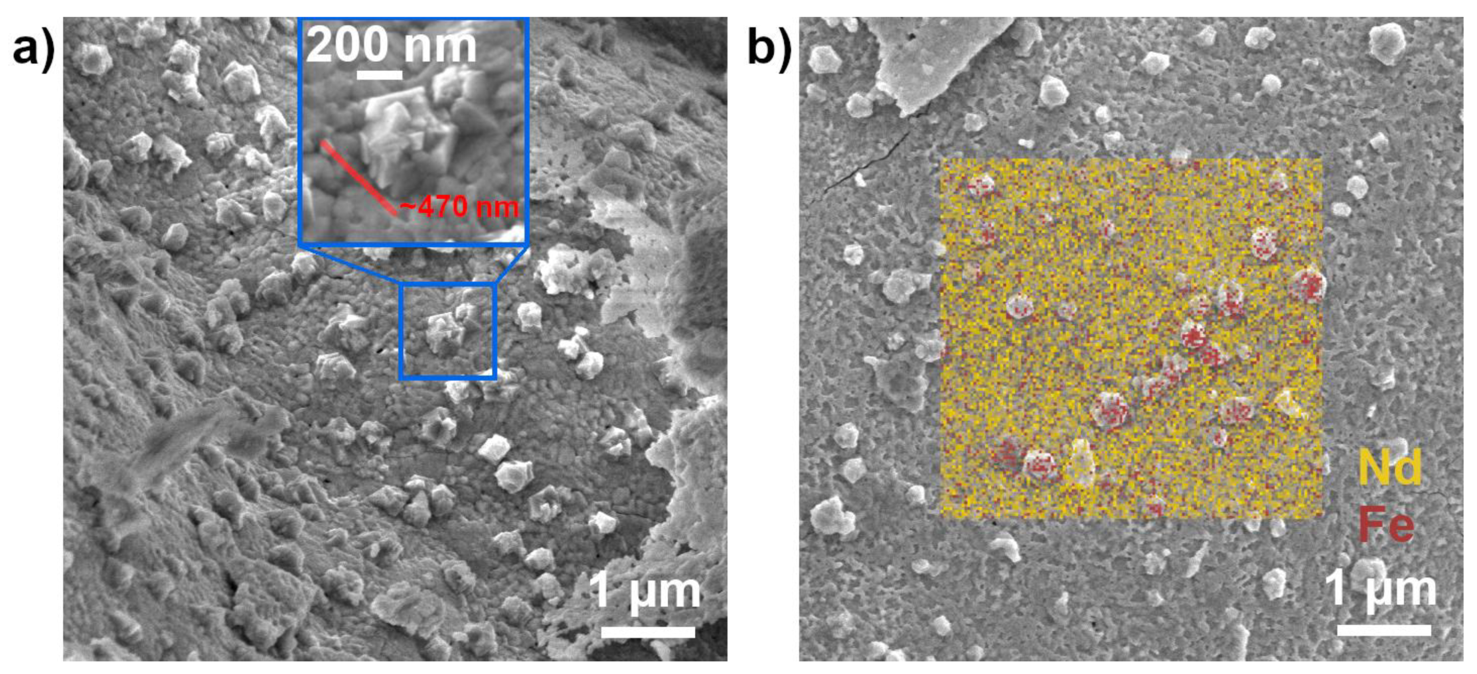
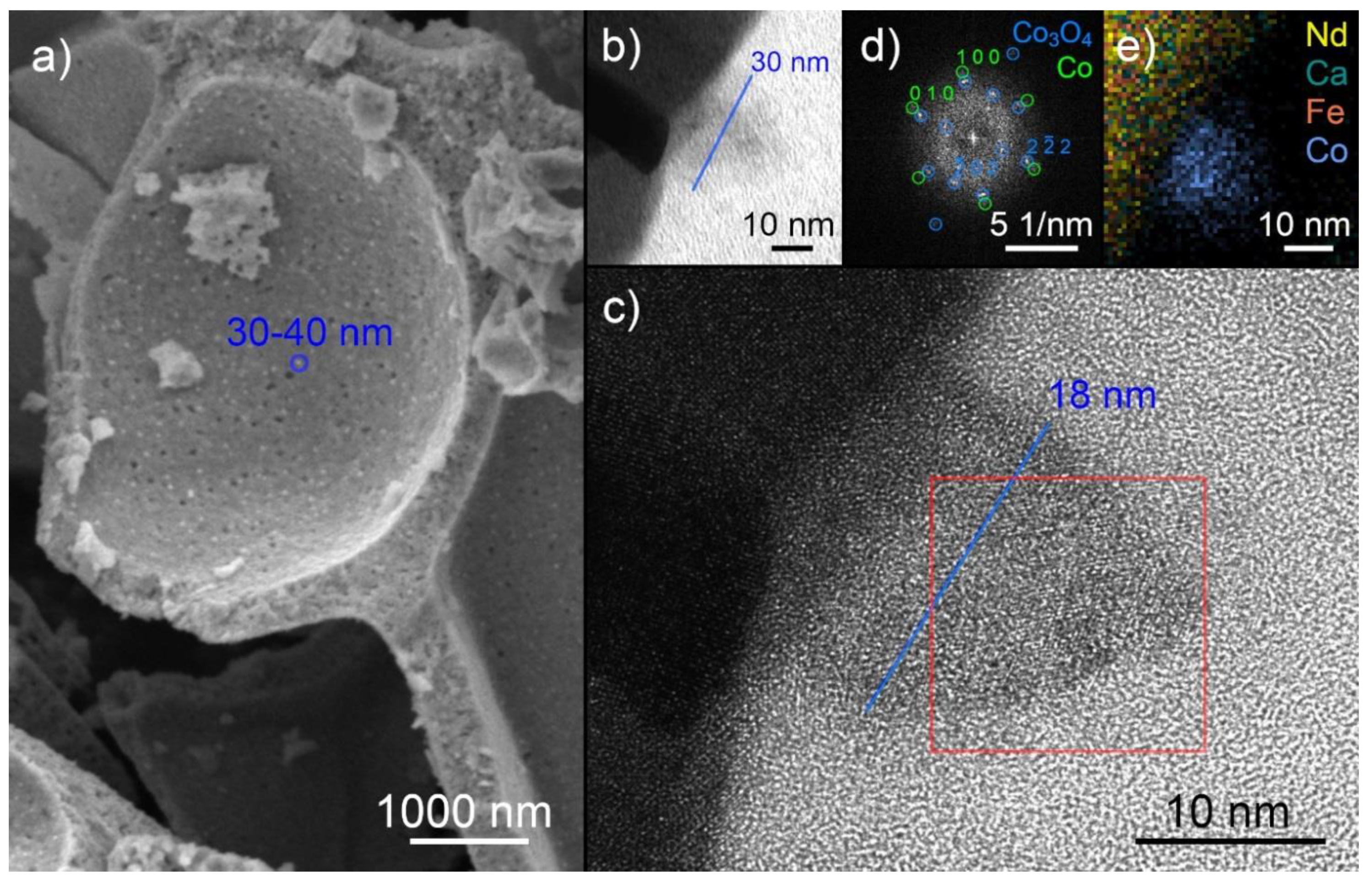
2.3. Exsolution Properties

For the following reductive treatment we used humidified H2 at 1 bar with a H2/H2O ratio of ~32:1, which corresponds to an oxygen partial pressure of only 5.3 × 10⁻²⁶ bar. The role of water in the gas phase is to provide an oxygen source for a well-defined oxygen partial pressure (pO2, explanation see SI). This is required to be able to exactly compare our results to future planned electrochemical studies and to other work on exsolution in literature [31]. For the undoped perovskite, in situ XRD measurements revealed the formation of a metallic Fe bcc phase above 948 K at 2θ = 44.4° (Figure 2a). Important is, that although we observed nanoparticle exsolution, the perovskite itself stayed intact, as indicated by the XRD pattern. SEM combined with energy dispersive X-ray spectroscopy (EDX) confirmed the formation of larger Fe particles with a size of ~470 nm on the surface, Figure 4. It is clearly visible that the exsolved particles are well shaped crystals growing from the surface (Figure 4a) and that they primarily consist of iron (Figure 4b). Formation of metallic iron on the surface was also visible in the Fe 2p XPS signal at 707.0 eV (SI, Figure S1) [8].
For comparison, doping with cobalt facilitated exsolution already at lower temperatures. Upon reductive treatment a Fe/Co bcc diffraction line evolved between 823 and 848 K in the XRD pattern at 2θ = 44.8° (Figure 2b). Unfortunately, it was not possible to distinguish clearly between Fe and Co with XRD due to an overlap of the diffraction lines of both metals. SEM images showed the formation of finely dispersed nanoparticles on the surface with an average size of 30 nm to 40 nm, Figure 5a.
Further analysis of the doped perovskite with TEM and scanning TEM (STEM) combined with EDX revealed the presence of Co nanoparticles on the surface. For these studies, the thin film samples were reduced at 923 K in humidified hydrogen (2.5% H2/2.5% H2O/balance Ar) atmosphere in a tube furnace. A core-shell structure is visible in Figure 5b. In high resolution mode (HRTEM, Figure 5c), lattice planes can be observed, the Fourier transformation of this area (FFT, Figure 5d) reveals two phases, Co3O4 and Co. These observations can be explained by the air exposure of the sample between exsolution and TEM analysis. The original particle consisted of metallic cobalt. Its surface was oxidized upon air exposure, forming the cobalt oxide shell with a diameter of 30 nm. The core is the remaining unoxidized cobalt and has a diameter of 18 nm. An EDX mapping (Figure 5e) verified that the predominant metal in the particle was cobalt. The cobalt concentration (color intensity) is higher in the core and lower in the shell, in agreement with the proposed Co and Co3O4 phases. Formation of metallic cobalt upon nanoparticle exsolution could also be confirmed with in situ NAP-XPS. A metallic Co2p signal at ~776 eV evolved when exposing the perovskite to H2/H2O at 873 K (SI, Figure S2).
Our results highlight that, already, the host perovskite lattice is capable of Fe particle exsolution at higher reduction temperatures (>948 K). The addition of an easier reducible dopant element (here, cobalt) leads to its preferential exsolution at significantly lower temperatures (823 K) in the form of finely dispersed nanoparticles. It cannot be ruled out that by further reduction at even higher temperatures also iron may be exsolved to the surface, either in form of additional Fe nanoparticles, or by alloy formation with the already present Co particles (further studies are planned). In a related study, Zhu and co-workers only observed CoFe alloy formation at temperatures above 1023 K from La0.5Sr0.5Co0.45Fe0.45Nb0.1O3-δ [32].
In comparison to our studied perovskites, other groups reported generally much higher reduction temperatures for nanoparticle exsolution. Gao et al. showed Ni exsolution from La0.52Sr0.28Ti0.94Ni0.06O3-δ after reduction at 1173 K [33]. Similarly, Kim et al. highlighted Ni exsolution from La0.2Sr0.7Ti0.9Ni0.1O3−δ at the same temperature [34]. Earlier work of Irvine and co-workers demonstrated nanoparticle formation (Fe, Ni, Cu) upon reduction at temperatures between 1173 K and 1273 K [4]. Recently, they proved the possibility to lower the exsolution temperature by inducing lattice strain to perovskite thin films resulting in Ni exsolution at 823 K [25]. A lower temperature was also reported by Steiger et al. for LaFe0.8Ni0.2O3-δ with Ni nanoparticle exsolution by reduction at 873 K [35]. Joo et al. reduced a cobalt doped Mn-based perovskite at 1023 K to achieve Co nanoparticle exsolution [36].
A reason for the reported high exsolution temperatures is that these studies are mainly conducted in the field of solid oxide fuel cells with their operation temperatures in the 873–1173 K range. For catalytic applications, however, lowering the exsolution temperature is utmost important, especially for future application in industrial processes. Moreover, it has been shown that nanoparticles formed by exsolution exhibit improved sintering stability [16], preventing one of the major problems of catalyst deactivation in heterogeneous catalysis.

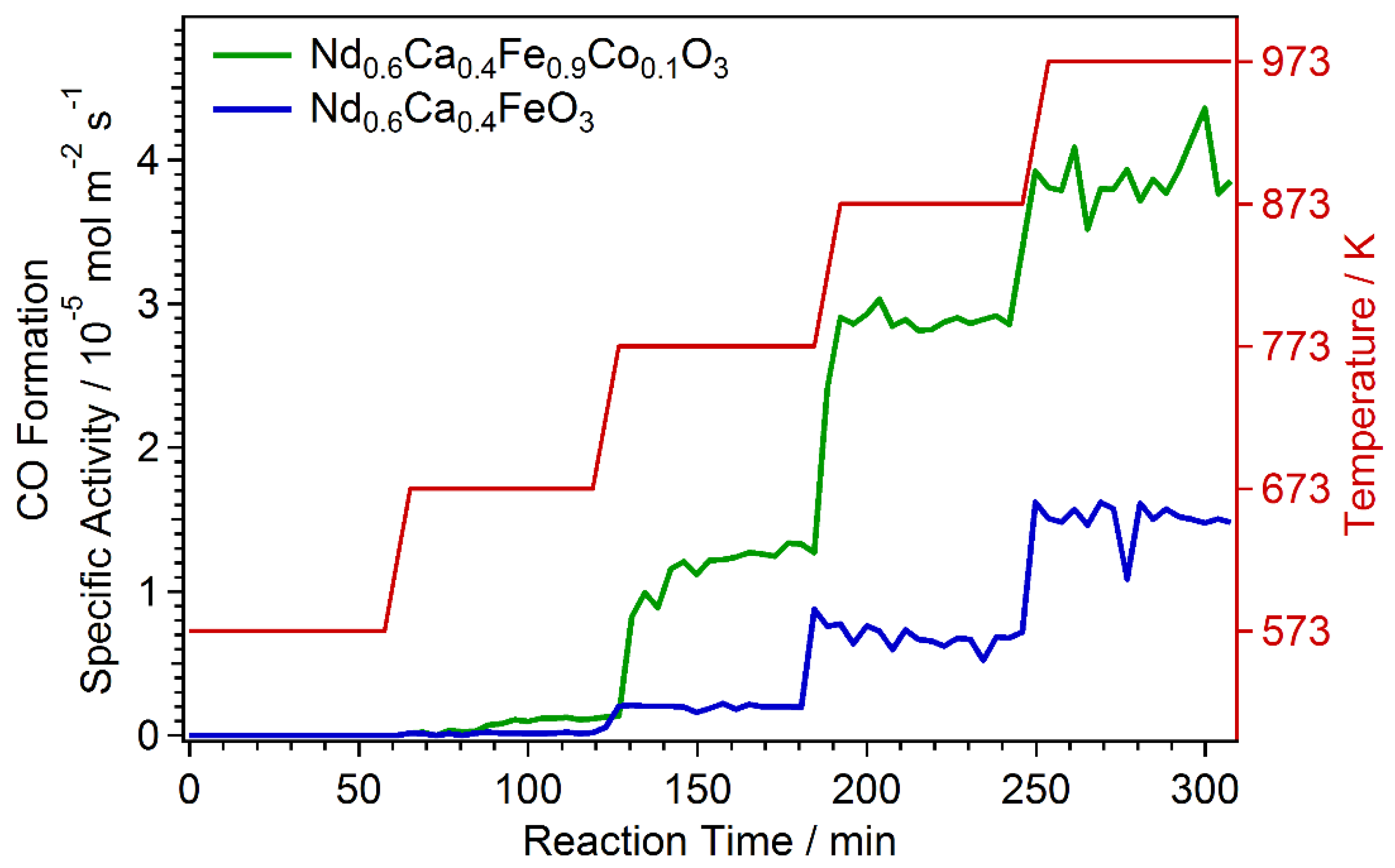
2.4. Catalytic Test Measurements

As outlined in the introduction, nanoparticle exsolution is an elegant and fast route for catalyst preparation. To demonstrate the capability of our tailored perovskite materials, first catalytic tests for CO2 activation via rWGS reaction were performed. We have chosen rWGS as it can be considered a promising technology for converting CO2 to CO, which can then be further converted via CO hydrogenation to liquid fuels (e.g., diesel, gasoline, and alcohols). This approach has the advantage of high throughput rates, selectivity, and technological readiness [37]. Furthermore, we have shown in previous work that perovskites are excellent materials for CO2 activation, e.g., by electrocatalytic CO2 reduction [31].
After introducing the starting reactant gas flow with a CO2/H2 ratio of 1:1, the temperature was increased stepwise up to 973 K. Onset of CO formation could be observed above 573 K, Figure 6. Already the undoped perovskite Nd0.6Ca0.4FeO3-δ showed catalytic activity (blue line). This was expected, as iron is known to be catalytically active for rWGS [37]. However, additional doping with Co and the resulting Co nanoparticle exsolution from Nd0.6Ca0.4Fe0.9Co0.1O3-δ resulted in a strong improvement of the catalytic activity (green line). Additionally, for Co, it has been shown that it is catalytically highly active for rWGS [37]. The combination of an already active perovskite host material as support and the catalytically active dopant material (here Co), that forms finely dispersed nanoparticles on the surface, leaded to a strong improvement of catalytic reactivity.
By correlating nanoparticle exsolution with catalytic testing, we could demonstrate the impressive capabilities of perovskite based catalysts. In combination with doping of the B-site by catalytically highly active elements these materials enable manifold routes for catalyst engineering, opening the possibility of tailoring catalyst surfaces to actual needs.

3. Materials and Methods

3.1. Synthesis of Novel Perovskites

The perovskite powders were synthesized via the Pechini route [38]. The cations were mixed in the desired stoichiometric ratio. The starting materials were Nd2O3 (99.999%, Alfa Aesar, Haverhill, MA, USA), CaCO3 (99.999%, Alfa Aesar, Haverhill, MA, USA), Fe (99.99%, Sigma-Aldrich, St. Louis, MO, USA), and Co (99.995%, Sigma-Aldrich, St. Louis, MO, USA). The compounds were weighted accordingly and dissolved in HNO3 (double distilled, 65%, Merck, Darmstadt, Germany). Cation complexes were formed by adding citric acid (99.9998% trace metals pure, Fluka, Honeywell International, Charlotte, NC, USA) in a molar ratio of 1.2 with respect to the cations. After evaporation of H2O, the resulting gel was heated until self-ignition took place. The obtained powder was calcined for three hours at 1073 K. After grinding (i.e., with a mortar to obtain homogeneous powders for better characterization), the resulting products were used for the (in situ) XRD, standard XPS, SEM studies, and catalytic testing.
For the in situ NAP-XPS and TEM experiments, thin film samples of Nd0.6Ca0.4Fe0.9Co0.1O3 were prepared. Therefore, the powder was pressed into a pellet using a uniaxial press. Sintering of the pellet was carried out at 1523 K for 12 h. Dense perovskite thin films were then produced by pulsed laser deposition (PLD), using the Nd0.6Ca0.4Fe0.9Co0.1O3 pellet as a target. Ablation was carried out at 873 K on (100)-oriented yttria stabilized zirconia (YSZ) single crystals (CrysTec GmbH, Berlin, Germany) (10 × 10 × 0.5 mm) as substrates in 0.04 mbar oxygen background pressure using a KrF excimer laser (Lambda COMPexPro 201F, λ = 248 nm, Coherent, Santa Clara, CA, USA) with 400 mJ laser pulses at 5 Hz.

3.2. Characterization Methods

Standard XPS measurements were performed using a photoelectron spectrometer (SPECS Surface Nano Analysis GmbH, Berlin, Germany) equipped with a PHOIBOS-100-MCD-5 hemispherical energy analyser and an X-ray source XR50 with a double Al/Mg anode. For measurements, the samples were supported onto double-sided conducting carbon tape.
In situ XPS measurements were performed on a lab-based in situ NAP-XPS system equipped with a Phoibos 150 NAP hemispherical analyzer and a XR 50 MF X-ray source (microfocus), all from SPECS (Berlin, Germany). Spectra were recorded with monochromatic Al Kα radiation and data were analyzed with CasaXPS software (Casa Software Ltd., Teignmouth, UK). Peaks were fitted after Shirley or linear background subtraction with Gauss−Lorentz sum functions. Peak positions and full width at half-maximum (FWHM) were left unconstrained. Peak positions were referenced either to the valence band signal (Fermi edge) or to the carbon signal.
The powder XRD measurements were carried out on a PANalytical X’Pert Pro diffractometer (Malvern Panalytical, Malvern, UK) in Bragg–Brentano geometry using a mirror for separating the Cu Kα1,2 radiation and an X’Celerator linear detector. For the in situ experiments, an XRK 900 chamber (Anton Paar, Graz Austria) was used. The pristine samples were pre-treated in O2 at 875 K for 30 min. After cooling to room temperature, the atmosphere was changed to humidified H2 (using a bubbler at room temperature, p = 1 bar, H2:H2O ≈ 32:1) and the temperature was increased stepwise by 25 K. At each step, an in situ XRD measurement was performed after waiting for 30 min. The data were analyzed using the HighScore Plus software (Malvern Panalytical, Malvern, UK) [39] and the PDF-4+ 2019 database (ICDD - International Centre for Diffraction Data, Newtown Square, PA, USA) [40]. The reflexes were assigned according to database entries.
The SEM experiments were done on a Quanta 250 FEGSEM (FEI Company, Hillsboro, OR, USA) equipped with an Octane Elite X-ray detector (EDAX Inc, Mahwah, NJ, USA) using an acceleration voltage of 5 kV to achieve sufficient surface-sensitivity. The images were recorded using secondary electrons.
For the (scanning) TEM experiments, the sample was first coated with protective C and Pt layers. Then, an ultra-thin sample was cut containing single, well-separated nanoparticles using a focused Ga ion beam in a Quanta 200 3D DBFIB (FEI Company, Hillsboro, OR, USA). The TEM measurements were performed with an acceleration voltage of 200 kV in a Tecnai F20 microscope (FEI Company, Hillsboro, OR, USA) equipped with a RIO camera (Gatan, Pleasanton, CA, USA), an Apollo X-ray detector (EDAX Inc, Mahwah, NJ, USA), and a GIF Tridiem energy filter (Gatan, Pleasanton, CA, USA). First, the high-resolution images were recorded in TEM mode. Then, the X-ray measurements were performed in the same area in STEM mode.

3.3. DFT Calculations

Spin-polarized DFT (DFT+U) calculations were performed using the program package WIEN2k (Institute of Materials Chemistry, TU Wien, Vienna, Austria) [26], which is an implementation of the augmented plane wave + local orbital method [41] treating all electrons in a full potential (FP-(L)APW+lo). The GGA functional PBE [42] was used to treat exchange-correlation with an additional Hubbard-U [43] to account for localized Fe 3d and Nd 4f electrons, respectively. In both cases a value of Ueff = 4eV was used [44,45].
Using the XRD data presented in Section 2.1 (cp. Figure 2a) a unit cell containing four formula units of NdFeO3 was set up. This cell was used to simulate Nd0.5Ca0.5FeO3 (corresponding to a 50% doping) by substituting two Nd atoms with Ca (see supporting information, Figure S3). The atomic positions were optimized until residual forces were below 1 mRy/bohr.
Both Nd and Fe order magnetically: Spin-up and spin-down Fe atoms make up a type G [46] antiferromagnetic sublattice [47], where the spin of any given iron atom is aligned antiparallel to all its nearest neighbors. Although Nd atoms in NdFeO3 show long range antiferromagnetic order for very low temperatures (experiments find ordering for temperatures below 2 K [47,48]), initial calculations were done with a ferromagnetic using setup to save on compute time, since the effect of ferromagnetic Nd ordering on the moments of the other atoms is small (in the order of 0.01 µB). Final calculations were performed with optimized positions from initial runs and antiferromagnetically ordered Nd atoms—since all residual forces remained small (below 1.5 mRy/bohr) no additional structure optimization was carried out.
The choice for atomic sphere radii for all calculations was 2.20, 1.92, and 1.60 bohr for Nd/Ca, Fe, and O respectively. A plane wave cutoff of RKmax = 8 was used to determine the basis set size, where R is the radius of the smallest atomic sphere and Kmax denotes the largest considered vector in reciprocal space. The Brillouin zone of the doped material was sampled using a 9 × 6 × 9 Monkhorst–Pack k-mesh [49].
The calculations of the doped material were compared with results of undoped bulk NdFeO3 [50], derived using the same computational parameters.

3.4. Catalytic Testing

Catalytic tests for CO2 activation via rWGS reaction (CO2 + H2 ↔ CO + H2O) were performed in a 6 mm tubular flow reactor (quartz glass, inner diameter 4 mm) at atmospheric pressure. Online gas analysis was conducted by a Micro-GC (Fusion 3000A, Inficon, Bad Ragaz, Switzerland) which was sampling every ~2 min. The total flow was 12 mL/min, with educt flow of 6 mL/min with a ratio of 1/1 for CO2/H2 and argon added as carrier gas (all gases provided by Messer Group GmbH, Bad Soden, Germany). A blind test was performed without catalyst to rule out any catalytic activity of the reactor itself. For the reactions, the pure perovskite powder catalysts (20–60 mg) were supported directly on a glass wool bed. A PID controller (EMSR EUROTHERM GmbH, Vienna, Austria) was used for control of the reactor heater. For a better comparability of the two perovskites, the CO formation was normalized by the active catalyst surface area (BET area) and is, therefore, given as specific activity (mol/m2s).

4. Conclusions

We have demonstrated that exsolution is an elegant process to produce catalytically active surfaces with well-dispersed metal nanoparticles. This is especially interesting for fast and simple catalyst preparation, as we have shown for Nd0.6Ca0.4FeO3-δ and Nd0.6Ca0.4Fe0.9Co0.1O3-δ. Whereas the undoped material exhibits Fe nanoparticle exsolution at 948 K, the doped material facilitates Co nanoparticle exsolution already starting at 823 K. Furthermore, these nanoparticles are smaller (average size 30–40 nm) and well dispersed over the surface. The lower exsolution temperature makes the material especially interesting for catalytic applications as demonstrated for CO2 activation via rWGS. The undoped Nd0.6Ca0.4FeO3-δ is already active for rWGS and with additional Co doping the perovskite exhibits significantly increased reactivity due to Co nanoparticle exsolution. Our novel materials open unpredicted possibilities for customized engineering of support materials, including doping with catalytically-active elements that are capable of forming nanoparticles on the surface.

Supplementary Materials

The following figure is available online at https://www.mdpi.com/2073-4344/10/3/268/s1, Figure S1. XPS spectra of Nd0.6Ca0.4FeO3, Figure S2. XPS spectra of Nd0.6Ca0.4Fe0.9Co0.1O3, Figure S3. DFT structure of Nd0.5Ca0.5FeO3.

Author Contributions

Conceptualization: C.R. and A.K.O.; validation: L.L., R.R., H.S., J.P., A.N., and S.L.; formal analysis: L.L., J.P., P.B., and T.R.; investigation: L.L., R.R., H.S., J.P., S.L., and T.R.; resources: L.L and H.S.; data curation: L.L., R.R., J.P., and T.R.; writing—original draft preparation: C.R.; writing—review and editing: C.R., A.K.O, A.N., L.L., P.B., and T.R.; visualization: L.L., T.R., and R.R.; supervision: C.R.; project administration: C.R.; funding acquisition: C.R. All authors have read and agreed to the published version of the manuscript.

Funding

This research was funded by the European Research Council (ERC) under the European Union’s Horizon 2020 research and innovation programme, grant agreement no. 755744/ERC—Starting Grant TUCAS.

Acknowledgments

Computational results presented have been achieved using the Vienna Scientific Cluster (VSC).

Conflicts of Interest

The authors declare no conflict of interest.

References

  1. Gorte, R.J.; Vohs, J.M. Nanostructured anodes for solid oxide fuel cells. Curr. Opin. Colloid Interface Sci. 2009, 14, 236–244. [Google Scholar] [CrossRef]
  2. Yates, J.T.; Campbell, C.T. Surface chemistry: Key to control and advance myriad technologies. Proc. Natl. Acad. Sci. USA 2011, 108, 911–916. [Google Scholar] [CrossRef] [Green Version]
  3. Rousseau, S.; Marie, O.; Bazin, P.; Daturi, M.; Verdier, S.; Harle, V. Investigation of Methanol Oxidation over Au/Catalysts Using Operando IR Spectroscopy: Determination of the Active Sites, Intermediate/Spectator Species, and Reaction Mechanism. J. Am. Chem. Soc. 2010, 132, 10832–10841. [Google Scholar] [CrossRef]
  4. Neagu, D.; Tsekouras, G.; Miller, D.N.; Menard, H.; Irvine, J.T.S. In situ growth of nanoparticles through control of non-stoichiometry. Nat. Chem. 2013, 5, 916–923. [Google Scholar] [CrossRef] [Green Version]
  5. Katz, M.B.; Zhang, S.Y.; Duan, Y.W.; Wang, H.J.; Fang, M.H.; Zhang, K.; Li, B.H.; Graham, G.W.; Pan, X.Q. Reversible precipitation/dissolution of precious-metal clusters in perovskite-based catalyst materials: Bulk versus surface re-dispersion. J. Catal. 2012, 293, 145–148. [Google Scholar] [CrossRef]
  6. Tsekouras, G.; Neagu, D.; Irvine, J.T.S. Step-change in high temperature steam electrolysis performance of perovskite oxide cathodes with exsolution of B-site dopants. Energy Environ. Sci. 2013, 6, 256–266. [Google Scholar] [CrossRef]
  7. Kobsiriphat, W.; Madsen, B.D.; Wang, Y.; Shah, M.; Marks, L.D.; Barnett, S.A. Nickel- and Ruthenium-Doped Lanthanum Chromite Anodes: Effects of Nanoscale Metal Precipitation on Solid Oxide Fuel Cell Performance. J. Electrochem. Soc. 2010, 157, B279–B284. [Google Scholar] [CrossRef]
  8. Opitz, A.K.; Nenning, A.; Rameshan, C.; Rameshan, R.; Blume, R.; Haevecker, M.; Knop-Gericke, A.; Rupprechter, G.; Fleig, J.; Kloetzer, B. Enhancing Electrochemical Water-Splitting Kinetics by Polarization-Driven Formation of Near-Surface Iron (0): An In Situ XPS Study on Perovskite-Type Electrodes. Angew. Chem. Int. Ed. 2015, 54, 2628. [Google Scholar] [CrossRef]
  9. Adijanto, L.; Padmanabhan, V.B.; Gorte, R.J.; Vohs, J.M. Polarization-Induced Hysteresis in CuCo-Doped Rare Earth Vanadates SOFC Anodes. J. Electrochem. Soc. 2012, 159, F751–F756. [Google Scholar] [CrossRef] [Green Version]
  10. Tanaka, H.; Uenishi, M.; Taniguchi, M.; Tan, I.; Narita, K.; Kimura, M.; Kaneko, K.; Nishihata, Y.; Mizuki, J. Intelligent catalyst having the self-regenerative function of Pd, Rh and Pt for automotive emissions control. Catal. Today 2006, 117, 321–328. [Google Scholar] [CrossRef]
  11. Katz, M.B.; Graham, G.W.; Duan, Y.W.; Liu, H.; Adamo, C.; Schlom, D.G.; Pan, X.Q. Self-Regeneration of Pd-LaFeO3 Catalysts: New Insight from Atomic-Resolution Electron Microscopy. J. Am. Chem. Soc. 2011, 133, 18090–18093. [Google Scholar] [CrossRef]
  12. Nishihata, Y.; Mizuki, J.; Akao, T.; Tanaka, H.; Uenishi, M.; Kimura, M.; Okamoto, T.; Hamada, N. Self-regeneration of a Pd-perovskite catalyst for automotive emissions control. Nature 2002, 418, 164–167. [Google Scholar] [CrossRef]
  13. Sun, Y.F.; Li, J.H.; Zeng, Y.M.; Amirkhiz, B.S.; Wang, M.N.; Behnamian, Y.; Luo, J.L. A-site deficient perovskite: The parent for in situ exsolution of highly active, regenerable nano-particles as SOFC anodes. J. Mater. Chem. A 2015, 3, 11048–11056. [Google Scholar] [CrossRef]
  14. Papargyriou, D.; Irvine, J.T.S. Nickel nanocatalyst exsolution from (La,Sr)(Cr,M,Ni)O3 (M=Mn,Fe) perovskites for the fuel oxidation layer of Oxygen Transport Membranes. Solid State Ion. 2016, 288, 120–123. [Google Scholar] [CrossRef] [Green Version]
  15. Zhao, Q.; Lorenz, H.; Turner, S.; Lebedev, O.I.; Van Tendeloo, G.; Rameshan, C.; Klotzer, B.; Konzett, J.; Penner, S. Catalytic characterization of pure SnO2 and GeO2 in methanol steam reforming. Appl. Catal. Gen. 2010, 375, 188–195. [Google Scholar] [CrossRef] [Green Version]
  16. Neagu, D.; Oh, T.S.; Miller, D.N.; Menard, H.; Bukhari, S.M.; Gamble, S.R.; Gorte, R.J.; Vohs, J.M.; Irvine, J.T.S. Nano-socketed nickel particles with enhanced coking resistance grown in situ by redox exsolution. Nat. Commun. 2015, 6. [Google Scholar] [CrossRef] [Green Version]
  17. Burnat, D.; Kontic, R.; Holzer, L.; Steiger, P.; Ferri, D.; Heel, A. Smart material concept: Reversible microstructural self-regeneration for catalytic applications. J. Mater. Chem. A 2016, 4, 11939–11948. [Google Scholar] [CrossRef]
  18. Tanaka, H.; Taniguchi, M.; Uenishi, M.; Kajita, N.; Tan, I.; Nishihata, Y.; Mizuki, J.; Narita, K.; Kimura, M.; Kaneko, K. Self-regenerating Rh- and Pt-based perovskite catalysts for automotive-emissions control. Angew. Chem. Int. Ed. 2006, 45, 5998–6002. [Google Scholar] [CrossRef]
  19. Oh, T.S.; Rahani, E.K.; Neagu, D.; Irvine, J.T.S.; Shenoy, V.B.; Gorte, R.J.; Vohs, J.M. Evidence and Model for Strain-Driven Release of Metal Nanocatalysts from Perovskites during Exsolution. J. Phys. Chem. Lett. 2015, 6, 5106–5110. [Google Scholar] [CrossRef] [Green Version]
  20. Haag, J.M.; Barnett, S.A.; Richardson, J.W.; Poeppelmeier, K.R. Structural and Chemical Evolution of the SOFC Anode La0.30Sr0.70Fe0.70Cr0.30O3-δ upon Reduction and Oxidation: An in Situ Neutron Diffraction Study. Chem. Mater. 2010, 22, 3283–3289. [Google Scholar] [CrossRef]
  21. Gotsch, T.; Schlicker, L.; Bekheet, M.F.; Doran, A.; Grunbacher, M.; Praty, C.; Tada, M.; Matsui, H.; Ishiguro, N.; Gurlo, A.; et al. Structural investigations of La0.6Sr0.4FeO3-δ under reducing conditions: Kinetic and thermodynamic limitations for phase transformations and iron exsolution phenomena. RSC Adv. 2018, 8, 3120–3131. [Google Scholar] [CrossRef] [Green Version]
  22. Kwon, O.; Sengodan, S.; Kim, K.; Kim, G.; Jeong, H.Y.; Shin, J.; Ju, Y.W.; Han, J.W. Exsolution trends and co-segregation aspects of self-grown catalyst nanoparticles in perovskites. Nat. Commun. 2017, 8. [Google Scholar] [CrossRef] [PubMed] [Green Version]
  23. Han, H.; Park, J.; Nam, S.Y.; Kim, K.J.; Choi, G.M.; Parkin, S.S.P.; Jang, H.M.; Irvine, J.T.S. Lattice strain-enhanced exsolution of nanoparticles in thin films. Nat. Commun. 2019, 10, 1471. [Google Scholar] [CrossRef] [PubMed]
  24. Gotsch, T.; Kopfle, N.; Grunbacher, M.; Bernardi, J.; Carbonio, E.A.; Havecker, M.; Knop-Gericke, A.; Bekheet, M.F.; Schlicker, L.; Doran, A.; et al. Crystallographic and electronic evolution of lanthanum strontium ferrite (La0.6Sr0.4FeO3-δ) thin film and bulk model systems during iron exsolution. Phys. Chem. Chem. Phys. 2019, 21, 3781–3794. [Google Scholar] [CrossRef]
  25. Arrive, C.; Delahaye, T.; Joubert, O.; Gauthier, G. Exsolution of nickel nanoparticles at the surface of a conducting titanate as potential hydrogen electrode material for solid oxide electrochemical cells. J. Power Sources 2013, 223, 341–348. [Google Scholar] [CrossRef]
  26. Blaha, P.; Schwarz, K.; Madsen, G.K.H.; Kvasnicka, D.; Luitz, J.; Laskowski, R.; Tran, F.; Marks, L.D. WIEN2k: An Augmented Plave Wave plus Local Oribtals Program for Calculating Crystal Properties; Vienna University of Technology: Wien, Austria, 2018. [Google Scholar]
  27. Mueller, D.N.; Machala, M.L.; Bluhm, H.; Chueh, W.C. Redox activity of surface oxygen anions in oxygen-deficient perovskite oxides during electrochemical reactions. Nat. Commun. 2015, 6. [Google Scholar] [CrossRef] [Green Version]
  28. Lee, W.; Han, J.W.; Chen, Y.; Cai, Z.; Yildiz, B. Cation Size Mismatch and Charge Interactions Drive Dopant Segregation at the Surfaces of Manganite Perovskites. J. Am. Chem. Soc. 2013, 135, 7909–7925. [Google Scholar] [CrossRef]
  29. Geller, S. Crystallographic Studies of Perovskite-like Compounds V: Relative Ionic Sizes. Acta Crystallogr. 1957, 10, 248–251. [Google Scholar] [CrossRef] [Green Version]
  30. Wang, Y.; Ren, W.; Liu, P.R.; Zhao, H.J.; Chen, J.; Deng, J.X.; Xing, X.R. Improved conductivity of NdFeO3 through partial substitution of Nd by Ca: A theoretical study. Phys. Chem. Chem. Phys. 2015, 17, 29097–29102. [Google Scholar] [CrossRef] [Green Version]
  31. Opitz, A.K.; Nenning, A.; Rameshan, C.; Kubicek, M.; Goetsch, T.; Blume, R.; Haevecker, M.; Knop-Gericke, A.; Rupprechter, G.; Kloetzer, B.; et al. Surface Chemistry of Perovskite-Type Electrodes During High Temperature CO2 Electrolysis Investigated by Operando Photoelectron Spectroscopy. ACS Appl. Mater. Interfaces 2017, 9, 35847–35860. [Google Scholar] [CrossRef]
  32. Chen, X.Y.; Ni, W.J.; Wang, J.; Zhong, Q.; Han, M.F.; Zhu, T.L. Exploration of Co-Fe alloy precipitation and electrochemical behavior hysteresis using Lanthanum and Cobalt co- substituted SrFeO3-δ SOFC anode. Electrochim. Acta 2018, 277, 226–234. [Google Scholar] [CrossRef]
  33. Gao, Y.; Lu, Z.H.; You, T.L.; Wang, J.; Xie, L.; He, J.Q.; Ciucci, F. Energetics of Nanoparticle Exsolution from Perovskite Oxides. J. Phys. Chem. Lett. 2018, 9, 3772–3778. [Google Scholar] [CrossRef]
  34. Kim, K.J.; Han, H.; Defferriere, T.; Yoon, D.; Na, S.; Kim, S.J.; Dayaghi, A.M.; Son, J.; Oh, T.S.; Jang, H.M.; et al. Facet-Dependent in Situ Growth of Nanoparticles in Epitaxial Thin Films: The Role of Interfacial Energy. J. Am. Chem. Soc. 2019, 141, 7509–7517. [Google Scholar] [CrossRef] [PubMed]
  35. Steiger, P.; Nachtegaal, M.; Krocher, O.; Ferri, D. Reversible Segregation of Ni in LaFe0.8Ni0.2O3±δ During Coke Removal. Chemcatchem 2018, 10, 4456–4464. [Google Scholar] [CrossRef]
  36. Joo, S.; Kwon, O.; Kim, K.; Kim, S.; Kim, H.; Shin, J.; Jeong, H.Y.; Sengodan, S.; Han, J.W.; Kim, G. Cation-swapped homogeneous nanoparticles in perovskite oxides for high power density. Nat. Commun. 2019, 10, 697. [Google Scholar] [CrossRef]
  37. Daza, Y.A.; Kuhn, J.N. CO2 conversion by reverse water gas shift catalysis: Comparison of catalysts, mechanisms and their consequences for CO2 conversion to liquid fuels. RSC Adv. 2016, 6, 49675–49691. [Google Scholar] [CrossRef]
  38. Pechini, M.P. Method of Preparing Lead and Alkaline Earth Titanates and Niobates and Coating Method Using the Same to form a Capacitor. U.S. Patent 3,330,697, 11 July 1967. [Google Scholar]
  39. Degen, T.; Sadki, M.; Bron, E.; König, U.; Nénert, G. The HighScore suite. Powder Diffr. 2014, 29, S13–S18. [Google Scholar] [CrossRef] [Green Version]
  40. ICDD PDF-4+ 2019; International Centre for Diffraction Data: Newtown Square, PA, USA, 2018.
  41. Karsai, F.; Tran, F.; Blaha, P. On the importance of local orbitals using second energy derivatives for d and f electrons. Comput. Phys. Commun. 2017, 220, 230–238. [Google Scholar] [CrossRef]
  42. Perdew, J.P.; Burke, K.; Ernzerhof, M. Generalized gradient approximation made simple. Phys. Rev. Lett. 1996, 77, 3865–3868. [Google Scholar] [CrossRef] [Green Version]
  43. Anisimov, V.I.; Zaanen, J.; Andersen, O.K. Band Theory and Mott Insulators—Hubbard-U Instead of Stoner-I. Phys. Rev. B 1991, 44, 943–954. [Google Scholar] [CrossRef] [Green Version]
  44. Kraushofer, F.; Jakub, Z.; Bichler, M.; Hulva, J.; Drmota, P.; Weinold, M.; Schmid, M.; Setvin, M.; Diebold, U.; Blaha, P.; et al. Atomic-Scale Structure of the Hematite alpha-Fe2O3 (1(1)over-bar02) “R-Cut” Surface. J. Phys. Chem. C 2018, 122, 1657–1669. [Google Scholar] [CrossRef] [PubMed] [Green Version]
  45. Nilsson, F.; Sakuma, R.; Aryasetiawan, F. Ab initio calculations of the Hubbard U for the early lanthanides using the constrained random-phase approximation. Phys. Rev. B 2013, 88. [Google Scholar] [CrossRef]
  46. Wollan, E.O.; Koehler, W.C. Neutron Diffraction Study of the Magnetic Properties of the Series of Perovskite-Type Compounds [(1-x)La,xCa]MnO3. Phys. Rev. 1955, 100, 545–563. [Google Scholar] [CrossRef]
  47. Slawinski, W.; Przenioslo, R.; Sosnowska, I.; Suard, E. Spin reorientation and structural changes in NdFeO3. J. Phys. Condens. Matter 2005, 17, 4605–4614. [Google Scholar] [CrossRef]
  48. Bartolome, J.; Palacios, E.; Kuzmin, M.D.; Bartolome, F.; Sosnowska, I.; Przenioslo, R.; Sonntag, R.; Lukina, M.M. Single-crystal neutron diffraction study of Nd magnetic ordering in NdFeO3 at low temperature. Phys. Rev. B 1997, 55, 11432–11441. [Google Scholar] [CrossRef] [Green Version]
  49. Monkhorst, H.J.; Pack, J.D. Special Points for Brillouin-Zone Integrations. Phys. Rev. B 1976, 13, 5188–5192. [Google Scholar] [CrossRef]
  50. Streltsov, V.A.; Ishizawa, N. Synchrotron X-ray study of the electron density in RFeO3 (R. = Nd, Dy). Acta Crystallogr. Sect. B Struct. Sci. 1999, 55, 1–7. [Google Scholar] [CrossRef]
Figure 1. (a) Perovskite lattice structure; (b) simplified exsolution process.
Catalysts 10 00268 g001
Figure 2. XRD patterns for (a) Nd0.6Ca0.4FeO3-δ and (b) Nd0.6Ca0.4Fe0.9Co0.1O3-δ. The hkl-indices of the undoped perovskite phase correspond also to the Co-doped material. The bottom diffractograms were collected at RT after oxidation in O2 at 873 K. Patterns at elevated temperatures were collected in situ during reduction in humidified H2 (ratio H2:H2O ≈ 32:1, p = 1 bar) at increasing temperature. For the undoped perovskite, Fe exsolution was observable at 923 K. The Co-doped material shows formation of a metallic bcc Fe/Co phase above 823 K.
Catalysts 10 00268 g002
Figure 3. Total (black solid line) and partial (dashed colored lines) DOS for Nd0.5Ca0.5FeO3. The dashed vertical line represents the Fermi level. The total DOS of bulk NdFeO3 is included for reference as grey area. The inset focuses on the DOS around the Fermi level. For Nd, Fe3+, and Fe4+ the partial DOS is shown only for one spin, the antiferromagnetic counterparts are omitted.
Catalysts 10 00268 g003
Figure 4. SEM images of the Nd0.6Ca0.4FeO3 perovskite after reductive treatment with humidified H2 at 973 K (ratio H2:H2O ≈ 32:1, p = 1 bar). Image (a) displays the exsolved particles, growing from the surface. The magnified particle (inset) has a diameter of ~470 nm. In image (b), an EDX mapping of Nd and Fe (overlay) confirms the iron nature of the nanoparticles (more Fe and less Nd at the positions where bright particles are visible in the secondary electron image).
Catalysts 10 00268 g004
Figure 5. SEM, (HR)TEM, and EDX images of the Co doped perovskite. SEM (a) displays small well-distributed nanoparticles after reduction in humidified H2 (ratio H2:H2O ≈ 32:1, p = 1 bar) at 848 K. TEM (b) and HR-TEM (c) after reduction in humidified H2 (2.5% H2/2.5% H2O/balance Ar) at 923 K and exposure to air reveal a core shell structure of these nanoparticles with visible lattice planes. The FFT image (d) of the part of the particle marked with a red frame shows the presence of Co3O4 (shell), zone axis [121], and weaker signals of a Co phase (core), zone axis [001]. EDX (e) confirms that Co is the predominant metal in the nanoparticle.
Catalysts 10 00268 g005
Figure 6. rWGS activity of undoped and Co doped catalyst. The temperature was stepwise increased with reaction onset above 573 K. For better comparability, the CO formation is given as specific activity (normalized by active catalyst surface area). Co nanoparticle exsolution from Nd0.6Ca0.4Fe0.9Co0.1O3-δ improved the catalytic activity significantly.
Catalysts 10 00268 g006

