Article

Development of (γ-Al2O3-Zeolite Y)/α-Al2O3-HPCM Catalyst based on Highly Porous α-Al2O3-HPCM Support for Decreasing Oil Viscosity

Department of Physical Chemistry, Kazan Federal University, Kremlevskaya 18, Kazan 420008, Russia
*
Author to whom correspondence should be addressed.
Catalysts 2020, 10(2), 250; https://doi.org/10.3390/catal10020250
Submission received: 24 December 2019 / Revised: 7 February 2020 / Accepted: 13 February 2020 / Published: 19 February 2020
(This article belongs to the Special Issue Structured Materials for Catalytic Applications)

Abstract

:
Highly porous cellular material (α-Al2O3-HPCM) support was synthesized by the template method. Highly porous support was used for the synthesis of the catalyst. A thin secondary layer with 25–30 μ thick γ-Al2O3 and zeolite Y was applied on the α-Al2O3-HPCM surface ((γ-Al2O3 (85%)-zeolite Y (15%))/α-Al2O3-HPCM). The catalyst based on the highly porous support was tested in a process of decreasing oil viscosity. The catalyst in the form of cylindrical granules and a thermal process of decreasing oil viscosity without the catalyst were used as the basis for comparison. α-Al2O3-HPCM in the catalyst provides low-quantity pores (d < 10 nm) and a quantity of general acid centers compared with the granular catalyst. On the other hand, it shows a more significant oil viscosity decrease (from 2500 to 41 cPs) and a low rate of gas generation (137 mL/h) for the catalyst with highly porous support. A high oil fraction was observed in the presence of the (γ-Al2O3-zeolite Y)/α-Al2O3-HPCM compared to the granular catalyst. The presence of large transport cells (pores) 1500–2000 μ for the catalyst based on highly porous support allowed a work period four times longer than that of experiment only with temperature without catalysts.

Graphical Abstract

1. Introduction

Currently there is an increased demand for high-viscosity oil because of a depletion of the reserves of light oil. Heavy oil has high viscosity and high concentrations of sulfur, asphaltenes, heteroatoms, and heavy metals, which results in difficulties with oil production, transportation, and refining. The complication of transporting oil after production is the major disadvantage in using this type of oil. This is because the oil viscosity becomes higher after oil extraction, degasification, and a decrease in temperature to 25 °C, which can lead to stoppage of oil flow. Therefore, developing technology that would allow a decrease in the viscosity of oil produced in situ at oil fields for further transport to oil refineries is a critical task [1,2].
At present, there are two approaches for the use of high-viscosity heavy and extra-heavy oil at refineries. The first approach is to remove abundant carbon by coking, thermal or catalytic cracking, or visbreaking [3,4,5]. The second approach is to add extraneous hydrogen. This is hydrocracking [3,6]. It allows a significant increase in the yield of light distillates, but requires a large amount of hydrogen and a substantial investment, hence it is a costly process. Coking, thermal and catalytic cracking, and visbreaking are less complicated in technical design, and thus have become widespread. Cracking of high-viscosity heavy and extra-heavy oil is carried out in the presence of microsphere catalysts. Among them, the catalyst based on zeolites became widespread in the industry due to its high stability, adsorption capacity, controlled acidity, etc. [7,8,9], although there are limits to its use, restricting it to the refining of heavy oil. The zeolite pores are smaller than the pores of the resins and asphaltenes in heavy oil, and the access for resins and asphaltenes to active catalytic sites of the internal system is difficult. Alkaline treatment [10,11] and ion exchange [12,13] are used to solve this problem. Substituting Na+ or H+ cations on the zeolite surface with transition metals ameliorates the catalytic activity and selectivity [14]. Studies have prepared layered, ultra-large porous, and nanocrystal zeolites [15,16,17].
Template synthesis is another method of pore size control [18]. In one study [19], template-polymer nanospheres with diameters from 50 to 2000 nm were used to obtain a regular space structure. They formed a regular macro-pore structure, and the percentage of macro-pores more than 50 nm in size amounted to no less than 30% in total specific volume. The catalytic activity increased due to the decreased diffusion limitation.
In this work, a catalyst based on highly porous cell material was synthesized for the first time by template synthesis. The catalyst activity was determined in experiments on the decreased viscosity of heavy oil with a dynamic viscosity of 2500 cPs. A granular catalyst was synthesized as an alternative for comparison.

2. Results and Discussion

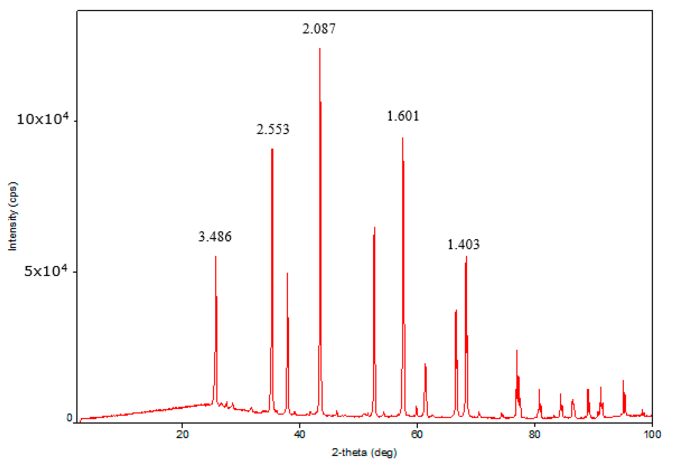
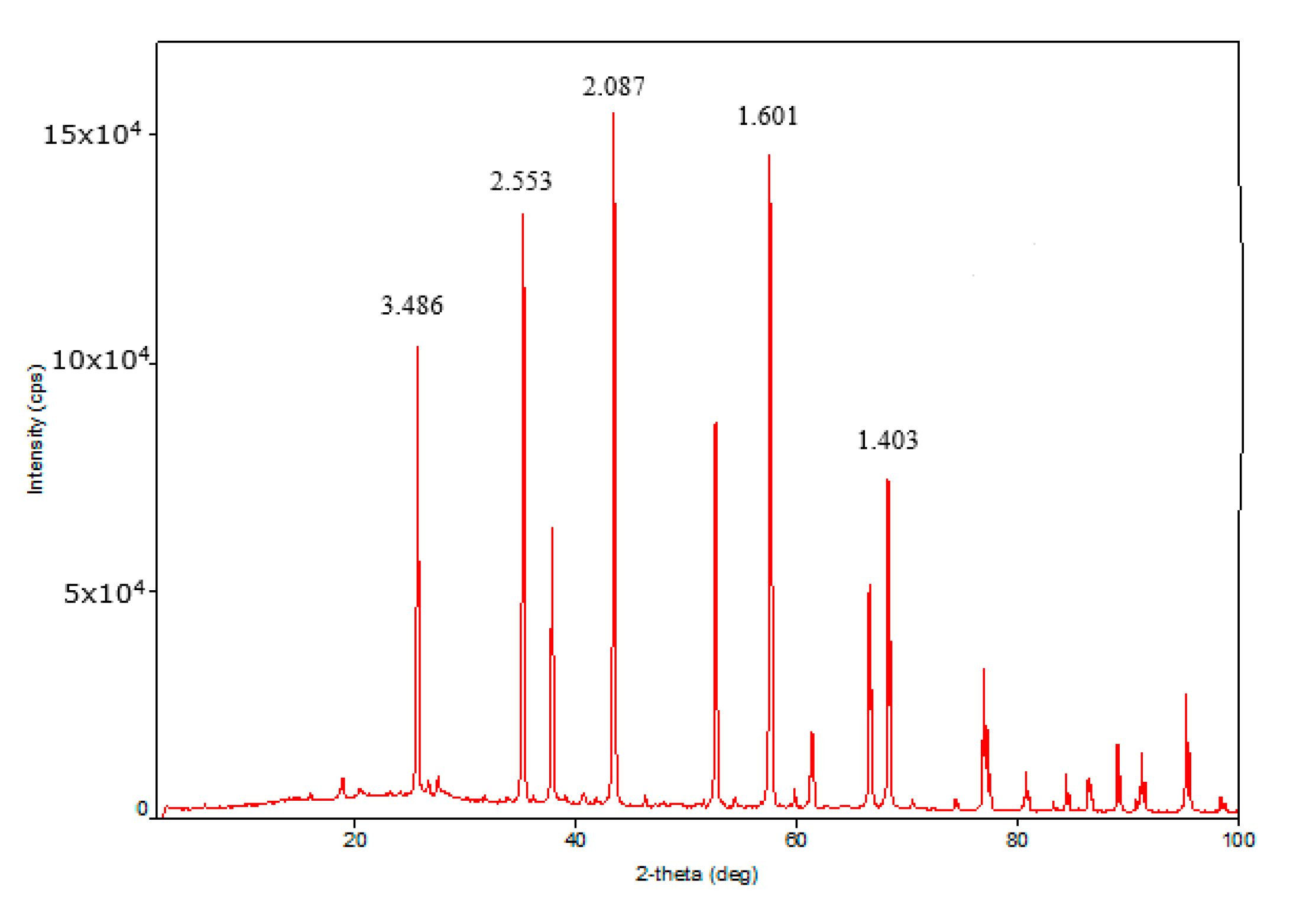
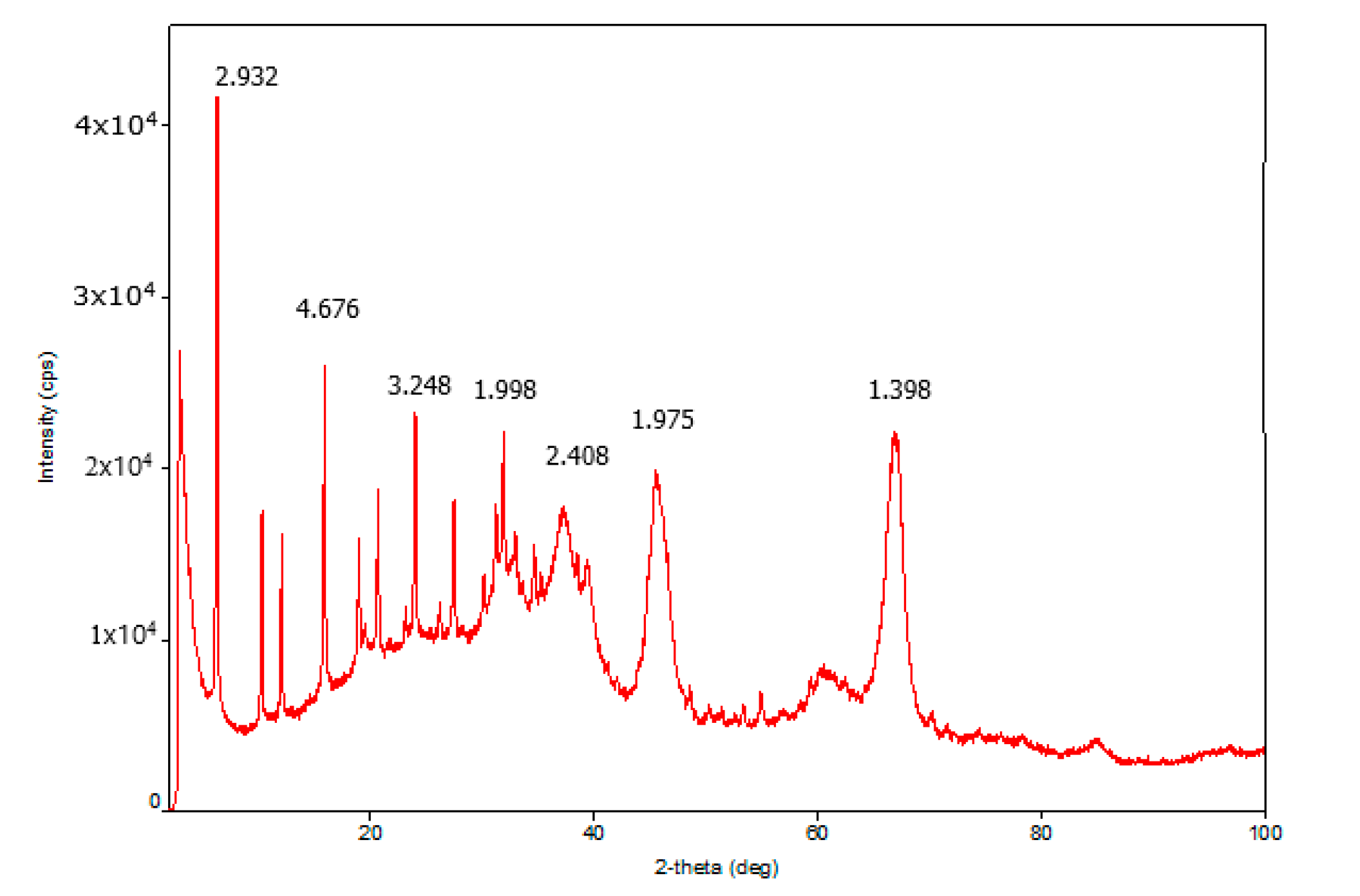
2.1. X-ray Diffraction Analysis

X-ray diffraction (XRD) analysis of the traditional granular catalyst showed the presence of γ-Al2O3 and zeolite Y in the sample. The XRD patterns of γ-Al2O3 and zeolite Y were characterized by 2θ = 2.932, 4.6761, 3.2482, 1.998 and 2.402, 1.975, 1.398 diffraction peaks. The medium coherent-scattering regions of γ-Al2O3 according to planes (440), (400), and (311) conforming to more intensive reflexes were 14.51, 16.20, and 22.77 Å. The coherent-scattering regions of zeolite Y according to planes (111), (220), (331), and (622) were 47.59, 43.08, 45.53, and 88.59 Å. XRD analysis of the highly porous support and the highly porous catalyst which is the highly porous catalyst with supported active components was conducted. The highly porous support, which was synthesized by template synthesis by high-temperature treatment of urethane foam matrix with pseudoboehmite at 1400 °C, was α-Al2O3 with specific high-intensity peaks 2θ = 3.5061, 3.4906, 3.2419, 3.1352, and 2.659. The coherent-scattering regions were 43.16, 61.02, 42.47, 60.12, and 44.61 Å. The XRD patterns of the highly porous catalyst were almost equal to the XRD patterns of the highly porous support because the bulk of the catalyst consisted of high-temperature modified α-Al2O3 (Figure 1, Figure 2 and Figure 3). The intensity of γ-Al2O3 and zeolite Y peaks was very low owing to their low quantity in the catalyst.

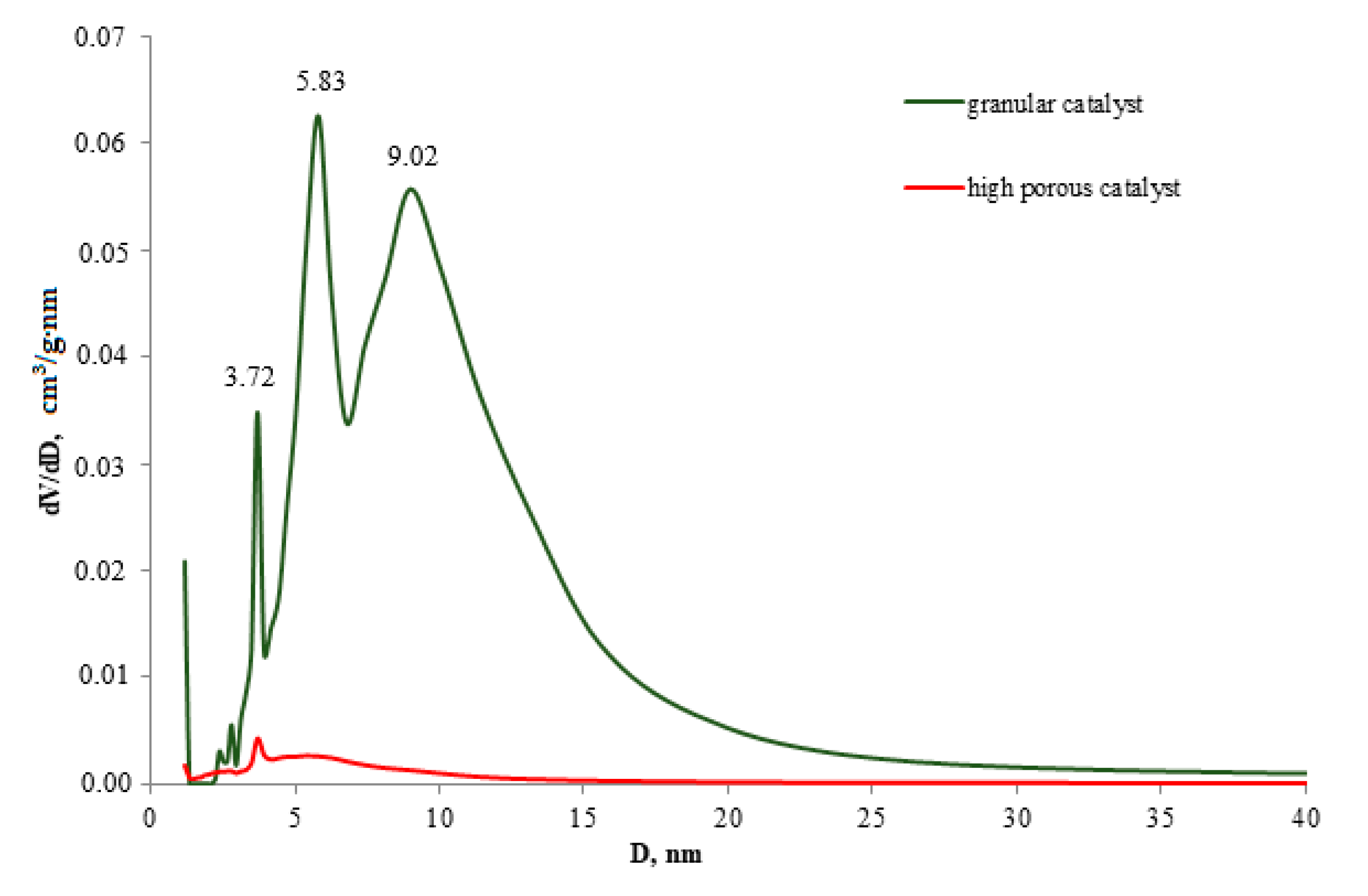
2.2. Textural Characteristics

The traditional catalyst was characterized by the presence of three peaks on the distribution curves to diameters at 3.71, 5.83, and 9.02. The surface area was 270 m2/g and the total pore volume was 0.6 cm3/g. The proportion of pores with d <5 nm in total pore volume was 9%. The loading of medium (5–10 nm) and large (>10 nm) pores was 47% and 44%, respectively. The high-temperature highly porous cellular material (α-Al2O3-HPCM) support was characterized by the absence of pores in the range of 0–300 nm (Table 1), which was available for determination by the low-temperature N2 adsorption method. This was due to the presence of the only high-temperature α-Al2O3 phase according to the XRD analysis data.
The differential pore diameter distribution curve of the highly porous catalyst with supported active components (Table 1, Figure 4) shows a low-intensity peak at 3.71 nm and wide halo without a strongly pronounced peak in the 4.45–15.5 nm range. In this case, the highly porous catalyst was characterized by a small quantity of pores in the range of <10 nm compared to the granular catalyst due to the significant contribution of the high-temperature phase α-Al2O3 of the highly porous support.
Despite the fact that the high porous support and high porous catalyst do not have pores with a diameter of 0–300 nm according to the low-temperature N2 adsorption, but these materials are characterized the presence of the large transport cells (pores) with 1500–2000 μ, providing the high heat and mass transfer.

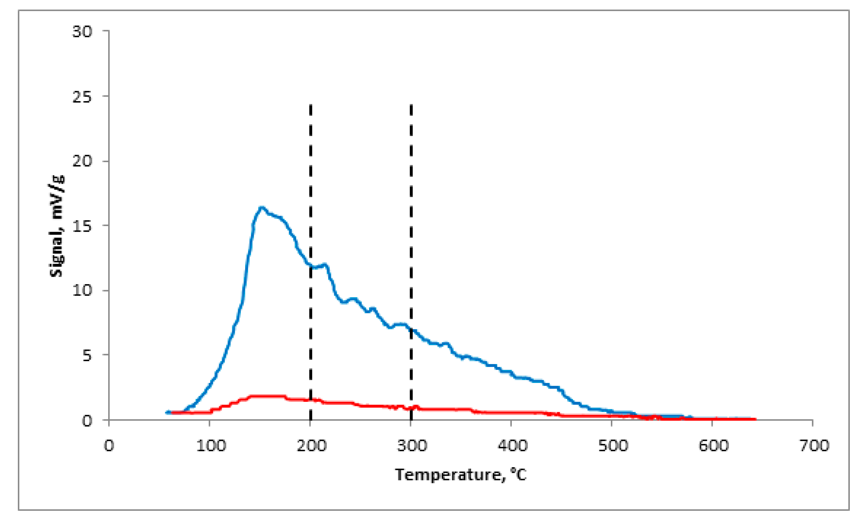
2.3. Concentrations of Acid Centers

The concentration of Bronsted and Lewis centers was determined by the NH3–TPD method. The NH3–TPD curves of the traditional catalyst demonstrated one maximum peak at 180 °C with spread to the high-temperature area. The breakdown of this spectrum according to weak (T < 200 °C), medium (200–300 °C), and high (T > 300 °C) temperature areas showed that the proportion of weak centers was 40.1% (130.1 mkmol/g) of the total amount, and those of medium and strong acid centers were 39.4% (127.9 mkmol/g) and 28.5% (92.5 mkmol/g), respectively.
For the α-Al2O3-HPCM support, the release of the molecular probe in the full range of the study samples was not observed in the NH3–TPD spectrum. The catalyst, which was synthesized based on α-Al2O3-HPCM, characterized the low summary concentration of the Lewis and Bronsted centers. Their quantity was 30 times smaller for the (γ-Al2O3-zeolite Y)/α-Al2O3-HPCM than that of the granular catalyst, and the low percentage of strong acid centers Td ≥ 300 °C able to initiate the cracking and carbon-producing reactions was noted (Figure 5, Table 2).

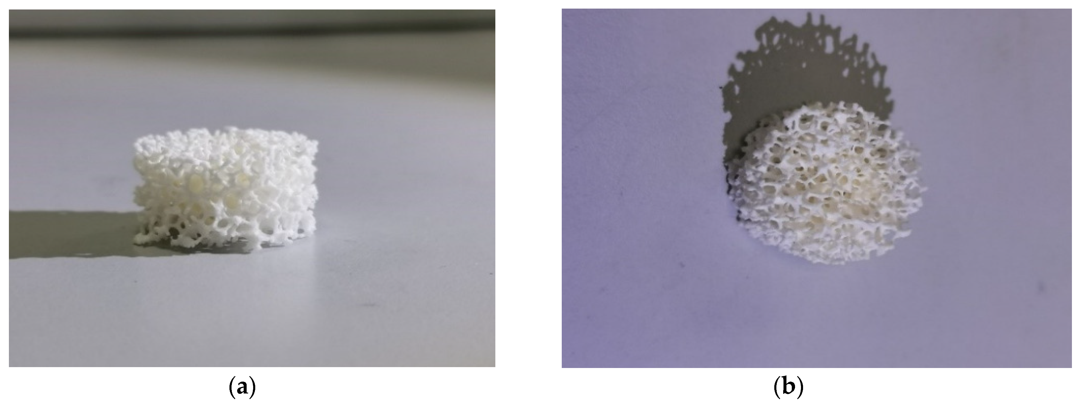
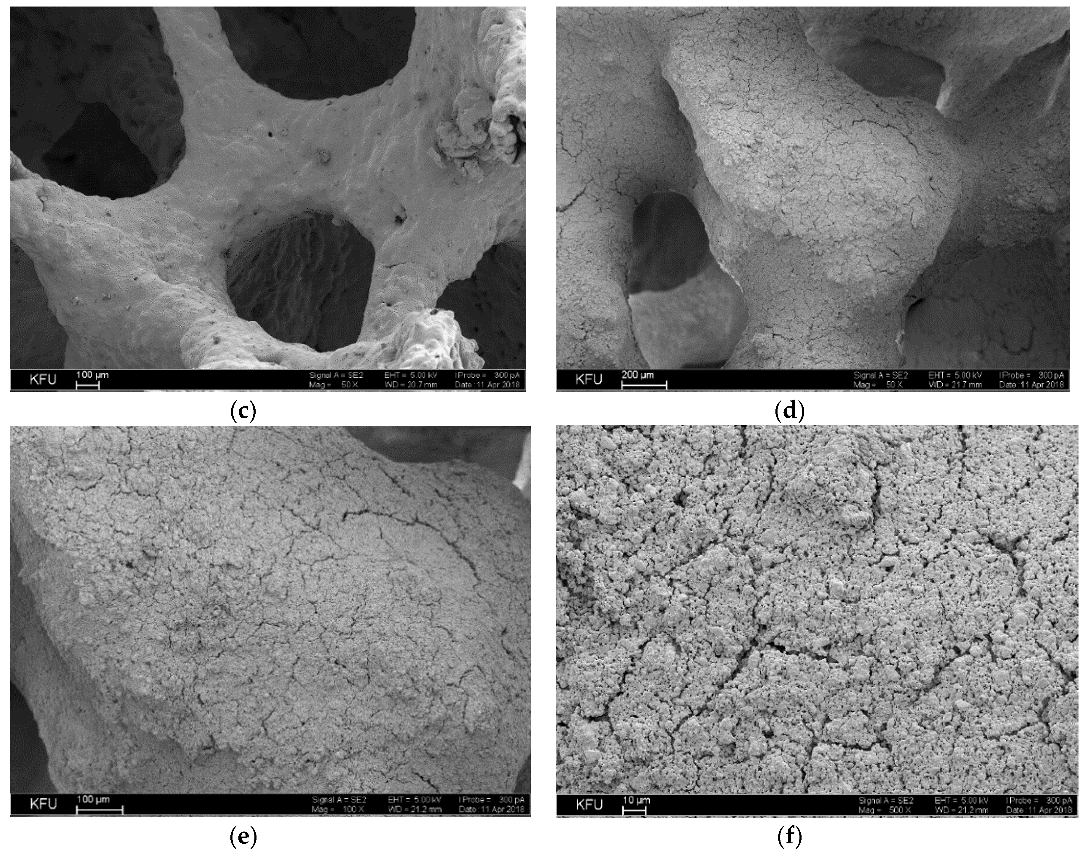
2.4. Surface Morphology of Highly Porous Catalyst

The surface morphology of the highly porous α-Al2O3-HPCM support and the secondary active component layer of the highly porous catalyst was determined by SEM.
The alumina surface morphology analysis of the highly porous support (Figure 6a–c) and highly porous catalyst (Figure 6d–f) was performed by SEM. The bridge surface of the native highly porous support featured a variety of protrusions and recesses, and different impurities. Further application of the active components led to a uniform active component formation, which under sintering, resulted in different agglomerate forms (Figure 6). The cell (pore)sizes were 1500–2000 μ.

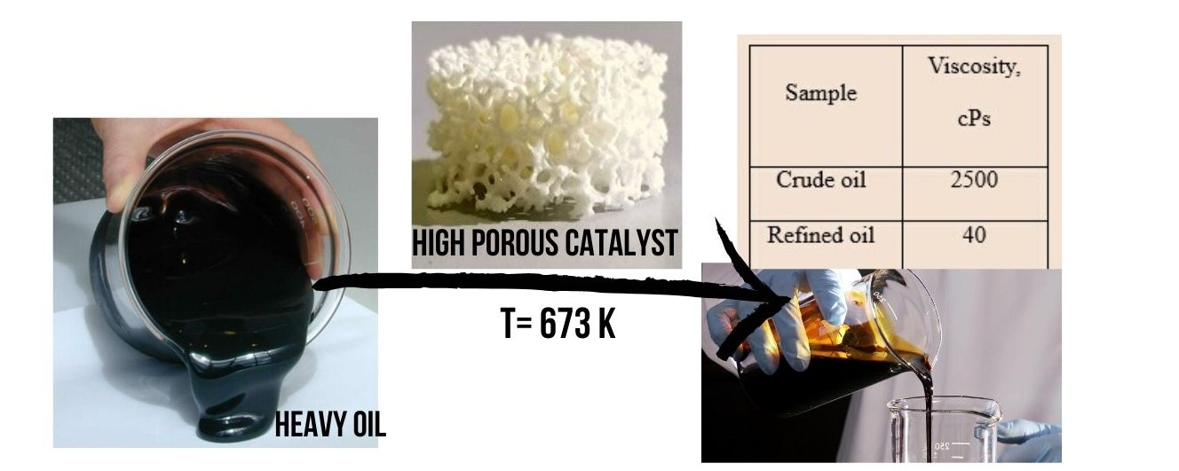
2.5. Performance Features

Catalytic tests were conducted in the process of decreasing oil viscosity. A thermal process replacing the catalyst with quartz was conducted for comparison. Catalytic test results show that the dynamic oil viscosity in thermal treatment at 400 °C in a reactor and at atmospheric pressure was reduced to 41 cPs (Table 3). The gas phase quantity was 185 mL/h. The major components were methane, ethane, and propane, in quantities of approximately 60.4, 17.8, and 10.1% vol., respectively (Table 4). Liquid adsorption chromatography showed the group composition of the thermally treated oil changes compared with the crude oil composition. An oil fraction increase of 10.05% (from 49.65–59.70% mass) due to a proportional resin fraction decrease of 10.71% (from 40.12–29.41% mass) was observed. In addition, a slight increase in asphaltene content of 0.5% was observed.
The process of decreasing oil viscosity in the presence of the traditional granular catalyst allowed a decrease in viscosity to 196 cPs. The quantity of generated gas phase was 285 mL/h. Liquid adsorption chromatography analysis of the catalytic treated oil also demonstrated the transformation of hydrocarbon groups (Table 5). There was an increase in oil fraction of 14.18% mass (from 49.65–63.83% mass) and an increase in asphaltenes of 2.63% mass, due to the decrease in resin content of 16.57% mass (from 40.12–23.55% mass).
The use of highly porous material with the active component coating as the catalyst resulted in a decrease in oil viscosity to 40 cPs. Moreover, it was found that the active phase quantity was only 1.25 g, seven times smaller than the granular catalyst quantity. The oil group composition analysis in the reactor output also showed an oil fraction increase of 16.89% (from 49.65–66.54%) due to the decreased resin (Table 5). It should be noted that a significantly lower rate (137 mL/h) of the forming gas phase of the co-product was observed with the use of a highly porous catalyst.
In addition, an estimation of the cycle length of the work was conducted for the thermal and catalytic methods in the presence of the highly porous catalyst. The increased pressure in the reactor as the result of coke formation represents the completion rate of the process. The pressure increase of 4 kgp/sm2 in the thermal process differed throughout 16 h of the work. The reactor pressure of the process in the presence of the highly porous catalyst increased after 60 h of the work.

3. Experiment

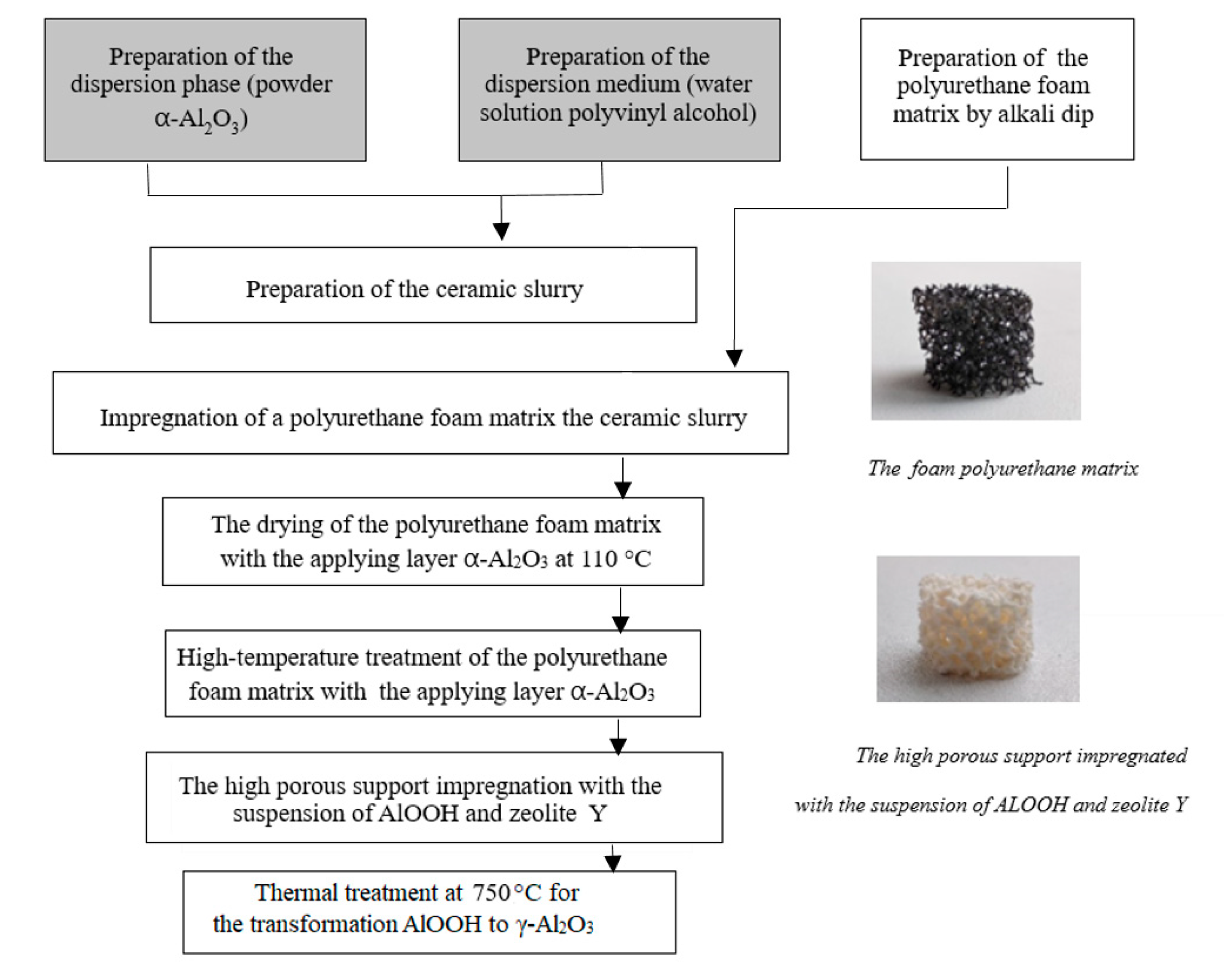
3.1. Catalyst Preparation

Aluminum hydroxide of pseudoboehmite morphology and zeolite Y were used to make the traditional granular catalyst. Zeolite Y powder was mixed with pseudoboehmite aqueous suspension to made a homogeneous paste, which was squeezed to obtain cylindrical extrudates with a diameter of 3 mm. The extrudates were dried at room temperature and at 110 °C for 24 h. Then the sample was calcined in stages at 450 °C for 4 h and 750 °C for 20 h. The zeolite content in the obtained catalyst was 15%.
The highly porous support was synthesized by template synthesis, which involves applying finely dispersed α-Al2O3 phase in aqueous media of polyvinyl alcohol on reticulated foam-celled foamed polyurethane. First, alkali dip was performed to form high surface defects on the foam polyurethane (Figure 7). Then the excess ceramic slurry was removed by pressing out the sample to the weight specified. Next the foam polyurethane matrix with the support layer of aluminum hydroxide was sequentially dried at 110 °C and subjected to annealing at 1400 °C to remove the foam polyurethane matrix and the robust α-Al2O3 scaffold formation. The catalyst was synthesized by impregnation of the highly porous support, which consisted of 15% zeolite Y and 85% pseudoboehmite. For this purpose, a suspension of boehmite and zeolite was applied on the highly porous support. The sample was dried for 1 h at room temperature and 24 h at 110 °C, with further calcination at 450 °C and 750 °C to form an additional robust scaffold and transfer from a hydroxide to an oxide.

3.2. Characterization of Experimental Samples

The phase composition of the catalyst was studied by x-ray powder diffraction (XRPD) on a MiniFlex 600 diffractometer (Rigaku, Japan) equipped with a D/teX Ultra detector with Cu Kα radiation (40 kV, 15 mA) in a range from 2–100° with a step of 0.05°.
The specific surface area and pore volume were measured by low-temperature nitrogen adsorption on an Autosorb-iQ-MP (Quantachrome, FL, USA), based on the accepted surface area of nitrogen molecules taken as 0.162 nm2. Nitrogen adsorption isotherms were obtained at –196 °C after degassing the sample at 300 °C to a residual pressure of 0.013 Pa. The pore volume and pore size distribution were calculated from the desorption branch of the isotherm, using the standard Barrett–Joyner–Highland procedure.
The acidic center concentration was determined by the thermoprogrammed desorption of ammonia (NH3–TPD) method using an AutoChem 2950 HP (Micromeritics, Norcross, GA, USA) analyzer. For this purpose, a sample of 0.5 g was loaded into the quartz reactor, followed by degassing of the instrument in an electric furnace at 550 °C; the heating rate was 10 °C/min and the carrier gas flow rate (He) was 10 mL/min. The support was saturated with a mixture of 10% NH3 in He at room temperature for an hour. Following that, the sample was purged with argon at 100 °C to remove the physically adsorbed ammonia.
SEM analysis of the formed alumina coating of the highly porous support and the supported active components was conducted on an EVO 50 XVP (Carl Zeiss, Germany) equipped with an INCA energy—350 (Oxford Instruments, Oxfordshire, UK) dispersion spectrometer. The resolution of the spectrometer was 130 eV. The analysis was performed at an accelerating voltage of 20 keV and a working length of 8 mm.
The kinematic oil viscosity of the crude and refined oil was determined on a Brookfield DV2T analyzer (AMETEK Brookfield, USA).
The hydrocarbon composition of the gas phase of the reaction products was found by gas chromatography on a Chromos GC-1000 (Chromos, Russia) with a flame ionization detector. A Valco PLOT VP-Alumina KCl capillary column (VICI Metronics, USA) with a length of 50 m and an alumina phase of 10 μ was used.
The group composition of the crude and refined oil was determined by liquid adsorption chromatography (LC) on alumina with the release of the hydrocarbon part and two groups of benzene and alcohol benzene resins. At the beginning of the adsorption separation, asphaltenes were pre-precipitated using a standard procedure in 40 times the amount of hexane.

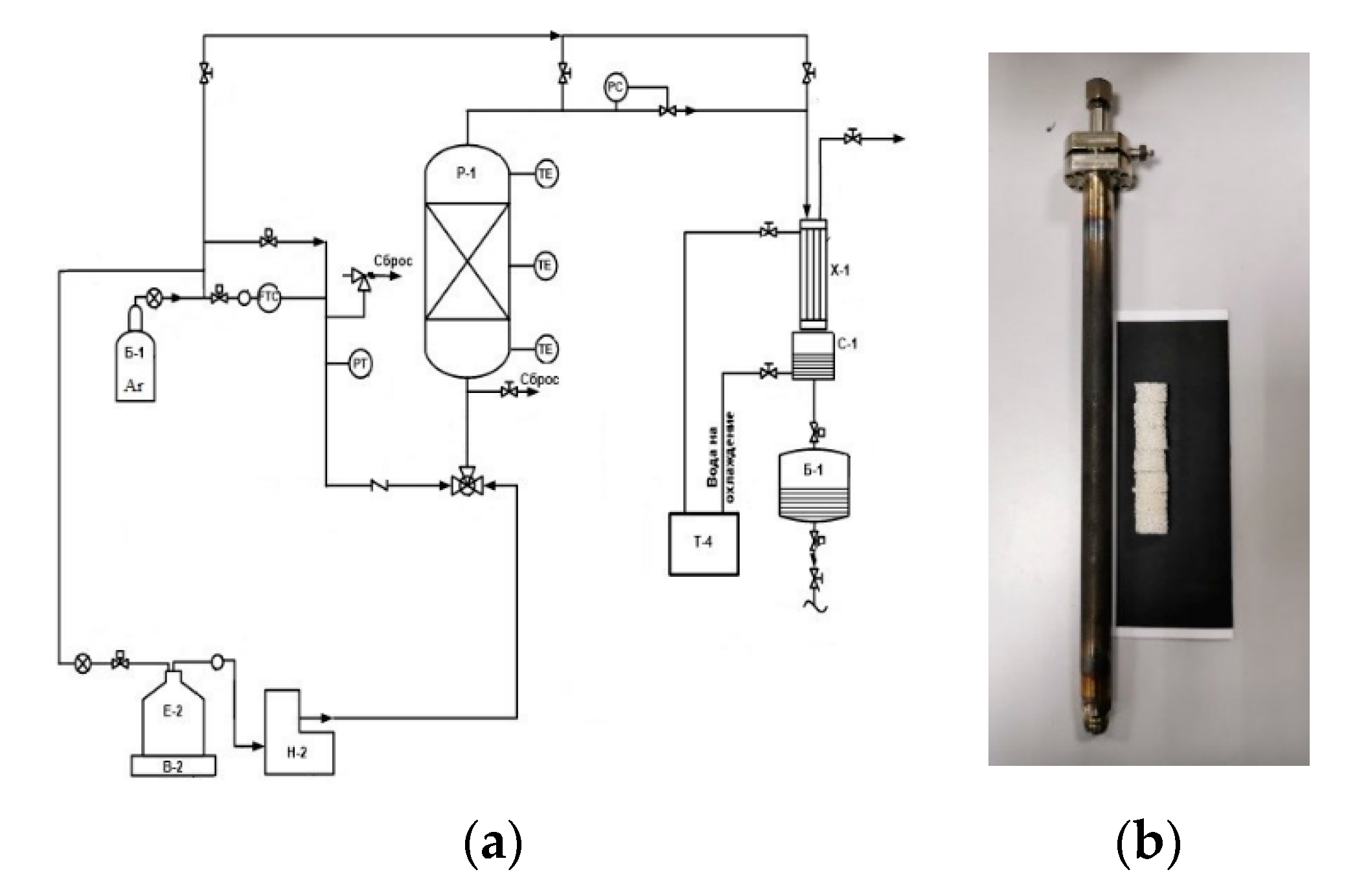
3.3. Heavy Oil Viscosity Reduction Tests

The experiments on decreasing oil viscosity were conducted with dehydrated crude oil with a dynamic viscosity of 2500 cPs (20 °C).
Thermal and catalytic processes of decreasing oil viscosity were conducted at the facility with an isothermal flow reactor (Figure 8) at 400 °C and 1 kgp/sm2, and the delivery rate was 20 mL/h. The reactor was loaded with quartz during the tests.
The value of the catalyst loading was 10.5 cm3, which is equivalent to 8.7 g if using the granular catalyst. The same value of the catalyst loading (10.5 cm3) in the case of the highly porous catalyst’s use confirmed the weight 1.25 g. This value is seven times smaller than if using the granular catalyst loading. The delivery rate was the same in both the granular and the highly porous catalyst, 20 mL/h (19.23 g/h, ρ20 = 0.9617 g/cm3). The specific oil feed speed (υoil) from the ratio of the oil feed speed (Voil) 19.23 g/h to the catalyst loading mass (mcat) showed the specific feed speed (υoil) of the granular catalyst was 2.2 h−1oil = Voil/mcat = 19.23/8.7) and that of the highly porous catalyst was 15.4 h−1 (υ = 19.23/1.25).
The loading weight of the traditional granular catalyst in the reactor during the tests of decreasing oil viscosity was 8.7 g. The loading weight of the highly porous catalyst was 1.25 g.
The catalytic process of decreasing oil viscosity with heterogeneous acid catalysts was conducted at 350–400 °C under atmospheric pressure, with a weight ratio of catalyst to feed of 2.3:1 for the granular catalyst and 16:1 for the highly porous catalyst.

4. Conclusions

In this investigation, highly porous α-Al2O3-HPCM support was obtained by template synthesis. The method was based on the application of aluminum hydroxide suspension on a highly porous foamed polyurethane matrix with further high-temperature treatment at 1400 °C. According to SEM and XRD analysis, the highly porous structure of α-Al2O3 was formed. The arm thickness of the α-Al2O3-HPCM was 250–500 nm, and the surface had a rough morphology with different protrusions and depressions. The α-Al2O3 formed with highly porous support was characterized by the absence of pores with a diameter of less than 300 nm. Such pores can lead to diffusion limitation relative to the activity reduction in the cracking process of large resins and asphaltene molecules. In addition, according to NH3-TPD analysis α-Al2O3-HPCM was characterized by the absence of Lewis and Bronsted centers. These strong acid centers can initiate secondary reaction behavior of cracking with formation of coke and light hydrocarbons.
The prepared highly porous structure was used as support for the fixation of the secondary active component layer of α-Al2O3 and zeolite Y. According to the SEM analysis data, the highly porous (γ-Al2O3+zeolite Y)/α-Al2O3-HPCM catalyst was characterized by uniform distribution of the active phase α-Al2O3 and zeolite Y on the arms of the α-Al2O3-HPCM surface. The thickness of the secondary support (γ-Al2O3+zeolite Y) was 25–30 μ. The use of highly porous α-Al2O3-HPCM as the support, according to low-temperature adsorption N2 and NH3-TPD, provided a negligible quantity of pores with a diameter of less than 300 nm and the Lewis and Bronsted acid centers compared to the granular catalyst. The macro-pores (1500–2000 μ) of the highly porous α-Al2O3-HPCM support provided higher activity for the (γ-Al2O3-zeolite Y)/α-Al2O3-HPCM in the oil viscosity decrease (from 2500–40 cPs) because of a decrease in resin content and an increase in oil fraction content. The low amount of acid centers provided the low gas generation rate of the co-products (137 mL/h). The granular catalyst provided lower activity in the oil viscosity decrease (from 2500–196 cPs) and high gas phase rate (285 mL/h).
Also, the large transport pores and the thin secondary layer of the active components prolonged the cycle length of the highly porous catalyst’s work, which was four times longer than the thermal process. Thus, in accordance with the conducted research, it is expected that the obtained catalysts are a potential material for further improvement and use in the process of decreasing oil viscosity in situ at oil fields.

Author Contributions

A.K. performed experiments; G.V. wrote the original draft and visualization; A.L. (Artem Laskin) designed the experiments; I.I. wrote the conceptualization, review & editing, A.L. (Alexander Lamberov)—project administration. All authors have read and agreed to the published version of the manuscript.

Funding

The work was performed at the expense of subsidies allocated within the state support of the Kazan (Volga Region) Federal University in order to increase its competitiveness among the world’s leading scientific and educational centers.

Conflicts of Interest

The authors declare no conflict of interest.

References

  1. Taheri-Shakib, J.; Shekarifard, A.; Naderi, H. Heavy crude oil upgrading using nanoparticles by applying electromagnetic technique. Fuel 2018, 232, 704–711. [Google Scholar] [CrossRef]
  2. Carrillo, J.A.; Corredor, L.M. Upgrading of heavy crude oils: Castilla. Fuel Process. Technol. 2013, 109, 156–162. [Google Scholar] [CrossRef]
  3. Castañeda, L.C.; Muñoz, J.A.D.; Ancheyta, J. Combined process schemes for upgrading of heavy petroleum. Fuel 2012, 100, 110–127. [Google Scholar] [CrossRef]
  4. Kondoh, H.; Tanaka, K.; Nakasaka, Y.; Tago, T.; Masuda, T. Catalytic cracking of heavy oil over TiO2–ZrO2 catalysts under superheated steam conditions. Fuel 2016, 167, 288–294. [Google Scholar] [CrossRef]
  5. Stratiev, D.; Shishkova, I.; Dinkov, R.; Nikolova, R.; Mitkova, M.; Stanulov, K.; Sharpe, R.; Russell, C.A.; Obryvalina, A.; Telyashev, R.; et al. Reactivity and stability of vacuum residual oils in their thermal conversion. Fuel 2014, 123, 133–142. [Google Scholar] [CrossRef]
  6. Becker, P.J.; Serrand, N.; Celse, B.; Guillaume, D.; Dulot, H. Comparing hydrocracking models: Continuous lumping vs. single events. Fuel 2016, 165, 306–315. [Google Scholar] [CrossRef]
  7. Khalil, U.; Muraza, O.; Kondoh, H.; Watanabe, G.; Nakasaka, Y.; Al-Amer, A.; Masuda, T. Robust surface-modified Beta zeolite for selective production of lighter fuels by steam-assisted catalytic cracking from heavy oil. Fuel 2016, 168, 61–67. [Google Scholar] [CrossRef]
  8. Zhao, L.; Gao, J.; Xu, C.; Shen, B. Alkali-treatment of ZSM-5 zeolites with different SiO2/Al2O3 ratios and light olefin production by heavy oil cracking. Fuel Process. Technol. 2011, 92, 414–420. [Google Scholar] [CrossRef]
  9. Dik, P.P.; Danilova, I.G.; Golubev, I.S.; Kazakov, M.O.; Nadeina, K.A.; Budukva, S.V.; Pereyma, V.Y.; Klimov, O.V.; Prosvirin, I.P.; Gerasimov, E.Y.; et al. Hydrocracking of vacuum gas oil over NiMo/zeolite-Al2O3: Influence of zeolite properties. Fuel 2019, 237, 178–190. [Google Scholar] [CrossRef]
  10. Decolatti, H.P.; Dalla Costa, B.O.; Querini, C.A. Dehydration of glycerol to acrolein using H-ZSM5 zeolite modified by alkali treatment with NaOH. Microporous Mesoporous Mater. 2015, 204, 180–189. [Google Scholar] [CrossRef]
  11. Awayssa, O.; Al-Yassir, N.; Aitani, A.; Al-Khattaf, S. Modified HZSM-5 as FCC additive for enhancing light olefins yield from catalytic cracking of VGO. Appl. Catal. A Gen. 2014, 477, 172–183. [Google Scholar] [CrossRef]
  12. Lai, S.; She, Y.; Zhan, W.; Guo, Y.; Guo, Y.; Wang, L.; Lu, G. Performance of Fe-ZSM-5 for selective catalytic reduction of NOx with NH3: Effect of the atmosphere during the preparation of catalysts. J. Mol. Catal. A Chem. 2016, 424, 232–240. [Google Scholar] [CrossRef]
  13. Han, M.J.; Jiao, Y.L.; Zhou, C.H.; Guo, Y.L.; Guo, Y.; Lu, G.Z.; Wang, L.; Zhan, W.C. Catalytic activity of Cu–SSZ-13 prepared with different methods for NH 3-SCR reaction. Rare Met. 2019, 38, 210–220. [Google Scholar] [CrossRef]
  14. Grecco, S.T.F.; de Carvalho, D.R.; Zandonai, C.H.; Fernandes-Machado, N.R.C.; Lião, L.M.; Urquieta-González, E.A.; do Carmo Rangel, M. Catalytic cracking of crude soybean oil on Beta nanozeolites. J. Mol. Catal. A Chem. 2016, 422, 89–102. [Google Scholar] [CrossRef]
  15. Khalil, U.; Muraza, O.; Kondoh, H.; Watanabe, G.; Nakasaka, Y.; Al-Amer, A.; Masuda, T. Production of lighter hydrocarbons by steam-assisted catalytic cracking of heavy oil over silane-treated Beta zeolite. Energy Fuels 2016, 30, 1304–1309. [Google Scholar] [CrossRef]
  16. Zhou, J.; Teng, J.; Ren, L.; Wang, Y.; Liu, Z.; Liu, W.; Yang, W.; Xie, Z. Full-crystalline hierarchical monolithic ZSM-5 zeolites as superiorly active and long-lived practical catalysts in methanol-to-hydrocarbons reaction. J. Catal. 2016, 340, 166–176. [Google Scholar] [CrossRef]
  17. Liu, S.; Ren, J.; Zhu, S.; Zhang, H.; Lv, E.; Xu, J.; Li, Y.W. Synthesis and characterization of the Fe-substituted ZSM-22 zeolite catalyst with high n-dodecane isomerization performance. J. Catal. 2015, 330, 485–496. [Google Scholar] [CrossRef]
  18. Zhang, Y.; Zhou, K.; Zhang, L.; Wu, H.; Guo, J. Synthesis of mesoporous γ-Al2O3 by using cellulose nanofiber as template for hydrodesulfurization of dibenzothiophene. Fuel 2019, 253, 431–440. [Google Scholar] [CrossRef]
  19. Parkhomchuk, E.V.; Sashkina, K.A.; Semekina, V.S.; Okunev, A.G.; Lavrenov, A.V.; Likholobov, V.A. The Catalyst for the Heavy Oil Refinery. Russia Patent No. 2,506,997, 22 April 2014. [Google Scholar]
Figure 1. XRD pattern of granular catalyst.
Catalysts 10 00250 g001
Figure 2. XRD pattern of highly porous support.
Catalysts 10 00250 g002
Figure 3. XRD pattern of highly porous catalyst.
Catalysts 10 00250 g003
Figure 4. Differential curves of pore volume distribution.
Catalysts 10 00250 g004
Figure 5. NH3–TPD curves: blue: granular catalyst; red: highly porous catalyst.
Catalysts 10 00250 g005
Figure 6. (a,b) Images of highly porous α-Al2O3-HPCM support; (c) SEM image of highly porous support surface; (df) SEM images of highly porous catalyst.
Catalysts 10 00250 g006aCatalysts 10 00250 g006b
Figure 7. Synthesis of highly porous cellular material (α-Al2O3-HPCM) support and (γ-Al2O3-zeolite Y)/α-Al2O3-HPCM.
Catalysts 10 00250 g007
Figure 8. (a) Installation diagram of decreasing oil viscosity; (b) reactor and highly porous catalyst.
Catalysts 10 00250 g008
Table 1. Textural characteristics of samples.
SampleSBET (m2/g)/Vpore (cm3/g)Distribution SBET (m2/g) и Vpore (cm3/g) and Their Proportion (%) Accruing to Pore Diameter (nm)
< 55–10> 10
m2/g%m2/g/%m2/g/%
cm3/gcm3/gcm3/g
Granular catalyst270/62.23/23/147.3/55/60.47/22/
0.5950.05490.279470.26244
Highly porous support0.74/------
0.001------
Highly porous catalyst15.1/8.8746/59/5.0533/33/1.1721/8/
0.02410.00755310.00963400.0069329
Table 2. Concentration of acid centers of catalyst samples according to NH3-TPD.
SampleNtota.c., mkmol/gNк.ц., mkmol/g (%)
WeakMediumStrong
Td < 200 °C200 ≤ Td < 300 °CTd ≥ 300 °C
Granular catalyst324.5130.1 (40.1)127.9 (39.4)92.5 (28.5)
Highly porous support0000
Highly porous catalyst11.14.2 (37.8)3.2 (28.5)3.7 (33.7)
Table 3. Performance features of non-catalytic and catalytic processes for the oil viscosity decrease.
SampleTemperature (°C)Oil Feed Rate (mL/h)Viscosity (cPs)Amount of Gas Phase (mL/h)
Crude oil 2500
Thermal method
Refined oil4001541185
Catalytic method in the presence of granular catalyst
Refined oil40020196285
Catalytic method in the presence of highly porous catalyst
Refined oil4002040137
Table 4. Hydrocarbon components content (% vol.) in gas phase of oil refining processes.
ComponentThermal MethodCatalytic Method in the Presence of High Porous Catalyst
Methane60.4257.68
Ethane17.7516.23
Propane10.017.53
Propene1.470.09
Isobutane0.6912.60
Trans-2-butene2.370.33
1-butene2.782.20
Cis-2 butene0.410.27
Isopentane1.300.88
Pentane1.380.66
Butadiene-1,30.510.24
∑C60.511.01
∑C70.400.28
Table 5. Data of the group composition of crude and refined oil according to liquid adsorption chromatography analysis.
SampleGroup Composition (% Mass)
OilsResinsAsphaltenes
BenzeneAlcohol BenzeneAmountPure AcidsAsphaltenic AcidsAmount
Crude oil49.6527.2212.940.125.344.8910.23
Thermal method
Refined oil59.720.488.9329.415.525.3110.83
Catalytic method in the presence of the granular catalyst
Refined oil63.8316.267.2923.556.156.5312.86
Catalytic method in the presence of highly porous (γ-Al2O3+zeolite Y)/α-Al2O3-HPCM catalyst
Refined oil66.5413.979.2423.213.886.3710.25

