Article

Solar-Driven Chemical Looping Methane Reforming Using ZnO Oxygen Carrier for Syngas and Zn Production in a Cavity-Type Solar Reactor

by
Srirat Chuayboon
1 and
Stéphane Abanades
2,*
1
Department of Mechanical Engineering, King Mongkut’s Institute of Technology Ladkrabang, Prince of Chumphon Campus, Chumphon 86160, Thailand
2
Processes, Materials and Solar Energy Laboratory, PROMES-CNRS, 7 Rue du Four Solaire, 66120 Font-Romeu, France
*
Author to whom correspondence should be addressed.
Catalysts 2020, 10(11), 1356; https://doi.org/10.3390/catal10111356
Submission received: 22 October 2020 / Revised: 13 November 2020 / Accepted: 17 November 2020 / Published: 21 November 2020
(This article belongs to the Special Issue Chemical Looping for Catalysis)

Abstract

:
Converting sunlight into chemical fuels and metal commodities, via solar thermochemical conversion processes, is an attractive prospect for the long-term storage of renewable energy. In this study, the combined methane reforming and ZnO reduction in a single reaction for co-production of hydrogen-rich syngas and metallic Zn was demonstrated in a flexible solar thermochemical reactor prototype, driven by highly concentrated sunlight. Using solar energy as the process heat source in chemical-looping methane reforming with the ZnO/Zn oxygen carrier is a means to reduce the dependence on conventional energy resources and to reduce emissions of CO2 and other pollutants, while upgrading the calorific value of the feedstock for the production of energy-intensive and high-value chemical fuels and materials. On-sun experiments were carried out with different operating parameters including operating temperatures (800–1000 °C), inlet methane flow-rates (0.1–0.4 NL/min), and inlet ZnO feeding-rates (0.5–1.0 g/min) both in batch and continuous modes under reduced (0.15 and 0.45 bar) and atmospheric pressures (0.90 bar), thereby demonstrating solar reactor flexibility and reliability. As a result, increasing the temperature promoted net ZnO conversion at the expense of favored methane cracking reaction, which can be lowered by decreasing pressure to vacuum conditions. Diminishing total pressure improved the net ZnO conversion but favored CO2 yield due to insufficient gas residence time. Rising ZnO feeding rate under a constant over-stoichiometric CH4/ZnO molar ratio of 1.5 enhanced ZnO and methane consumption rates, which promoted Zn and syngas yields. However, an excessively high ZnO feeding rate may be detrimental, as ZnO could accumulate when the ZnO feeding rate is higher than the ZnO consumption rate. In comparison, continuous operation demonstrated greater performance regarding higher ZnO conversion (XZnO) and lower methane cracking than batch operation. High-purity metallic Zn with a well-crystallized structure and of micrometric size was produced from both batch and continuous tests under vacuum and atmospheric pressures, demonstrating suitable reactor performance for the solar thermochemical methane-driven ZnO reduction process. The produced Zn metal can be further re-oxidized with H2O or CO2 in an exothermic reaction to produce pure H2 or CO by chemical-looping.

1. Introduction

Solar-driven thermochemical fuel production can be regarded as one of the best avenues to store solar energy in chemical forms. Various solar-driven thermochemical processes, such as gasification [1,2], chemical looping methane reforming [3,4], two-step H2O/CO2 splitting [5], methane cracking [6,7,8], and carbothermal and methanothermal metallurgy [9], have been largely proposed. Among them, methanothermal reduction of metal oxides (methane-driven reduction and reforming) is of particular interest. The ideal stoichiometric methane-driven reduction of metal oxides to syngas and metals can be written in Equation (1).
MxOy + yCH4 → xM + yCO + 2yH2
In this approach, methane (CH4) is employed as a reducer to both extract the oxygen from metal oxides and overcome the thermodynamic barrier [3], thereby producing both syngas and metals in a single reaction at moderate temperatures (depending on which metal oxides are employed). Metal oxides can be generally categorized into two groups. On the one hand, non-volatile oxides such as ceria (CeO2-δ) [4], iron oxides (Fe2O3/Fe3O4, ferrites) [9], and perovskites (e.g., La1−xSrxMnO3−δ) [10] remain in solid state throughout the cycle. Hence, only oxygen is discharged from their structures. Non-volatile oxides are commonly utilized as oxygen carriers in two-step H2O/CO2 splitting redox cycles [10] and chemical looping reforming [11,12]. Nonetheless, their weaknesses are associated with their physicochemical characteristics such as favored sintering with regard to iron oxides or non-stoichiometric reactions with regard to ceria or perovskites. On the other hand, volatile metal oxide reactions proceed via a solid-to-gas/liquid phase transition of the products (either gaseous (ZnO/Zn, MgO/Mg [13]) or liquid (SnO2/Sn) [14,15]) in the reduction step. The products evaporate/melt in the gas phase and then condense in the solid phase when temperature declines. Contrary to non-volatile oxides, volatile metal oxides display mainly high oxygen exchange capacity thanks to the complete phase transition. They can also be employed as oxygen carriers at the expense of an additional reactor required for the exothermal oxidation reaction. Nevertheless, volatile metal oxides have an adverse effect on a recombination issue which can be alleviated by gas quenching [16].
The ZnO/Zn redox pair has been proposed as an attractive candidate for solar thermochemical processes thanks to its beneficial physical and thermochemical properties. When ZnO is reduced with methane (methane-driven ZnO reduction), the reaction can take place at temperatures below 900 °C according to Equation (2).
ZnO(s) + CH4 → Zn(g) + CO + 2H2
(ΔH° = 444.9 kJ/mol, T@(ΔG0 = 0) = 837 °C)
While ZnO reacts with methane, side reactions involving Equations (3)–(11) are possible, which lead to the formation of by-products.
ZnO + C→Zn + CO
ZnO + CO→Zn + CO2
ZnO + H2→Zn + H2O
C + H2O→CO + H2
C + CO2↔2CO
CH4 + CO2→2CO + 2H2
CH4 + H2O→CO + 3H2
CO2 + H2↔CO + H2O
CH4→C + 2H2
The overall side reaction of ZnO reduction with methane that yields Zn, CO2, and H2O (summation of Equations (2), (4) and (5)) can be written in Equation (12).
4ZnO + CH4→4Zn + CO2 + 2H2O
ZnO conversion (XZnO) is defined as the net fraction of ZnO converted to Zn, which corresponds to Zn yield, and it is determined by an oxygen elemental balance according to Equation (13).
X Z n O   =   n C O   +   2 n C O 2   +   n H 2 O n Z n O
where ni are the mole amounts of species i.
Methane conversion (XCH4) is defined as the net fraction of methane converted to syngas, solid carbon, or soot, and it is determined according to Equation (14):
X C H 4   =   1 m ˙ u n r e a c t e d   C H 4 m ˙ C H 4
where X C H 4 is the methane conversion, m ˙ u n r e a c t e d   C H 4 is the mass flow-rate of unreacted methane in the off-gas, and m ˙ C H 4 is the mass flow-rate of injected methane.
Many advantages of solar methane-driven ZnO reduction can be underlined (and further extended to all chemical looping methane reforming processes in general): (1) both metallic Zn and syngas are produced in a single reaction at temperatures below 900–1000 °C, (2) a H2:CO ratio of 2:1 is possible, compatible with methanol production or Fischer–Tropsch for synthetic liquid fuels, (3) an excess of steam and addition of catalysts, which implies extra heat consumption and catalyst costs, are not required, (4) Zn product can be alternatively used as an oxygen carrier for a two-step H2O/CO2 splitting system.
In prior studies, ZnO reduction with methane was mostly investigated thermodynamically [17,18]. One of these studies [18] reported that CH4 + ZnO reaction was pretty complicated as a result of side reactions, and CH4 conversion and H2 yield were dependent on operating temperature. Besides, Steinfeld et al. [19] experimentally explored CH4 + ZnO reaction in a gas-particle vortex 5-kW reactor, yielding ZnO conversion up to 90%. In addition, Levêque and Abanades [20] found that conducting ZnO reduction under vacuum pressure improved reaction kinetics and reduced operating temperature, at the expense of additional energy requirement associated with vacuum pumping.
Solar-driven ZnO reactors can be classified according to the type of process operation regarding batch or continuous modes. On the one hand, packed-bed reactors are typically handled in a batch mode [21] and feature high reaction extent thanks to sufficient residence time [22]. Nevertheless, they often show an adverse effect related to high temperature gradient issues [21], which could possibly cause unreacted reactant remaining in the reactor [23]. Wieckert et al. [22] tested a 300 kWth two-cavity solar reactor for carbothermal reduction of ZnO and achieved 50 kg/h of 95%-purity Zn. On the other hand, moving-front [24], entrained particle flow [25], drop tube [26], gravity-fed [27], and vortex flow [19] reactors are often operated in a continuous mode. They feature fast conversion rates; however, heat and mass transfer and gas residence constraints must be taken into account [28]. For example, a vortex-flow solar reactor was experimented for continuous combined ZnO reduction and CH4 reforming, yielding 90% chemical conversion of ZnO in a single pass [19]. In fact, with continuous ZnO injection, ZnO feeding rate plays an important role on reaction performance; however, prior studies on ZnO feeding rate influence have not been reported. Actually, rising ZnO feeding rate is valuable for enhancing production rate. However, excessively high ZnO feeding rate can have an adverse effect yielding incomplete ZnO conversion. Prior study on ZnO reduction with methane has been carried out only in a batch mode to unravel the effect of the main operating conditions [29], and the development of a continuous process is challenging.
Therefore, this study aimed to experimentally investigate the on-sun methane reforming using solid ZnO (equivalent to methane-driven ZnO reduction) in both batch and continuous modes under vacuum and atmospheric pressures in a flexible solar reactor prototype. The cavity-type solar reactor was tested at different temperatures, pressures (reduced and atmospheric pressures), and ZnO feeding rates. A comparative study of methane-driven ZnO reduction between batch and continuous ZnO injection was performed.

2. Results and Discussion

2.1. Batch Operation

The impact of operating temperature on reaction performance was experimentally investigated under batch operation thanks to an easily controllable test under the considered conditions. Methane-driven reduction of ZnO was conducted isothermally at temperatures of 800, 900, and 1000 °C under atmospheric pressure (0.90 bar). A well-grinded packed-bed of ZnO (2 g) was loaded and uniformly spread in the cavity bottom with initial bed height in the range 1.8–2.2 mm (bulk density ~0.5–0.6 g/cm3), thus avoiding high thermal gradient across its height. A constant mixture of reactive CH4 (0.1 NL/min) and inert carrier N2 (0.2 NL/min), resulting in 33% inlet CH4 concentration, was fed. Figure 1 shows syngas yields, methane conversion (XCH4), and net ZnO conversion (XZnO) as a function of temperature. With temperature rising, a remarkable increase in the syngas yield, particularly H2, was observed. For instance, CO, CO2, and H2 increased from 0.87, 0.34, and 4.63 mmol/gZnO at 800 °C to 2.28, 1.12, and 14.34 mmol/gZnO at 1000 °C, resulting in H2/CO ratios from 5.32 at 800 °C to 6.29 at 1000 °C. A sharp increase in the H2 yield at 1000 °C was attributed to the side reaction associated with methane cracking (Equation (11)). In fact, H2O according to Equation (12) was also formed, but it could not be detected by on-line gas analysis. Besides, H2O yield can be calculated assuming that it doubles the CO2 yield according to Equation (12). Because of the strong methane cracking reaction at 1000 °C, XCH4 attained the maximum value as high as 47.0%. The methane cracking reaction at 1000 °C resulted in the carbon formation, which could adversely affect the performance of the process. Fortunately, this issue can be tackled by decreasing the operating temperature below 1000 °C. Carbon-atom balance (Equation (15)) was applied to determine solid carbon production yield.
(nCH4)inlet = (nC + nCO + nCO2 + nCH4)outlet
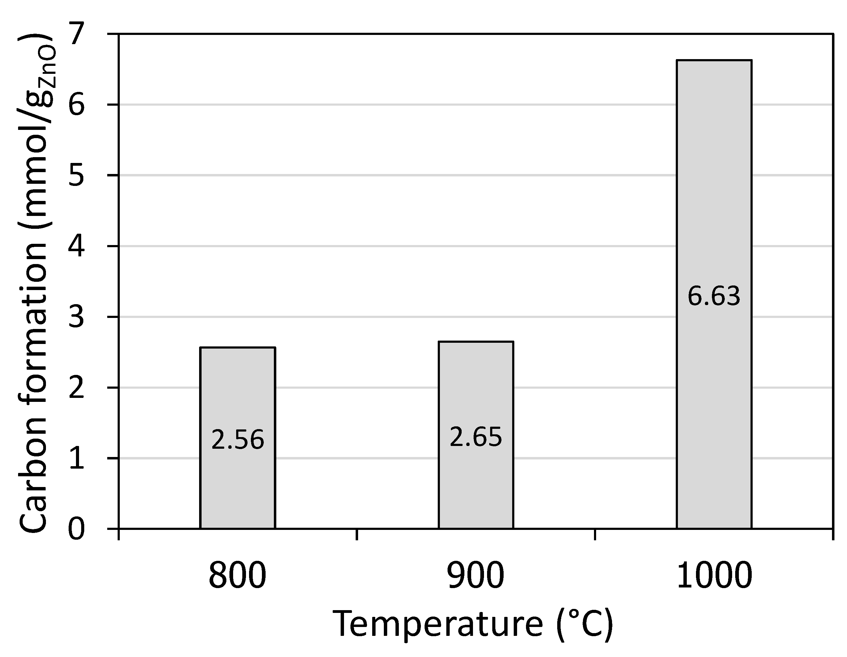
As expected, carbon formation rose considerably when increasing the temperature to 1000 °C. For instance, solid carbon formation increased from 2.56 mmol/gZnO at 800 °C to 6.63 mmol/gZnO at 1000 °C, according to Figure 2.
In addition, the maximum XZnO value of 54.8% was reached at 1000 °C. The incomplete ZnO conversion was ascribed to unreacted ZnO remaining in the cavity (also part diffusion in the insulation layer may be possible) and Zn recombination with CO, CO2, and H2O at the outlet cooling zone (inverse reactions of Equations (3)–(5)). In a nutshell, increasing temperature increased syngas yield, XCH4, and XZnO at the expense of favored thermal methane dissociation, especially at 1000 °C, which caused solid carbon deposition. For this reason, temperatures in the range of 900–950 °C were found most recommended for performing methane-driven ZnO reduction under atmospheric pressure.
Besides, the impact of total pressure on reaction performance was also studied since decreasing the total pressure theoretically favors the ZnO reduction reaction [20,29]. Experiments were carried out isothermally at reduced pressures (0.15 and 0.45 bar) and atmospheric pressure (0.90 bar) under batch operation. Thanks to the above reported results on the temperature influence, the temperature of 900 °C was chosen for this study in order to relieve the methane cracking issue. Similar to the temperature tests, a packed-bed of ZnO (2 g) was supplied, and 0.1 NL/min of methane flow rate was fed once the desired operating temperature was stable. Figure 3 shows that CO and H2 yields dropped with decreasing total pressure, from 2.04 and 7.03 mmol/gZnO at 0.90 bar to 0.92 and 3.31 mmol/gZnO at 0.15 bar, resulting in a H2/CO ratio from 3.44 at 0.90 bar compared to 3.60 at 0.15 bar. In contrast, a considerable increase in the CO2 yield when reducing the pressure was observed, from 0.89 mmol/gZnO at 0.90 bar to 1.49 mmol/gZnO at 0.15 bar. These variations can be attributed to the fact that as the pressure decreased, gas velocity increased (by a factor x6 when decreasing pressure from 0.90 to 0.15 bar), which led to a decrease in the gas residence time. Actually, decreasing pressure enhanced reduction extent (as reflected by the increase of XZnO) at the expense of decreased gas residence time. As a result, solid-gas reactions (Equations (2)–(7)), gas phase reactions (Equations (8)–(10)), and thermal methane dissociation (Equation (11)) were negatively affected (due to possible kinetic limitations), leading to decreased H2 and CO and increased CO2. The discharged oxygen from ZnO was, therefore, recovered rather in the form of CO2 than CO, thereby explaining the increase of both CO2 and XZnO. Since the oxygen supply remains identical because the same amount of ZnO is used in the tests at different pressures, the higher CO2 yield observed when decreasing pressure may be the result of kinetic limitations. CO2 is mainly formed via reaction of ZnO with CO (Equation (4)) and then the Boudouard equilibrium determines the CO and CO2 proportion. Thus, the main reason for higher CO2 yield is because the gas residence time is lowered when decreasing total pressure, which in turn limits the CO2 conversion via the Boudouard reaction (Equation (7)).
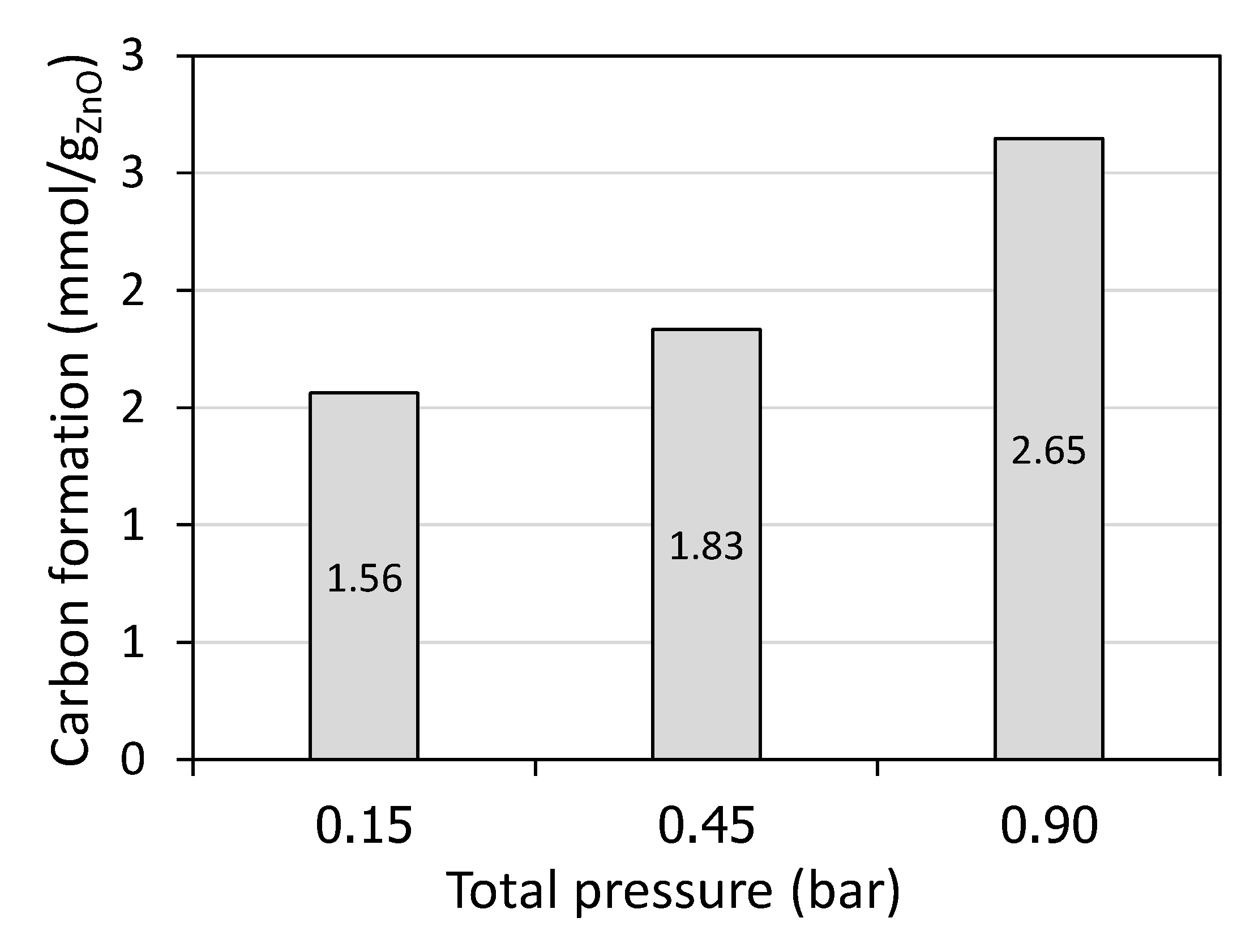
In addition, the drop in the XCH4 with a decrease in the total pressure also resulted from the increase of the gas velocity (gas residence time decrease), in agreement with the decline of solid carbon formation (from 2.65 mmol/gZnO at 0.90 bar to 1.56 mmol/gZnO at 0.15 bar according to Figure 4), thus pointing out the less favorable methane cracking reaction. Importantly, with diminishing the total pressure, XZnO was enhanced from 45.8% at 0.90 bar to 55.8% at 0.15 bar, revealing a positive impact of lowering the total pressure on net ZnO conversion, in agreement with both thermodynamics (production of Zn vapor and syngas is favored at low pressure [29]) and previous studies on vacuum MgO carbothermal reduction [30]. In short, decreasing the total pressure enhanced XZnO at the expense of lowered syngas yield but increased CO2 yield. In addition, continuous operation involving a vacuum may be costly in terms of energy penalty and capital investment. With respect to these results from batch tests, a temperature at 950 °C and a medium pressure at 0.45 bar are advocated to both favor syngas yield and ZnO conversion and alleviate the side methane cracking reaction.

2.2. Continuous Operation

Methane-driven ZnO reduction was also performed with continuous ZnO injection to study both the feasibility in operating this process in a continuous mode and the influence of ZnO feeding rate on reaction performance. Experiments were conducted isothermally under atmospheric pressure (0.90 bar), and the proper temperature of 950 °C was selected to alleviate the methane cracking issue. In each test, 10 g of ZnO powder was supplied, and a constant CH4/ZnO inlet molar ratio of 1.5 (50% of methane in excess) was fixed because the excess of reducer flow rate is necessary to favor ZnO conversion. The influence of ZnO feeding rates of 0.5 and 1.0 g/min was investigated. Figure 5 reveals that an increase in the ZnO feeding rate increased syngas yield. For example, CO, CO2, and H2 yields were 2.09, 0.94, and 5.95 mmol/gZnO at 0.5 g/min compared to 2.85, 1.23, and 8.17 mmol/gZnO at 1.0 g/min, resulting in the evolution of total syngas yield from 9.0 mmol/gZnO at 0.5 g/min to 12.3 mmol/gZnO at 1.0 g/min. Similarly, both XCH4 and XZnO conversion rose significantly from 11.1 and 47.5% at 0.5 g/min to 13.8 and 63.3% at 1.0 g/min, and solid carbon formation also increased from 0.83 mmol/gZnO at 0.5 g/min to 1.89 mmol/gZnO at 1.0 g/min. This implied that an increase in the ZnO feeding rate promoted ZnO and CH4 consumptions, leading to an enhancement in the evolved syngas, XCH4, and XZnO. However, rising excessively the ZnO feeding rate would be detrimental because ZnO feeding rate could exceed ZnO consumption rate, which may result in adverse reaction performance and eventually lead to ZnO accumulation. Therefore, the optimal ZnO feeding rate with respect to the maximum XZnO conversion need to be further investigated. In short, increasing ZnO feeding rate under a constant over-stoichiometric CH4/ZnO molar ratio promoted syngas yield, XZnO, as well as XCH4, thanks to increased ZnO and CH4 consumptions. With this solar reactor prototype, the feasibility of performing methane-driven ZnO reduction with continuous ZnO injection was established.

2.3. Comparison of Batch and Continuous Operation

Figure 6 shows the representative syngas production rates’ evolution together with reactor temperatures for both continuous (Figure 6a) and batch (Figure 6b) operation at 900 °C under atmospheric pressure (0.90 bar). In this study, a packed bed of ZnO (2 g mass) reacted with a constant methane flow-rate of 0.3 NL/min for the batch test, while ZnO powder (10 g mass) was fed at 1 g/min to react with a methane flow-rate of 0.4 NL/min, resulting in a CH4/ZnO molar ratio of 1.5, for the continuous test. During continuous operation, the syngas production rates fluctuated constantly and consistently for all the gas species, in response to a change in the reactor temperatures, caused by the varying solar power input resulting from clouds passage. This confirmed that temperature played an important role on the performance of ZnO reduction with methane. Note that only this experiment suffered from the cloud shadowing issue; however, the results can still be reliable and compared. During the initial period (0–5 min of duration), H2 specie was produced without the presence of CO and CO2 because of only CH4 cracking reaction (ZnO was not yet injected and remained in the screw feeder pathway at that time). After that, CO, CO2, and H2 were formed once ZnO was injected in the cavity zone, and they reached their maximum level at around 20 min duration. In fact, the theoretical operating time should be approximately in the range 10–15 min (with respect to ZnO mass fed at 1 g/min); however, the actual operating time was above 45 min because of inconstant ZnO feeding rate caused by temporal ZnO feeding blockage and mainly low reaction kinetics (at 900 °C) that cause temporal ZnO accumulation, especially during the possible fall of the ZnO agglomerate in the reactor. Even though after 25 min duration the reactor temperatures remained stable and straightforward, syngas and methane rates evolution still fluctuated, thus denoting the unstable inlet ZnO feeding rate. ZnO powder seemed to be sticky with the screw feeder, which was likely the main cause of compressed ZnO remaining. In contrast to the continuous operation, CO, CO2, and H2 production rates in batch operation occurred as soon as methane was injected and reached the production peak simultaneously. They then decreased progressively and smoothly over the entire run duration, and no fluctuation of syngas production rate was observed, denoting a constant ZnO consumption rate and a stability of this system until reaching reaction completion. CO and CO2 approached zero after 10 min, implying that the ZnO + CH4 reaction terminated and complete ZnO conversion was reached. After that, H2 alone was still being formed as a result of thermal methane dissociation reaction (Equation (11)). A sudden decrease in the reactor temperatures after 12 min was because of the shutter closed, which resulted in a sudden drop in the H2 evolution (and concomitant CH4 increase). In comparison, the syngas production rates in the continuous test were significantly lower than in the batch test due to low actual ZnO feeding rates (0.25–0.30 g/min). The temperatures given by the thermocouple inside the ZnO bed and by the pyrometer at the bed surface were in close agreement, which confirms the negligible temperature gradient across the bed.
Figure 7 displays syngas yields determined from time integration of the syngas production rates (Figure 6), along with XCH4 and XZnO. It was found that the batch test resulted in stronger methane cracking, reflected by both higher H2 yield (12.47 mmol/gZnO), solid carbon formation (8.86 mmol/gZnO), and XCH4 (19.7%). A higher H2 yield in a batch test led to higher total syngas yield. The continuous test resulted in more favorable ZnO + CH4 reaction, as indicated by higher CO yield (2.75 mmol/gZnO) and XZnO (46.5%) and lesser methane cracking, reflected by much lower solid carbon formation (1.5 mmol/gZnO), possibly thanks to the low ZnO feeding rate and rapid conversion rate. It was possible that the lower XZnO in the batch test was due to a too high methane flow rate (0.3 NL/min) with respect to the amount of ZnO packed-bed. It is because when the methane supply rate was considerably higher than the oxygen discharge rate (from ZnO), soot or carbon deposition could fasten at ZnO surface and hinder the solid–gas reaction, leading to lower XZnO. Note that ZnO agglomerations remaining in the cavity were observed in both batch and continuous tests.
As seen in Figure 8, ZnO was not completely reduced because the operating temperature was quite low (900 °C), and the process was conducted under atmospheric pressure (0.90 bar). The ZnO remaining in the batch test exhibited light yellow agglomerations in a spherical shape, possibly due to chemisorbed soot wrapping their surface, according to Figure 8b. Note that ZnO remaining in light yellow was only observed when employing the inlet methane flow rate of 0.3 NL/min, presumably caused by a large excess in the inlet methane flow rate. In contrast, ZnO in the continuous test exhibited white compressed pieces resulting from transient sticky ZnO blockage in the screw feeder, according to Figure 8a. In summary, at considered conditions, operating the process in a continuous mode showed greater performance with respect to higher XZnO and CO; however, the unstable inlet ZnO feeding rate remained a challenging issue, which should be further optimized. Higher H2 exhibited in the batch mode was due to a large excess in the inlet methane flow, which favored methane cracking.

2.4. Characterization of Zn Products

As shown in the next section (Materials and Methods), the outlet components were separated into two zones: (1) zone A represents products from the outlet alumina tube and connector, and (2) zone B represents products from the ceramic porous filter. Therefore, characterization of solid products collected from zones A and B was performed separately. In addition, their structure and morphology were also characterized via X-Ray Diffraction (XRD) and Field Emission Scanning Electron Microscopy (FESEM) analysis. Figure 9 shows representative XRD patterns of the collected products in batch and continuous operation at 900 °C under atmospheric pressure (0.90 bar) compared with a pure Zn reference pattern (the results presented here correspond to the conditions shown in Figure 6). As a result, clearly defined peaks with high intensity of Zn were revealed in both zone A and zone B, demonstrating high-purity Zn production (with hexagonal close packed crystal structure). However, a very small presence of ZnO was noticed at only zone A where Zn(g) starts to condense (Zn boiling point: 907 °C) (Figure 9a) in both batch and continuous operation, confirming slight Zn recombination (with CO, CO2, and H2O), which was one of the reasons to explain incomplete XZnO. In case of ZnO accumulating in zone A in a continuous mode, the stability of the system may be affected due to a ZnO clogging issue. Indeed, this deposition issue may be a drawback when operating in continuous mode due to possible clogging after long processing period, which would require additional system optimization for reducing Zn condensation at the reactor outlet (e.g., quenching using additional inert gas flow at the outlet along the wall to favor condensed products entrainment to the filtering system). After flowing in zone A at the reactor outlet, Zn product particles were then transported with both syngas and inert carrier gas toward the filtering unit (zone B in which temperature was lower than zone A), thereby yielding mainly pure Zn powder (Figure 9b). In addition, no impact of the operating mode on solid products composition was observed. The mean crystallite size of the solid Zn products in both zone A and zone B was determined using Scherrer’s equation. The largest crystallite sizes of Zn were obtained in zone A in the range of 31–56 nm, followed by zone B in the range of 26–43 nm.
Figure 10 shows FESEM micrographs of the solid products at the reactor outlet (zone A) and ceramic filter (zone B), in which batch operation (Figure 10a,b) was compared to continuous one (Figure 10c,d). Overall, FESEM results show a clear microstructure of Zn product and particle size appeared to be microscale. Concerning batch operation, at zone A (Figure 10a), condensed Zn product grew in plane surfaces as it was in contact and deposed on the inner surface of outlet tube wall. At zone B (Figure 10b), condensed Zn particles displayed singly scattered hexagonal droplets (surrounded with dispersed soot), in agreement with the Zn crystal structure. Similar to batch operation, condensed Zn obtained from continuous test featured mainly scattered hexagonal grains in a smooth background of soot in both zone A (Figure 10c) and zone B (Figure 10d). In comparison, some particle sizes of the Zn product from continuous operation appeared to be bigger than in batch, and fine soot particles wrapping Zn product in continuous mode were less pronounced. The produced Zn metal particles can be further re-oxidized with H2O or CO2 in an exothermic reaction to produce pure H2 or CO by chemical-looping [31]. According to the study of reactivity of produced Zn via thermogravimetry analysis (TGA) [29], reoxidation of produced Zn with H2O/CO2 was complete (the produced Zn was completely converted back to ZnO), demonstrating that the Zn product can be used as oxygen carrier for the solar chemical-looping reforming of methane. Thus, complete system regeneration via chemical-looping (methane reforming and H2O/CO2 splitting) can be achieved.

3. Materials and Methods

A schematic diagram of the ZnO solar reactor, solar concentrating system, and external components is shown in Figure 11. A 1.5 kWth vertical-axis solar furnace facility at PROMES-CNRS (Odeillo, France) was utilized for on-sun testing. Sunlight with a direct normal irradiation (DNI) ranging between 950 and 1050 W/m2 is reflected by a 4-m2 sun tracking heliostat towards a 2-m diameter secondary facedown parabolic dish concentrator (focal distance: 0.85 m, peak flux density: 10.5 MW/m2 for a DNI of 1 kW/m2) positioned above the heliostat at 30 m height. Subsequently, highly concentrated sunlight directly enters the cavity receiver through a hemispherical transparent Pyrex glass window and then an aperture (17 mm diameter) via the front cover made of alumina. The transparent window is flushed with a protective N2 gas flow (2.0–3.5 NL/min). The solar reactor mainly consists of an inner vertical cavity receiver made of alumina (121.4 cm3 volume), an insulation layer made of porous alumino-silicate refractory ceramic (40 mm-thick), and an outer cylindrical water-cooled reactor shell made of stainless-steel (2.67 L volume). The cavity receiver bottom is drilled at its center, allowing the introduction of CH4 reducer and N2 carrier gas flows to the cavity receiver zone. An inert alumina particle bed (2 mm diameter) with 3 mm thickness is located at the cavity bottom above an alumina wool layer, acting as the ZnO powder bed supporter and methane diffuser.
The reaction temperature (T1) was measured by an alumina-shielded B-type-thermocouple, which was inserted inside the cavity receiver area where solid reactants were placed (at the center of the reactant bed), and it was compared with the temperature measured by a solar-blind pyrometer (Tpyrometer) positioned at the parabolic dish center. The pyrometer thus pointed to the top bed surface. The cavity pressure was measured by a pressure transducer (P). Protective and carrier gas (N2, 99.999% purity), and reducer gas (CH4, 99.95% purity) flow rates were regulated by mass flow controllers (Brooks, Hatfield, PA, USA, range 0–5 NL/min ± 0.2% of full scale).
High purity ZnO powder (99.8% chemical purity, 1–5 μm particle size) was purchased from PROLABO (Paris, France). Concerning batch tests, well-crushed ZnO (2 g) was placed uniformly at the bottom of the cavity receiver (48 mm in diameter cylinder) above the supporting inert alumina particles. Next, the reactor was heated in N2 using highly concentrated sunlight. A vacuum pump was provided when conducting experiments under reduced pressure with flowing gas. When approaching the targeted reduction temperatures, methane was introduced along with carrier N2 flow (0.2 NL/min). DNI values during experiments were stable thanks to sunny days (~1000 W/m2). Regarding continuous tests, an automatic ZnO feeding system consisting of a hopper and a screw feeder driven by an electrical motor was provided. Prior to experiments, the screw feeder was calibrated to obtain the correct ZnO feeding rate. ZnO powder was first placed into the hopper (total loaded mass: 10 g), and then the feeding system was inserted to the inlet ZnO feeding port of the reactor. ZnO in the hopper was fed continuously along with N2 protective gas (0.5 NL/min) towards the hot cavity chamber under a constant CH4/ZnO molar ratio of 1.5 until complete injection. Reactions took place in a continuous mode under atmospheric pressure (0.90 bar at the experiment location). Both syngas and Zn vapor continuously exited the reactor outlet towards a water-cooled alumina tube (zone A) where Zn vapor mainly condensed thanks to the cold surface and then a ceramic filter (zone B) where both condensed Zn particles and small amount of soot were trapped. Gas product species were quantified with an on-line gas analyzer (Emerson X-STREAM XEGP, St. Louis, MO, USA) equipped with infrared (IR) (for CO/CO2/CH4) and thermal conductivity detector (for H2). Finally, the solid products collected from both zone A and zone B were characterized by X-ray powder diffraction (αCu = 1.5418 Å, angular range = 20–100° in 2-Theta, step size of 0.02°, recording time = 2 s, Philips PW 1820 diffractometer, Amsterdam, Netherlands), and Field Emission Scanning Electron Microscopy (FESEM, Hitachi S4800, Tokyo, Japan).

4. Conclusions

This study addressed the solar chemical-looping methane reforming with ZnO/Zn oxygen carrier in a directly irradiated cavity-type solar reactor for the clean production of energy-intensive fuels and materials. Combined methane reforming with solid oxidant and methane-driven ZnO reduction using highly concentrated sunlight for co-production of syngas and metallic Zn in a single process has been successfully investigated. A 1.5 kWth prototype cavity-type reactor has been tested for ZnO reduction with methane in both batch and continuous modes under reduced and atmospheric pressures. The reactor prototype was proved to be compatible for operation using a real solar concentrating system under variable solar power input. A parametric study involving the impact of pressure, temperature, and ZnO feeding rate on syngas yield, methane and ZnO conversion was underlined.
As a result, syngas was formed with H2/CO ratios above two due to the side reaction associated with methane cracking, and an undesired product with respect to CO2 was observed. Concerning batch tests, increasing temperature promoted syngas yield, XCH4, and XZnO at the expense of favored thermal methane dissociation, especially at 1000 °C. A temperature of 950 °C was thus recommended for performing ZnO reduction with methane under atmospheric pressure. Decreasing total pressure improved XZnO at the expense of lowered CO and increased CO2 yields due to insufficient gas residence time. The methane cracking reaction can be lightened by decreasing pressure. Therefore, operating methane-driven ZnO reduction process at temperatures of 950–1000 °C under a reduced pressure of 0.45 bar was advocated to both favor syngas yield and ZnO conversion and alleviate methane cracking reaction. Regarding continuous tests, methane-driven ZnO reduction with continuous ZnO injection was proved to be feasible and reliable in this prototype reactor. Increasing ZnO feeding rate under a constant over-stoichiometric CH4/ZnO molar ratio increased ZnO and CH4 consumptions, which led to an enhancement in the produced syngas, XCH4, and XZnO. However, rising excessively ZnO feeding rate may result in adverse reaction performance and eventually lead to ZnO accumulation as ZnO feeding rate could exceed ZnO consumption rate. An optimal ZnO feeding point regarding the maximum syngas yield and XZnO is thus essential for continuous ZnO injection operation, and this aspect needs to be further investigated. ZnO feeding must also be improved to avoid temporal ZnO powder blockage in the screw feeder, which remains a challenging issue to be further addressed. In comparison, at the considered conditions, operating the process in a continuous mode demonstrated greater performance related to higher XZnO. A large excess in the inlet methane flow rate (0.3 NL/min) for batch tests had an adverse effect by favoring methane cracking reaction and chemisorbed soot deposition on the reactive ZnO surface.
Regarding solid product characterization, high-purity Zn particles with well crystallized hexagonal structures were produced in a micrometric size from both batch and continuous tests under reduced and atmospheric pressures. Such a Zn particle microstructure is favorable for the oxidation step with CO2 or H2O to produce additional CO or H2 via the chemical-looping process. Future work will aim at finding an optimal ZnO feeding rate at each considered temperature to both maximize syngas yield and minimize solar energy consumption, which in turn improves reactor solar-to-chemical efficiency. Employing biomethane instead of methane from natural gas is also recommended for producing sustainable, renewable, and clean syngas and metallic Zn.

Author Contributions

S.C. and S.A. created the ideas and research design of this paper; S.C. performed data analysis; S.C. and S.A. acquired the data; S.C. wrote the original draft; S.A. reviewed and edited the paper. All authors have read and agreed to the published version of the manuscript.

Funding

This research received no external funding.

Acknowledgments

King Mongkut’s Institute of Technology Ladkrabang (KMITL), Thailand is acknowledged for fellowship granting under an academic collaborative work between KMITL and PROMES-CNRS.

Conflicts of Interest

The authors declare no conflict of interest.

References

  1. Zhao, X.; Zhou, H.; Sikarwar, V.S.; Zhao, M.; Park, A.-H.A.; Fennell, P.S.; Shen, L.; Fan, L.-S. Biomass-based chemical looping technologies: The good, the bad and the future. Energy Environ. Sci. 2017, 10, 1885–1910. [Google Scholar] [CrossRef] [Green Version]
  2. Chuayboon, S.; Abanades, S.; Rodat, S. Comprehensive performance assessment of a continuous solar-driven biomass gasifier. Fuel Process. Technol. 2018, 182, 1–14. [Google Scholar] [CrossRef]
  3. Nair, M.M.; Abanades, S. Tailoring Hybrid Nonstoichiometric Ceria Redox Cycle for Combined Solar Methane Reforming and Thermochemical Conversion of H2O/CO2. Energy Fuels 2016, 30, 6050–6058. [Google Scholar] [CrossRef]
  4. Chuayboon, S.; Abanades, S.; Rodat, S. Solar chemical looping reforming of methane combined with isothermal H2O/CO2 splitting using ceria oxygen carrier for syngas production. J. Energy Chem. 2019, 41, 60–72. [Google Scholar] [CrossRef] [Green Version]
  5. Abanades, S.; Charvin, P.; Flamant, G.; Neveu, P. Screening of water-splitting thermochemical cycles potentially attractive for hydrogen production by concentrated solar energy. Energy 2006, 31, 2805–2822. [Google Scholar] [CrossRef]
  6. Rodat, S.; Abanades, S.; Flamant, G. High-Temperature Solar Methane Dissociation in a Multitubular Cavity-Type Reactor in the Temperature Range 1823−2073 K. Energy Fuels 2009, 23, 2666–2674. [Google Scholar] [CrossRef]
  7. Rodat, S.; Abanades, S.; Sans, J.-L.; Flamant, G. Hydrogen production from solar thermal dissociation of natural gas: Development of a 10kW solar chemical reactor prototype. Sol. Energy 2009, 83, 1599–1610. [Google Scholar] [CrossRef]
  8. Abanades, S.; Flamant, G. Hydrogen production from solar thermal dissociation of methane in a high-temperature fluid-wall chemical reactor. Chem. Eng. Process. Process Intensif. 2008, 47, 490–498. [Google Scholar] [CrossRef]
  9. Koepf, E.; Alxneit, I.; Wieckert, C.; Meier, A. A review of high temperature solar driven reactor technology: 25years of experience in research and development at the Paul Scherrer Institute. Appl. Energy 2017, 188, 620–651. [Google Scholar] [CrossRef]
  10. Haeussler, A.; Abanades, S.; Julbe, A.; Jouannaux, J.; Cartoixa, B. Two-step CO2 and H2O splitting using perovskite-coated ceria foam for enhanced green fuel production in a porous volumetric solar reactor. J. CO2 Util. 2020, 41, 101257. [Google Scholar] [CrossRef]
  11. Wang, L.; Ma, T.; Chang, Z.; Li, H.; Fu, M.; Li, X. Solar fuels production via two-step thermochemical cycle based on Fe3O4/Fe with methane reduction. Sol. Energy 2019, 177, 772–781. [Google Scholar] [CrossRef]
  12. Chuayboon, S.; Abanades, S.; Rodat, S. Stepwise Solar Methane Reforming and Water-Splitting via Lattice Oxygen Transfer in Iron and Cerium Oxides. Energy Technol. 2019, 8, 1900415. [Google Scholar] [CrossRef]
  13. Chuayboon, S.; Abanades, S. Solar Metallurgy for Sustainable Zn and Mg Production in a Vacuum Reactor Using Concentrated Sunlight. Sustainability 2020, 12, 6709. [Google Scholar] [CrossRef]
  14. Levêque, G.; Abanades, S. Thermodynamic and Kinetic Study of the Carbothermal Reduction of SnO2 for Solar Thermochemical Fuel Generation. Energy Fuels 2014, 28, 1396–1405. [Google Scholar] [CrossRef]
  15. Levêque, G.; Abanades, S.; Jumas, J.-C.; Olivier-Fourcade, J. Characterization of Two-Step Tin-Based Redox System for Thermochemical Fuel Production from Solar-Driven CO2 and H2O Splitting Cycle. Ind. Eng. Chem. Res. 2014, 53, 5668–5677. [Google Scholar] [CrossRef]
  16. Chambon, M.; Abanades, S.; Flamant, G. Solar thermal reduction of ZnO and SnO2: Characterization of the recombination reaction with O2. Chem. Eng. Sci. 2010, 65, 3671–3680. [Google Scholar] [CrossRef]
  17. Bhosale, R.R. Thermodynamic efficiency analysis of ZnO/Zn based solar thermochemical CH4 reforming and H2O splitting cycle. Int. J. Hydrogen Energy 2020, 45, 5760–5771. [Google Scholar] [CrossRef]
  18. Steinfeld, A.; Frei, A.; Kuhn, P.; Wuillemin, D. Solar thermal production of zinc and syngas via combined ZnO-reduction and CH4-reforming processes. Int. J. Hydrogen Energy 1995, 20, 793–804. [Google Scholar] [CrossRef]
  19. Steinfeld, A.; Brack, M.; Meier, A.; Weidenkaff, A.; Wuillemin, D. A solar chemical reactor for co-production of zinc and synthesis gas. Energy 1998, 23, 803–814. [Google Scholar] [CrossRef]
  20. Levêque, G.; Abanades, S. Investigation of thermal and carbothermal reduction of volatile oxides (ZnO, SnO2, GeO2, and MgO) via solar-driven vacuum thermogravimetry for thermochemical production of solar fuels. Thermochim. Acta 2015, 605, 86–94. [Google Scholar] [CrossRef]
  21. Kräupl, S.; Frommherz, U.; Wieckert, C. Solar Carbothermic Reduction of ZnO in a Two-Cavity Reactor: Laboratory Experiments for a Reactor Scale-Up. J. Sol. Energy Eng. 2005, 128, 8–15. [Google Scholar] [CrossRef]
  22. Wieckert, C.; Frommherz, U.; Kräupl, S.; Guillot, E.; Olalde, G.; Epstein, M. A 300 kW Solar Chemical Pilot Plant for the Carbothermic Production of Zinc. J. Sol. Energy Eng. 2006, 129, 190–196. [Google Scholar] [CrossRef]
  23. Wieckert, C.; Palumbo, R.; Frommherz, U. A two-cavity reactor for solar chemical processes: Heat transfer model and application to carbothermic reduction of ZnO. Energy 2004, 29, 771–787. [Google Scholar] [CrossRef]
  24. Chambon, M.; Abanades, S.; Flamant, G. Thermal dissociation of compressed ZnO and SnO2 powders in a moving-front solar thermochemical reactor. AIChE J. 2011, 57, 2264–2273. [Google Scholar] [CrossRef]
  25. Abanades, S.; Charvin, P.; Flamant, G. Design and simulation of a solar chemical reactor for the thermal reduction of metal oxides: Case study of zinc oxide dissociation. Chem. Eng. Sci. 2007, 62, 6323–6333. [Google Scholar] [CrossRef]
  26. Brkic, M.; Koepf, E.; Meier, A. Solar carbothermal reduction of aerosolized ZnO particles under vacuum: Modeling, experimentation, and characterization of a drop-tube reactor. Chem. Eng. J. 2017, 313, 435–449. [Google Scholar] [CrossRef]
  27. Koepf, E.E.; Advani, S.G.; Prasad, A.K.; Steinfeld, A. Eeperimental investigation of the carbothermal reduction of ZnO using a beam-down, gravity-fed solar reactor. Ind. Eng. Chem. Res. 2015, 8319–8332. [Google Scholar] [CrossRef]
  28. Perkins, C.; Lichty, P.R.; Weimer, A.W. Thermal ZnO dissociation in a rapid aerosol reactor as part of a solar hydrogen production cycle. Int. J. Hydrogen Energy 2008, 33, 499–510. [Google Scholar] [CrossRef]
  29. Chuayboon, S.; Abanades, S. Combined ZnO reduction and methane reforming for co-production of pure Zn and syngas in a prototype solar thermochemical reactor. Fuel Process. Technol. 2021, 211, 106572. [Google Scholar] [CrossRef]
  30. Chuayboon, S.; Abanades, S. Clean magnesium production using concentrated solar heat in a high-temperature cavity-type thermochemical reactor. J. Clean. Prod. 2019, 232, 784–795. [Google Scholar] [CrossRef]
  31. Abanades, S. Thermogravimetry analysis of CO2 and H2O reduction from solar nanosized Zn powder for thermochemical fuel production. Ind. Eng. Chem. Res. 2012, 51, 741–775. [Google Scholar] [CrossRef]
Figure 1. Syngas yield, methane conversion (XCH4), and net ZnO conversion (XZnO) as a function of temperature at atmospheric pressure. Source: author.
Catalysts 10 01356 g001
Figure 2. Solid carbon formation as a function of temperature at atmospheric pressure. Source: author.
Catalysts 10 01356 g002
Figure 3. Syngas yield, methane conversion (XCH4), and net ZnO conversion (XZnO) as a function of pressure at 900 °C. Source: author.
Catalysts 10 01356 g003
Figure 4. Solid carbon formation as a function of pressure at 900 °C. Source: author.
Catalysts 10 01356 g004
Figure 5. Syngas yield, methane conversion (XCH4), and net ZnO conversion (XZnO) as a function of ZnO feeding rate at 950 °C and atmospheric pressure. Source: author.
Catalysts 10 01356 g005
Figure 6. Typical syngas production rates and reactor temperatures evolution for methane-driven ZnO reduction (at 900 °C and 0.90 bar): (a) continuous mode and (b) batch mode. Source: author.
Catalysts 10 01356 g006
Figure 7. Syngas yield, methane conversion (XCH4), and net ZnO conversion (XZnO) in batch and continuous modes. Source: author.
Catalysts 10 01356 g007
Figure 8. ZnO remaining at 900 °C and 0.90 bar: (a) in continuous mode and (b) in batch mode. Source: author.
Catalysts 10 01356 g008
Figure 9. XRD patterns of the collected Zn products in batch and continuous modes: (a) zone A and (b) zone B. Source: author.
Catalysts 10 01356 g009
Figure 10. FESEM micrograph of (a,c) solid products in the outlet tube and connector (zone A), and (b,d) solid products in the ceramic filter (zone B). Source: author.
Catalysts 10 01356 g010
Figure 11. Schematic diagram of solar furnace and complete experimental set up. Source: reprinted from Chuayboon and Abanades [29], Copyright (2021), with permission from Elsevier.
Catalysts 10 01356 g011
Publisher’s Note: MDPI stays neutral with regard to jurisdictional claims in published maps and institutional affiliations.

