Article

Catalytic Pyrolysis of a Residual Plastic Waste Using Zeolites Produced by Coal Fly Ash

1
Departmental Faculty of Engineering, Chemical-Physics Fundamentals in Chemical Engineering Research Unit, Campus Bio-Medico University, Via Alvaro del Portillo 21, 00128 Rome, Italy
2
Department for Sustainability, ENEA, Casaccia Research Center, Via Anguillarese 301, S. Maria di Galeria, 00123 Rome, Italy
3
Department of Chemical Engineering Materials Environment, Sapienza University, via Eudossiana 18, 00184 Rome, Italy
4
Department of Basic and Applied Science for Engineering, Sapienza University, Via del Castro Laurenziano 7, 00161 Rome, Italy
*
Authors to whom correspondence should be addressed.
Catalysts 2020, 10(10), 1113; https://doi.org/10.3390/catal10101113
Submission received: 1 August 2020 / Revised: 23 September 2020 / Accepted: 23 September 2020 / Published: 25 September 2020
(This article belongs to the Special Issue Catalytic Pyrolysis of Biomass and Waste)

Abstract

:
The plastic film residue (PFR) of a plastic waste recycling process was selected as pyrolysis feed. Both thermal and catalytic pyrolysis experiments were performed and coal fly ash (CFA) and X zeolites synthesized from CFA (X/CFA) were used as pyrolysis catalysts. The main goal is to study the effect of low-cost catalysts on yields and quality of pyrolysis oils. NaX/CFA, obtained using the fusion/hydrothermal method, underwent ion exchange followed by calcination in order to produce HX/CFA. Firstly, thermogravimetry and differential scanning calorimetry (TG and DSC, respectively) analyses evaluated the effect of catalysts on the PFR degradation temperature and the process energy demand. Subsequently, pyrolysis was carried out in a bench scale reactor adopting the liquid-phase contact mode. HX/CFA and NaX/CFA reduced the degradation temperature of PFR from 753 to 680 and 744 K, respectively, while the degradation energy from 2.27 to 1.47 and 2.07 MJkg−1, respectively. Pyrolysis runs showed that the highest oil yield (44 wt %) was obtained by HX/CFA, while the main products obtained by thermal pyrolysis were wax and tar. Furthermore, up to 70% of HX/CFA oil was composed by gasoline range hydrocarbons. Finally, the produced gases showed a combustion energy up to 8 times higher than the pyrolysis energy needs.

1. Introduction

The packaging industry is the largest consumer of plastic material and in EU-27, plastic represents the second most used material for packaging after cardboard, accounting for about 19% of the total [1]. Polyolefins with particular reference to high density polyethylene (HDPE), low density polyethylene (LDPE), and polypropylene (PP), represent the most used plastic polymers for this application, accounting for about 70 wt % of the total amount [2], being 12.3 Mt the polyolefin packaging production in 2018 [2]. Nowadays, EU collects 17.8 million tons of plastic packaging waste, but only 7.5 million tons, i.e., 42 wt % of the total, are recycled, while the rest, i.e., 58 wt %, either goes to energy production or landfilling [3]. This low recycling rate and the short life of plastic packaging pose a big challenge for waste management. On top of the mentioned issues, the new European Directive 2018/852 [4] amends a new methodology to calculate the packaging recycling rate by measuring recycled quantities at a later stage of the recycling process, that would decrease the current 42 wt % recycling rate to about 29 wt %, still more than the required 22.5 wt % imposed by the Directive 2004/12/EC [5] but consistently far from the 50 wt % targeted by for 2025 [6].
Furthermore, only HDPE among recycled polyolefins has an established market with solid and widespread applications, while plastic films (mainly in LDPE) have been particularly damaged by China’s ban, and in Italy today they are sold at the symbolic price of 2 €/tons [7].
Pyrolysis process represents a valid up-cycling route for plastic wastes since it converts plastics into valuable chemicals and fuels and shows the possibility to be scaled to the desired capacity in term of treated tons per year, allowing to increase the recycling rate to the targeted value [8,9].
The yields of pyrolysis process in terms of relative mass amount of liquid, gas, and solid products depend on the process conditions, such as temperature, reactor, carrier flow, as well as the plastic type fed into the reactor [10]. The introduction of a catalyst alters composition and yield of the mentioned products. Zeolites based catalyst, also used in industrial fluid catalytic cracking process, are able to promote the polymers long-chain breakdown reactions producing shorter organic molecules, narrowing the composition in a light-hydrocarbon range and, consequently improving the oil quality [8]. The final result is a liquid mixture with a composition closer to a commercial fuel in comparison to oil produced during thermal pyrolysis [11,12]. In particular, the introduction of acid zeolites during pyrolysis of polyolefins has been related to an increase of oil and gas production [13,14] and a decrease of degradation temperature [15]. Despite these technical advantages, these synthetic catalysts come with high cost of production, thus making catalytic cracking relatively expensive [16]. Furthermore, they have a relatively short life in the pyrolysis process, meaning that the economics of the process also depend on proper regeneration of the catalyst for its reuse [17].
Coal fly ash (CFA) is a solid residue produced during coal combustion or gasification in furnaces used by industrial plants to cover their thermal needs or by power plants for high-pressure steam generation. At present, CFA are mainly used to manufacture construction materials and blended cements or geopolymers [18,19] but more than half of the 460 Mt of CFA produced worldwide yearly [20] is disposed in landfills because it finds no other suitable and economical application and causes environmental concerns [21]. As a matter of fact, the fine particles of CFA are easily carried away from landfills, contributing to the pollution of water and air; in particular if CFA comes in contact with underground water leaching of heavy metal occurs, thus causing serious water pollution problems [22]. On the other hand, the unique composition of CFA (a prevalent phase of amorphous aluminosilicate and in addition minor crystal components such as, quartz, mullite, hematite, and magnetite) makes it an important source material in zeolite synthesis [21].
In order to make a further step towards process sustainability and circularity, CFA was used in this work as starting material for the synthesis of zeolitic catalysts to be used in plastic waste pyrolysis process. CFA from an Indian coal gasification plant underwent NaOH fusion followed by hydrothermal treatment in order to produce basic CFA-derived zeolite X (NaX/CFA) [23] and, after acidification, HX/CFA. Many studies are found in literature on different applications of CFA-derived zeolites, such as adsorbent material for gas and water treatment [23,24] or binder for flame retardants [25]. As far as we know, just a few of these studies regard experimentations as catalysts in pyrolysis of plastics [26,27] and none have investigated the effects of CFA-derived zeolites on a real plastic waste.
In this work, the packaging plastic film residue (PFR) of a recycling facility and principally composed by PE films was used as a polyolefin feed in a pyrolysis semi-batch reactor. The aim of this study is to compare the performances of both acid and basic CFA-derived zeolites and CFA as it is in terms of products yields and composition of oil in comparison with those obtained from thermal pyrolysis. Furthermore, the effect of catalysts on the degradation temperature and degradation heat of PFR was also investigated.

2. Results and Discussions

2.1. Influence of the Catalysts on Polymer Degradation Temperature and Degradation Heat

The activity of the solid catalyst employed in this study in terms of the effects on both the degradation temperature and heat of PFR have been evaluated by TG and DSC analysis. The TG and DTG (first order derivative of TG) curves are displayed in Figure 1.
In particular, Figure 1a shows the profile of the residual mass in the crucible as a function of temperature. By observing this curve it is evident that more than 96 wt % of the PFR mass is lost in a single step and in a narrow temperature range, i.e., from 700 to 770 K, with a minimum in the DTG curve (Figure 1b) at 753 K [28]. PFR, being composed principally by PE films, shows the typical thermal behavior of LDPE samples [13]. TG and DTG curves of PFR with CFA and NaX/CFA are essentially superimposable to PFR one, while HX/CFA exhibited a shift of the degradation process in the range 620–700 K and reduction of the degradation temperature by 73 K down to 680 K, due to a strong catalytic activity. HX/CFA showed a halfway catalytic effect with respect to those showed by HUSY and HZSM5 that were used on PE film in the same mass ratio in a previous work [29], causing a decrease of the degradation temperature by 83 and 50 K, respectively. Probably, pores dimensions play a fundamental role in the catalytic effect of these catalysts, being 5.8, 7.3, and 8 Å for ZSM5, X and USY zeolites, respectively [23,29]. Large interconnected cavities facilitate the access of polyolefin long chains and diffusion of reacting molecules, making for them easier to reach the internal zeolite active sites. Instead, the high mass ratios between sample and catalyst used in both studies flattened the effect of less catalytic sites present in HX/CFA, where just a portion of the material is a real zeolite (i.e., 60 wt %). Other previous studies [13,30] reported a similar behavior for TGA of PE samples in the presence of acid zeolitic catalysts. Higher acid strength and bigger pore size were correlated to a lower degradation temperature of PE [31].
DSC experiments of all the samples were carried out simultaneously with TG ones. As observed for the degradation temperatures, significant differences were observed only for HX/CFA (Table 1), where the use of the catalyst induces a remarkable decrease in the decomposition heat ( Q d ). This decrease is probably due to different reaction mechanisms and different compounds produced caused by the strong catalytic action of HX/CFA, as it will be confirmed by the results reported in the Section 2.2, Section 2.3, and Section 2.4. Unfortunately, as far as we know, no results were found in literature to be compared with the presented data. The catalyst selectivity of HX/CFA changed the reaction rate for which the catalyst is specific. Faster reactions consume more reagents and produce more of their products, causing a considerable change in the final composition and in the involved energy.
The sensible heat of a solid and the heat of fusion are not influenced by a catalyst and their values remain unchanged among the different experiments. Instead, the sensible heat of a liquid can change since it depends on the sample’s degradation temperature, influenced by the presence of a catalyst. Therefore, the sensible heat of a liquid and the decomposition heat are the only contributors to the variation of the total degradation heat, which is the sum of all the heat terms (Table 1).
From Table 1, it was ascertained that the minimum energy required to pyrolyze 1 kg of PFR is about 2.27 MJ [28], corresponding to about 5.5% of the exploitable energy of the input material. As far as the catalytic pyrolysis is concerned, only HX/CFA is able to produce a significant different total degradation heat with the lowest value: 1.47 MJ/kg. In fact, HX/CFA reduced both the degradation temperature, and consequently the values of Q L , and Q d . The exploitable energy of PFR requested for the pyrolysis of 1 kg is reduced from 5.5% to 3.6% in the presence of HX/CFA. On the other hand, NaX/CFA revealed a very weak reducing effect (from 5.5% to 5.0%), while CFA showed an inconsistent one (from 5.5% to 5.4%). This finding is very interesting because it could represent an environmental and economic advantage for the further scale-up process, which can reduce the operating temperature of the pyrolysis reactor and ultimately the energy needs for the process.

2.2. Pyrolysis Yields

Oil, tar, wax, gas, and char are the products of the plastic degradation products. Table 2 lists their amount obtained during thermal and catalytic pyrolysis at 723 K. The results are presented as average percentage yields with respect to the initial PFR sample mass.
During the occurrence of thermal pyrolysis, the condensable fraction (oil, wax, and tar) is the main product with a total yield of 70 wt %, but only 5 wt % can reach the cold trap as liquid oil. The remaining 65 wt % was unable to pass through the reaction system and stayed in the reactor as tar or condensed and accumulated in the reactor downstream tubes as wax before reaching the cold trap. Tar is very viscous, sticky in nature, and darker colored. It is probably composed by condensed aromatic hydrocarbons and high molecular weight non-volatile linear hydrocarbon compounds, insoluble in pentane [32,33]. Wax is defined as the condensable portion solidified at ambient temperature, being composed by branched and unbranched paraffins with high molecular weight that melt in the range of 323–373 K [34]. Recently, Colantonio et al. [29] observed in a similar reactor configuration the formation of wax with melting point in the 333–343 K range during thermal pyrolysis of a sample simulating the rejected fraction of a packaging separation plant (plasmix). Wax is a typical product of thermal degradation of polyolefins, especially PE [35,36], but its formation is often attributed to the characteristics of the reaction system, which can allow, or not, large molecular weight compounds to proceed through the system or remain for long time in the reactor unit [13]. In this case, the drawback could be the formation of tar that is the result of secondary reactions [32]. Anyhow, tar and wax are of low value and can foul equipment [33].
In addition, the significant yield of the gaseous fraction is due to the breaking of aliphatic chains in small fragments. Instead, the production of char is in agreement with the fixed carbon resulted from proximate analysis. This small amount of char is due to the low content of oxygen and aromatic rings in PFR, which usually lead to secondary repolymerization reactions among the polymer derived products [37].
All the used catalysts significantly reduced the tar yields and completely suppressed the formation of wax in favor of oil and production of gas, magnifying the cracking effect of thermal energy. On the other hand, the increase of char yield is a drawback of their use. Faujasite zeolites typically induced the formation of char because of their large cavity volume, where secondary reactions can take place [38]. However, it is also possible that a part of tar is now adhered to the surface of catalysts, so overestimating the production of char. Furthermore, since the large majority of char is deposited on the catalyst, it is conceivable that increasing the plastic/catalyst weight ratio would lead to decrease the char formation (subject to the verification of the effect on other products). Gaurh and Pramanik [21] found a similar char yield during catalytic pyrolysis of waste PE with fly ash in natural form at 773 K, but only slightly higher than the even high amount of char unexpectedly obtained by thermal experiment. The combustion of the mixture including catalyst, char, and tar allows separating the catalyst from the organic part, and to recover it for a new pyrolysis cycle.
Taking into account that CFA has a null cost and it is used without any preliminary treatment, it seems a suitable catalytic material, especially if compared to NaX/CFA. CFA composition causes a good cracking effect, as it was also observed by other authors with different materials, containing a significant amount of silica and alumina species and other metal oxides, e.g., Fe2O3 [16,36]. Benedetti et al. [39] found a noticeable improvement in the production of oil to the detriment of tar. Gaurh and Pramanik [21] reported only a slight effect on yield and products compositions with not treated CFA, but they did not distinguish among different forms of the liquid fraction. Catalytic pyrolysis over NaX/CFA led to a significant increase of the gas fraction (being the highest equal to 42 wt %), but it is still presented a considerable amount of tar. Indeed, gas is also the main product of HDPE pyrolysis over a Na zeolite synthetized from CFA [27]. In the end, HX/CFA shows the best performance in terms of the condensable fraction, with the highest oil yield, the lowest production of tar, and the absence of wax due to the presence of its stronger acid catalytic sites. The effect is similar but less strong compared to that observed in a previous study [29], with simulated plasmix over commercial HUSY. Furthermore, this oil is the clearest and fairest colored one and it is the only one that remains liquid at the storage temperature of 249 K. On the contrary, Na and co-workers [17] stated that they developed CFA-derived catalysts containing faujasitic zeolites for the pyrolysis of PP, but their catalytic activity was too weak to be applied in the pyrolysis of LDPE. The kind of produced zeolite and consequently its catalytic activity depends on the type of CFA and the synthesis parameters used [17,23].

2.3. Pyrolysis Oil Characterization

In order to investigate if the catalysts ability to increase the oil yield occurs with the ability to modify the distribution of its components, as well as to direct it towards the production of commercially valuable hydrocarbons, both GC-FID and GC-MS data were utilized.
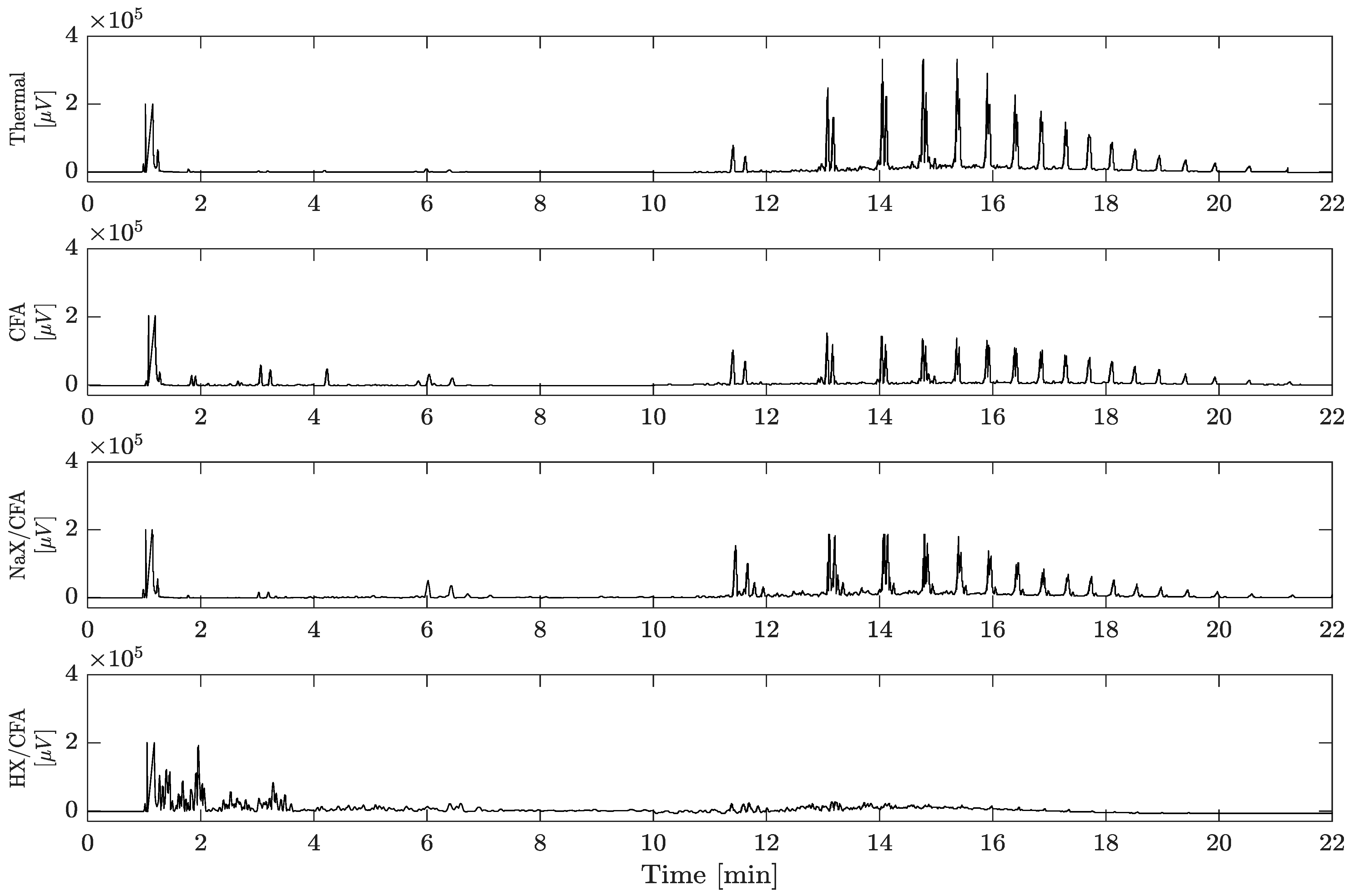
Figure 2 shows a comparison among gas chromatograms of the oils derived from thermal and catalyzed pyrolysis. The first chromatogram, referring to the products of thermal pyrolysis, shows peaks related to aliphatic hydrocarbons with increasing intensity from C6 (barely visible) to C10–C11. Starting from compounds containing 12 carbon atoms, a distinct pattern of peaks having the same number of carbon atoms was detected: the peaks were resolved into triplets of a specific chain length, corresponding to the following classes of hydrocarbons (in eluting order): alkadiene, alkene, and alkane [40], with alkene being predominant. The hydrocarbons in each triplet have one more carbon atom than the molecules in the triplet eluted prior to it. This result is consistent with what was reported previously [40] about the thermal degradation of polyethylene, which is known to occur through a random scission mechanism that causes fragmentation of the original polymer backbone, producing smaller linear chain fragments that may contain any number of carbons [41,42]. These fragments having an unsaturated end and another with a terminal free radical, need to be stabilized via free-radical transfer through either inter- or intramolecular hydrogen chain transfer reactions, which transform the radical fragments into linear chain dienes, alkenes, and alkanes. The second and third gas chromatograms of Figure 2—related to CFA and NaX/CFA pyrolysis, respectively—show no marked qualitative differences from the thermal analysis, but the peaks of the products with lower molecular weight grow in intensity to the detriment of heavier molecules.
Nevertheless, in the presence of HX/CFA the gas chromatogram changes remarkably. In fact, this catalyst shows a marked shape selectivity that produces high concentrations of light hydrocarbons and the complete disappearance of heavier olefins and paraffins.
Furthermore, the chromatogram of HX/CFA shows the production of a wide range of lower molecular weight species that eluted at retention times below 5 min, as well as a wide range of isomers, linear and branched paraffins, olefins, cycled compounds, and aromatics, rather than the corresponding linear hydrocarbons resulting in a highly complex oil mixture. The concentration values of some monoaromatics in the different oils are reported in Table 3, and their low but significant increase during the catalytic pyrolysis over HX/CFA are evident.
This different distribution of products may be reasonably attributed to different degradation mechanisms. Catalytic cracking in the presence of an acid or basic catalyst takes place through an ionic mechanism with cationic and anionic intermediates, respectively. In the base catalyzed degradation mechanism, the reaction starts with abstraction of H+ from the polymer and the metal cations, as Na+ in the NaX/CFA case, stabilize the carbanions. The formation of anionic species from polymer indicates the existence of an electron pair donating sites on the surface of the polymer [43,44]. Differently, acid catalytic cracking proceeds through an ionic path, which involves the formation of carbenium and carbonium ions at the Lewis and Brønsted acid sites of the catalyst, respectively. Besides, both acid sites are external, not limited by steric or diffusional problems; and internal, the latter only being available for the PE straight chains. Even the side-chain methyl groups of PP increases the effective cross-section of the PP molecules compared to the polyethylenic chains, which may prevent their access to the active sites located within the zeolite pores [45,46]. Once the carbocations are formed, different acid-catalyzed reactions may occur over the acid sites—such as isomerization, oligomerization cyclization, aromatization, and hydrogen transfer reactions—which lead to the production of light branched paraffins, olefins, and monoaromatics [46,47]. These reactions may occur randomly in the polymer backbone or preferentially at the end of the chain. The occurrence of one or other possibility depends chiefly on the acid strength and pore structure of the chosen catalyst [48,49].
To better investigate the effect of the different catalysts on the reaction selectivity, Figure 3 shows the percentage distribution in the oils of carbon atoms number of detected compounds for the thermal and catalytic experiments carried out.
As already seen in the related gas chromatograms, for thermal pyrolysis one can notice that the bar chart shapes a single broad peak starting from C9, with a slow decreasing trend ranging from C14 up to C27 that corresponds to a quite regular distribution of carbon numbers. On the other hand, the products obtained during the catalytic processes exhibit narrower distributions, with maximum yield shifting to low molecular weight compounds. In particular, the best performance in terms of product composition for the high selectivity towards light hydrocarbon may be attributed to HX/CFA, with the maximum placed at C7, one of the main components of the gasoline fraction (C6–C9), corresponding to 24.3%. Moreover, the product distribution is narrow since HX/CFA shows a very low selectivity towards organic compounds, where each Ci>15 account for less than 1 wt % of the total amount.
CFA and NaX/CFA have similar selectivity patterns, also showing a better performance than thermal pyrolysis in terms of light hydrocarbons production. In particular, for CFA and NaX/CFA two selectivity maximums are observed for the C8 (15.4% and 13.8%, respectively) and C10 (8.2% and 15.7%, respectively) compounds in the range of gasolines (C6–C9) and heavy naphtha (C10–C13) [50] (p. 63). On the other hand, a wider product distribution is observed with respect to the cracking performed by HX/CFA, showing significant selectivity even for products of the middle distillate region (C14–C22).
The results obtained by the different catalysts can be related to their respective physicochemical properties and in particular to their acidity, in terms of type, strength, and amount of acid sites, as it exerts a strong influence on the catalytic performance, and determines the catalyst activity and selectivity [48]. In particular, the reason for the higher selectivity showed by HX/CFA catalyst toward light hydrocarbons may be related to its stronger acidity with respect to those of NaX/CFA and CFA both in terms of strength and number of active sites. The presence of these sites preferentially favors end-chain cracking reactions of the polymer backbone, originating very light olefins as primary products. These olefins undergo subsequent oligomerization reactions, leading to heavier aliphatic hydrocarbons (C6–C9), a reaction pathway which may explain the maximum found around the C7 fraction in the HX/CFA selectivity pattern. By contrast, the far higher amount of middle distillates (C14−C22) originating from cracking over NaX/CFA and CFA may be related to a random-chain cracking mechanism, which is typical of medium strength acid and base catalysts [46,47,48]. In fact, in the presence of basic catalysts, the reaction starts with abstraction of H+ from the polymer backbone, but further reaction is similar to thermal degradation involving a mechanism consisting of several steps like initiation, hydrogen abstraction, and termination [51,52].
Detailing the distribution of the oil fractions, Figure 3 shows that more than 70% of the oil coming from HX/CFA pyrolysis is constituted by (C6–C9) hydrocarbon range products (representing the gasoline or light naphtha range). This percentage decreases to 28% and 26% for pyrolysis over CFA and NaX/CFA, respectively, while thermal pyrolysis yielded no more than 2% in the same range.
Even for this aspect HX/CFA seems to be the best choice: it increases the percentage of lighter products, and it is able almost completely to get rid of the heavier hydrocarbons. In addition, the oil obtained with HX/CFA contains larger amounts of branched, cyclic, and monoaromatic hydrocarbons (without exceeding the fuels limit of the law [50] (p. 563)), whose presence is positive for the formulation of gasoline (octane number values).
Differently, NaX/CFA can be considered a suitable catalyst for the conversion of polyolefins into heavy naphtha (C10–C13), yielding the maximum value of 44%. For compounds with Ci≥14, namely C14–C22 and C23–C27 (kerosene and gasoil, respectively), NaX/CFA and CFA reached selectivities of 30% and 44%, respectively. Thermal pyrolysis seems to be the best choice for the kerosene fraction (51%), but the very low yield of oil (Table 2) however encourages exploration of other solutions.

2.4. Pyrolysis Gases Characterization

The composition of the gases evolved during the pyrolysis experiments were determined through a GC-TCD and the results are presented in Table 4. According to literature [53], results show that gases from thermal pyrolysis of PE are mainly composed by C1–C3 hydrocarbons, together with some hydrogen and some carbon mono and dioxide, being the latter two originating from the degradation of traces of polyethylene terephthalate and paper in PFR. Other degradation products, namely the C4–C5 isomers, are still present, but not detectable by a GC-TCD.
The most evident effect of using CFA and CFA-derived zeolites for the pyrolysis of PFR is the consistent increase of hydrogen concentration, probably corresponding to their higher char yields (Table 4): a higher production of char where carbon is the main component frees hydrogen from the weaker bonds found in its structure [54].
In any case, the pyrolysis gas mixtures result rich in high calorific organic and inorganic components. Low heating values (LHVs) of the four gaseous mixtures are expressed in MJ·kg−1 and reported in Table 5. The gas originating from NaX/CFA pyrolysis has the highest LHV because the CO2 content is minimum. Once CO2 was removed, for example using NaX/CFA itself as adsorbent material [23], the LHV (second column of Table 5) of all the gaseous mixtures were found considerably increased while the volume to manage decreased with an evident technical and economic advantage.
Beside the opportunity to exploit its potential separating hydrogen and carbon monoxide from the other gases to produce a syngas and recover the organics, whole gas could be used as a fuel, for example to satisfy the pyrolysis energy needs. The combustion energy is obtained by burning the gas originating from pyrolysis of 1 kg of PFR, while the energy needs to pyrolyze 1 kg of PFR with or without a catalyst was calculated from results of DSC measurements (Table 1). It is evident that all the produced gaseous mixtures have more than enough energy to sustain the process and the remaining part (expressed by the net energy) could be used as a versatile energy carrier for other applications. In this case, NaX/CFA shows the best performance because, during the relative pyrolysis, the gas fraction has the highest yield and the most energetic content with a net energy almost twofold higher than that obtained with HX/CFA, despite the higher energy need. Obviously, in an industrial scale plant, pyrolysis gas should be hotter than the reactor where the pyrolysis occurs in order to promote the heat exchange between gas and plastic feed. Hence, the energy really available for the occurrence of a reaction is far less than the potential energy obtainable by the combustion energy calculated from LHV of a gas mixture.

3. Materials and Methods

3.1. Raw Materials

The PFR is the plastic residue of a recycling facility that treats plasmix. PFR is almost entirely constituted by polyolefins (PE film, 92–95 wt % and PP, 3–5 wt %) and it was thermo-chemically characterized in a previous study (Table 6) [28]. Thanks to its product analysis and thermochemical properties, PFR represents a good candidate to run the pyrolysis process [28]. Before loading it into the reactor, PFR was milled to a final particle size <0.5 mm in order to obtain a homogeneous sample, especially when physically mixed with the catalysts.
The raw CFA was the same used by Verrecchia et al. [23] and the production of the CFA-derived zeolite has been carried out following the fusion and hydrothermal method, in particular setting the synthesis parameters to 1.2 NaOH (VWR Chemicals, Leuven, Belgium)/CFA weight ratio, 7 h crystallization time, and 90 °C as the crystallization temperature, according to test run 1, reported in detail in a previous work [23]. The resulting NaX/CFA has a NaX yield of 60 wt %, is characterized by a specific surface area of 498 m2·g−1 and exhibits a CO2 adsorption capacity of 2.18 molCO2·kg−1.
Since in catalytic pyrolysis processes cracking reactions are promoted by acid zeolites [29,55], NaX/CFA has been acidified to HX/CFA zeolite in order to improve its catalytic performance. Acidification was carried out loading NaX/CFA in a round-bottom flask with a 2 M solution of NH4Cl (Clean Consult International, Lodi, Italy) in a 1:4 mass ratio, with the view to exchange Na+ with NH4+ ions. The system was continuously stirred at 100 °C for 3 days under reflux with a water condenser. Each day fresh 2 M solution of NH4Cl was added to the system in the same 1:4 mass ratio. At the end of the third day, NH4X/CFA was recovered by filtering, washed with distilled water and, finally, dried at 100 °C in a stove. Finally, NH4X/CFA was calcined at 400 °C for 4 h under inert atmosphere in order to decompose ammonium ions and produce HX/CFA [56].

3.2. Thermal Analysis

In order to study the effect of the catalysts on the degradation temperature and degradation heat, PFR thermogravimetric analysis (TGA) and differential scanning calorimetry (DSC) were performed simultaneously using a Mettler-Toledo TGA/DSC1 (Columbus, OH, USA). A total mass of 20.0 ± 0.2 mg of a mixture consisting of a 1:1 mass ratio of the sample and the catalyst (CFA, NaX/CFA or HX/CFA) was placed in an alumina crucible, and heated up to 600 °C at a rate of 10 °C·min–1 under 60 mL∙min–1 N2 flow. Preliminary ‘blank experiments’ were performed under the same experimental conditions of the actual experiments using alumina crucibles with 10 mg of the catalyst for catalytic experiments. Each measurement was repeated three times for each sample.

3.3. Pyrolysis Set-Up Description

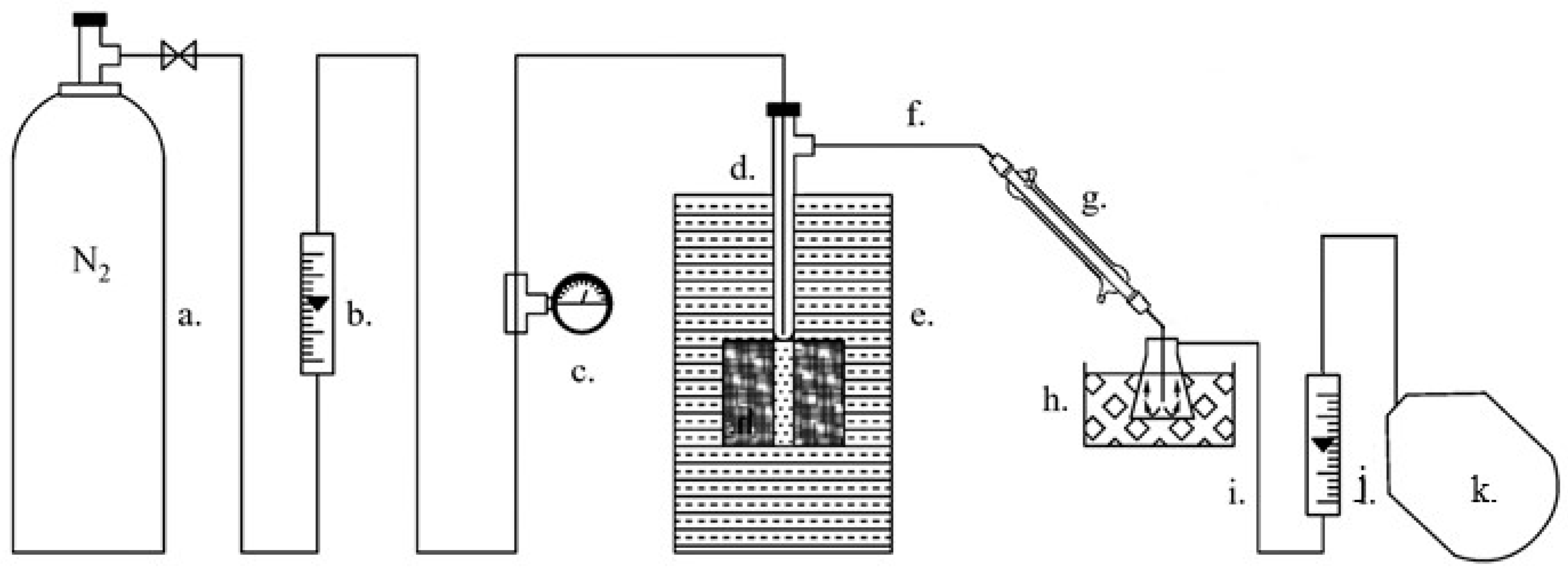
The pyrolysis test was carried out in a hand-made laboratory scale semi-batch reactor at 723 K in accordance with the thermal degradation temperature revealed during a TGA dynamic experiment. The reactor was an updated version of that used by Colantonio et al. [29] (Figure 4). It was a quartz T tube, closed on the bottom side, internal diameter of 18 mm, 240 mm long, heated by an external electric furnace. N2 gas stream was supplied from the top of the reactor in order to make the atmosphere inert and carry the gases and vapors on. The vapors, generated during the pyrolysis, evolved from the reactor by the lateral tube and through the condensation system, made up of a water glass condenser (80 mm in length and 20 mm of external diameter) and a cold trap at 273 K, condensed as a liquid oil and/or a solid wax. Finally, a gas bag was used for the collection of non-condensed gases outgoing from the cold trap.
The solid mixtures of grinded PFR and catalyst powder were prepared through vibration stirring in a glass vial. Approximately 8 g of the mixture PFR/catalyst, 2:1 mass ratio, were placed in the quartz reactor under a flowing N2 gas at ambient temperature. When the furnace reached the desired stable temperature, the reactor loaded with the sample was placed in it, performing in this way an approximately isothermal pyrolysis. The present set-up realizes a liquid-phase configuration because the catalyst gets directly in contact with the melted plastic load [57]. After about 30 min when vapor emissions from the reactor ended, the reaction was considered complete and the experiment was stopped.
After the reactor was cooled to ambient temperature, the char was collected and the mass balance for the product yields could be determined. In particular, the vapor condensed into a liquid in the cold trap and is defined as oil, while the wax solidified and accumulated in the reactor downstream glass tubes and glass condenser at ambient temperature before reaching the cold trap. Oil, wax, and char were directly collected and weighed (the mentioned equipment was also weighed before and after the pyrolysis experiments), while the tar is the viscous, dark brown residue on the quartz reactor walls and its amount were only calculated by the mass difference between the dirty and the clean reactor. In the case of catalytic pyrolysis, the solid fraction consisted of char and catalyst, therefore the char amount was obtained by combustion of the solid fraction and subtracting the mass of the residue catalyst from the initial mass of the collected solid. Finally, the gas yield is calculated as complement to 100 of the sum of the previous yields.

3.4. Pyrolysis Product Characterization

The most valuable products of oil and gas underwent a chemical characterization. In particular, the oil qualitative and quantitative analyses were carried out using two different techniques, respectively: gas chromatography equipped with mass spectrometer (GC-MS), and gas chromatography coupled with a flame ionization detector (GC-FID). In particular, the oils obtained from thermal and catalytic pyrolysis were initially characterized by a Thermo TRACE GC–MS (Waltham, MA, USA) fitted with a DB5-MS capillary column (30 m × 0.25 mm) coated with a 0.25 mm 5% Diphenyl/95% Dimethylpolysiloxane thick film. Helium was used as carrier gas with a constant flow rate of 1.0 mL/min. The temperature of PTV injector was ramped from 40 °C to 250 °C at 14.5 °C∙s−1. The GC oven program keeps the temperature at 40 °C for 2 min, then a ramp at 10 °C∙min−1 up to 80 °C and hold for 1 min, followed by a second ramp at 5 °C∙min−1 up to 320 °C and hold for 5 min. The mass spectrometer electron energy was 70 eV and the ion source and transfer line temperature were 250 °C and 280 °C, respectively. Chromatographic peaks were identified by means of the NIST mass spectral data library and from their retention times using standard compounds, when available.
Subsequent quantitative studies were performed using a Perkin Elmer 8700 (Norwalk, CT, USA) gas chromatograph equipped with a flame ionization detector (FID), with a split/splitless injection port. The capillary column used was an SE-54 (30 m × 0.25 mm × 0.25 μm). Hydrogen was used as a carrier gas. The injector and FID temperatures were both 300 °C. The GC oven was programmed to hold at 45 °C for 10 min, then ramp to 280 °C at 30 °C∙min−1, and held for a further 5 min. The oil samples, spiked with internal standard, were injected after dilution in pentane at 1%.
Pyrolysis permanent gases and light hydrocarbons, collected inside the gas bag (CO2, CO, H2, N2, O2, CH4, C2H6, C2H4, C2H2, C3H8, C3H6), were analyzed using a Thermo Scientific TRACE Ultra GC (Waltham, MA, USA), coupled with a thermal conductivity detector (TCD). The column used was a CARBOXEN 1010 PLOT packed with silica and being helium the carrier gas. The GC oven temperature was kept at 40 °C for 7.5 min, programmed to reach 200 °C at a rate of 50 °C∙min−1, and held for a further 10 min, followed by a second ramp up to 280 °C at 50 °C∙min−1, and held at this temperature for 5 min. The concentrations of these gaseous components are reported in a N 2 -free basis, since N 2 was the carrier gas in the pyrolysis experiment. Finally, LHV of the gases was theoretically calculated according to their composition and to the LHV of the individual components reported in [58].

4. Conclusions

In this work, CFA and CFA-derived zeolites have been successfully tested as catalysts for the conversion of a packaging plastic waste (a polyolefin mixture residual from a recycling plant) to valuable hydrocarbon products. CFA was used as it is while CFA-derived zeolites were synthetized from CFA through fusion with NaOH followed by hydrothermal method, NaX/CFA, and further acidification in the case of HX/CFA.
PFR proved to be an excellent feed for pyrolysis conversion to fuel because of the scarce content of heteroatoms and foreign materials and in view of the fact that the resulting oil is mainly composed by aliphatic hydrocarbons. Unfortunately, during thermal pyrolysis oil is only a small fraction, while the main products are wax and tar.
All the three used catalysts exhibited a good cracking effect, but the best results were obtained by HX/CFA, which has shown performance similar, even if weaker, to a commercial zeolite such as HUSY zeolite. As a matter of fact, HX/CFA has reduced the endothermic energy requested by pyrolysis and it has improved the gas yield, the oil yield, as well as the product selectivity towards the gasoline range to the detriment of heavier fractions. NaX/CFA, instead, has favored the formation of heavy naphtha, but the most interesting result regards the quantity and quality of the gas produced. Furthermore, CFA has totally inhibited wax formation and favored the C6–C9 and C10–C13 fractions in the oil, but to a lesser extent if compared to the derived zeolites. Since CFA has a null cost and no pre-treatment has been requested to be used as a catalyst (except calcination if the amount of unburned carbon is consistent), its use mixed with PFR could be evaluated, also in large amount, pelletized and loaded in a continuous pyrolysis reactor.
Nevertheless, the final choice upon the best catalyst depends on many factors—i.e., the desired products, a cost–benefit analysis, the reactor configuration, and the plastic load. Regarding the last issue, it will be interesting to evaluate the performance of these low-cost catalysts on different plastic materials, such as styrene-based or condensation polymers.
As far as the outlook for future trends is concerned, the use of waste material for production of catalysts could represent a further improvement for pyrolysis sustainability and circularity.

Author Contributions

Conceptualization, R.T. and S.V.C.; Methodology, R.T., S.V.C., and D.D.A.; Investigation, P.N., D.D.A., and M.C.; Resources, R.T. and V.P; Writing—original draft preparation, M.C., L.M., D.D.A., and R.T.; Writing—review and editing, R.T., S.V.C., and M.C.; Visualization, M.C. and L.M.; Supervision, R.T., S.V.C., and V.P. All authors have read and agreed to the published version of the manuscript.

Funding

This research received no external funding.

Conflicts of Interest

The authors declare no conflict of interest.

References

  1. Packaging Waste Statistics—Eurostat. Available online: https://ec.europa.eu/eurostat/statistics-explained/index.php/Packaging_waste_statistics (accessed on 22 July 2020).
  2. PCEP—A key platform to drive polyolefins circularity. 2018. Available online: https://pcep.eu/our-commitments (accessed on 22 July 2020).
  3. Plastics Europe. Plastics—The Facts 2019: An Analysis of European Latest Plastics Production, Demand and Waste Data; Plastics Europe: Wemmel, Belgium, 2019. [Google Scholar]
  4. Directive 2018/852/EU of the European Parliament and of the Council of 30 May 2018 Amending Directive 94/62/EC on Packaging and Packaging Waste; EU: Strasbourg, France, 2018.
  5. Directive 2004/12/EC of the European Parliament and of the Council Amending Directive 94/62/EC on Packaging and Packaging Waste; EU: Strasbourg, France, 2014.
  6. PlasticsEurope. The Circular Economy for Plastics—A European Overview; PlasticsEurope: Brussels; Belgium, 2019. [Google Scholar]
  7. Fondazione per lo sviluppo sostenibile. 2019 Italia del Riciclo; Fondazione per lo sviluppo sostenibile: Rome, Italy, 2019. (In Italian) [Google Scholar]
  8. Ragaert, K.; Delva, L.; Van Geem, K. Mechanical and chemical recycling of solid plastic waste. Waste Manag. 2017, 69, 24–58. [Google Scholar] [CrossRef] [PubMed]
  9. Kaminsky, W. Chemical recycling of mixed plastics of pyrolysis. Adv. Polym. Technol. 1995, 14, 337–344. [Google Scholar] [CrossRef]
  10. Miandad, R.; Rehan, M.; Nizami, A.S.; Barakat, M.A.E.F.; Ismail, I.M. The Energy and Value-Added Products from Pyrolysis of Waste Plastics. In Recycling of Solid Waste for Biofuels and Bio-Chemicals; Springer: Singapore, 2016. [Google Scholar]
  11. Miandad, R.; Barakat, M.A.; Aburiazaiza, A.S.; Rehan, M.; Ismail, I.M.I.; Nizami, A.S. Effect of plastic waste types on pyrolysis liquid oil. Int. Biodeterior. Biodegrad. 2017, 119, 239–252. [Google Scholar] [CrossRef]
  12. Miandad, R.; Barakat, M.A.; Aburiazaiza, A.S.; Rehan, M.; Nizami, A.S. Catalytic pyrolysis of plastic waste: A review. Process Saf. Environ. Prot. 2016, 102, 822–838. [Google Scholar] [CrossRef]
  13. Aguado, J.; Serrano, D.P.; San Miguel, G.; Castro, M.C.; Madrid, S. Feedstock recycling of polyethylene in a two-step thermo-catalytic reaction system. J. Anal. Appl. Pyrolysis 2007, 79, 415–423. [Google Scholar] [CrossRef]
  14. Butler, E.; Devlin, G.; McDonnell, K. Waste polyolefins to liquid fuels via pyrolysis: Review of commercial state-of-the-art and recent laboratory research. Waste Biomass Valoriz. 2011, 2, 227–255. [Google Scholar] [CrossRef] [Green Version]
  15. Coelho, A.; Costa, L.; Marques, M.M.; Fonseca, I.M.; Lemos, M.A.N.D.A.; Lemos, F. The effect of ZSM-5 zeolite acidity on the catalytic degradation of high-density polyethylene using simultaneous DSC/TG analysis. Appl. Catal. A Gen. 2012, 413–414, 183–191. [Google Scholar] [CrossRef]
  16. Hakeem, I.G.; Aberuagba, F.; Musa, U. Catalytic pyrolysis of waste polypropylene using Ahoko kaolin from Nigeria. Appl. Petrochem. Res. 2018, 8, 203–210. [Google Scholar] [CrossRef] [Green Version]
  17. Na, J.-G.; Jeong, B.-H.; Chung, S.H.; Kim, S.-S. Pyrolysis of low-density polyethylene using synthetic catalysts produced from fly ash. J. Mater. Cycles Waste Manag. 2006, 8, 126–132. [Google Scholar] [CrossRef]
  18. González, A.; Navia, R.; Moreno, N. Fly ashes from coal and petroleum coke combustion: Current and innovative potential applications. Waste Manag. Res. 2009, 27, 976–987. [Google Scholar] [CrossRef]
  19. Zhuang, X.Y.; Chen, L.; Komarneni, S.; Zhou, C.H.; Tong, D.S.; Yang, H.M.; Yu, W.H.; Wang, H. Fly ash-based geopolymer: Clean production, properties and applications. J. Clean. Prod. 2016, 125, 253–267. [Google Scholar] [CrossRef]
  20. Bhatt, A.; Priyadarshini, S.; Acharath, A.; Abri, A.; Sattler, M.; Techapaphawit, S. Case Studies in Construction Materials Physical, chemical, and geotechnical properties of coal fl y ash: A global review. Case Stud. Constr. Mater. 2019, 11, e00263. [Google Scholar] [CrossRef]
  21. Gaurh, P.; Pramanik, H. Production of benzene/toluene/ethyl benzene/xylene (BTEX) via multiphase catalytic pyrolysis of hazardous waste polyethylene using low cost fly ash synthesized natural catalyst. Waste Manag. 2018, 77, 114–130. [Google Scholar] [CrossRef] [PubMed]
  22. Mehra, A.; Farago, M.E.; Banerjee, D.K. Impact of fly ash from coal-fired power stations in Delhi, with particular reference to metal contamination. Environ. Monit. Assess. 1998, 50, 15–35. [Google Scholar] [CrossRef]
  23. Verrecchia, G.; Cafiero, L.; de Caprariis, B.; Dell’Era, A.; Pettiti, I.; Tuffi, R.; Scarsella, M. Study of the parameters of zeolites synthesis from coal fly ash in order to optimize their CO2 adsorption. Fuel 2020, 276, 118041. [Google Scholar] [CrossRef]
  24. Tauanov, Z.; Shah, D.; Itskos, G.; Inglezakis, V. Optimized Production of Coal Fly Ash Derived Synthetic Zeolites for Mercury Removal from Wastewater. IOP Conf. Ser. Mater. Sci. Eng. 2017, 230, 012044. [Google Scholar] [CrossRef] [Green Version]
  25. Zhang, S.; Tang, W.; Li, L.; Li, H.; Sun, J.; Gu, X.; Chen, S.; Peng, X.; Bourbigot, S. Fabrication of Fly Ash-Based Mesoporous Aluminosilicate Oxides Loaded with Zinc and its Synergistic Fire Resistancy in Polypropylene. J. Vinyl Addit. Technol. 2019, 26, 135–143. [Google Scholar] [CrossRef]
  26. Kim, S.S.; Kim, J.H.; Chung, S.H. A study on the application of fly ash-derived zeolite materials for pyrolysis of polypropylene. J. Ind. Eng. Chem. 2003, 9, 287–293. [Google Scholar]
  27. Singh, S.T.; Kant, K.; Singh, K.; Singh, S.P. Low Cost Catalyst Synthesized from Coal Fly-Ash for regaining Liquid Fuel from HDPE and its Kinetic Analysis. J. Chem. Petrochem. Technol. 2013, 3, 31–40. [Google Scholar]
  28. Ippolito, N.M.; Cafiero, L.; Tuffi, R.; Vecchio Ciprioti, S. Characterization of the residue of a commingled post-consumer plastic waste treatment plant: A thermal, spectroscopic and pyrolysis kinetic study. J. Therm. Anal. Calorim. 2019, 138, 3323–3333. [Google Scholar] [CrossRef]
  29. Colantonio, S.; Cafiero, L.; De Angelis, D.; Ippolito, N.M.; Tuffi, R.; Ciprioti, S.V. Thermal and catalytic pyrolysis of a synthetic mixture representative of packaging plastics residue. Front. Chem. Sci. Eng. 2020, 14, 288–303. [Google Scholar] [CrossRef]
  30. Marcilla, A.; García-Quesada, J.C.; Sánchez, S.; Ruiz, R. Study of the catalytic pyrolysis behaviour of polyethylene-polypropylene mixtures. J. Anal. Appl. Pyrolysis 2005, 74, 387–392. [Google Scholar] [CrossRef]
  31. Marcilla, A.; Gómez-Siurana, A.; Berenguer, D. Study of the influence of the characteristics of different acid solids in the catalytic pyrolysis of different polymers. Appl. Catal. A Gen. 2006, 301, 222–231. [Google Scholar] [CrossRef]
  32. Lopez, G.; Artetxe, M.; Amutio, M.; Bilbao, J.; Olazar, M. Thermochemical routes for the valorization of waste polyolefinic plastics to produce fuels and chemicals. A review. Renew. Sustain. Energy Rev. 2017, 73, 346–368. [Google Scholar] [CrossRef]
  33. Chen, Z.; Liu, Z.; Liu, Q.; Shi, L.; Xu, T. Pyrolysis Tar Conversion. U.S. Patent 10072218-B2, 11 September 2018. [Google Scholar]
  34. Arabiourrutia, M.; Elordi, G.; Lopez, G.; Borsella, E.; Bilbao, J.; Olazar, M. Characterization of the waxes obtained by the pyrolysis of polyolefin plastics in a conical spouted bed reactor. J. Anal. Appl. Pyrolysis 2012, 94, 230–237. [Google Scholar] [CrossRef]
  35. Onwudili, J.A.; Insura, N.; Williams, P.T. Composition of products from the pyrolysis of polyethylene and polystyrene in a closed batch reactor: Effects of temperature and residence time. J. Anal. Appl. Pyrolysis 2009, 86, 293–303. [Google Scholar] [CrossRef]
  36. De Marco, I.; Caballero, B.M.; López, A.; Laresgoiti, M.F.; Torres, A.; Chomón, M.J. Pyrolysis of the rejects of a waste packaging separation and classification plant. J. Anal. Appl. Pyrolysis 2009, 85, 384–391. [Google Scholar] [CrossRef]
  37. Esposito, L.; Cafiero, L.; De Angelis, D.; Tuffi, R.; Vecchio Ciprioti, S. Valorization of the plastic residue from a WEEE treatment plant by pyrolysis. Waste Manag. 2020, 112, 1–10. [Google Scholar] [CrossRef]
  38. Santella, C.; Cafiero, L.; De Angelis, D.; La Marca, F.; Tuffi, R.; Vecchio Ciprioti, S. Thermal and catalytic pyrolysis of a mixture of plastics from small waste electrical and electronic equipment (WEEE). Waste Manag. 2016, 54, 143–152. [Google Scholar] [CrossRef]
  39. Benedetti, M.; Cafiero, L.; De Angelis, D.; Dell’Era, A.; Pasquali, M.; Stendardo, S.; Tuffi, R.; Ciprioti, S.V. Pyrolysis of WEEE plastics using catalysts produced from fly ash of coal gasification. Front. Environ. Sci. Eng. 2017, 11, 11. [Google Scholar] [CrossRef]
  40. Wampler, T.P. Thermometric behavior of polyolefins. J. Anal. Appl. Pyrolysis 1989, 15, 187–195. [Google Scholar] [CrossRef]
  41. Serrano, D.P.; Aguado, J.; Escola, J.M.; Rodríguez, J.M.; San Miguel, G. An investigation into the catalytic cracking of LDPE using Py–GC/MS. J. Anal. Appl. Pyrolysis 2005, 74, 370–378. [Google Scholar] [CrossRef]
  42. Williams, P.T.; Williams, E.A. Fluidised bed pyrolysis of low density polyethylene to produce petrochemical feedstock. J. Anal. Appl. Pyrolysis 1999, 51, 107–126. [Google Scholar] [CrossRef]
  43. Rasul Jan, M.; Shah, J.; Gulab, H. Degradation of waste High-density polyethylene into fuel oil using basic catalyst. Fuel 2010, 89, 474–480. [Google Scholar] [CrossRef]
  44. Rasul Jan, M.; Shah, J.; Gulab, H. Catalytic conversion of waste high-density polyethylene into useful hydrocarbons. Fuel 2013, 105, 595–602. [Google Scholar] [CrossRef]
  45. Zhao, W.; Hasegawa, S.; Fujita, J.; Fumio, Y.; Sasaki, T. Effects of zeolites on the pyrolysis of polypropylene. Polym. Degrad. Stab. 1996, 53, 129–135. [Google Scholar] [CrossRef]
  46. Aguado, J.; Serrano, D.P.; Sotelo, J.L.; Van Grieken, R.; Escola, J.M. Influence of the Operating Variables on the Catalytic Conversion of a Polyolefin Mixture over HMCM-41 and Nanosized HZSM-5. Ind. Eng. Chem. Res. 2001, 40, 5696–5704. [Google Scholar] [CrossRef]
  47. Serrano, D.P.; Aguado, J.; Escola, J.M. Catalytic Cracking of a Polyolefin Mixture over Different Acid Solid Catalysts. Ind. Eng. Chem. Res. 2000, 39, 1177–1184. [Google Scholar] [CrossRef]
  48. Serrano, D.P.; Aguado, J.; Escola, J.M. Developing Advanced Catalysts for the Conversion of Polyolefinic Waste Plastics into Fuels and Chemicals. ACS Catal. 2012, 2, 1924–1941. [Google Scholar] [CrossRef]
  49. Marcilla, A.; Beltrán, M.I.; Navarro, R. Thermal and catalytic pyrolysis of polyethylene over HZSM5 and HUSY zeolites in a batch reactor under dynamic conditions. Appl. Catal. B Environ. 2009, 86, 78–86. [Google Scholar] [CrossRef]
  50. Hsu, C.S.; Robinson, P.R. Handbook Petroleum Technology; Springer: Cham, Switzerland, 2017; ISBN 9783319493459. [Google Scholar]
  51. Tanabe, K.; Misono, M.; Ono, Y.; Hattori, H. New Solid Acids and Bases Their Catalytic Properties; Elsevier: Amsterdam, The Netherlands, 1989; Volume 51, ISBN 9780444988003. [Google Scholar]
  52. Jan, M.R.; Shah, J.; Gulab, H. Catalytic degradation of waste high-density polyethylene into fuel products using BaCO3 as a catalyst. Fuel Process. Technol. 2010, 91, 1428–1437. [Google Scholar] [CrossRef]
  53. Bagri, R.; Williams, P.T. Catalytic pyrolysis of polyethylene. J. Anal. Appl. Pyrolysis 2002, 63, 29–41. [Google Scholar] [CrossRef]
  54. Imam, T.; Capareda, S. Characterization of bio-oil, syn-gas and bio-char from switchgrass pyrolysis at various temperatures. J. Anal. Appl. Pyrolysis 2012, 93, 170–177. [Google Scholar] [CrossRef]
  55. Al-Salem, S.M.; Antelava, A.; Constantinou, A.; Manos, G.; Dutta, A. A review on thermal and catalytic pyrolysis of plastic solid waste (PSW). J. Environ. Manag. 2017, 197, 177–198. [Google Scholar] [CrossRef] [PubMed]
  56. Warner, T.E.; Galsgaard Klokker, M.; Nielsen, U.G. Synthesis and Characterization of Zeolite Na–Y and Its Conversion to the Solid Acid Zeolite H–Y. J. Chem. Educ. 2017, 94, 781–785. [Google Scholar] [CrossRef]
  57. Sakata, Y.; Uddin, M.A.; Koizumi, K.; Murata, K. Catalytic degradation of polypropylene into liquid hydrocarbons using silica-alumina catalyst. Chem. Lett. 1996, 25, 245–246. [Google Scholar] [CrossRef]
  58. He, M.; Xiao, B.; Hu, Z.; Liu, S.; Guo, X.; Luo, S. Syngas production from catalytic gasification of waste polyethylene: Influence of temperature on gas yield and composition. Int. J. Hydrogen Energy 2009, 34, 1342–1348. [Google Scholar] [CrossRef]
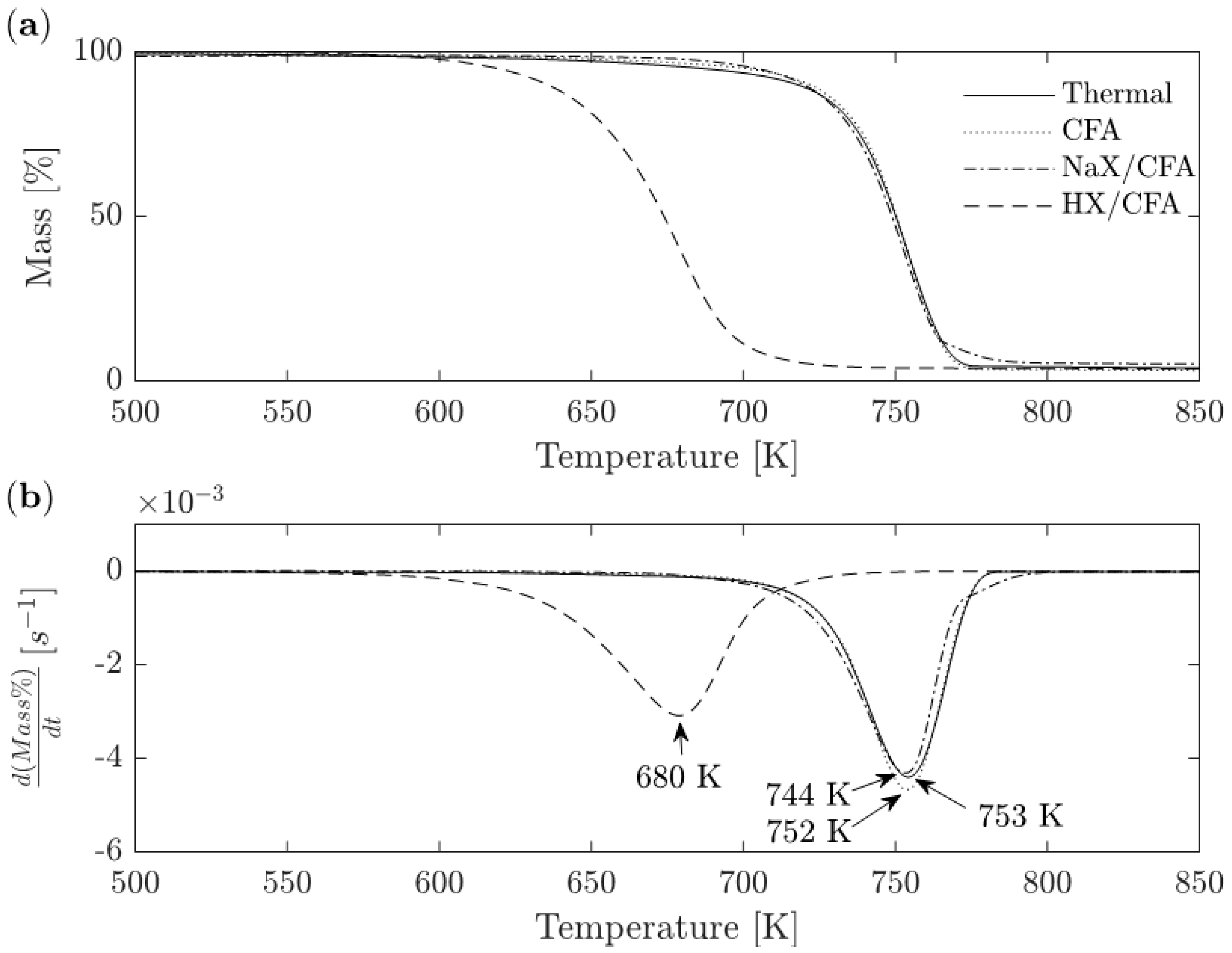
Figure 1. (a) TG and (b) DTG curves describing thermal and catalytic (CFA, NaX/CFA, HX/CFA) degradation of PFR (thermal experiment comes from Ippolito et al. [28]).
Catalysts 10 01113 g001
Figure 2. Gas chromatogram of oils produced from thermal and catalyzed pyrolysis (CFA, NaX/CFA, and HX/CFA).
Catalysts 10 01113 g002
Figure 3. Selectivity by carbon atom number of compounds generated from thermal and catalytic pyrolysis.
Catalysts 10 01113 g003
Figure 4. Pyrolysis experimental set-up: (a) N2 cylinder, (b) upstream flowmeter, (c) manometer, (d) quartz tube reactor, (e) electric furnace, (f) glass tube connector, (g) glass water condenser, (h) ice-bath cooled conical flask, (i) connection tygon tube, (j) downstream flowmeter, (k) gas sample bag.
Catalysts 10 01113 g004
Table 1. Liquid sensible, decomposition, and total degradation heats of PFR during thermal and catalytic degradation (CFA, NaX/CFA, HX/CFA). Solid sensible and fusion heats remain unchanged during catalytic degradation.
Sensible Heat Formulas
Solid sensible heat * Q S = C p S P E   ( 389   K 298   K )
Liquid sensible heat Q L = C p L P E   ( T d e g 389   K )
Total degradation heat Q T = Q s + Q m e l t i n g P E + Q m e l t i n g P P + Q L + Q d
SampleLiquid Sensible Heat (J/g)Decomposition Heat (J/g)Total Degradation Heat (J/g)
PFR *9711075 ± 1472266
PFR + CFA9711044 ± 282234
PFR + NaX/CFA944903 ± 1442069
PFR + HX/CFA774469 ± 251465
* Ippolito et al. [28]: Qs = 140 J/g; Q m e l t i n g P E = 78 J/g; Q m e l t i n g P P = 1.8 J/g. In sensible heat equations PFR was considered only made of PE that accounts for almost the 95 wt %.
Table 2. Comparison of products yields by thermal and catalytic pyrolysis of PFR at 723 K.
PFR (wt %)CFA (wt %)NaX/CFA (wt %)HX/CFA (wt %)
Oil5 ± 136.2 ± 0.718 ± 144 ± 1
Tar39 ± 19.1 ± 0.121 ± 17.2 ± 0.2
Wax26 ± 2n.d.n.d.n.d.
Gas25 ± 133.9 ± 0.442 ± 131 ± 2
Char 5.4 ± 0.120.7 ± 0.219.8 ± 0.117.3 ± 0.5
n.d.: not detected.
Table 3. Content of benzene, toluene, ethylbenzene, and xylenes, expressed as mg of hydrocarbon/L of oil, in the different pyrolysis tests
Benzene (mg/L)Toluene (mg/L)Ethyl-Benzene (mg/L)m + p-Xylene (mg/L)o-Xylene (mg/L)
Thermal<0.1<0.1<0.1<0.1<0.1
CFA0.4 ± 0.12.2 ± 0.91.0 ± 0.10.3 ± 0.1<0.1
NaX/CFA<0.10.2 ± 0.10.85 ± 0.10.2 ± 0.1<0.1
HX/CFA2.4 ± 0.11.3 ± 0.11.36 ± 0.20.46 ± 0.3<0.1
Table 4. Chemical composition of pyrolysis gases.
Inorganics (v%)Organics (v%)
H2COCO2CH4C2H4C2H6C3H6C3H8
Thermal6 ± 25 ± 212 ± 213 ± 516 ± 120 ± 118 ± 110 ± 1
CFA13 ± 84 ± 115 ± 213 ± 212 ± 116 ± 2 17 ± 210 ± 2
NaX/CFA24 ± 32.4 ± 0.17.8 ± 0.315 ± 116 ± 218.2 ± 0.410.5 ± 0.38 ± 1
HX/CFA30 ± 85 ± 117 ± 68 ± 36 ± 18 ± 122 ± 34.2 ± 0.5
Table 5. LHV, LHV on CO2-free basis, and energy of combustion of the gaseous mixture produced during thermal and catalytic pyrolysis
LHV
(MJ kg−1)
LHVCO2-free (MJ kg−1)Combustion Energy (MJ kg−1)Pyrolysis Energy Needs (MJ kg−1)Net Energy (MJ kg−1)
Thermal37.645.39.42.37.1
CFA35.545.512.02.29.8
NaX/CFA41.047.617.22.115.1
HX/CFA32.946.210.21.58.7
Table 6. PFR proximate and ultimate analyses [28].
PFR Proximate AnalysisHumidityAshesVolatile MatterFixed Carbon
wt %0.27 ± 0.040.9 ± 0.298.6 ± 0.20.21 ± 0.01
PFR Ultimate AnalysisCHNOCl
wt %84 ± 113.8 ± 0.11.8 ± 0.10.85 ± 0.020.10 ± 0.05