Contact Glow Discharge Electrolysis: Effect of Electrolyte Conductivity on Discharge Voltage


1
Department of Chemistry, University of Rome “La Sapienza”, 00185 Piazzale Aldo Moro 5, 00178 Rome, Italy
2
Department of Chemistry, University of Turin, Via Pietro Giuria 7, 10125 Turin, Italy
*
Authors to whom correspondence should be addressed.
Catalysts 2020, 10(10), 1104; https://doi.org/10.3390/catal10101104
Submission received: 29 August 2020
/
Revised: 18 September 2020
/
Accepted: 21 September 2020
/
Published: 24 September 2020
(This article belongs to the Special Issue Advanced Strategies for Catalyst Design)
Abstract
:Contact glow discharge electrolysis (CGDE) can be exploited in environmental chemistry for the degradation of pollutants in wastewater. This study focuses on the employment of cheap materials (e.g., steel and tungsten) as electrodes for experiments of CGDE conducted in electrochemical cells with variable electrolytic composition. A clear correlation between breakdown voltage (VB)/discharge (or midpoint) voltage (VD) and the conductivity of the electrolyte is shown. Regardless of the chemical nature of the ionogenic species (acid, base or salt), the higher the conductivity of the solution, the lower the applied potential required for the onset of the glow discharge. Concerning practical application, these salts could be added to poorly conductive wastewaters to increase their conductivity and thus reduce the ignition potential necessary for the development of the CGDE. Such an effect could render the process of chemical waste disposal from wastewaters more economical. Moreover, it is evidenced that both VB and VD are practically independent on the ratio anode area to cathode area if highly conductive solutions are employed.
1. Introduction
Plasma generated through a process of CGDE constitutes an unconventional product of electrolysis. Starting from the electrolysis in a water solution under DC conditions, it makes the development of a luminescent plasma layer at the electrode/electrolyte interface feasible [1]. Plasma can be formed either at the cathode or at the anode, depending on the operative conditions [2,3,4]. The glow discharge follows water electrolysis (with production of H2 and O2 at the cathode and the anode, respectively) and is further promoted by the formation of radical species (and their derivatives) at the interface between the plasma and the solution [5]. To date, CGDE has been proved to be a valid and cost-effective metal surface treatment technique: the method significantly and effectively increase hardness and corrosion resistance of the metal [4,6].
The CGDE phenomenon occurs for the application of a high voltage (in the order of several hundred of volts) and is characterized by a critical value of onset for the formation of the plasma [3]. Such a voltage onset mainly depends on the physical properties of the electrolyte. Once reached, a gaseous layer surrounding the electrode is formed. The gas of the layer is partly formed by water steam, due to the heating of the solution in proximity of the electrode (Joule effect) and by the products of water electrolysis [4,5]). The profile of the current intensity is characterized by the reaching of a maximum that is followed by decrease. Such a current decrease sets the end the ordinary electrolysis. The critical ignition voltage is called breakdown voltage (VB). A further increase in the voltage leads to the stabilization of the gaseous layer around the electrode in concomitance with the continuous and slow decrease of current. The simplified mathematical model reported in ref. [1] describes the time evolution of the current in CGDE conditions through the equation:
being Rk the total electrical resistance (mainly constituted by the ohmic drop in the interelectrode space), Ud the water decomposition potential and a time constant depending on the system. It is also possible to calculate the time required for the formation of the gas film around one of the two electrodes, using the following expression:
where b is the radius of the cylindrical electrode, h the depth of the cylinder–electrode immersed in the electrolyte, I the current intensity, Tc the boiling temperature of the solvent (reached at the electrode surface) and To is the bulk temperature of the electrolyte having electrical conductivity k, density ρ and specific heat capacity c. This vapor film successively undergoes a transformation into a brilliant, continuous plasma which represents the peculiarity of CGDE. As previously outlined, this phenomenon occurs once the voltage is high enough to trigger the development of plasma. Plasma triggering is characterized by small and quick intermittent glow discharges that are located on the electrode surface with a spotty appearance. The electrode on which plasma is generated is indicated as active electrode [1]. The voltage required for the generation of luminescence is called midpoint voltage or discharge voltage (VD), and the potential region between VB and VD is called partial CGDE. When VD is exceeded, the current intensity starts to rise again, but with a significantly lower slope than the increase observed at voltages lower than VB. Such a regime is called ohmic region. Complete CGDE can be formed at any valued of voltage comprised in the range delimitated by the breakdown and the midpoint voltage. The occurrence of the formation of the latter event depends on the operating conditions of the cell and the polarity of the electrode. The CGDE phenomenon can occur during the electrolysis of aqueous solutions with high conductivity, non-aqueous electrolytes or melts [4,7]. In the present work, we considered prevalently aqueous electrolytes.
Recently, several studies reported on the potential application of CGDE in other sectors, such as the synthesis of tailored nanoparticles [8,9,10], organic compounds [11], steam generation [12], polymers [13,14] and super-adsorbent compounds [15], mineralization of water [16,17,18,19,20,21,22,23,24,25,26,27,28,29,30,31,32] and hydrogen production [33]. Another interesting application consists in the employment of CGDE in the synthesis of amino acids [34]. The versatility of CGDE in the fields of environmental chemistry, electrochemistry, plasma chemistry, organic and inorganic chemistry, coupled with its modest cost compared to other plasma method, fully justifies its in-depth study. Furthermore, a relatively simple experimental apparatus is required. The current–voltage characteristic curves of CGDE have a general typical shape, regardless of the electrode material or the electrolyte used [25,29,35,36,37,38,39].
Again, all curves have two values of fundamental practical interest: the ignition voltage, called breakdown voltage (VB)—at which the collapse of the normal electrolysis occurs—and the midpoint voltage or discharge voltage (VD), i.e., the voltage required for the formation of the actual luminescence, (Figure 1). Since the achievement of the VB is always followed by a rapid decrease of the current, it is easy to identify this value as the maximum in the I–V curves of the CGDE. On the other hand, VD is always followed by a sudden increase of the current (and it is associated with a relative minimum of current in the characteristic curve). Therefore, it is relatively handy to identify the two voltage parameters that determine the development of CGDE. In the present work, these parametric values were systematically analyzed as a function of the variables involved in each type of experiment (conductivity and concentration of the electrolyte, electrode active area, chemical nature of the electrode material, electrolyte solvent).
Due to the complexity of CGDE phenomenon, further studies are still required to understand the mechanisms of electrolyte plasma formation. In this context, the present work focuses on the analysis of the operative conditions for the realization of CGDE. The work deals with the dependence of discharge voltage and the breakdown voltage on electrolyte conductivity and the influence that the difference of the immersed areas of anode and cathode exerts on the two characteristic voltages. As far as we are aware, there is not any study investigating both a so large range of conductivity (up to 600 mS m−1) and a plethora of different electrolytic solutions, also considering a hybrid organic–aqueous environment.
2. Results and Discussion
The present study aims to define the optimal experimental conditions for the development of CGDE in both aqueous and aqueous/organic mixed solvents (namely water and glycerol mixture). Various solutes, at different concentration, were employed in order to evidence any eventual common trend of the voltage parameters with electrolyte conductivity and the area of the active electrode.
An interesting—and almost unique—feature of the CGDE is the tendency to produce molecules (originating from the plasma electrolysis), the faradaic yields of which deviate in excess from theoretical values [4,5,13,40,41,42]. Indeed, more than 80% of the electrolyzed molecules originate in the liquid phase at the interface close to the plasma (i.e., at the electrode surface) where H2O+gas reacts with water molecules leading to the formation of both hydroxyl and proton radicals (H● e OH●). The latter are responsible for a higher gas evolution than expected [41]. Common reactions are briefly recalled hereafter:
H2O+gas + nH2O → (n + 1) H● + (n + 1) OH●
OH● + OH● → ½ O2 + H2O
H● + H● → H2
OH● + OH● → H2O2
OH● + H2O2 → HOO● + H2O
HOO● + OH● → O2 + H2O
The presence of a radical scavenger—such as an aliphatic alcohol—will further promote these reaction (vide infra).
2.1. CGDE in Aqueous Environment: Dependence on Solution Conductivity
In this section, the breakdown and the discharge voltage are analyzed as a function of electrolyte conductivity. Although KCl is a very well-known standard electrolyte in electrochemistry due to its large availability, low cost, negligible toxicity and high solubility in water, it presents the disadvantage of being electroactive with the anodic evolution of Cl2 under the harsh conditions of CGDE. In fact, Cl2 can react spontaneously with steel-based electrodes leading to the formation of iron chloride with the consequent deactivation of the electrode. For this simple reason, in the series of experiments we conducted, tungsten (W) electrodes were employed. The choice of W as electrode material was motivated by its high corrosion resistivity, the high conductivity and availability.
It has been recognized that the conductivity of the solution plays a decisive role in the determination of the value of the potential necessary for the transition from normal electrolysis to CGDE [39,43]. Lower specific conductivities of the electrolyte are associated with higher triggering voltages, while extremely high conductivities lead to a flattening of the VD-k curve. This is observed for both VB and VD. Straightforwardly, we analyze VB and VD values obtained from different experiments using different solutions and different electrodes, as a function of the specific conductivities (mS cm−1) of the fresh solutions. This approach allows to evidence any possible common trend in different starting conditions (i.e., different solutes and concentrations). In Figure 2 we reported the trend of the breakdown voltage with respect to the conductivity of the solution for cathode/anode immersed area ratio ranging from 0.05 to 0.9. In doing so we investigate the electrolytic plasma developed at the cathode surface. Under the adopted conditions, the formation of plasma was always observed at the cathode (Video S1—see Supplementary Materials).
From Figure 2 (top), one notices a rapid increase of VB upon the decrease of k, and when electrolyte conductivity approaches the zero value there is a corresponding exponential augmentation of VB. Highly conductive solutions, namely in the range 80–600 mS cm−1, lead to a quasi-constant value of VB with the latter showing an asymptotic behavior towards a minimum of 30 V. The latter could be set as a threshold value for the occurrence of CGDE phenomenon. This behavior is poorly dependent on the nature of the employed electrolyte, i.e., if this is acid, basic or a salt. Such a behavior could be profitably used for the optimization of the conditions under which CDGE breakdown is conducted for practical applications, e.g., wastewater purification.
The trend of VD vs k shows a larger dispersion of the midpoint voltage with respect to the averaged profile (Figure 2, bottom). The solutions with similar conductivity display comparable VD values. Similar to VB (Figure 2, bottom), also VD tends asymptotically to a minimum upon increase of the conductivity. The asymptotic value of VD is 90 V when conductivity surpasses 80 mS cm−1.
As one can see from Figure 3 and Figure S1 (see supporting information), when the analysis is focused on the experiments of cathodic plasma formation (this is achieved when the ratio of the cathode area/anode area is lower than one, the value of VB is dependent on the conductivity of the solution regardless the nature of the supporting electrolyte. The observed trend recalls what was previously found when only one type of electrolyte is used: the higher values of VB are determined when k diminishes. This is a finding that can be exploited in the practical application of CGDE when the operator must choose a supporting electrolyte with low or null toxicity. For example, wastewater with a low conductivity would prevent the formation of the electrochemical plasma, but the addition of acidic, basic of salt-based supporting electrolytes will allow the application of CGDE, with possible avoidance of toxic/harmful chemicals formation. Similar trends have been recorded when anodic plasma is formed (see Figure S2—see supporting information).
The effect of the ratio of the cathode area/anode area is investigated in detail in the next section. Here, we anticipate that a clear influence of this geometric parameter on VB and VD values was not observed. Generally speaking, a lower/higher cathode-to-anode ratio will preferentially allow the plasma evolution at the cathode/anode being (obviously) larger the current density experimented by the electrode having the minor contact area with the electrolyte. K2CO3
2.2. CGDE in Aqueous Environment: Dependence on Active Electrode Area
A peculiar feature of the CGDE is its dependence on the asymmetry of the areas of the two immersed electrodes. The ratio of the cathode area/anode area determines which of the two electrodes will generate the electrolytic plasma. CGDE can take place also if the ratio between the immersed areas of the electrodes is 1:1, but this represents a special case that usually requires higher voltages with respect to a cell with asymmetrically immersed electrodes. To study this correlation, breakdown and discharge voltages are compared with respect to the electrodes immersed area ratio.
CGDE is formed preferentially at the cathode, unless the anode area is large enough [4]. In fact, when the immersed area of the anode is higher than the one of the cathode only anodic CGDE occurs (case of active anode). For comparing the two types of electrolytic plasma, we conducted also experiments in which the anode area/cathode area ratio is equal to or higher than one. In the cases of active anode (Figure 4), a quasi exponential trend is observed with a rapid increase of VB values at low conductivities and an asymptotic decreasing behavior at higher values of conductivity. In both cases of cathodic and anodic CGDE a quasi exponential decrease of VB with k is found. When solutions with relatively low conductivity are employed (k < 10 mS cm−1), the effect of the ratio of the immersed areas slightly influenced the breakdown voltage: VB decreases if the anode experiences a larger current density (i.e., if the immersed area of the anode is smaller than the one of the cathode). On the other hand, when the solution conductivity is higher than 20 mS cm−1, VB becomes practically independent on the immersed electrode areas.
The reported behavior can be explained considering the physical nature of the breakdown voltage in conventional electrolysis that is usually associated with the formation of a layer of vapor around the electrode [44,45]. Steam formation is caused by the local heating of the solution in proximity of the electrode experiencing the highest current density (Joule effect). The vaporization temperature of an aqueous solution poorly varies with the molar concentration of the electrolyte and, neglecting the effect of the ebullioscopic constant, it can be considered as almost constant. This can explain the similarity of VB values in different electrolytes beyond a certain conductivity and somehow justifies the correlation between the breakdown voltage and the conductivity of the solution, which, in turn, directly affects the extent of the electrical current passing through the cell and the consequent electrode overheating. When the trend of VD as a function of solution conductivity is analyzed (Figure 5), this results in more scattered values, as largely expected, being the voltage at which discharge occurs more influenced by the surface characteristics of the electrode/electrolyte interface.
2.3. CGDE in Aqueous Environment: Effect of the Supporting Electrolyte
In the previous sections, we show how the evolution of electrolytic plasma mainly depends on the conductivity of the electrolyte and not on its chemical composition. This implies that the choice of an electrolyte is not crucial for the occurrence of CGDE and the electrolyte can be chosen in a way that this mitigates the reactivity of a system under investigation for a CGDE treatment. The relevant example of the treatment of industrial wastewater with acidic characteristics can be tackled utilizing a basic electrolyte for avoiding the acidic corrosion of the constituents of the pipelines that carry these waste liquids. Indeed, an extremely acid or basic solution can severely damage tubes, tanks as well as the electrodes of the CGDE electrolyzer. In this context, we employed H2SO4, KCl, KOH and K2CO3 solution at different concentration to modulate both pH and conductivity. The pH values varied from 0.4 to 13 whereas k was comprised in the approximate range 5–580 mS cm−1. Values of pH lower than 0.4 were avoided due to the excessive development of H2 (an explosive gas). It must be pointed out that pH and k values refer to fresh solutions and relatively large variations of these parameters must be expected during and after plasma generation (Equations (3)–(8)).
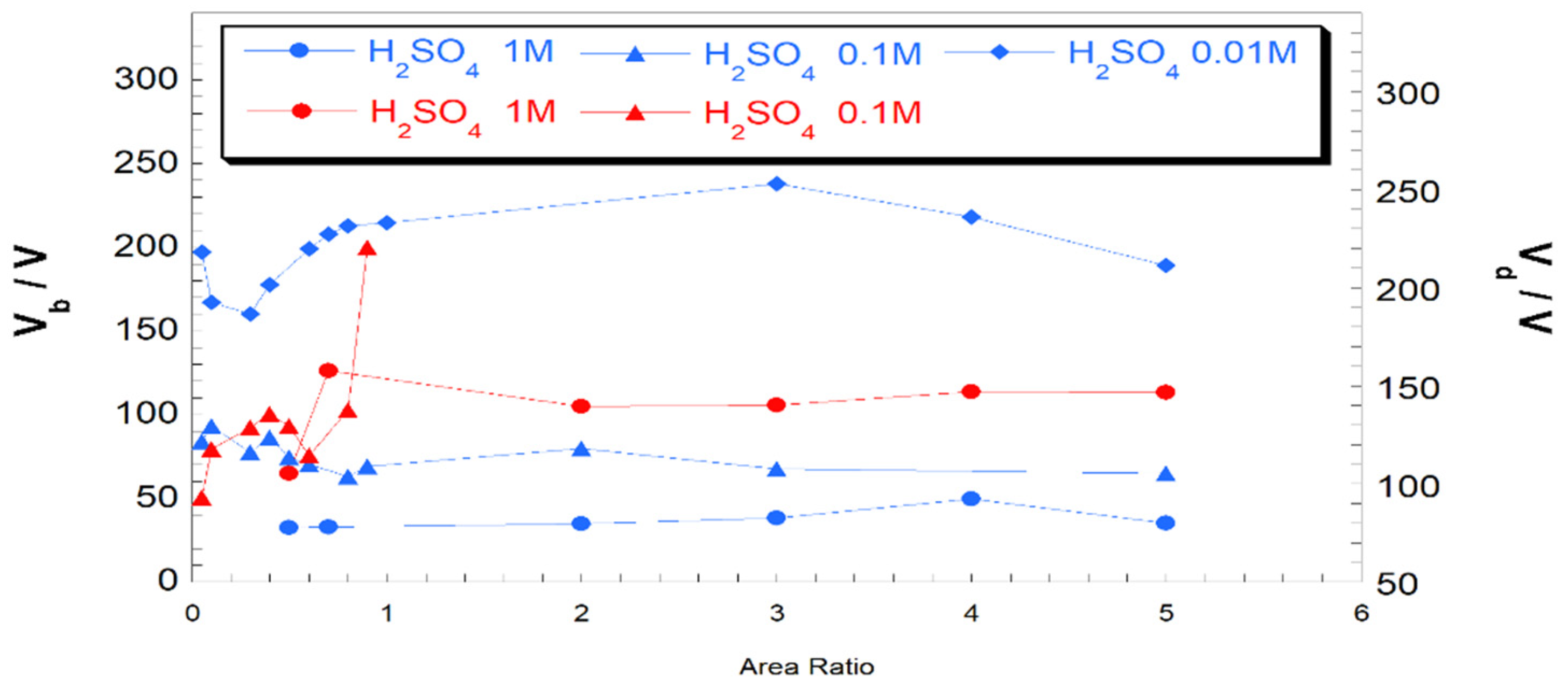
Figure 6 resumes the trend of both VB and VD of H2SO4 (top), KOH (middle top), K2CO3 (middle bottom) and KCl (bottom), respectively. In general, a higher conductivity leads to a lower VB and a to a faster kinetics of plasma production as evidenced for 1 M and 0.1 M H2SO4 and 0.1 M K2CO3 (Figure 6, left column). In the case of 1 M H2SO4, when the ratio of the immersed areas of cathode to anode is lower than 0.5, we were not able to record the voltage values due to the generation a huge plasma that caused severe electric interferences at the electrode surface. The experiments conducted with electrolytes having relatively low conductivity (lower than 40 mS cm−1) did not produce electrolytic plasma and the determination of VB was difficult. In these cases, characteristic curves of a conventional electrolysis are obtained, which (partially) obeys to Ohm’s law, with a linear current-to-voltage trend.
As already evidenced in the former sections, the cathodic plasma is relatively easier to form with respect to anodic plasma. On the other hand, a complete anodic CGDE is formed only for 1 M H2SO4 solutions. For other cases, it could be observed only a faint glow that was insufficient to set a stable plasma. This means that for the occurrence of anodic CGDE a discharge voltage higher than 320 V (our detection limit) is necessary. In both diluted acid (0.01 M H2SO4) and basic (0.01 M KOH) solutions, a dependence of CGDE on the ratio of the cathode-to-anode-immersed areas was observed. In acidic solutions upon increase of the ratio of the cathode-to-anode-immersed areas from 0.2 to 1, a roughly linear increase of VB is evidenced whereas a ratio larger than 1 gives a practically constant value. Both KCl and K2CO3-based solution showed a clear independency of the generation of the cathodic (or anodic) plasma on the ratio of the cathode-to-anode-immersed areas.
2.4. CGDE in Aqueous–Organic Environment: Water/Glycerol Mixture as Case Study
Equations (3)–(8) (vide supra) refer to a series of electrochemical and radical reactions that occur in water for generating electrolytic plasma. Similar reactions occur when an alcohol or more generally an organic hydrogen donor, is added to the aqueous media (Equations (9) and (10)) [41]:
RCH2OH + H● → RC●HOH + H2
RCH2OH + OH● → RC●HOH + H2O
With respect to pure aqueous media, the addition of an organic co-solvent leads to a higher faradaic efficiency for the H2 evolution preceding the glowing discharge. Among different (poly)alcohols, we decided to employ glycerol due to the presence of three alcoholic groups per molecule and the high miscibility in water (this avoids the formation of different phases in the same system). Glycerol/water mixture was considered a meaningful case-study since it mimics the behavior of organic-contaminated wastewater [46,47,48]. In order to do this, we prepared a 0.5 M glycerol solution in deionized water with 0.1 M KCl Such a solution displayed k = 23.2 mS cm−1 (for sake of comparison the conductivity of a 0.1 M aqueous solution of KCl is 25.6 mS cm−1). The slightly lower conductivity could be ascribed to an increase of the viscosity of the solution due to the presence of glycerol. In this context, we limited our analyses on just one supporting electrolyte. Figure 7 shows that the addition of glycerol in the electrolytic solution seems does not influence the evolution of CGDE being both the VB and VD equal to the one experimented in pure water when the nature of the supporting electrolyte was the same and the solution had an analogous conductivity. Furthermore, the ratio of cathode to anode immersed areas is practically irrelevant in the determination of VB. This is not longer the case when VD is analyzed—indeed, plasma does not develop when the electrode area ratio is lower than 0.6 (i.e., for an anode with larger surface area with respect to the cathode) as verified also in case of aqueous electrolytes. This was mainly attributed to the relatively low conductivity of the solution in the adopted conditions of electrode immersion. In fact, plasma evolution at cathode-to-anode area ratios higher than 0.6 is expected also at low levels of conductivity.
3. Materials and Methods
All the reagents used were obtained from Sigma-Aldrich (Saint Louis, MO, USA) and are, respectively: glycerol (assay 86–89%), H2SO4 (assay 95–98%), K2CO3 (assay ≥ 99%), KCl (assay ≥ 99%). Every aqueous solution was prepared using distilled water. The circuital scheme depicted in Figure 8 describes the electronic circuit of the apparatus used to power the electrolysis and the subsequent CGDE. The power supplying system consisted of a current rectifier circuit connected to the laboratory electrical network, and was able to supply a voltage between 0 and 400 V, with a maximum current of 13 A. The circuit consisted of a variable autotransformer (Model Number TDGC2-3KVA, WOSN, Zhejiang, China, 50–60 Hz, 13 A, 3.51 KVA); a Graetz rectifier diode bridge (KBPC-3510, DC Components Co., Ltd., Taichung, Taiwan 400 V, 35A); six capacitors (Ducati Energia S.p.A. Bologna, Italy, 50–60 Hz, 100 μF); two HoldPeak digital multimeters; one resistance, (0.1 Ω, 100 W). The latter element was inserted in order to protect the digital multimeter which was used as an ammeter. This arrangement was motivated by the unavoidable fluctuations of current which were associated with the formation of plasma. In this way, in the frequent cased in which the plasma caused current peaks that could damage the internal resistance of the instrument, the external safety resistance acted as sacrificial element.
The electrochemical cell was made of borosilicate glass (Marbaglass S.n.c., Roma, RM, Italy), and it had the shape of a tube with a ground stopper (also in glass), equipped with a side spout having an approximate diameter of 1 cm. The latter essentially performed two functions: it allowed the gases generated by the electrolysis and the vapor produced by the overheating of the operating electrode to escape out from the reactor. This kept the pressure inside the cell practically constant and equal to the ambient value. On the other hand, it allowed filling the cell with the electrolyte with a Pasteur pipette, once closed with the upper cap (which also acted as a support for the electrode clamps). Such an experimental setup was designed to minimize the parallax error during the preparation operations of each experiment. Indeed, the cell had an indelible linear calibration mark on its external glass, the level of which coincided with the point of attachment of the terminals. Therefore, for each experiment, we could control finely the area of the immersed electrodes. The electrode support clamps were coated with a high-temperature-resistant, insulating and inert resin in order to avoid the shunting of the electrolyte and/or any parasitic contribution to the measured current. A thermometer was used to control the temperature of the solution. A high definition (HD) digital camera, was used to record each experiment and to qualitatively evaluate the behavior of the plasma (if observed) throughout the measurement time and especially during the transition range from the normal electrolysis to CGDE.
For the measurements of the conductivity of the various solutions, a conductivity cell with a cell constant (K) of 10 cm−1 was used. This was connected to a potentiometer/galvanometer source meter Agilent E5262A (Agilent Technologies Ltd., Santa Clara, CA, USA) as a measuring instrument. The potentiometer/galvanometer, in turn, was connected to a computer on which it was installed Nova 1.9 (Metrohm Autolab B.V., Utrecht, NH) as data recording software. The conductivity of the solutions was measured both before and after each experiment in order to highlight any modification in the electronic properties.
Data on the conductivity of KOH and H2SO4 solutions were taken from the literature [49,50] and were not measured directly. This precaution avoided the damage of the experimental setup because of the corrosive power of these two reagents (strong base and strong acid). Each conductivity value is expressed in mS cm−1, while the concentration (c) is expressed as molarity. The ratio between the electrode areas is a pure number, and it is always the relationship between the area of the cathode and the area of the anode immersed in the solution.
Since the conductivity of the solutions varied considerably with the temperature, in each measurement, the cell was equipped with a thermostat set at the plasma-triggering temperature (Ti) measured in the corresponding experiment. Temperatures higher than 80 °C were reached because the evaporation of the aqueous solution under analysis was no longer negligible: if evaporation occurs and the concentration of the electrolyte increased, the conductivity values recorded were overestimated. For this reason, when the electrolyte in the CGDE formation tests reached these values, the reference was made to this limit as the maximum temperature, and it was at this value that the conductivity of the electrolyte was measured.
The electrodes used during the experiments were of two types: rectangular plates in steel (alloy 304), 1 cm wide, 0.4 cm thick and of variable length; cylinders in pure tungsten, with a diameter of 1 mm and variable length. All the electrodes were purchased from A.G. METAL, Civita Castellana (VT) Italy.
The solutions used were: aqueous solutions of H2SO4 (c: 1 M, 0.1 M, 0.01 M); aqueous solutions of K2CO3 (c: 0.1 M, 0.01 M, 0.001 M); aqueous solutions of KOH (c: 0.1 M, 0.01 M, 0.001 M); aqueous solutions of KCl (c: 0.1 M, 0.01 M, 0.001 M); solutions 0.1, 0.001 M of KCl in mixture H2O + C3H8O3 (glycerol).
The reagents were chosen to study CGDE in both acidic, basic and neutral environments, with various cations and anions, in aqueous solutions and, limited to KCl—also in mixed aqueous/organic environment. Glycerol was chosen as an organic compound because of its high miscibility with water, its low cost, its ease of used and handling. Additionally, as mentioned before [5,41], the production of H2 exploiting the non-faradaic effects of CGDE, in H2O and alcohol solutions, was a promising energetic alternative and glycerol, having three OH alcoholic groups, was of great interest for this.
The experimental procedure executed in each test was as follows: for the preparation of the solutions, the hygroscopic salted (KCl, K2CO3) were first dried for one hour in an oven at 105 °C. H2SO4, being liquid, was added with a calibrated pipette. The electrodes were then fixed to the cell terminals: the operator checked the length of the electrodes once they were fixed. Then, the solution was injected into the cell: once the cap of the reactor was closed, the electrolytic solution was fed, by means of a Pasteur pipette, through the lateral spout. After having prepared and filled the electrolytic cell and having activated the digital multimeters, the electronic circuit was closed. The voltage was then slowly increased: initially, the voltage that passed through the cell was still practically zero—and so was the current. Thanks to the knob on the variable autotransformer, the voltage was constantly increased. Then, when possible, the plasma striking occurs as soon as VD was reached, the development of a glow discharge took place. Once this happens, the experiment was interrupted, and the circuit was open for safety. Once the circuit was opened, the cell was opened and a small aliquot of solution was taken from the region next to the active electrode, in order to subsequently determine its conductivity. The temperature reached by the solution was also noted. It was worth mentioning that the electrode did not suffer any irreversible modification during the plasma and the replacement was due to allow a fairer comparison between the different experiments.
4. Conclusions
Throughout this article, we reported on the study of the properties and the optimal conditions necessary for the formation of the glow discharge by contact electrolysis (universally known as contact glow discharge electrolysis (CGDE)), using cheap materials and moderately high currents. These conditions were adopted to verify its applicability at both the household and the industrial level. Regardless of the chemical nature of the electrode, electrolyte or solvent, the development of the plasma glow discharge generates characteristic curves always shows the same shape, with a maximum current value associated with the breakdown voltage (VB) that is of the electrolysis collapse, and a plasma-triggering voltage (VD) that is associated with a sudden current resurgence. From the experiments performed, a clear dependence of the features of CGDE on the conductivity of the solution was found. Indeed, low conductivity values required very high plasma trigger voltages, even higher than 350 V. On the other hand, highly conductive solutions require extremely low potentials that could be reached with a relatively low energy costs. CGDE preferentially develops on the electrode with the highest charge density (usually coupled with the smaller surface area immersed in the electrolytic solution). When the immersed areas of cathode and the anode are the same, CDGE preferably develops at the cathode, as expected from the lower potential needed for the occurrence of the cathodic plasma. Remarkably, the dependence of VB on the difference of the areas of the two immersed electrodes decreases upon increase of electrolyte conductivity. Finally, it was evidenced how the formation of a continuous layer of vapor around the active electrode is a necessary—but not sufficient—condition for the formation of the electrolytic plasma.
Supplementary Materials
The following are available online at https://www.mdpi.com/2073-4344/10/10/1104/s1, Figures S1–S4: VB and VD as a function of solution conductivity. Table S1. List of the more interesting experiments with relative values of VB, VD and Conductivity. Type of electrode, area ratio and electrolytic solution is specified as well. Video S1: Example of plasma formation.
Author Contributions
Conceptualization, G.B.A. and F.D.; methodology, G.B.A. and M.B.; software, G.B.A. and M.B.; validation, M.B., F.D. and D.D.; formal analysis, G.B.A.; investigation, G.B.A. and M.B.; resources, D.D. and F.D.; data curation, G.B.A. and M.B.; writing—original draft preparation, G.B.A. and M.B.; writing—review and editing, F.D. and D.D.; visualization, G.A. and M.B.; supervision, M.B. and D.D.; project administration, F.D. and D.D.; funding acquisition, D.D. All authors have read and agreed to the published version of the manuscript.
Funding
This research was funded by MIUR (Grant Number: PRIN-2017YH9MRK; project title: Novel Multilayered and Micro-Machined Electrode Nano-Architectures for Electrocatalytic Applications (Fuel Cells and Electrolyzers)).
Conflicts of Interest
The authors declare no conflict of interest.
References
- Wüthrich, R.; Mandin, P. Electrochemical discharges-discovery and early applications. Electrochim. Acta 2009, 54, 4031–4035. [Google Scholar] [CrossRef]
- Sengupta, S.K.; Singh, O.P. Contact glow discharge electrolysis: A study of its onset and location. J. Electroanal. Chem. 1991, 301, 189–197. [Google Scholar] [CrossRef]
- Sengupta, S.K.; Srivastava, A.K.; Singh, R. Contact glow discharge electrolysis: A study on its origin in the light of the theory of hydrodynamic instabilities in local solvent vaporisation by Joule heating during electrolysis. J. Electroanal. Chem. 1997, 427, 23–27. [Google Scholar] [CrossRef]
- Sen Gupta, S.K. Contact glow discharge electrolysis: Its origin, plasma diagnostics and non-faradaic chemical effects. Plasma Sources Sci. Technol. 2015, 24, 063001. [Google Scholar] [CrossRef]
- Sen Gupta, S.K.; Singh, R. Cathodic contact glow discharge electrolysis: Its origin and non-faradaic chemical effects. Plasma Sources Sci. Technol. 2017, 26, 15005. [Google Scholar] [CrossRef]
- Yerokhin, A.L.; Nie, X.; Leyland, A.; Matthews, A.; Dowey, S.J. Plasma electrolysis for surface engineering. Surf. Coatings Technol. 1999, 122, 73–93. [Google Scholar] [CrossRef]
- Yerokhin, A.; Mukaeva, V.R.; Parfenov, E.V.; Laugel, N.; Matthews, A. Charge transfer mechanisms underlying contact glow discharge electrolysis. Electrochim. Acta 2019, 312, 441–456. [Google Scholar] [CrossRef]
- Wüthrich, R.; Allagui, A. Building micro and nanosystems with electrochemical discharges. Electrochim. Acta 2010, 55, 8189–8196. [Google Scholar] [CrossRef]
- Saito, G.; Nakasugi, Y.; Akiyama, T. High-speed camera observation of solution plasma during nanoparticles formation. Appl. Phys. Lett. 2014, 104, 83104. [Google Scholar]
- Kareem, T.A.; Kaliani, A.A. Glow discharge plasma electrolysis for nanoparticles synthesis. Ionics 2012, 18, 315–327. [Google Scholar] [CrossRef]
- Tezuka, M.; Iwasaki, M. Aromatic cyanation in contact glow discharge electrolysis of acetonitrile. Thin Solid Films 2002, 407, 169–173. [Google Scholar] [CrossRef]
- Sharma, N.; Diaz, G.; Leal-Quirós, E. Evaluation of contact glow-discharge electrolysis as a viable method for steam generation. Electrochim. Acta 2013, 108, 330–336. [Google Scholar] [CrossRef]
- Sengupta, S.K.; Sandhir, U.; Misra, N. A study on acrylamide polymerization by anodic contact glow-discharge electrolysis: A novel tool. J. Polym. Sci. Part A Polym. Chem. 2001, 39, 1584–1588. [Google Scholar] [CrossRef]
- Hasanah, A.U.; Junior, A.B.; Saksono, N. Latex-starch hybrid synthesis using CGDE method with ethanol addition and air injection latex-starch hybrid synthesis using CGDE method with ethanol addition and air injection. In AIP Conference Proceedings; AIP Publishing LLC.: Melville, NY, USA, 2019; p. 020002. [Google Scholar]
- Gao, J.; Wang, A.; Li, Y.; Fu, Y.; Wu, J.; Wang, Y.; Wang, Y. Synthesis and characterization of superabsorbent composite by using glow discharge electrolysis plasma. React. Funct. Polym. 2008, 68, 1377–1383. [Google Scholar] [CrossRef]
- Liu, Y. Aqueous p-chloronitrobenzene decomposition induced by contact glow discharge electrolysis. J. Hazard. Mater. 2009, 166, 1495–1499. [Google Scholar] [CrossRef]
- Yang, H.; Matsumoto, Y.; Tezuka, M. Exhaustive breakdown of aqueous monochlorophenols by contact glow discharge electrolysis. J. Environ. Sci. 2009, 21, S142–S145. [Google Scholar] [CrossRef]
- Jin, X.; Bai, H.; Wang, F.; Wang, X.; Wang, X.; Ren, H. Plasma degradation of acid orange 7 with contact glow discharge electrolysis. IEEE Trans. Plasma Sci. 2011, 39, 1099–1103. [Google Scholar] [CrossRef]
- Allagui, A.; Brazeau, N.; Alawadhi, H.; Al-momani, F.; Baranova, E.A. Cathodic contact glow discharge electrolysis for the degradation of liquid ammonia solutions. Plasma Process. Polym. 2015, 12, 25–31. [Google Scholar] [CrossRef]
- Jin, X.; Wang, X.; Wang, Y.; Ren, H. Oxidative degradation of amoxicillin in aqueous solution with contact glow discharge electrolysis. Ind. Eng. Chem. Res. 2013, 52, 9726–9730. [Google Scholar] [CrossRef]
- Ramjaun, S.N.; Yuan, R.; Wang, Z.; Liu, J. Degradation of reactive dyes by contact glow discharge electrolysis in the presence of Cl- ions: Kinetics and AOX formation. Electrochim. Acta 2011, 58, 364–371. [Google Scholar] [CrossRef]
- Chen, Y.; Jin, X. Degradation of rhodamine B by contact glow discharge electrolysis with Fe3O4/BiPO4 nanocomposite as heterogeneous catalyst. Electrochim. Acta 2019, 296, 379–386. [Google Scholar] [CrossRef]
- Zhao, C.; Yang, H.; Ju, M.; Zhao, X.; Li, L.; Wang, S.; An, B. Simultaneous degradation of aqueous trichloroacetic acid by the combined action of anodic contact glow discharge electrolysis and normal electrolytic processes at the cathode. Plasma Chem. Plasma Process. 2019, 39, 751–767. [Google Scholar] [CrossRef]
- Jiang, B.; Hu, P.; Zheng, X.; Zheng, J.; Tan, M.; Wu, M.; Xue, Q. Rapid oxidation and immobilization of arsenic by contact glow discharge plasma in acidic solution. Chemosphere 2015, 125, 220–226. [Google Scholar] [CrossRef] [PubMed]
- Wang, X.; Zhou, M.; Jin, X. Application of glow discharge plasma for wastewater treatment. Electrochim. Acta 2012, 83, 501–512. [Google Scholar] [CrossRef]
- Yang, H.; Zhao, X.; Mengen, G.; Tezuka, M.; An, B.; Li, L.; Wang, S.; Ju, M. Defluorination and mineralization of difluorophenols in water by anodic contact glow discharge electrolysis. Plasma Chem. Plasma Process. 2016, 36, 993–1009. [Google Scholar] [CrossRef]
- Gao, J.; Liu, Y.; Yang, W.; Pu, L.; Yu, J.; Lu, Q. Aqueous p-nitrotoluene oxidation induced with direct glow discharge plasma. Cent. Eur. J. Chem. 2005, 3, 377–386. [Google Scholar] [CrossRef] [Green Version]
- Amano, R.; Tezuka, M. Mineralization of alkylbenzenesulfonates in water by means of contact glow discharge electrolysis. Water Res. 2006, 40, 1857–1863. [Google Scholar] [CrossRef]
- Gai, K. Plasma-induced degradation of diphenylamine in aqueous solution. J. Hazard. Mater. 2007, 146, 249–254. [Google Scholar] [CrossRef]
- Gao, J.; Wang, X.; Hu, Z.; Deng, H.; Hou, J.; Lu, X.; Kang, J. Plasma degradation of dyes in water with contact glow discharge electrolysis. Water Res. 2003, 37, 267–272. [Google Scholar] [CrossRef]
- Gao, J.; Hu, Z.; Wang, X.; Hou, J.; Lu, X.; Kang, J. Oxidative degradation of acridine orange induced by plasma with contact glow discharge electrolysis. Thin Solid Films 2001, 390, 154–158. [Google Scholar] [CrossRef]
- Saksono, N.; Seratri, R.T.; Muthia, R.; Bismo, S. Phenol degradation in wastewater with a contact glow discharge electrolysis reactor using a sodium sulfate. Int. J. Technol. 2015, 6, 1153–1163. [Google Scholar]
- Yan, Z.C.; Li, C.; Lin, W.H. Hydrogen generation by glow discharge plasma electrolysis of methanol solutions. Int. J. Hydrogen Energy 2009, 34, 48–55. [Google Scholar] [CrossRef]
- Munegumi, T. Chemical evolution of aminoacetonitrile to glycine under discharge onto primitive hydrosphere: Simulation experiments using glow discharge. Asian J. Chem. 2016, 28, 555–561. [Google Scholar] [CrossRef]
- Sen Gupta, S.K. Contact glow discharge electrolysis: A novel tool for manifold applications. Plasma Chem. Plasma Process. 2017, 37, 897–945. [Google Scholar]
- Parthasarathy, P.; Narayanan, S.K. Effect of hydrothermal carbonization reaction parameters on. Environ. Prog. Sustain. Energy 2014, 33, 676–680. [Google Scholar]
- Allagui, A.; Elwakil, A.S. On the N-shaped conductance and hysteresis behavior of contact glow discharge electrolysis. Electrochim. Acta 2015, 168, 173–177. [Google Scholar]
- Jin, X.; Wang, X.; Yue, J.; Cai, Y.; Zhang, H. The effect of electrolyte constituents on contact glow discharge electrolysis. Electrochim. Acta 2010, 56, 925–928. [Google Scholar]
- Jin, X.L.; Wang, X.Y.; Zhang, H.M.; Xia, Q.; Wei, D.B.; Yue, J.J. Influence of solution conductivity on contact glow discharge electrolysis. Plasma Chem. Plasma Process. 2010, 30, 429–436. [Google Scholar] [CrossRef]
- Sengupta, S.K.; Singh, O.P. Contact glow discharge electrolysis: A study of its chemical yields in aqueous inert-type electrolytes. J. Electroanal. Chem. 1994, 369, 113–120. [Google Scholar]
- Gangal, U.; Srivastava, M.; Sen Gupta, S.K. Scavenging effects of aliphatic alcohols and acetone on H• radicals in anodic contact glow discharge electrolysis: Determination of the primary yield of H• radicals. Plasma Chem. Plasma Process. 2010, 30, 299–309. [Google Scholar]
- Singh, R.; Gangal, U.; Sen Gupta, S.K. Effects of alkaline ferrocyanide on non-faradaic yields of anodic contact glow discharge electrolysis: Determination of the primary yield of OH· radicals. Plasma Chem. Plasma Process. 2012, 32, 609–617. [Google Scholar] [CrossRef]
- Saito, G.; Nakasugi, Y.; Akiyama, T. Generation of solution plasma over a large electrode surface area. J. Appl. Phys. 2015, 118, 23303. [Google Scholar] [CrossRef]
- Allagui, A.; Wüthrich, R. Gas film formation time and gas film life time during electrochemical discharge phenomenon. Electrochim. Acta 2009, 54, 5336–5343. [Google Scholar] [CrossRef]
- Toth, J.R.; Hawtof, R.; Matthiesen, D.; Renner, J.N.; Sankaran, R.M. On the non-faradaic hydrogen gas evolution from electrolytic reactions at the interface of a cathodic atmospheric-pressure microplasma and liquid water surface. J. Electrochem. Soc. 2020, 167, 116504. [Google Scholar] [CrossRef]
- Santibáñez, C.; Varnero, M.T.; Bustamante, M. Residual glycerol from biodiesel Manufacturing, waste or potential source of bioenergy: A review. Chil. J. Agric. Res. 2011, 71, 469–475. [Google Scholar] [CrossRef]
- Dashnau, J.L.; Nucci, N.V.; Sharp, K.A.; Vanderkooi, J.M. Hydrogen bonding and the cryoprotective properties of glycerol/water mixtures. J. Phys. Chem. B 2006, 110, 13670–13677. [Google Scholar] [CrossRef]
- Mouratoglou, E.; Malliou, V.; Makris, D.P. Novel glycerol-based natural eutectic mixtures and their efficiency in the ultrasound-assisted extraction of antioxidant polyphenols from agri-food waste biomass. Waste Biomass Valorization 2016, 7, 1377–1387. [Google Scholar] [CrossRef]
- Darling, H.E. Conductivity of sulfuric acid solutions. J. Chem. Eng. Data 1964, 9, 421–426. [Google Scholar] [CrossRef]
- Gilliam, R.J.; Graydon, J.W.; Kirk, D.W.; Thorpe, S.J. A review of specific conductivities of potassium hydroxide solutions for various concentrations and temperatures. Int. J. Hydrogen Energy 2007, 32, 359–364. [Google Scholar] [CrossRef]
Figure 1.
Individuation of VB and VD in a typical current–voltage characteristic curve of a contact glow discharge electrolysis (CGDE) experiment. From zero to VB voltage, the electrolysis proceeds with the current increasing in a nonlinear fashion as expected for a faradaic regime. This initial portion of the curve is associated with the formation of gas bubbles. Once the VB value is surpassed, the water vapor (formed because of Joule heating) plus the electrolytic gas coalesce to form a layer surrounding the active electrode. This coalescence causes a sudden drop of current intensity (I) for the increase of the electron transfer resistance at electrode–electrolyte interface. When the applied potential Vappl is larger than VD this gaseous layer turns into an electrochemically generated plasma for the occurrence of a local dielectric breakdown.
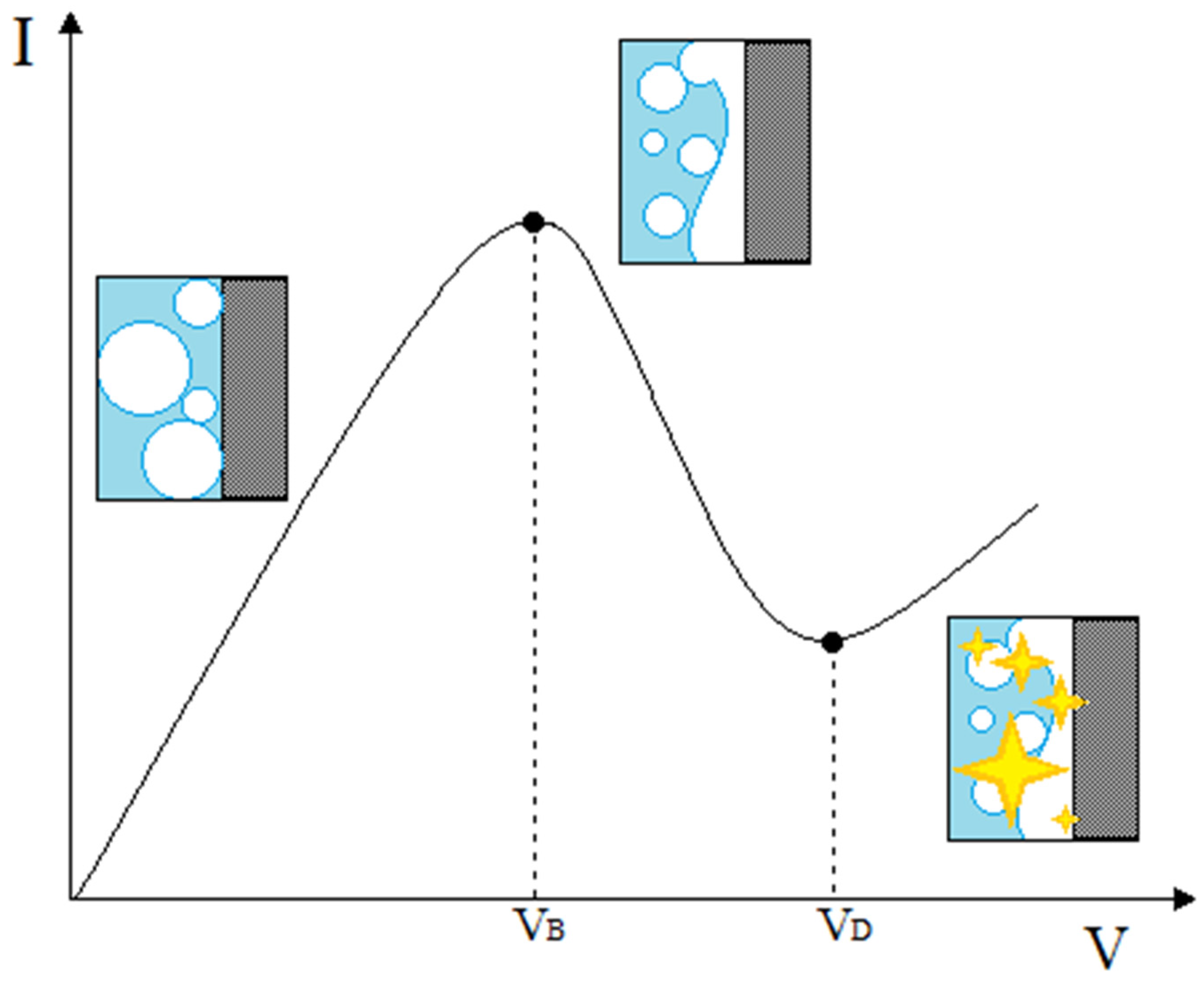
Figure 2.
(top) Breakdown voltage VB and (bottom) VD vs. electrolyte conductivity (mS/cm). In the insets, the colored numbers represent the values of the ratio of the cathode area/anode area for each experiment.
Figure 2.
(top) Breakdown voltage VB and (bottom) VD vs. electrolyte conductivity (mS/cm). In the insets, the colored numbers represent the values of the ratio of the cathode area/anode area for each experiment.
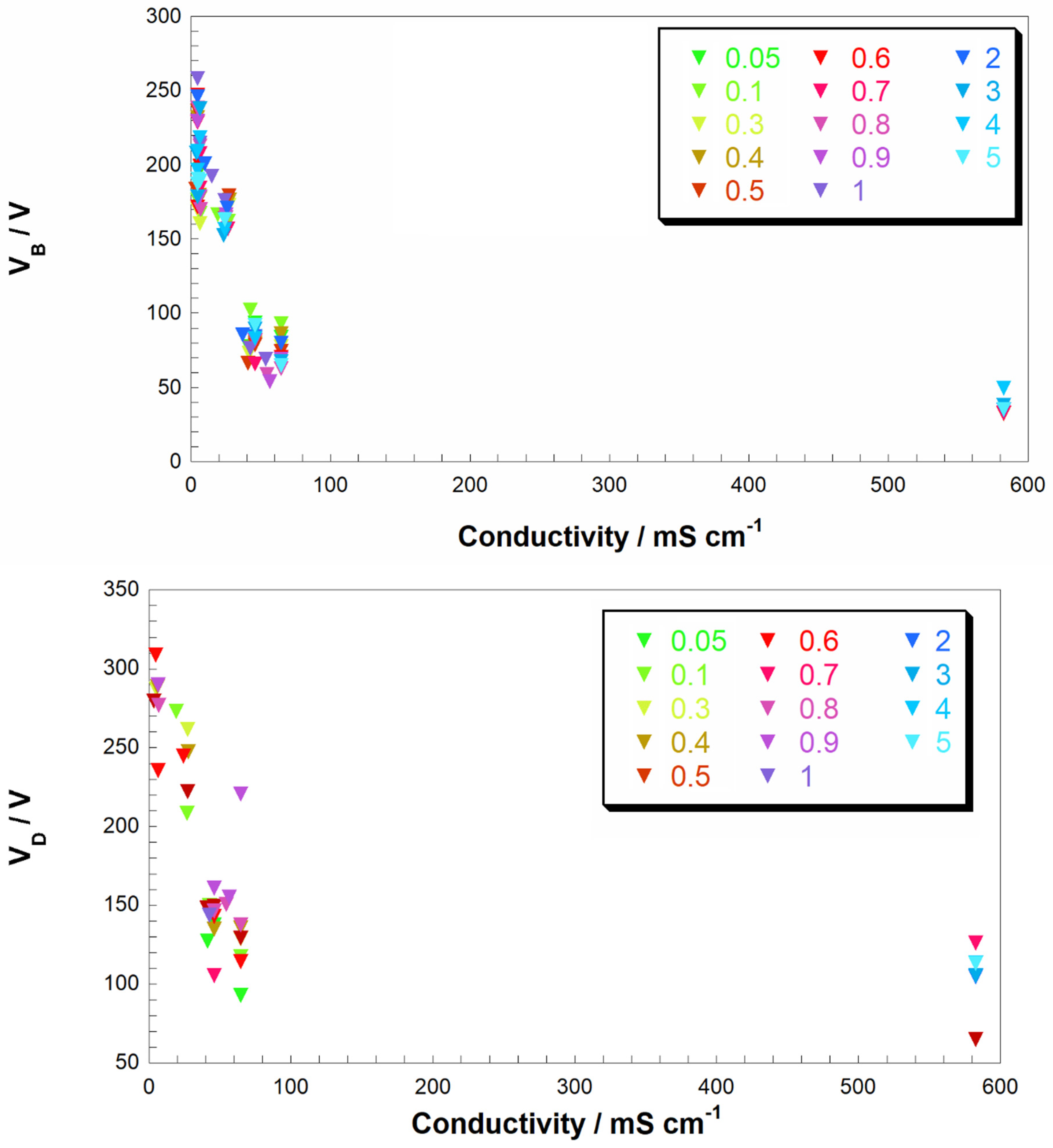
Figure 3.
Breakdown voltage VB as function of electrolyte conductivity when different supporting electrolytes are used. In this series of experiments cathodic plasma is formed. Types of electrolytes: acid (i.e., H2SO4, diamonds), base (KOH, squares), salt with a weak base as anion (K2CO3, triangles) and salt (KCl, circles).

Figure 4.
Breakdown voltage VB (V) vs. conductivity (mS/cm) with anode and cathode areas-ratio that equal to or higher than 1 (case of CGDE active anode). Electrolyte is the same for all experiments.
Figure 4.
Breakdown voltage VB (V) vs. conductivity (mS/cm) with anode and cathode areas-ratio that equal to or higher than 1 (case of CGDE active anode). Electrolyte is the same for all experiments.
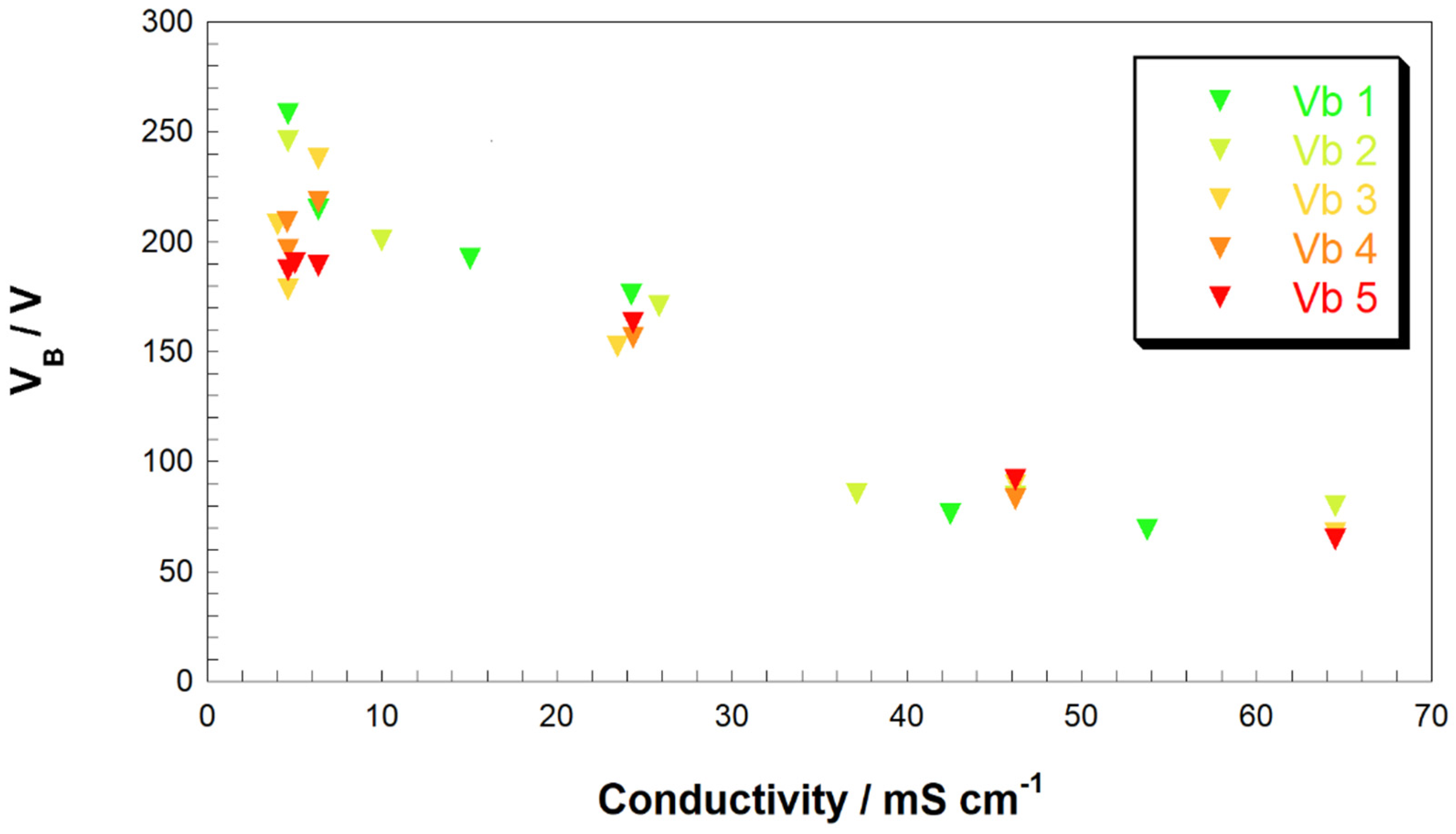
Figure 5.
Discharge voltage, VD, as a function of the conductivity of the solution. Different colors refer to different ratios of cathode-to-anode immersed area. Electrolyte was the same for all experiments.
Figure 5.
Discharge voltage, VD, as a function of the conductivity of the solution. Different colors refer to different ratios of cathode-to-anode immersed area. Electrolyte was the same for all experiments.

Figure 6.
Trend of the characteristic CGDE parameters (VB, left y-axes in blue and VD, right y-axes in red) as a function of the cathode-to-anode ratio with different supporting electrolytes: H2SO4 (top), KOH (middle top), K2CO3 (middle bottom) and KCl (bottom). Different symbols refer to variable electrolyte concentration.


Figure 7.
Breakdown voltage, VB (in green) and discharge voltage, VD (in orange) as a function of the ratio of the cathode-to-anode-immersed areas, with 0.1 M KCl in water (triangles) and glycerol/water mixture (circles).
Figure 7.
Breakdown voltage, VB (in green) and discharge voltage, VD (in orange) as a function of the ratio of the cathode-to-anode-immersed areas, with 0.1 M KCl in water (triangles) and glycerol/water mixture (circles).
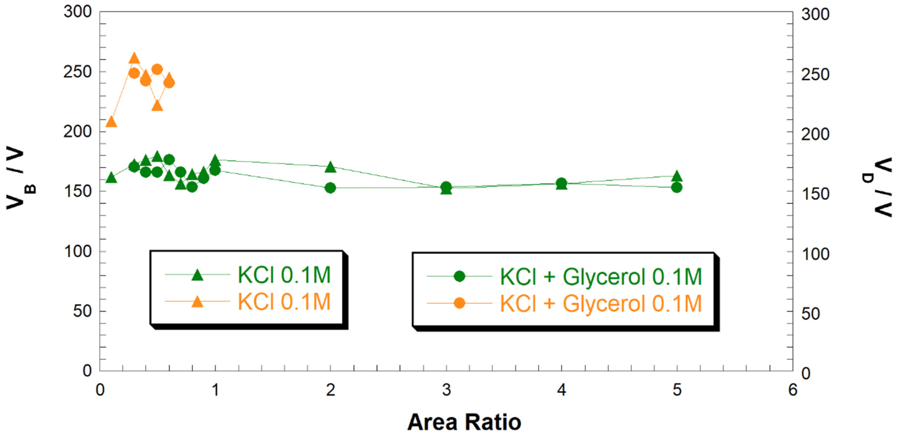
Figure 8.
Diagram of the electrical circuit and the elements constituting the experimental apparatus.
Figure 8.
Diagram of the electrical circuit and the elements constituting the experimental apparatus.

© 2020 by the authors. Licensee MDPI, Basel, Switzerland. This article is an open access article distributed under the terms and conditions of the Creative Commons Attribution (CC BY) license (http://creativecommons.org/licenses/by/4.0/).
Share and Cite
MDPI and ACS Style
Alteri, G.B.; Bonomo, M.; Decker, F.; Dini, D. Contact Glow Discharge Electrolysis: Effect of Electrolyte Conductivity on Discharge Voltage. Catalysts 2020, 10, 1104. https://doi.org/10.3390/catal10101104
AMA Style
Alteri GB, Bonomo M, Decker F, Dini D. Contact Glow Discharge Electrolysis: Effect of Electrolyte Conductivity on Discharge Voltage. Catalysts. 2020; 10(10):1104. https://doi.org/10.3390/catal10101104
Chicago/Turabian StyleAlteri, Giovanni Battista, Matteo Bonomo, Franco Decker, and Danilo Dini. 2020. "Contact Glow Discharge Electrolysis: Effect of Electrolyte Conductivity on Discharge Voltage" Catalysts 10, no. 10: 1104. https://doi.org/10.3390/catal10101104
Note that from the first issue of 2016, this journal uses article numbers instead of page numbers. See further details here.