The Catalytic Performance of Ni-Co/Beta Zeolite Catalysts in Fischer-Tropsch Synthesis

 ,
,  ,
,  , ,
, , 
Abstract
1. Introduction
2. Results and Discussion
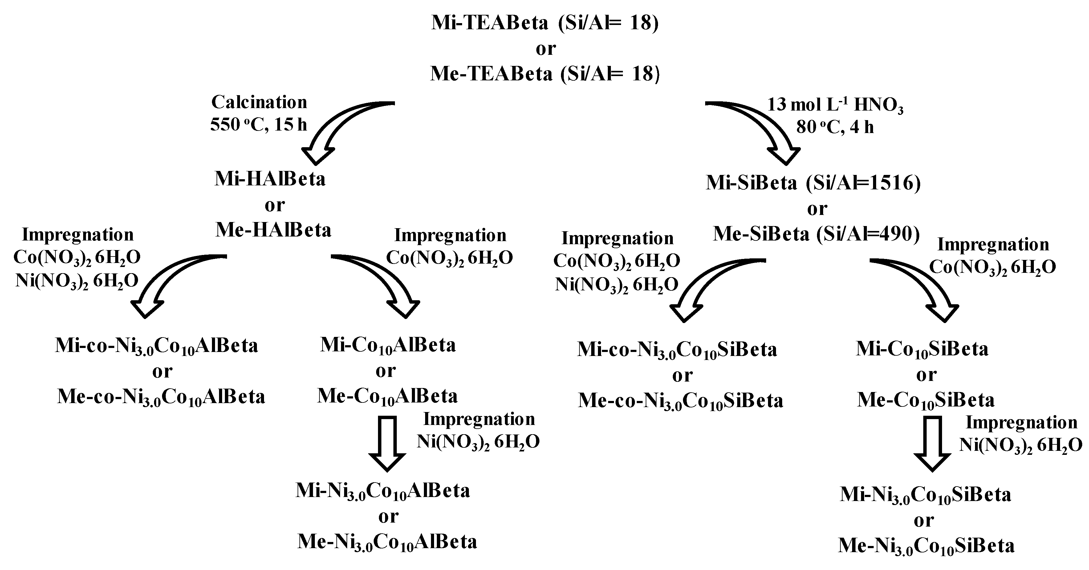
2.1. Preparation of Different Kind of Catalysts
2.2. Characterization with Different Kinds of Techniques
2.2.1. XRD
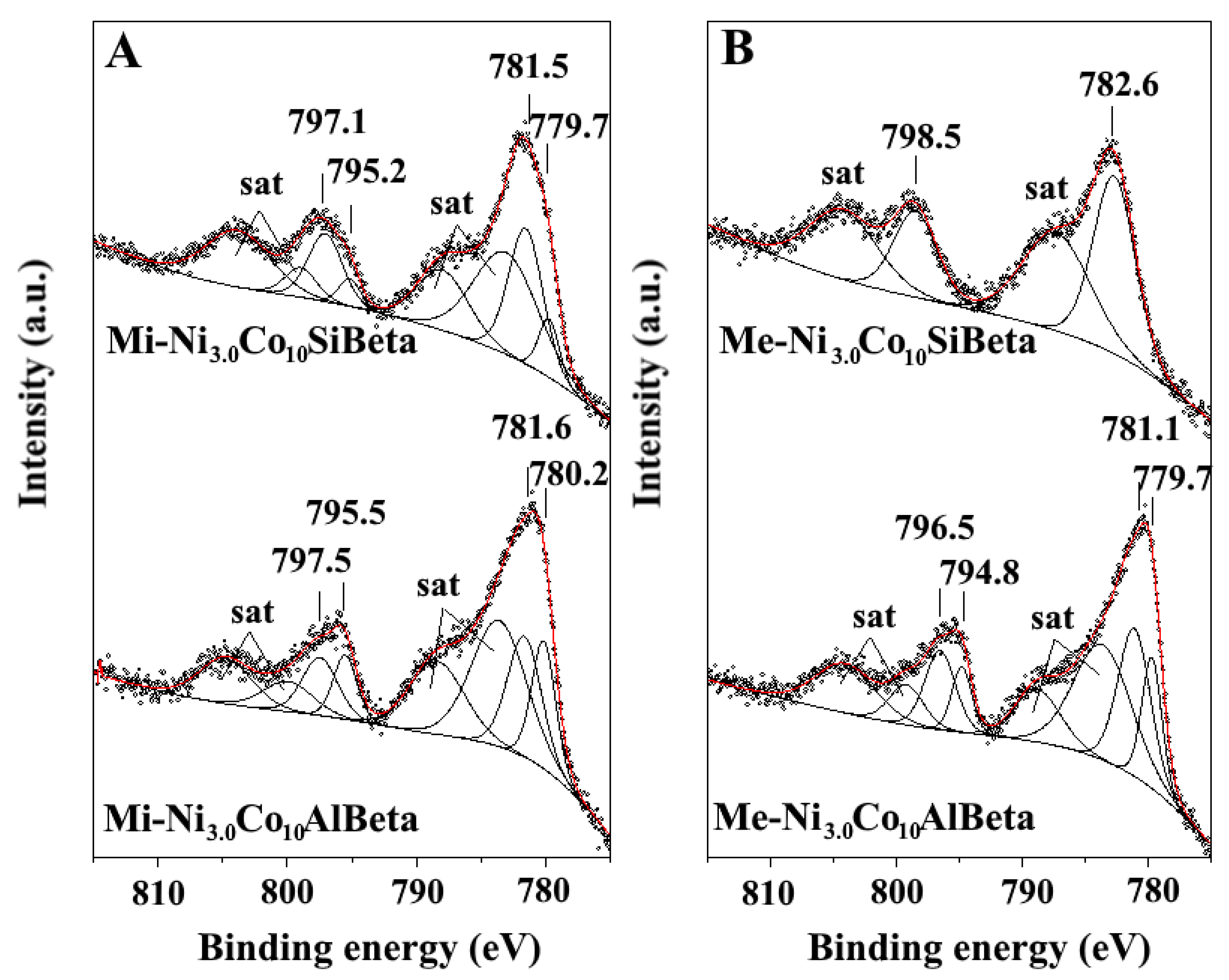
2.2.2. XPS
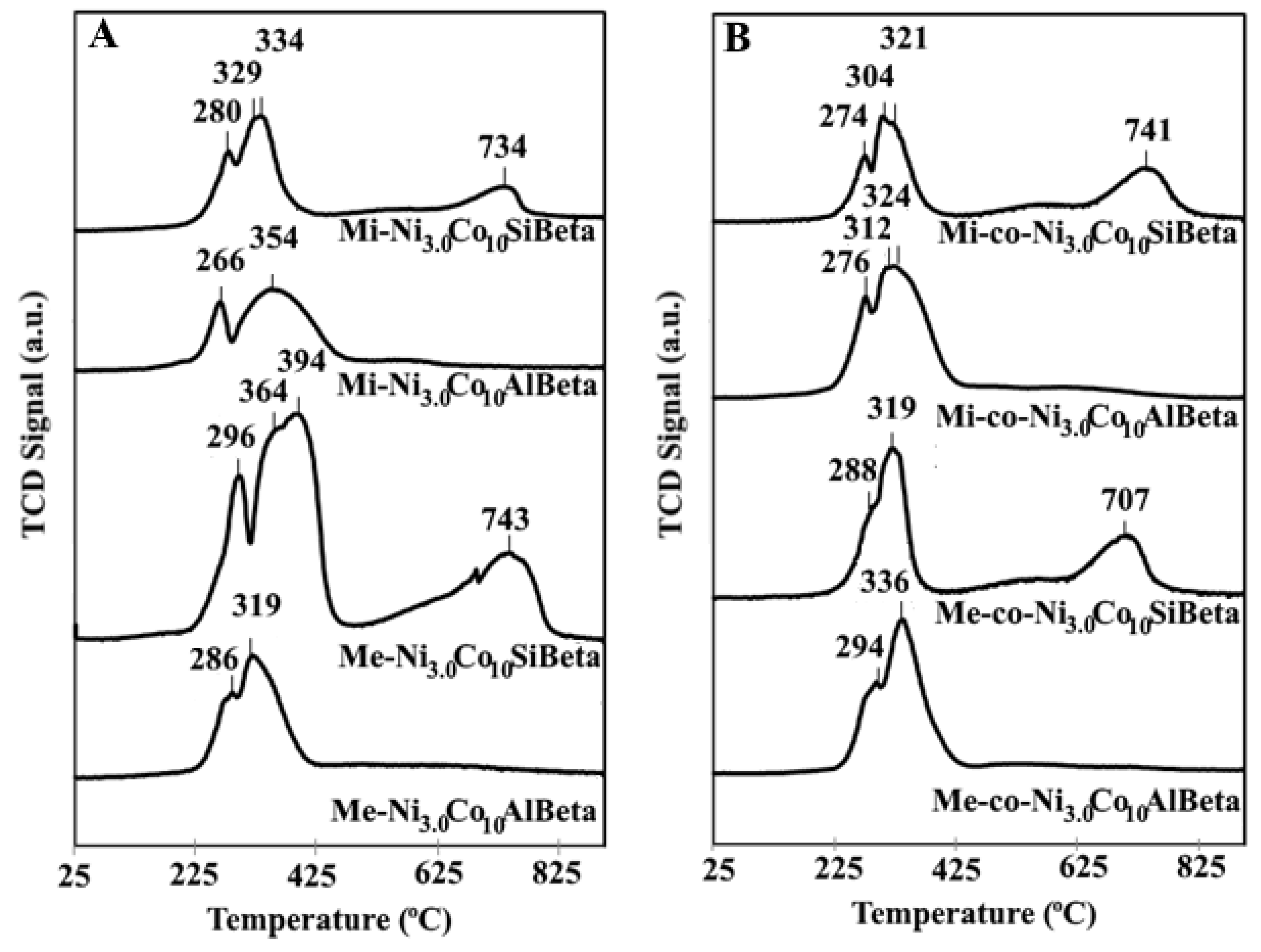
2.2.3. NH3-TPD
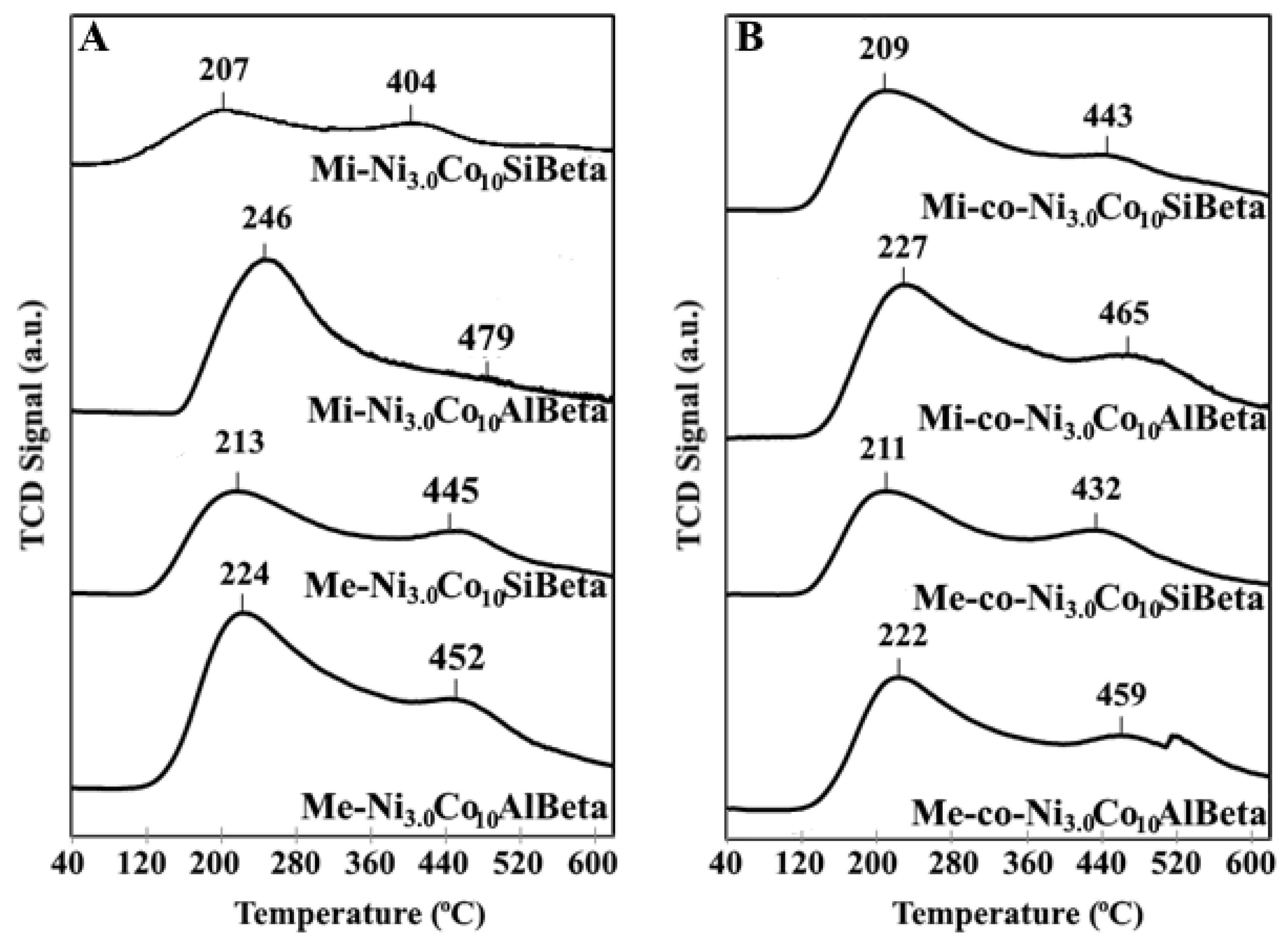
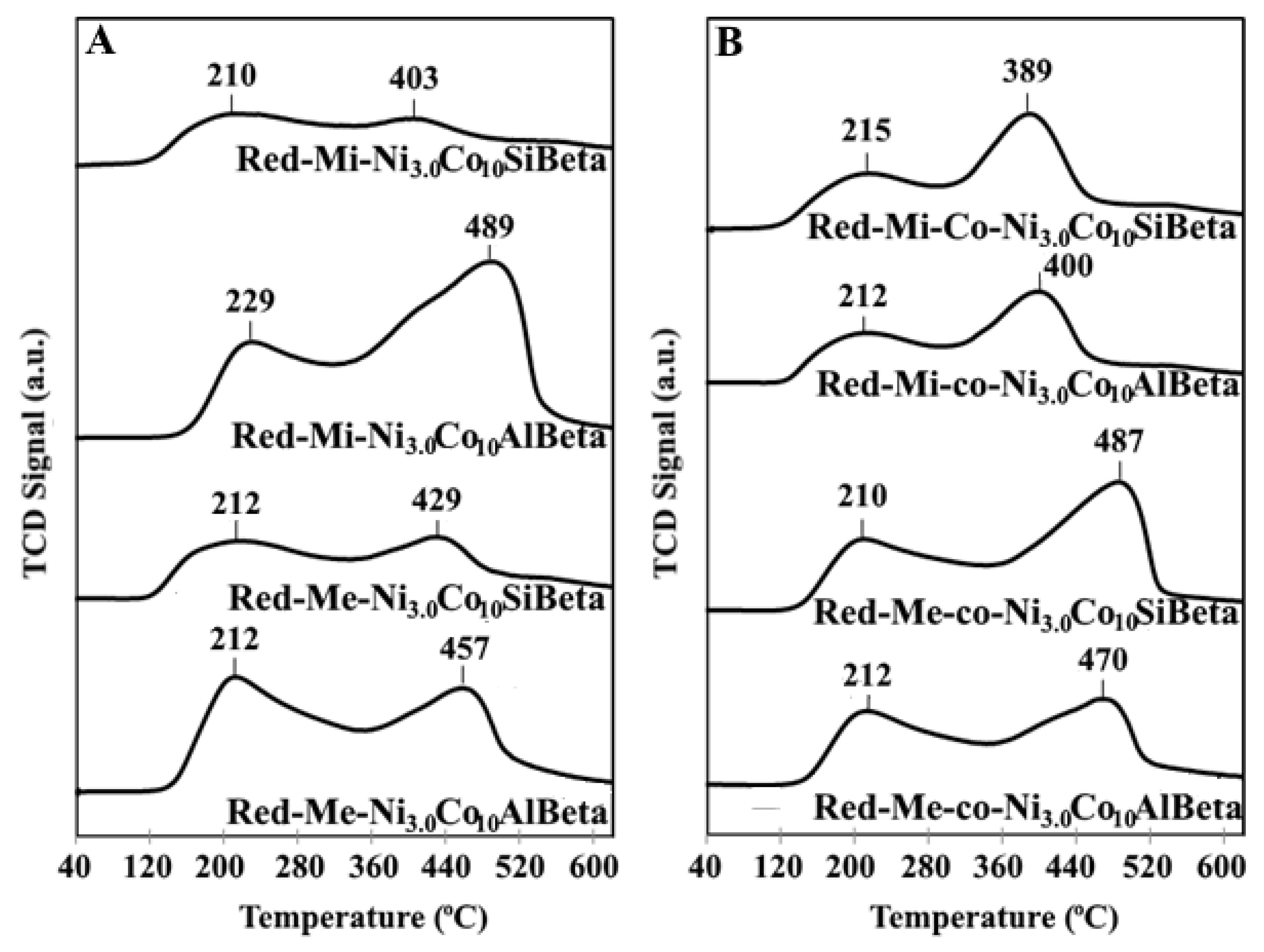
2.2.4. H2-TPR
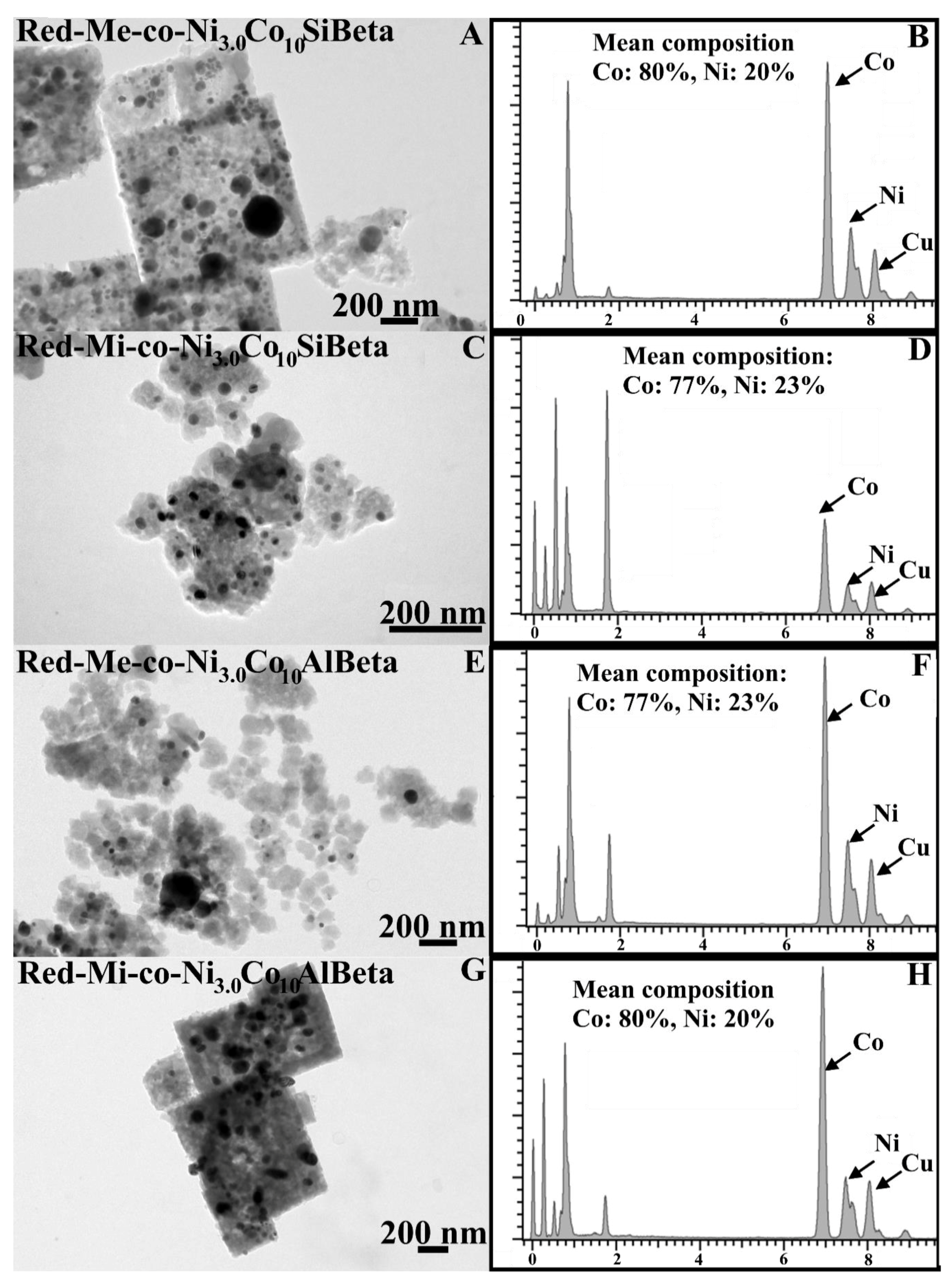
2.2.5. TEM EDX
2.3. Fischer–Tropsch Synthesis
3. Materials and Methods
3.1. Materials Preparation
3.2. Characterization Study
3.2.1. Chemical Analysis
3.2.2. XRD
3.2.3. XPS
3.2.4. NH3-TPD
3.2.5. TPR-H2
3.2.6. TEM-EDS
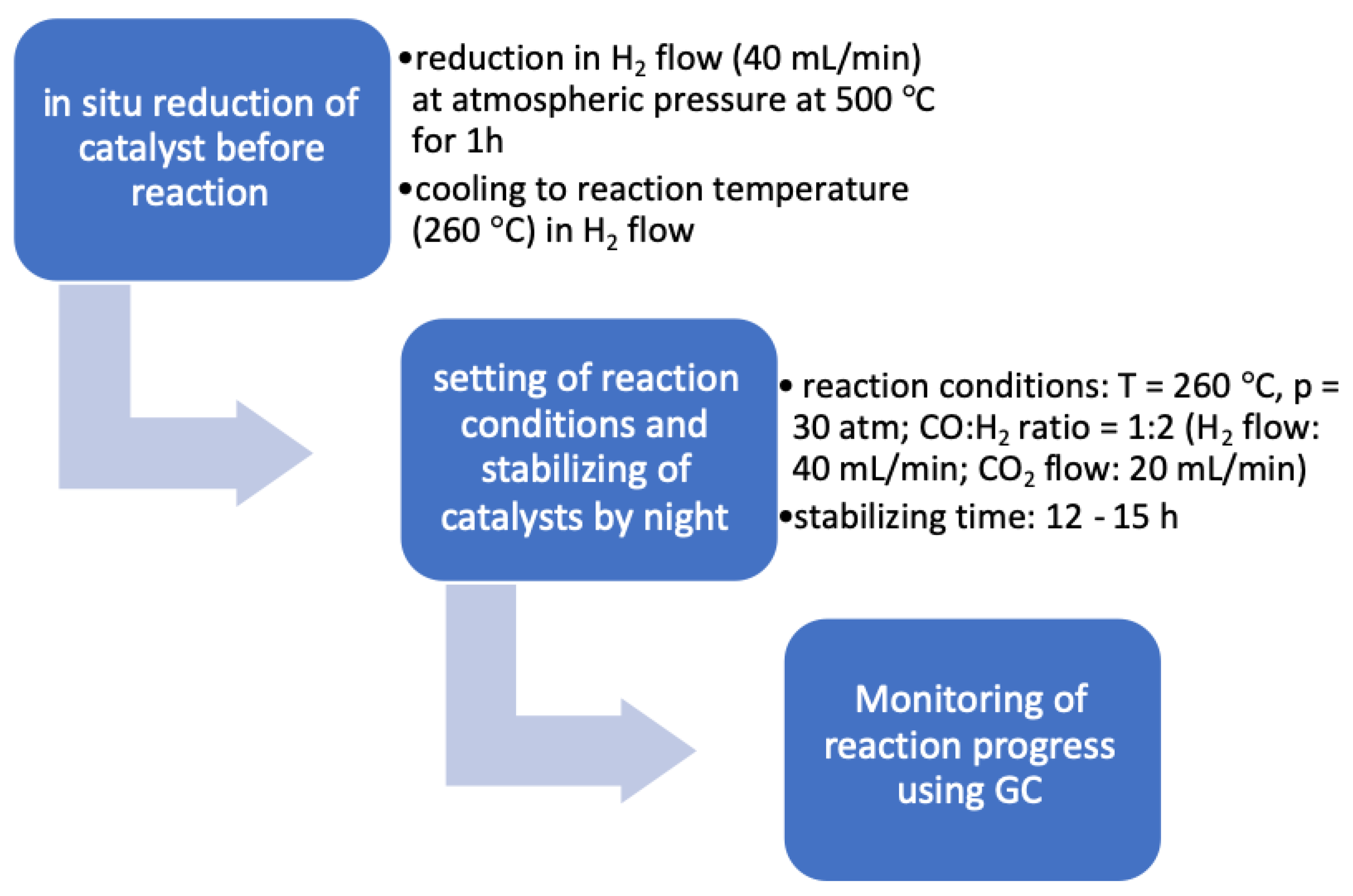
3.3. Catalytic Activity
4. Conclusions
Author Contributions
Funding
Conflicts of Interest
References
- Wu, L.; Li, Z.; Han, D.; Wu, J.; Zhang, D. A preliminary evaluation of ZSM-5/SBA-15 composite supported Co catalysts for Fischer–Tropsch synthesis. Fuel Process. Technol. 2015, 134, 449–455. [Google Scholar] [CrossRef]
- Wang, S.; Yin, Q.; Guo, J.; Ru, B.; Zhu, L. Improved Fischer–Tropsch synthesis for gasoline over Ru, Ni promoted Co/HZSM-5 catalysts. Fuel 2013, 108, 597–603. [Google Scholar] [CrossRef]
- Moodley, D.J.; van de Loosdrecht, J.; Saib, A.M.; Overett, M.J.; Datye, A.K.; Niemantsverdriet, J.W. Carbon deposition as a deactivation mechanism of cobalt-based Fischer–Tropsch synthesis catalysts under realistic conditions. Appl. Catal. A Gen. 2009, 354, 102–110. [Google Scholar] [CrossRef]
- Sartipi, S.; Parashar, K.; Valero-Romero, M.J.; Santos, V.P.; van der Linden, B.; Makkee, M.; Kapteijn, F.; Gascon, J. Hierarchical H-ZSM-5-supported cobalt for the direct synthesis of gasoline-range hydrocarbons from syngas: Advantages, limitations, and mechanistic insight. J. Catal. 2013, 305, 179–190. [Google Scholar] [CrossRef]
- Concepción, P.; López, C.; Martínez, A.; Puntes, V.F. Characterization andatalytic properties of cobalt supported on delaminated ITQ-6 and ITQ-2 zeolites for the Fischer-Tropsch synthesis reaction. J. Catal. 2004, 228, 321–332. [Google Scholar] [CrossRef]
- Jung, J.-S.; Kim, S.W.; Moon, D.J. Fischer–Tropsch Synthesis over cobalt based catalyst supported on different mesoporous silica. Catal. Today 2012, 185, 168–174. [Google Scholar] [CrossRef]
- Najafabadi, A.T.; Khodadadi, A.A.; Parnian, M.J.; Mortazavi, Y. Atomic layer deposited Co/γ-Al2O3 catalyst with enhanced cobalt dispersion and Fischer–Tropsch synthesis activity and selectivity. Appl. Catal A Gen. 2016, 511, 31–46. [Google Scholar] [CrossRef]
- Hajjar, R.; Millot, Y.; Man, P.P.; Che, M.; Dzwigaj, S. Two Kinds of Framework Al Sites Studied in BEA Zeolite by X-ray Diffraction, Fourier Transform Infrared Spectroscopy, NMR Techniques, and V Probe. J. Phys. Chem. C 2008, 112, 20167–20175. [Google Scholar] [CrossRef]
- Baran, R.; Millot, Y.; Onfroy, T.; Krafft, J.M.; Dzwigaj, S. Influence of the nitric acid treatment on Al removal, framework composition and acidity of BEA zeolite investigated by XRD, FTIR and NMR. Microporous Mesoporous Mater. 2012, 163, 122–130. [Google Scholar] [CrossRef]
- Pour, A.N.; Zamani, Y.; Tavasoli, A.; Shahri, S.M.K.; Taheri, S.A. Study on products distribution of iron and iron–zeolite catalysts in Fischer–Tropsch synthesis. Fuel 2008, 87, 2004–2012. [Google Scholar] [CrossRef]
- Martinez, A.; Lopez, C. The influence of ZSM-5 zeolite composition and crystal size on the in situ conversion of Fischer–Tropsch products over hybrid catalysts. Appl. Catal. A Gen. 2005, 294, 251–259. [Google Scholar] [CrossRef]
- Tang, Q.; Wang, Y.; Zhang, Q.; Wan, H. Preparation of metallic cobalt inside NaY zeolite with high catalytic activity in Fischer–Tropsch synthesis. Catal. Commun. 2003, 4, 253–258. [Google Scholar] [CrossRef]
- Liu, Z.W.; Li, X.; Asami, K.; Fujimoto, K. Iso-paraffins synthesis from modified Fischer–Tropsch reaction—Insights into Pd/beta and Pt/beta catalysts. Catal. Today 2005, 104, 41–47. [Google Scholar] [CrossRef]
- Chalupka, K.A.; Casale, S.; Zurawicz, E.; Rynkowski, J.; Dzwigaj, S. The remarkable effect of the preparation procedure on the catalytic activity of CoBEA zeolites in the Fischer–Tropsch synthesis. Microporous Mesoporous Mater. 2015, 211, 9–18. [Google Scholar] [CrossRef]
- Chalupka, K.A.; Maniukiewicz, W.; Mierczynski, P.; Maniecki, T.; Rynkowski, J.; Dzwigaj, S. The catalytic activity of Fe-containing SiBEA zeolites in Fischer–Tropsch synthesis. Catal. Today 2015, 257, 117–121. [Google Scholar] [CrossRef]
- Park, J.-Y.; Lee, Y.-J.; Karandikar, P.R.; Jun, K.-W.; Ha, K.-S.; Park, H.-G. Fischer–Tropsch catalysts deposited with size-controlled Co3O4 nanocrystals: Effect of Co particle size on catalytic activity and stability. Appl. Catal. A Gen. 2012, 411, 15–23. [Google Scholar] [CrossRef]
- Xiong, H.; Zhang, Y.; Liew, K.; Li, J. Catalytic performance of zirconium-modified Co/Al2O3 for Fischer–Tropsch synthesis. J. Mol. Catal. A Chem. 2005, 231, 145–151. [Google Scholar] [CrossRef]
- Ali, S.; Chen, B.; Goodwin, J.G., Jr. Zr Promotion of Co/SiO2 for Fischer-Tropsch Synthesis. J. Catal. 1995, 157, 35–41. [Google Scholar] [CrossRef]
- Xu, D.; Li, W.; Duan, H.; Ge, Q.; Xu, H. Reaction performance and characterization of Co/Al2O3 Fischer–Tropsch catalysts promoted with Pt, Pd and Ru. Catal. Lett. 2005, 102, 229–235. [Google Scholar] [CrossRef]
- Vada, S.; Hoff, A.; Ådnanes, E.; Schanke, D.; Holmen, A. Fischer-Tropsch synthesis on supported cobalt catalysts promoted by platinum and rhenium. Top. Catal. 1995, 2, 155–162. [Google Scholar] [CrossRef]
- Das, T.K.; Jacobs, G.; Patterson, P.M.; Conner, W.A.; Li, J.; Davis, B.H. Fischer–Tropsch synthesis: Characterization and catalytic properties of rhenium promoted cobalt alumina catalysts. Fuel 2003, 82, 805–815. [Google Scholar] [CrossRef]
- Jacobs, G.; Chaney, J.A.; Patterson, P.M.; Das, T.K.; Davis, B.H. Fischer–Tropsch synthesis: Study of the promotion of Re on the reduction property of Co/Al2O3 catalysts by in situ EXAFS/XANES of Co K and Re LIII edges and XPS. Appl. Catal. A Gen. 2004, 264, 203–212. [Google Scholar] [CrossRef]
- Xiong, H.; Zhang, Y.; Liew, K.; Li, J. Ruthenium promotion of Co/SBA-15 catalysts with high cobalt loading for Fischer–Tropsch synthesis. Fuel Process. Technol. 2009, 90, 237–246. [Google Scholar] [CrossRef]
- Rytter, E.; Skagseth, T.H.; Eri, S.; Sjåstad, A.O. Cobalt Fischer−Tropsch Catalysts Using Nickel Promoter as a Rhenium Substitute to Suppress Deactivation. Ing. Eng. Chem. Res. 2010, 49, 4140–4148. [Google Scholar] [CrossRef]
- Sadek, R.; Chalupka, K.A.; Mierczynski, P.; Rynkowski, J.; Millot, Y.; Valentin, L.; Casale, S.; Dzwigaj, S. Fischer-Tropsch reaction on Co-containing microporous and mesoporous Beta zeolite catalysts: The effect of porous size and acidity. Catal. Today 2019. [Google Scholar] [CrossRef]
- Dzwigaj, S.; Che, M. Incorporation of Co(II) in Dealuminated BEA Zeolite at Lattice Tetrahedral Sites Evidenced by XRD, FTIR, Diffuse Reflectance UV−Vis, EPR, and TPR. J. Phys. Chem. B 2006, 110, 12490–12493. [Google Scholar] [CrossRef]
- Mintova, S.; Valtchev, V.; Onfroy, T.; Marichal, C.; Knözinger, H.; Bein, T. Variation of the Si/Al ratio in nanosized zeolite Beta crystals. Microporous Mesoporous Mater. 2006, 90, 237–245. [Google Scholar] [CrossRef]
- Chalupka, K.A.; Jozwiak, W.K.; Rynkowski, J.; Maniukiewicz, W.; Casale, S.; Dzwigaj, S. Partial oxidation of methane on NixAlBEA and NixSiBEA zeolite catalysts: Remarkable effect of preparation procedure and Ni content. Appl. Catal. B Environ. 2014, 146, 227–236. [Google Scholar] [CrossRef]
- Dzwigaj, S.; Janas, J.; Machej, T.; Che, M. Selective catalytic reduction of NO by alcohols on Co- and Fe-Siβ catalysts. Catal. Today 2007, 119, 133–136. [Google Scholar] [CrossRef]
- Fazlollahi, F.; Sarkari, M.; Zare, A.; Mirzaei, A.A.; Atashi, H. Development of a kinetic model for Fischer–Tropsch synthesis over Co/Ni/Al2O3 catalyst. J. Ind. Eng. Chem. 2012, 18, 1223–1232. [Google Scholar] [CrossRef]
- Erdogan, B.; Arbag, H.; Yasyerli, N. SBA-15 supported mesoporous Ni and Co catalysts with high coke resistance for dry reforming of methane. Int. J. Hydrogen Energy 2018, 43, 1396–1405. [Google Scholar] [CrossRef]
- Mosayebi, A.; Abedini, R. Detailed kinetic study of Fischer—Tropsch synthesis for gasoline production over Co-Ni/HZSM-5 nano-structure catalyst. Int. J. Hydrogen Energy 2017, 42, 27013–27023. [Google Scholar] [CrossRef]
- Rodriguez-Gomez, A.; Caballero, A. Bimetallic Ni-Co/SBA-15 catalysts for reforming of ethanol: How cobalt modifies the nickel metal phase and product distribution. Mol. Catal. 2018, 449, 122–130. [Google Scholar] [CrossRef]
- Arbag, H.; Yasyerli, S.; Yasyerli, N.; Dogu, G.; Dogu, T. Enhancement of catalytic performance of Ni based mesoporous alumina by Co incorporation in conversion of biogas to synthesis gas. Appl. Catal. B Environ. 2016, 198, 254–265. [Google Scholar] [CrossRef]
- Boroń, P.; Chmielarz, L.; Gurgul, J.; Łątka, K.; Shishido, T.; Krafft, J.-M.; Dzwigaj, S. BEA zeolite modified with iron as effective catalyst for N2O decomposition and selective reduction of NO with ammonia. Appl. Catal. B Environ. 2013, 138, 434–445. [Google Scholar] [CrossRef]
- Boroń, P.; Chmielarz, L.; Gurgul, J.; Łątka, K.; Gil, B.; Krafft, J.-M.; Dzwigaj, S. The influence of the preparation procedures on the catalytic activity of Fe-BEA zeolites in SCR of NO with ammonia and N2O decomposition. Catal. Today 2014, 235, 210–225. [Google Scholar] [CrossRef]
- Kocemba, I.; Rynkowski, J.; Gurgul, J.; Socha, R.P.; Łątka, K.; Krafft, J.-M.; Dzwigaj, S. Nature of the active sites in CO oxidation on FeSiBEA zeolites. Appl. Catal. A Gen. 2016, 519, 16–26. [Google Scholar] [CrossRef]
- Kumar, M.S.; Schwidder, M.; Grünert, W.; Bentrup, U.; Brückner, A. Selective reduction of NO with Fe-ZSM-5 catalysts of low Fe content: Part II. Assessing the function of different Fe sites by spectroscopic in situ studies. J. Catal. 2006, 239, 173–186. [Google Scholar]
- Arishtirova, K.; Kovacheva, P.; Predoeva, A. Activity and basicity of BaO modified zeolite and zeolite-type catalysts. Appl. Catal. A Gen. 2003, 243, 191–196. [Google Scholar] [CrossRef]
- Kovacheva, P.; Arishtirova, K.; Predoeva, A. Basic zeolite and zeolite-type catalysts for the oxidative methylation of toluene with methane. React. Kinet. Catal. Lett. 2003, 79, 149–155. [Google Scholar] [CrossRef]
- Oleksenko, L.P. Characteristics of Active Site Formation in Co-Containing Catalysts for CO Oxidation on Chemically Different Supports. Theor. Exp. Chem. 2004, 40, 331–336. [Google Scholar] [CrossRef]
- Grünert, W.; Schlögl, R. Photoelectron Spectroscopy of Zeolites. Mol. Sieves 2004, 4, 467–515. [Google Scholar]
- Janas, J.; Gurgul, J.; Socha, R.P.; Dzwigaj, S. Effect of Cu content on the catalytic activity of CuSiBEA zeolite in the SCR of NO by ethanol: Nature of the copper species. Appl. Catal. B Environ. 2009, 91, 217–224. [Google Scholar] [CrossRef]
- Gurgul, J.; Łątka, K.; Hnat, I.; Rynkowski, J.; Dzwigaj, S. Identification of iron species in FeSiBEA by DR UV-vis, XPS and Mössbauer spectroscopy: Influence of Fe content. Microporous Mesoporous Mater. 2013, 168, 1–6. [Google Scholar] [CrossRef]
- Boroń, P.; Chmielarz, L.; Gurgul, J.; Łątka, K.; Gil, B.; Marszałek, B.; Dzwigaj, S. Influence of iron state and acidity of zeolites on the catalytic activity of FeHBEA, FeHZSM-5 and FeHMOR in SCR of NO with NH3 and N2O decomposition. Microporous Mesoporous Mater. 2015, 203, 73–85. [Google Scholar] [CrossRef]
- Kim, J.-G.; Pugmire, D.L.; Battaglia, D.; Langell, M.A. Analysis of the NiCo2O4 spinel surface with Auger and X-ray photoelectron spectroscopy. Appl. Surf. Sci. 2000, 165, 70–84. [Google Scholar] [CrossRef]
- Rodríguez, J.L.; Valenzuela, M.A.; Poznyak, T.; Lartundo, L.; Chairez, I. Reactivity of NiO for 2,4-D degradation with ozone: XPS studies. J. Hazard. Mater. 2013, 262, 472–481. [Google Scholar] [CrossRef]
- NIST X-ray Photoelectron Spectroscopy Database. Available online: http://srdata.nist.gov/xps/ (accessed on 15 September 2012).
- Langell, M.A.; Anderson, M.D.; Carson, G.A.; Peng, L.; Smith, S. Valence-band electronic structure of Co3O4 epitaxy on CoO (100). Phys. Rev. B 1999, 59, 4791–4798. [Google Scholar] [CrossRef]
- Tan, B.J.; Klabunde, K.J.; Sherwood, P.M.A. XPS studies of solvated metal atom dispersed (SMAD) catalysts. Evidence for layered cobalt-manganese particles on alumina and silica. J. Am. Chem. Soc. 1991, 113, 855–861. [Google Scholar] [CrossRef]
- Zhou, Z.; Zhang, Y.; Wang, Z.; Wei, W.; Tang, W.; Shi, J.; Xiong, R. Electronic structure studies of the spinel CoFe2O4 by X-ray photoelectron spectroscopy. Appl. Surf. Sci. 2008, 254, 6972–6975. [Google Scholar] [CrossRef]
- Ivanova, T.; Naumkin, A.; Sidorov, A.; Eremenko, I.; Kiskin, M. X-ray photoelectron spectra and electron structure of polynuclear cobalt complexes. J. Electron. Spectrosc. Relat. Phenom. 2007, 156, 200–203. [Google Scholar] [CrossRef]
- Chen, H.-H.; Shen, S.-C.; Chen, X.; Kawi, S. Selective catalytic reduction of NO over Co/beta-zeolite: Effects of synthesis condition of beta-zeolites, Co precursor, Co loading method and reductant. Appl. Catal. B Environ. 2004, 50, 37–47. [Google Scholar] [CrossRef]
- Janas, J.; Machej, T.; Gurgul, J.; Socha, R.P.; Che, M.; Dzwigaj, S. Effect of Co content on the catalytic activity of CoSiBEA zeolite in the selective catalytic reduction of NO with ethanol: Nature of the cobalt species. Appl. Catal. B Environ. 2007, 75, 239–248. [Google Scholar] [CrossRef]
- Zsoldos, Z.; Vass, G.; Lu, G.; Guczi, L. XPS study on the effects of treatments on Pt2+ and Co2+ exchanged into NaY zeolite. Appl. Surf. Sci. 1994, 78, 467–475. [Google Scholar] [CrossRef]
- Da Cruz, R.S.; Mascarenhas, A.J.S.; Andrade, H.M.C. Co-ZSM-5 catalysts for N2O decomposition. Appl. Catal. B Environ. 1998, 18, 223–231. [Google Scholar] [CrossRef]
- Janas, J.; Gurgul, J.; Socha, R.P.; Kowalska, J.; Nowinska, K.; Shishido, T.; Che, M.; Dzwigaj, S. Influence of the Content and Environment of Chromium in CrSiBEA Zeolites on the Oxidative Dehydrogenation of Propane. J. Phys. Chem. C 2009, 113, 13273–13281. [Google Scholar] [CrossRef]
- Dzwigaj, S.; Janas, J.; Mizera, J.; Gurgul, J.; Socha, R.P.; Che, M. Incorporation of Copper in SiBEA Zeolite as Isolated Lattice Mononuclear Cu(II) Species and its Role in Selective Catalytic Reduction of NO by Ethanol. Catal. Lett. 2008, 126, 36–42. [Google Scholar] [CrossRef]
- Boroń, P.; Chmielarz, L.; Casal, S.; Calers, C.; Krafft, J.-M.; Dzwigaj, S. Effect of Co content on the catalytic activity of CoSiBEA zeolites in N2O decomposition and SCR of NO with ammonia. Catal. Today 2015, 258, 507–517. [Google Scholar] [CrossRef]
- Stanton, A.R.; Iisa, K.; Yung, M.M.; Magrini, K.A. Catalytic fast pyrolysis with metal-modified ZSM-5 catalysts in inert and hydrogen atmospheres. J. Anal. Appl. Pyrol. 2018, 135, 199–208. [Google Scholar] [CrossRef]
- Lim, T.H.; Cho, S.J.; Yang, H.S.; Engelhard, M.H.; Kim, D.H. Effect of Co/Ni ratios in cobalt nickel mixed oxide catalysts on methane combustion. Appl. Catal. A Gen. 2015, 505, 62–69. [Google Scholar] [CrossRef]
- Nieto-Márquez, A.; Lazo, J.C.; Romero, A.; Valverde, J.L. Growth of nitrogen-doped filamentous and spherical carbon over unsupported and Y zeolite supported nickel and cobalt catalysts. Chem. Eng. J. 2008, 144, 518–530. [Google Scholar] [CrossRef]
- Ochoa-Hernández, C.; Yang, Y.; Pizarro, P.; de la Peña O’Shea, V.A.; Coronado, J.M.; Serrano, D.P. Hydrocarbons production through hydrotreating of methyl esters over Ni and Co supported on SBA-15 and Al-SBA-15. Catal. Today 2013, 210, 81–88. [Google Scholar] [CrossRef]
- Sadek, R.; Chalupka, K.A.; Mierczynski, P.; Rynkowski, J.; Gurgul, J.; Dzwigaj, S. Cobalt Based Catalysts Supported on Two Kinds of Beta Zeolite for Application in Fischer-Tropsch Synthesis. Catalysts 2019, 9, 497. [Google Scholar] [CrossRef]
- Shimura, K.; Miyazawa, T.; Hanaoka, T.; Hirata, S. Fischer–Tropsch synthesis over alumina supported bimetallic Co–Ni catalyst: Effect of impregnation sequence and solution. J. Mol. Catal. A Chem. 2015, 407, 15–24. [Google Scholar] [CrossRef]
- Cheng, J.; Hu, P.; Ellis, P.; French, S.; Kelly, G.; Lok, C.M. A DFT study of the chain growth probability in Fischer–Tropsch synthesis. J. Catal. 2008, 257, 221–228. [Google Scholar] [CrossRef]
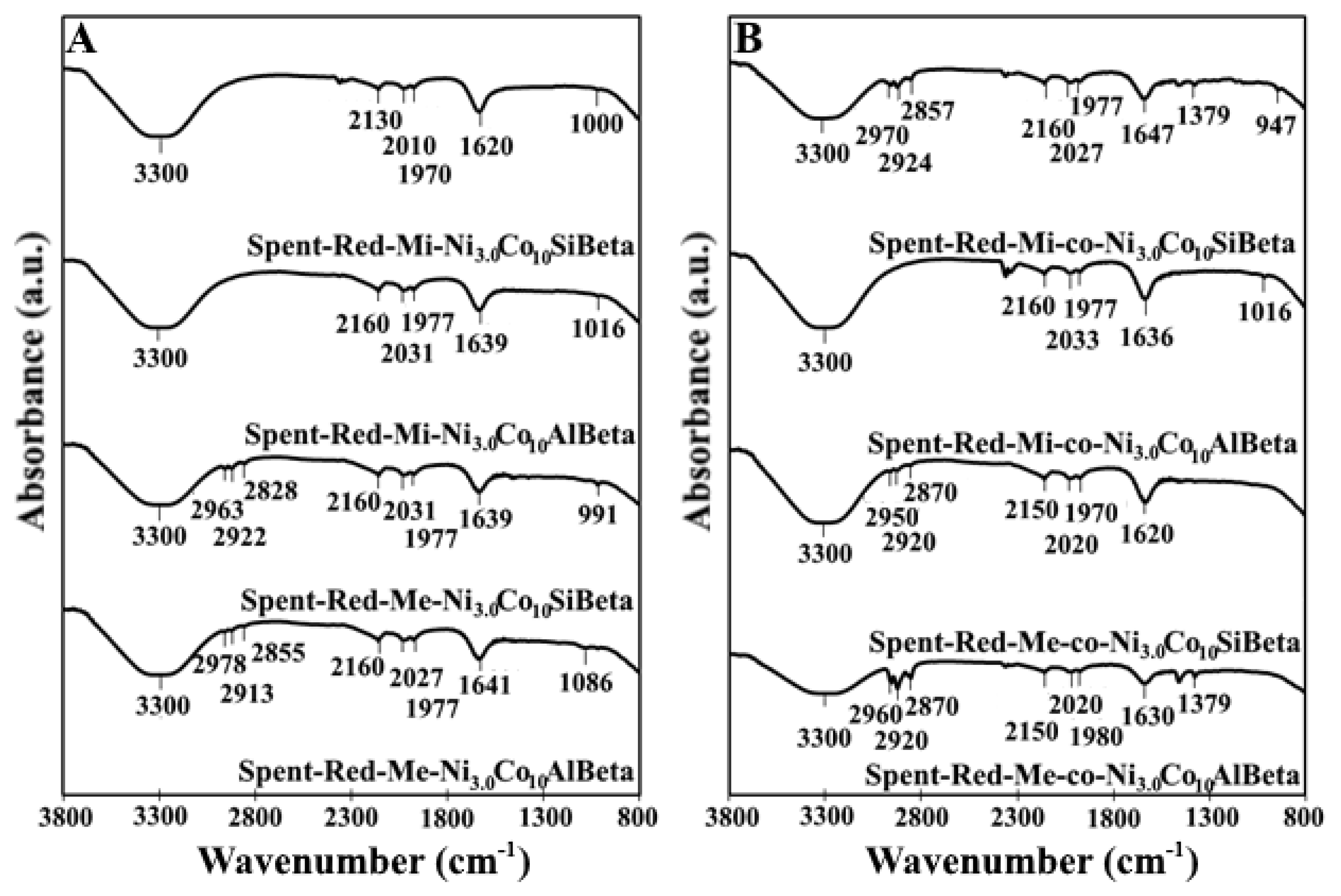
- Socrats, G. Infrared Characteristic Group Frequencies. In Tables and Charts, 2nd ed.; Wiley: Chichester, UK, 1994; pp. 1–249. [Google Scholar]


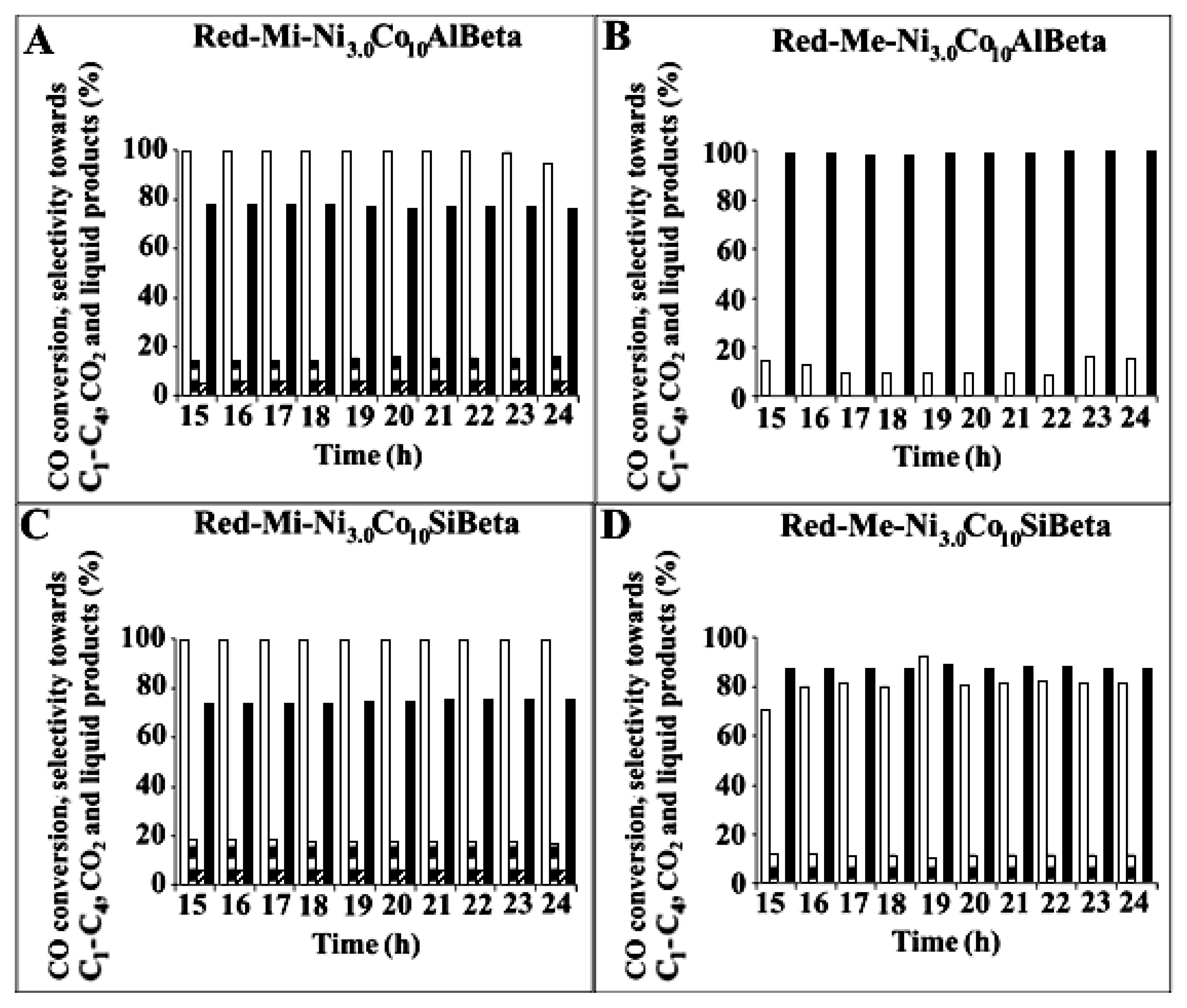
 ) and selectivity to C1-C4 (
 ), CO2 (
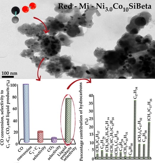
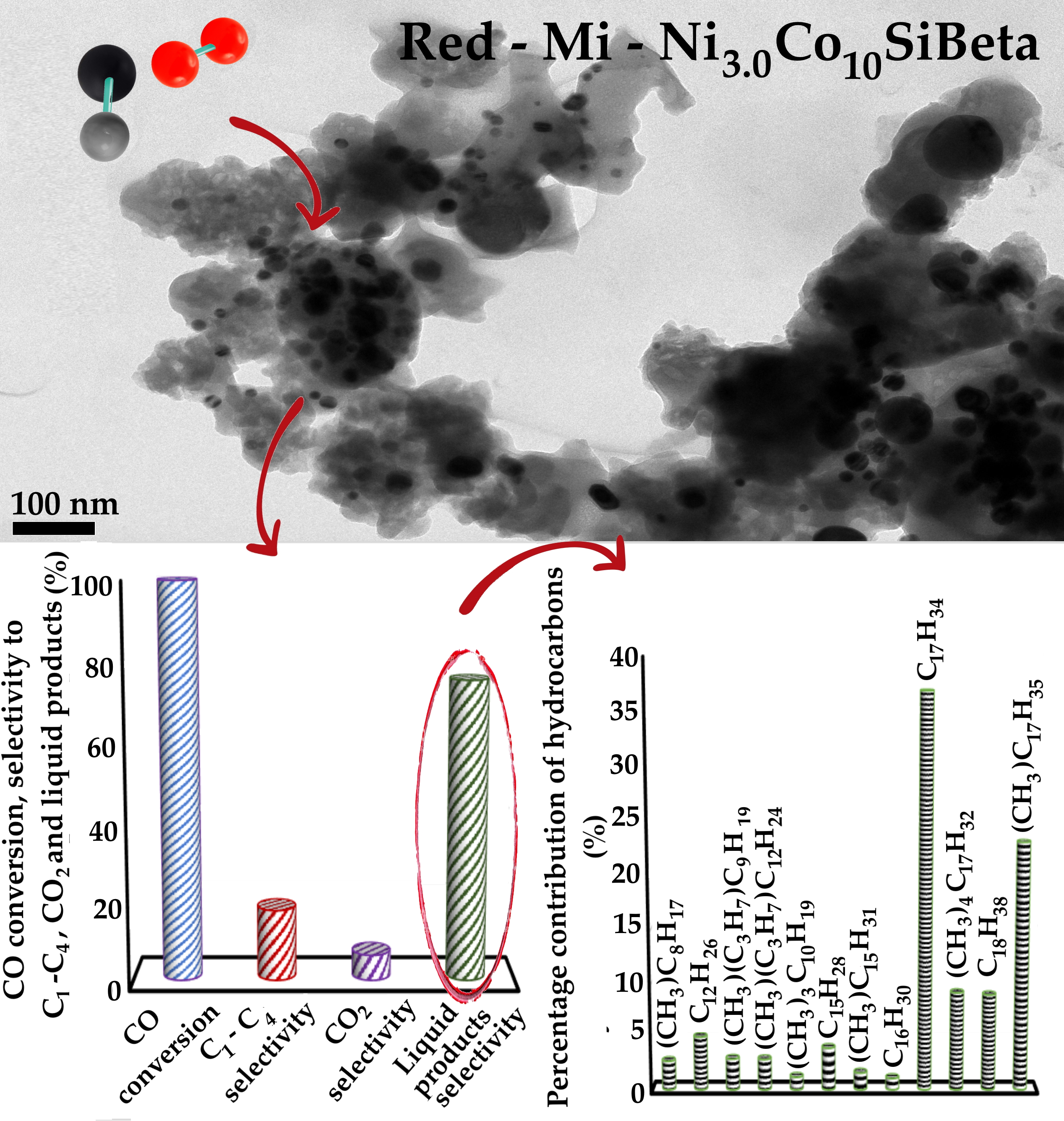
 ) and liquid products (■) after Fischer–Tropsch synthesis (T = 260 °C, p = 30 atm, t = 24 h) over (A) Red-Mi-Ni3.0Co10AlBeta, (B) Red-Me-Ni3.0Co10AlBeta, (C) Red-Mi-Ni3.0Co10SiBeta, (D) Red-Me-Ni3.0Co10SiBeta.
) and selectivity to C1-C4 (), CO2 () and liquid products (■) after Fischer–Tropsch synthesis (T = 260 °C, p = 30 atm, t = 24 h) over (A) Red-Mi-Ni3.0Co10AlBeta, (B) Red-Me-Ni3.0Co10AlBeta, (C) Red-Mi-Ni3.0Co10SiBeta, (D) Red-Me-Ni3.0Co10SiBeta.
) and liquid products (■) after Fischer–Tropsch synthesis (T = 260 °C, p = 30 atm, t = 24 h) over (A) Red-Mi-Ni3.0Co10AlBeta, (B) Red-Me-Ni3.0Co10AlBeta, (C) Red-Mi-Ni3.0Co10SiBeta, (D) Red-Me-Ni3.0Co10SiBeta.
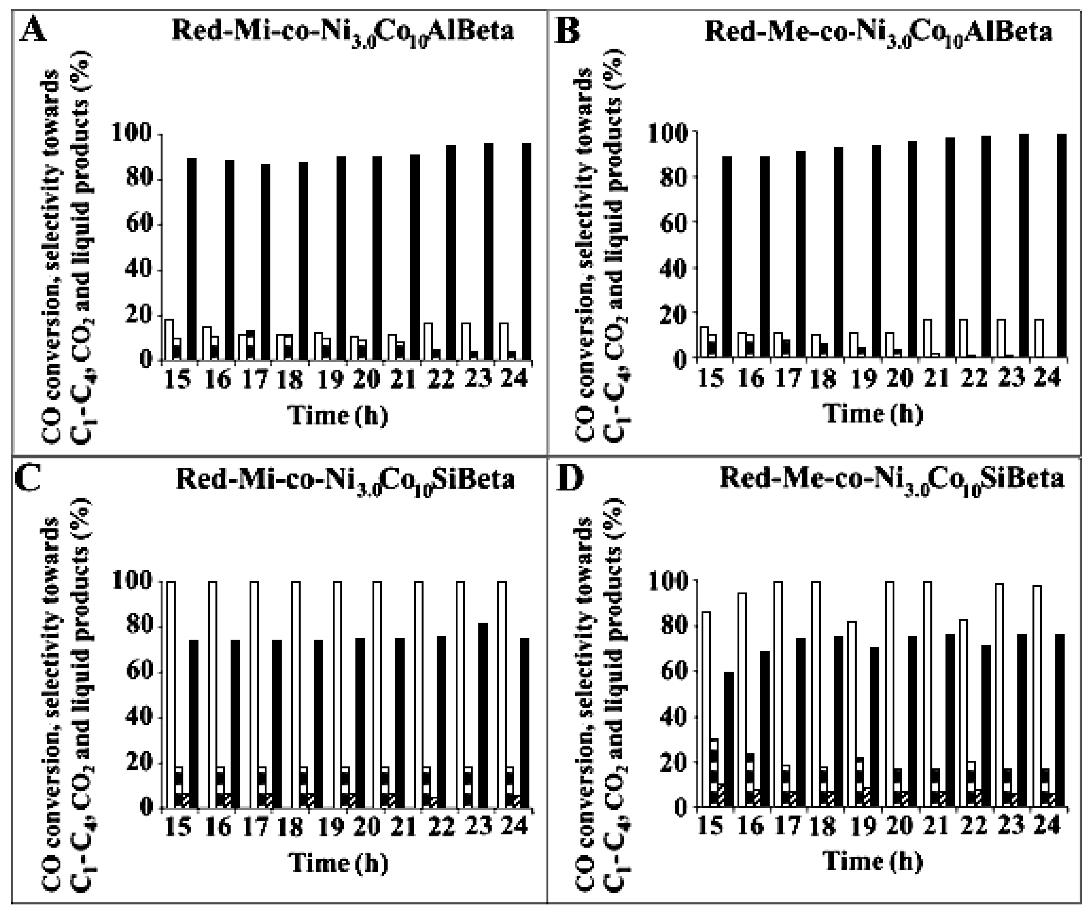
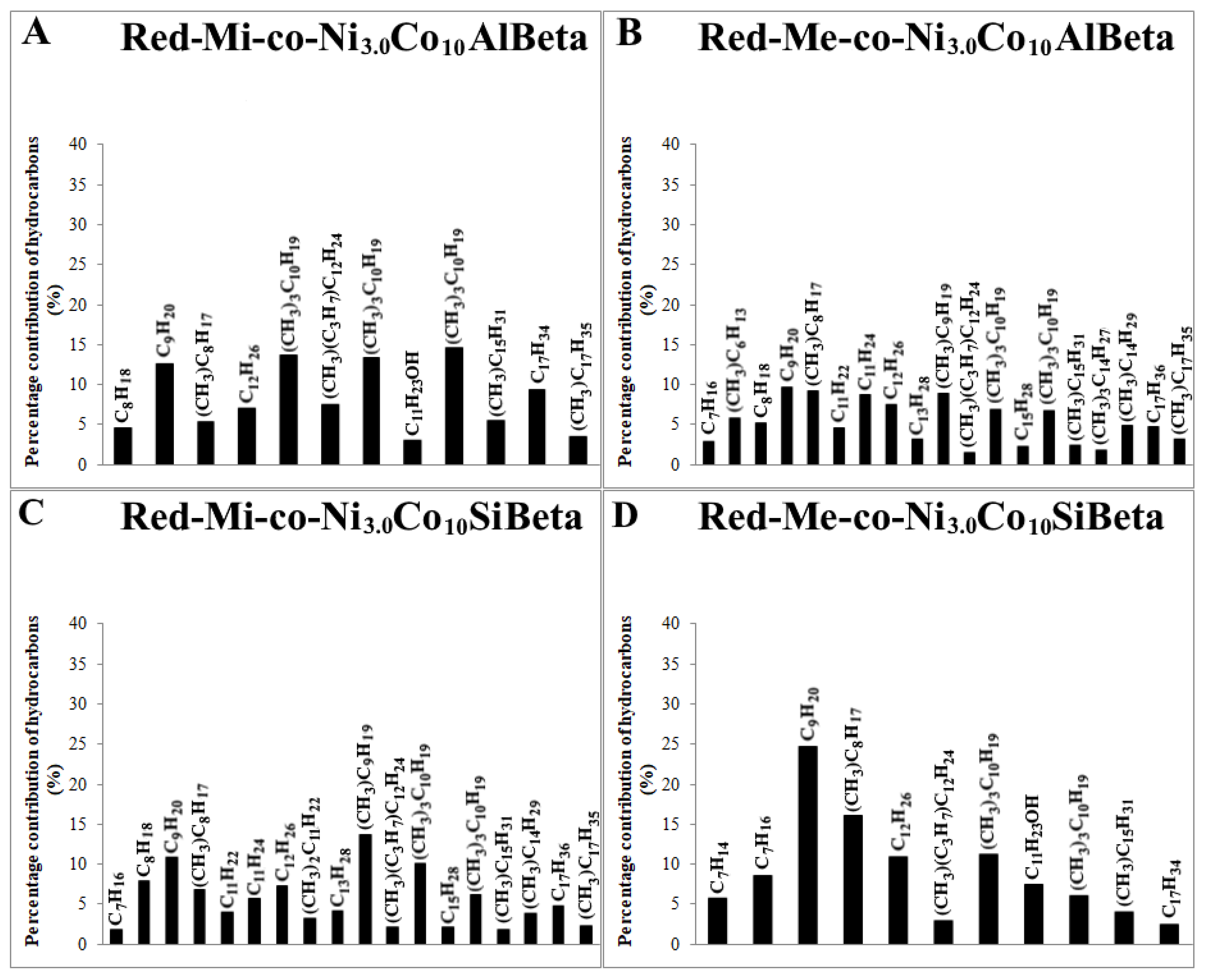
) and selectivity to C1-C4 (), CO2 () and liquid products (■) after Fischer–Tropsch synthesis (T = 260 °C, p = 30 atm, t = 24 h) over (A) Red-Mi-Ni3.0Co10AlBeta, (B) Red-Me-Ni3.0Co10AlBeta, (C) Red-Mi-Ni3.0Co10SiBeta, (D) Red-Me-Ni3.0Co10SiBeta. ) and selectivity to C1-C4 (), CO2 () and liquid products (■) after Fischer-Tropsch synthesis (T = 260 °C, p = 30 atm, t = 24 h) over (A) Red-Mi-co-Ni3.0Co10AlBeta, (B) Red-Me-co-Ni3.0Co10AlBeta, (C) Red-Mi-co-Ni3.0Co10SiBeta, (D) Red-Me-co-Ni3.0Co10SiBeta.
) and selectivity to C1-C4 (), CO2 () and liquid products (■) after Fischer-Tropsch synthesis (T = 260 °C, p = 30 atm, t = 24 h) over (A) Red-Mi-co-Ni3.0Co10AlBeta, (B) Red-Me-co-Ni3.0Co10AlBeta, (C) Red-Mi-co-Ni3.0Co10SiBeta, (D) Red-Me-co-Ni3.0Co10SiBeta.
) and selectivity to C1-C4 (), CO2 () and liquid products (■) after Fischer-Tropsch synthesis (T = 260 °C, p = 30 atm, t = 24 h) over (A) Red-Mi-co-Ni3.0Co10AlBeta, (B) Red-Me-co-Ni3.0Co10AlBeta, (C) Red-Mi-co-Ni3.0Co10SiBeta, (D) Red-Me-co-Ni3.0Co10SiBeta.


| Sample | A | B | ΔSO | Satellites |
|---|---|---|---|---|
| Mi-Ni3.0Co10AlBeta | 780.2 | 781.6 | 15.4–15.8 | 783.6–788.4 |
| - | (42.6) | (57.4) | - | - |
| Mi-Ni3.0Co10SiBeta | 779.7 | 781.5 | 15.4–15.5 | 783.1–788.0 |
| - | (20.5) | (79.5) | - | - |
| Me-Ni3.0Co10AlBeta | 779.7 | 781.0 | 15.1–15.5 | 783.6–788.7 |
| - | (35.3) | (64.7) | - | - |
| Me-Ni3.0Co10SiBeta | - | 782.6 | 15.9 | 787.3 |
| - | - | (100) | - | - |
| Sample | aNH3 (μmol g−1) | Sample * | aNH3 (μmol g−1) * |
|---|---|---|---|
| Mi-Ni3.0Co10AlBeta | 1006 | Mi-HAlBeta | 1459 |
| Red-Mi-Ni3.0Co10AlBeta | 2914 | Mi-Co10AlBeta | 1404 |
| Mi-co-Ni3.0Co10AlBeta | 1586 | Red-Mi-Co10AlBeta | 2555 |
| Red-Mi-co-Ni3.0Co10AlBeta | 2604 | - | - |
| Mi-Ni3.0Co10SiBeta | 590 | Mi-SiBeta | 435 |
| Red-Mi-Ni3.0Co10SiBeta | 1048 | Mi-Co10SiBeta | 1430 |
| Mi-co-Ni3.0Co10SiBeta | 1265 | Red-Mi-Co10SiBeta | 1350 |
| Red-Mi-co-Ni3.0Co10SiBeta | 1986 | - | - |
| Me-Ni3.0Co10AlBeta | 1598 | Me-HAlBeta | 1488 |
| Red-Me-Ni3.0Co10AlBeta | 2179 | Me-Co10AlBeta | 1404 |
| Me-co-Ni3.0Co10AlBeta | 1364 | Red-Me-Co10AlBeta | 2569 |
| Red-Me-co-Ni3.0Co10AlBeta | 2103 | - | - |
| Me-Ni3.0Co10SiBeta | 947 | Me-SiBeta | 419 |
| Red-Me-Ni3.0Co10SiBeta | 1389 | Me-Co10SiBeta | 1358 |
| Me-co-Ni3.0Co10SiBeta | 1161 | Red-Me-Co10SiBeta | 1130 |
| Red-Me-co-Ni3.0Co10SiBeta | 1710 | - | - |
| Sample | CO Conversion (%) | Selectivity Towards (%) | Iso/n-Alkane Ratio | Alcohols/Alkane Ratio | Unsaturated/Alkane Ratio | α C1-C4 | ||
|---|---|---|---|---|---|---|---|---|
| C1-C4 | CO2 | Liquid Products | ||||||
| Red-Mi-Ni3.0Co10AlBeta | 95.19 | 16.58 | 6.72 | 76.70 | 2.26 | 0.26 | 0.74 | 0.86 |
| Red-Mi-co-Ni3.0Co10AlBeta | 17.02 | 4.08 | 0.00 | 95.92 | 2.62 | 0.12 | 0.39 | 0.59 |
| Red-Mi-Ni3.0Co10SiBeta | 99.68 | 17.97 | 6.47 | 75.56 | 3.12 | 0.00 | 2.98 | 0.32 |
| Red-Mi-co-Ni3.0Co10SiBeta | 99.66 | 18.19 | 6.50 | 75.31 | 1.18 | 0.00 | 0.15 | 0.65 |
| Red-Me-Ni3.0Co10AlBeta | 16.45 | 0.00 | 0.00 | 100.00 | 2.44 | 0.29 | 0.21 | 0.53 |
| Red-Me-co-Ni3.0Co10AlBeta | 17.29 | 1.05 | 0.00 | 98.95 | 1.22 | 0.00 | 0.17 | 0.64 |
| Red-Me-Ni3.0Co10SiBeta | 81.46 | 12.38 | 0.00 | 87.62 | 1.58 | 0.16 | 0.48 | 0.84 |
| Red-Me-co-Ni3.0Co10SiBeta | 97.86 | 16.94 | 6.48 | 76.58 | 0.91 | 0.17 | 0.18 | 0.80 |
| Catalyst | Reaction Time (h) | The Total Amount of All Products (Millimole/gcat.) |
|---|---|---|
| Red-Mi-Ni3.0Co10AlBeta | 15 | 0.002 |
| 24 | 1.564 | |
| Red-Mi-co-Ni3.0Co10AlBeta | 15 | 0.31 |
| 24 | 0.28 | |
| Red-Mi-Ni3.0Co10SiBeta | 15 | 1.638 |
| 24 | 1.636 | |
| Red-Mi-co-Ni3.0Co10SiBeta | 15 | 1.528 |
| 24 | 1.636 | |
| Red-Me-Ni3.0Co10AlBeta | 15 | 0.248 |
| 24 | 0.27 | |
| Red-Me-co-Ni3.0Co10AlBeta | 15 | 0.238 |
| 24 | 0.284 | |
| Red-Me-Ni3.0Co10SiBeta | 15 | 1.17 |
| 24 | 1.338 | |
| Red-Me-co-Ni3.0Co10SiBeta | 15 | 1.406 |
| 24 | 1.606 |
© 2020 by the authors. Licensee MDPI, Basel, Switzerland. This article is an open access article distributed under the terms and conditions of the Creative Commons Attribution (CC BY) license (http://creativecommons.org/licenses/by/4.0/).
Share and Cite
Sadek, R.; Chalupka, K.A.; Mierczynski, P.; Maniukiewicz, W.; Rynkowski, J.; Gurgul, J.; Lasoń-Rydel, M.; Casale, S.; Brouri, D.; Dzwigaj, S. The Catalytic Performance of Ni-Co/Beta Zeolite Catalysts in Fischer-Tropsch Synthesis. Catalysts 2020, 10, 112. https://doi.org/10.3390/catal10010112
Sadek R, Chalupka KA, Mierczynski P, Maniukiewicz W, Rynkowski J, Gurgul J, Lasoń-Rydel M, Casale S, Brouri D, Dzwigaj S. The Catalytic Performance of Ni-Co/Beta Zeolite Catalysts in Fischer-Tropsch Synthesis. Catalysts. 2020; 10(1):112. https://doi.org/10.3390/catal10010112
Chicago/Turabian StyleSadek, Renata, Karolina A. Chalupka, Pawel Mierczynski, Waldemar Maniukiewicz, Jacek Rynkowski, Jacek Gurgul, Magdalena Lasoń-Rydel, Sandra Casale, Dalil Brouri, and Stanislaw Dzwigaj. 2020. "The Catalytic Performance of Ni-Co/Beta Zeolite Catalysts in Fischer-Tropsch Synthesis" Catalysts 10, no. 1: 112. https://doi.org/10.3390/catal10010112
APA StyleSadek, R., Chalupka, K. A., Mierczynski, P., Maniukiewicz, W., Rynkowski, J., Gurgul, J., Lasoń-Rydel, M., Casale, S., Brouri, D., & Dzwigaj, S. (2020). The Catalytic Performance of Ni-Co/Beta Zeolite Catalysts in Fischer-Tropsch Synthesis. Catalysts, 10(1), 112. https://doi.org/10.3390/catal10010112