Article

Specification and Verification in Integrated Model of Distributed Systems (IMDS)

by
Wiktor B. Daszczuk
Institute of Computer Science, Warsaw University of Technology, Nowowiejska Str. 15/19, 00-665 Warsaw, Poland
Computers 2018, 7(4), 65; https://doi.org/10.3390/computers7040065
Submission received: 6 November 2018 / Revised: 27 November 2018 / Accepted: 28 November 2018 / Published: 2 December 2018

Abstract

:
Distributed systems, such as the Internet of Things (IoT) and cloud computing, are becoming popular. This requires modeling that reflects the natural characteristics of such systems: the locality of independent components, the autonomy of their decisions, and asynchronous communication. Automated verification of deadlocks and distributed termination supports rapid development. Existing techniques do not reflect some features of distribution. Most formalisms are synchronous and/or use some kind of global state, both of which are unrealistic. No model supports the communication duality that allows the integration of a remote procedure call and client-server paradigm into a single, uniform model. The majority of model checkers refer to total deadlocks. Usually, they do not distinguish between communication deadlocks from resource deadlocks and deadlocks from distributed termination. Some verification mechanisms check partial deadlocks at the expense of restricting the structure of the system being verified. The paper presents an original formalism for the modeling and verification of distributed systems. The Integrated Model of Distributed Systems (IMDS) defines a distributed system as two sets: states and messages, and the relationship of the “actions” between these sets. Communication duality provides projections on servers and on traveling agents, but the uniform specification of the verified system is preserved. General temporal formulas over IMDS, independent of the structure of the verified system, allow automated verification. These formulas distinguish between deadlocks and distributed termination, and between communication deadlocks and resource deadlocks. Partial deadlocks and partial termination can be checked. The Dedan tool was developed using IMDS formalism.

1. Introduction

Overview of the Formalism

The author’s experience with building industrial- and research-distributed systems showed that proper modeling and verification of such systems is crucial for their quality [1]. Parallelism of tasks in a concurrent system creates difficulties caused by a possibly infinite set of their common executions. In the Institute of Computer Science, Warsaw University of Technology, a verification methodology based of original synchronous CSM formalism (Concurrent State Machines [2]) was developed and implemented in COSMA design tool [3,4]. Some behavioral errors and communication errors were identified during verification using COSMA [5,6,7,8].
Modern systems add a new dimension of difficulty to parallelism: independent nodes cooperating in a distributed environment. The level of parallelism is much higher than in centralized systems, and there is no real global state of calculations in such a system. No common variables exist, and the only manner of communication between tasks is message passing over the network. The server cannot even expect that a response to a sent message will ever arrive. Except for tightly-coupled systems with a common bus, messages are passed between servers in an asynchronous way.
Such an environment should be considered in modern systems of grid computing, mobile systems, distributed sensor networks, etc. The Internet of Things (IoT) paradigm was introduced, in which independent, autonomous nodes communicate using simple protocols to agree on their coordinated behavior [9]. On the other hand, the high availability services called “cloud computing” introduced massive parallelism of operations in extremely distributed environments. The specification formalism should follow the natural features of modern distributed systems and their verification:
  • communication duality: the system can be seen as cooperating servers in the client-server paradigm, or as distributed agents traveling through servers in a remote procedure call model, but each system is unified and can only be distributed to cooperating servers or traveling agents;
  • locality of actions performed on the server, which depends only on the local state of the server in a distributed environment, and on messages pending locally;
  • autonomy of decisions: server design determines which messages pending locally will be accepted first, i.e., no order predefined between pending messages is assumed;
  • asynchrony of actions: received messages are pending and waiting for acceptance. If there is no pending message or none of pending messages may be accepted in a current state, the server waits for the appropriate message; on the other hand, pending messages wait for a proper server state;
  • asynchrony of communication: each message is sent along a unidirectional asynchronous channel; the sender does not know when the message will reach the target server and when the reply may be expected (if the calculation provides for a response);
  • variety of behavior features: servers communicate using messages and may fall into a communication deadlock; at the same time, agents flow through these messages, and their deadlock is observed over the resource; distributed termination is another way of processing discontinuation, and should be distinguished from deadlocks;
  • total and partial features: there are total deadlocks/termination, but especially in a distributed environment, there may be situations in which a subset of system components falls into a deadlock or terminates successfully, while other processes continue their work; both total and partial deadlocks/termination should be possible to find;
  • automated verification: the verification should not require any knowledge from the designer of temporal logics or model checking techniques.
The most popular formalisms for modeling distributed systems are mentioned in Section 2.1. The majority of them are synchronous, which requires simultaneous activity or access to global/non-local state, which is unrealistic. Such approaches kill locality, autonomy, and asynchrony. Even asynchronous formalism assumes some ordering of messages on the input of servers (queues or stacks). None of the known modeling techniques supports communication duality.
Many techniques mentioned in Section 2.2 support automated model checking, but for a very limited collection of features, typically total deadlock. The deadlock is typically not distinguishable from termination, because both are discontinuations of processes. Partial deadlock/termination, in which not all processes are involved, can be automatically detected for system with restricted schemes, for example, for purely cyclic systems. None of the methods identify communication deadlocks and resource deadlocks.
The proposed IMDS formalism (Integrated Model of Distributed Systems [10,11]), combined with model checking using general temporal formulas, supports all the listed requirements. It is based on a simple observation that the server in a distributed system, being in a given state, accepts the message and executes the action. This action creates a new state of the server and issues a new message. The input message, together with the output one, are a fragment of the distributed computation called agent. The distributed system is described as a relation of "actions" over finite sets of states and messages, composed in pairs (message, state). A special agent-terminating action does not provide an output message; only a new state is present. A specified system may be projected on servers or on agents, giving two views of a distributed systems: server processes communicating via messages or agent processes communicating via servers’ states. We call it communication duality, giving a server view and agent view of the distributed system.
The author developed a set of general temporal formulas over IMDS, unrelated to the structure of the verified system. These formulas are prepared separately for communication deadlocks in the server view, and resource deadlocks and distributed termination in the agent view. They allow for automated verification at the expense of restricting a set of verified features.
The contributions of this paper are twofold: first, IMDS specification formalism supporting communication duality, locality, autonomy, and asynchrony of modeling; second, an automated verification technique for checking communication deadlocks, resource deadlocks, and distributed termination (both partial and total). The combination of these two techniques allowed for the development of the Dedan specification and verification environment. Dedan allows for automated verification of enumerated features of distributed systems. Multiple student exercised and serious distributed systems were successfully verified using this tool.
The proposed IMDS formalism is a basis for several new ideas and techniques for the specification and verification of distributed systems mentioned in other papers: structural siphon-based deadlock detection in Petri nets equivalent to IMDS, applied to arbitrary shaped systems, dual distributed automata (for servers and for agents) to simulate counterexamples over distributed system components, non-exhaustive partial deadlock detection, timed IMDS specification, and others. They go beyond the scope of the present paper, and therefore, they are addressed in the conclusion.
In Section 2, some other approaches to distributed systems modeling and automated verification are presented. Section 3 introduces the IMDS formalism: the overview, the static description of distributed system’s configuration by states and messages, and the behavior of a distributed system in terms of actions. The semantics of distributed system behavior is introduced as a labeled transition system (LTS [12]) over actions. Deadlock and termination are defined in terms of the LTS. Section 3 is the most important in the paper. IMDS was published earlier, but it was formulated in a different way, which is difficult to understand. Moreover, the experience of using the formalism for three years and the invention of many new ideas based on IMDS strongly influenced the current definition.
The LTS of the verified system is the basis of temporal model checking in the Dedan environment, described in Section 4. Section 5 presents an example of deadlock detection under Dedan. The conclusions and the future directions of IMDS and Dedan development are discussed in Section 6.

2. Related Work

2.1. Asynchrony in Modeling of Distributed Systems

Communication in distributed systems is described in the literature in two basic models which are alternatives to each other. A client-server model [13] shows independent servers, actively cooperating by message passing. The servers change their states based on the messages received. Processes in such a model are identified with the servers.
On the other hand, a distributed system can be described in the Remote Procedure Call (RPC) paradigm, with processes traveling between servers by means of procedure invocations and returns [13]. Multiple processes may be originate from one server and migrate to others, treated passively as shared resources. This model can be extended to processes traveling through servers, without the necessity of returning to the server from which those processes come.
There are several models of parallel execution in computer systems [14]. They can generally be divided into synchronous and asynchronous models [15,16,17]. In synchronous models, cooperating processes (or threads, tasks, and other activities running in parallel) must simultaneously communicate in the required states. Therefore, at least cooperative processes must reconcile their states or, alternatively, take part in the global system state in the required manner. Examples of synchronous formalisms are: LOTOS [18], Büchi automata [19] used for verification of systems using linear temporal logic LTL [20], Zielonka’s automata [21], or Timed Automata [22]. In each of these models, the automata synchronize by common symbols on transitions. In CSP [23] and Uppaal timed automata [24], synchronization is performed by the execution of simultaneous send and receive operations. Synchronous operations on complementary input and output ports in CCS [25] and Occam [26] require the agreement of the processes.
We argue that the above models are inadequate to model-distributed systems, because neither global nor non-local states exist in such systems. Distributed processes cannot agree on their states. The only way to influence the behavior of another server is to send a message to it. On the other hand, receiving a reply does not guarantee that the responding server is still in the reported state in the response. Therefore, asynchronous formalisms in which processes do not agree on common states are more realistic in the modeling of distributed systems [27].
Message Passing Automata (MPA [28]) and Pushdown Distributed Automata (PDA [29]) are really asynchronous because received messages are waiting for acceptance in the given structures: queues or stacks. The locality of the actions is established because the acceptance of the message depends on the local state of the receiving automaton and the locally-stored message: the one waiting for the longest time in the queue or, respectively, for shortest time on a stack. However, in both formalisms, the automata are not fully autonomous because they do not decide locally which message is accepted first (it is decided upon the underlying rule: FIFO or LIFO).
Many modeling environments use one of the distribution paradigms: message passing in the client-server paradigm or RPC paradigm with messages serving as process migration means. Even in asynchronous formalisms, like SDL (Specification and Description Language [30]), Focus [31], Promela [32] or π-calculus [33], communication duality is not expressed.
Summing up, the majority of formalisms are synchronous. Several asynchronous formalisms do not support autonomy because the servers react to the messages according to their arrival sequence (FIFO or LIFO). The autonomy requires that a server choses a message to serve on its own. No formalism provides a duality of communication in a unified formalism (message passing/resource sharing).

2.2. Deadlock and Termination Checking

Intensive testing of computer systems may improve the reliability of software, but it does not guarantee its correctness. In distributed systems, where parallelism is very intense, the reachability space (and a number of possible behaviors) can be huge, and testing does not provide dependability. What’s more, there is no global system state, which further aggravates the possibility of verification. For such systems, formal proof of correctness and formal verification are needed in order to build trusted programs. Formal models are needed to express the properties of distributed systems and their verification [1].
Model checking and other formal methods are widely and successfully used in the verification of computer systems, for example in avionics [34] or NASA projects [35]. Formal verification has even entered into everyday work in industry [36,37]. However, the author’s experience with formal methods showed that the verification procedure should be maximally automatized, allowing designers to check their projects without the help of verification specialists.
Many automatic methods of detecting deadlocks and termination are proposed, but usually they focus on the total features in which all system processes take part. On the other hand, partial features (concerning a subset of processes) can be checked by several methods, but usually in the case of systems with a very restricted structure. Moreover, the proposed methods often do not distinguish deadlock from termination, and do not support communication duality: they are addressed only to communication deadlocks [38] or to resource deadlocks [39].
Model checkers are often equipped with automatic deadlock detection [40], for example in Spin and PathFinder [32,41]. Typically, a deadlock is identified as a state without any outgoing transitions (except for self-loops) [42]. However, the total termination seems to be an analogous state, because system processes have no continuation. In a purely cyclic system, where the termination is not expected, the discontinuation identifies the deadlock. In the case of terminating systems, a total deadlock should be distinguished by formalism from total termination [43].
Model checking is usually used to find total deadlocks, i.e., states in which all processes are waiting, and no progress is possible. Temporal formulas can also be used to check for partial deadlocks in which some processes are involved in a deadlock, but other processes can be continued. Basically, in the case of partial deadlocks, temporal formulas are based on the structure of the model being verified [44]. The disadvantage of this approach is that temporal formulas must be developed individually for each analyzed system, using the characteristics of the model [45].
Some other approaches for detecting partial deadlocks use general temporal formulas (i.e., formulas unrelated to the structure of the model being verified), but such general formulas require that the model has specific properties. The inspect tool [46] is based on runtime model checking, which does not accept cyclic reachability spaces. In pairwise model checking [47], the general temporal formula is used for every pair of mutually-related processes operating in shared memory.
If the system is not terminating (it is cyclical), discontinuation of the process is of course a deadlock [48]. Conversely, the verification method can be attributed only to terminating processes [37]. Some detection methods are used in specific system architectures. For example, the WickedXmas approach uses nodes that communicate through queues [49]. The specific method is designed for tree-like component architectures [50]. Many deadlock detection techniques are addressed only to purely cyclic systems [48,51].
In the context of automatic verification, most methods only identify total deadlocks. They do not differentiate deadlocks from termination. Partial deadlocks are automatically located in a minority of methods, at the expense of limiting the structure of verified systems. None of the methods can distinguish between communication deadlocks and resource deadlocks.

3. Integrated Model of Distributed Systems

3.1. Overview

The author realized that old-fashioned models based on synchronous actions in distinct servers are not suitable for distributed systems. In a distributed system, there is neither a global nor a non-local state; therefore, no coordinated action between two or more servers can be performed synchronously. The server can inform another server about its state and its intentions by means of a message. Then, the server can wait for the response to its request, also passed as a message. Neither synchrony nor common variables exist. Servers operate autonomously, deciding on their individual behavior by watching their local variables, which store server state values and contain locally-pending messages. Asynchrony means that usually the server is waiting for a message or the message is waiting for acceptance of the server. Message passing is also asynchronous, based on sending messages along unidirectional asynchronous channels, and possible responses are passed through separate channels in opposite directions.
The new formalism IMDS (Integrated Model of Distributed Systems) is a closed model of a distributed system, i.e., it models resources and their users: no external influence is accepted. Resources and users are modeled as distributed servers, and computations scattered on servers are modeled as traveling agents. Closed system modeling is a typical basis for verification of synchronization solutions, in particular using the static model checking technique [20], which is used for systems specified in IMDS. The IMDS formalism exploits the natural features of distributed systems, rarely found in other models: locality of servers, autonomy of their decisions and asynchrony of performed actions and communication. The most important feature of IMDS is communication duality, which allows the observation of a uniformly-specified distributed system in one of two perspectives: servers communicating by messages or agents communicating via servers’ states.
The IMDS formalism is founded on a basic observation of the server operation in a distributed environment: the server remains in a state defined by the values of its internal variables (Figure 1a). If an agent message arrives (Figure 1b), it can be accepted, which means the execution of the action invoked by the message. The action is carried out completely in the context of this server, without external intervention. As a result of the execution of the action, the server variables get new values, which means the new server state (Figure 1c). In addition, an agent’s next message is generated. The output message continues the operation of the agent represented by the accepted input message (Figure 1d). This simple scheme of server and agent operation in a distributed environment leads to the definition of IMDS. Two basic sets are defined: states and messages. The set of actions is defined as the relation between input pairs (message, state) and output pairs (next message, next state). We say that the state and message match and the action is enabled or prepared if they match. The system described in IMDS starts from two sets: initial states of all servers and initial messages of all agents.
The special type of action is the agent-terminating action, in which only the new server state is present on output, but no next message is generated (the action does not have the feature presented in Figure 1d).
Note that the diagram shown in Figure 1b–d is just an illustration to give the reader an idea of the action. In IMDS, the execution of the action is instant and indivisible, without any phases shown in the figure.
The distributed system is defined on servers and agents—distributed computations are performed in their context in the system. Messages are passed between servers in the context of individual agents, just as states are replaced by next states in the context of individual servers. This duality is a basis for determining the behavioral characteristics that need to be verified: communication deadlock, resource deadlock, and distributed termination.
The process is the sequence of actions: on the same server (server process) or in the same agent (agent process).
The IMDS formalism was described in previous papers [10,11], but its formulation was completely different. The distributed system was defined there on four sets: servers, values of their states, services offered by them, and agents. Processes were defined as sets of states and messages. This wording is quite complicated and difficult to understand at first. In the current formulation, the basic concepts are states and messages, and processes are defined as sets of actions. The new IMDS definition presented in this article is much more convenient and more understandable for the reader.
In paper [10], the dynamic creation of servers and agents was allowed in actions, but in order to check the models statically, we limit the creation of servers and agents to the start of the system.
In the literature, a process in a distributed system is usually defined as a sequence of server state changes. These changes are internal to the server processes that communicates with other processes via message exchange. It is a classic description of a distributed system, understood by many authors as natural: servers cooperating through messages (a client-server model [13]).
However, a different model is possible: if the process involves a traveling agent, it migrates between the servers and performs the agent calculation steps on different servers. The agent communicates with other traveling agents using server states. Messages are process carriers and are therefore hidden in processes. In this way, the system is described by means of resource sharing instead of message passing. This is similar to the Remote Procedure Call (RPC [13]), but in IMDS, it is generally not necessary for the process to return to the calling server.
The IMDS specification covers the two views in the specification. The behavior of a distributed system is defined in a uniform way as a set of actions. Two views of the system can be extracted from a single action-based specification, simply by grouping its actions. The server view of the system is obtained by grouping the actions of individual servers. Processes are identified with servers and communicate by means of messages (as in the client-server paradigm). The agent view is extruded by grouping actions of individual agents. Processes or agents traveling between servers represent distributed computations (as in the RPC paradigm) called agents. Agents collaborate through shared variables represented by the servers’ states. The author defines as “communication duality” the combining two views—cooperating servers or migrant agents—into a single, uniform specification. The two concepts, i.e., servers and agents, can usually be attributed to observable system elements. For example in automatic vehicle guidance systems described in [52], servers are road segment controllers, while agents are vehicles. In a production cell example [53], servers are device sub-controllers, and agents are identified with metal plates traveling through the cell.
Server states and agent messages are on the input and output of the action. Therefore, intermediate states or messages exist between pairs of subsequent actions. It can be said that the state or message “threads” two successive actions.
If actions in a sequence are threaded by server states, this is the server view. Server states are the carrier of the process, and messages are the means of communication between servers. If the sequence is threaded through messages, it is the agent view. Agent messages are the process carriers, while server states are used to communicate processes. These two views are decompositions showing the aspects of message transfer and resource sharing in a distributed system.
Figure 2 presents an example of a distributed system—a bounded buffer with a capacity K = 2. The system consists of three servers: buffer, producer and consumer, their names: Sbuf, Sprod and Scons, respectively. The Sprod server produces items and sends them to the Sbuf using a put message and receives an ok_put reply message. The Sprod server sometimes does something else, which is modeled by a doSth message sent to itself. The Scons server acts similarly. The Sbuf server receives put and get messages, but accepts put only when the buffer is not full, and accepts get only if the buffer is not empty. We can distinguish two agents representing distributed computations: Aprod—consisting of all messages sent and received by Sprod—and Acons. The server states are red ovals and the agent messages are green contour arrows. Agent messages are marked in italics. System actions are shown as thin black arrows between server states. The figure does not explain which messages are accepted in which states, but it is obvious in such a simple system. For example, an empty buffer (state 0_elem) accepts a put message, changes its state to 1_elem, and generates an ok_put message. In the server view, the system is decomposed into three server processes, each of which groups the actions of a given server. In the agent view, the system is decomposed into two agent processes, each of which groups the actions of a given computation (producing or consuming) called an agent. Initial server states and initial agent messages have bold edges. In the figure (and all subsequent ones), the servers and their states are colored red, while the agents and their messages are colored green. Italic is used for agents and their messages.
The obvious limitation of the modeled system class comes from the IMDS rules: there is exactly one input message and at most one output message of the action. Certain classes of systems are difficult to model: systems with broadcast communication, consumable resources, or pools of dynamically-created processes. However, this is not impossible, because a designer can use a pool of “sleeping” agents that are woken up as needed. This pool must be limited in order to statically verify the systems.

3.2. Basic IMDS Definition

The essence of the IMDS approach is to describe a system by two sets and a binary relation on the Cartesian product of these two sets. The sets are:
P = {p1,p2,…}—finite set of states (of servers)
M = {m1,m2,…}—finite set of messages (of agents)
The action relation Λ is a binary relation on M and P:
Λ ⊂ (M × P) × (M × P).
For the elements of Λ we use the notation λ = ((m,p),(m’,p’))∈Λ.
The execution of an action (requested in a message) changes the state of the server and issues another message by the agent. So, the execution of an action transforms the current state and the pending message into the next state and the next message.
In the action (m,p)Λ(m’,p’) we say that:
  • the pair (m,p) match;
  • (m,p) is the input pair; (m’,p’) is the output pair;
  • the state p is current; the message m is pending (we use also a term current message);
  • p’ is the next state; m’ is the next message.
The definition must be supplemented by the sets of initial states Pini and messages Mini:
PiniP,
MiniM.
In the example of the system presented in Figure 2, the sets and the relation are:
P
{p_neutral, produce, c_neutral, consume, 0_elem, 1_elem, 2_elem},
M
{p_doSth, put, ok_put, c_doSth, get, ok_get},
Λ
{((p_doSth, p_neutral),(p_doSth, p_neutral)), ((p_doSth, p_neutral),(put, produce)), ((ok_put, produce),(p_doSth, p_neutral)), ((put, 0_elem),(ok_put, 1_elem)), ((put, 1_elem),(ok_put, 2_elem)), ((c_doSth, c_neutral),(c_doSth, c_neutral)), ((c_doSth, c_neutral),(get, consume)), ((ok_get, consume),(c_doSth, c_neutral)), ((get, 1_elem),(ok_get, 0_elem)), ((get, 2_elem),(ok_get, 1_elem))},
Pini
{p_neutral, c_neutral, 0_elem},
Mini
{p_doSth, c_doSth}.
The equal names of states and messages used in more than one server are preceded by “p_” for producer and by “c_” for consumer.

3.3. IMDS System Behavior

The behavior of a system described in IMDS is represented by a Labeled Transition Systems (LTS [12]), i.e., a rooted labeled directed graph.
For LTS representing the behavior of an IMDS system, the nodes are system configurations (the term “state” is reserved for elements of the set P) (sets of current states and pending messages). The root is the initial configuration Tini. The set of labels is the set of actions Λ of the system. The servers start with Pini and the agents start with Mini; therefore, the initial configuration is a union of them. The set of directed arcs is determined by the actions, which convert their input configurations to their output configurations as follows:
λΛ λ = ((m,p),(m’,p’)); Tinp(λ)⊃{m,p} ⇒ Tout(λ) = Tinp(λ)\{m,p}∪{m’,p’}.
TPM-configuration,
Tini = PiniMini-initial configuration.
LTS = <N,n0,W>,
where:
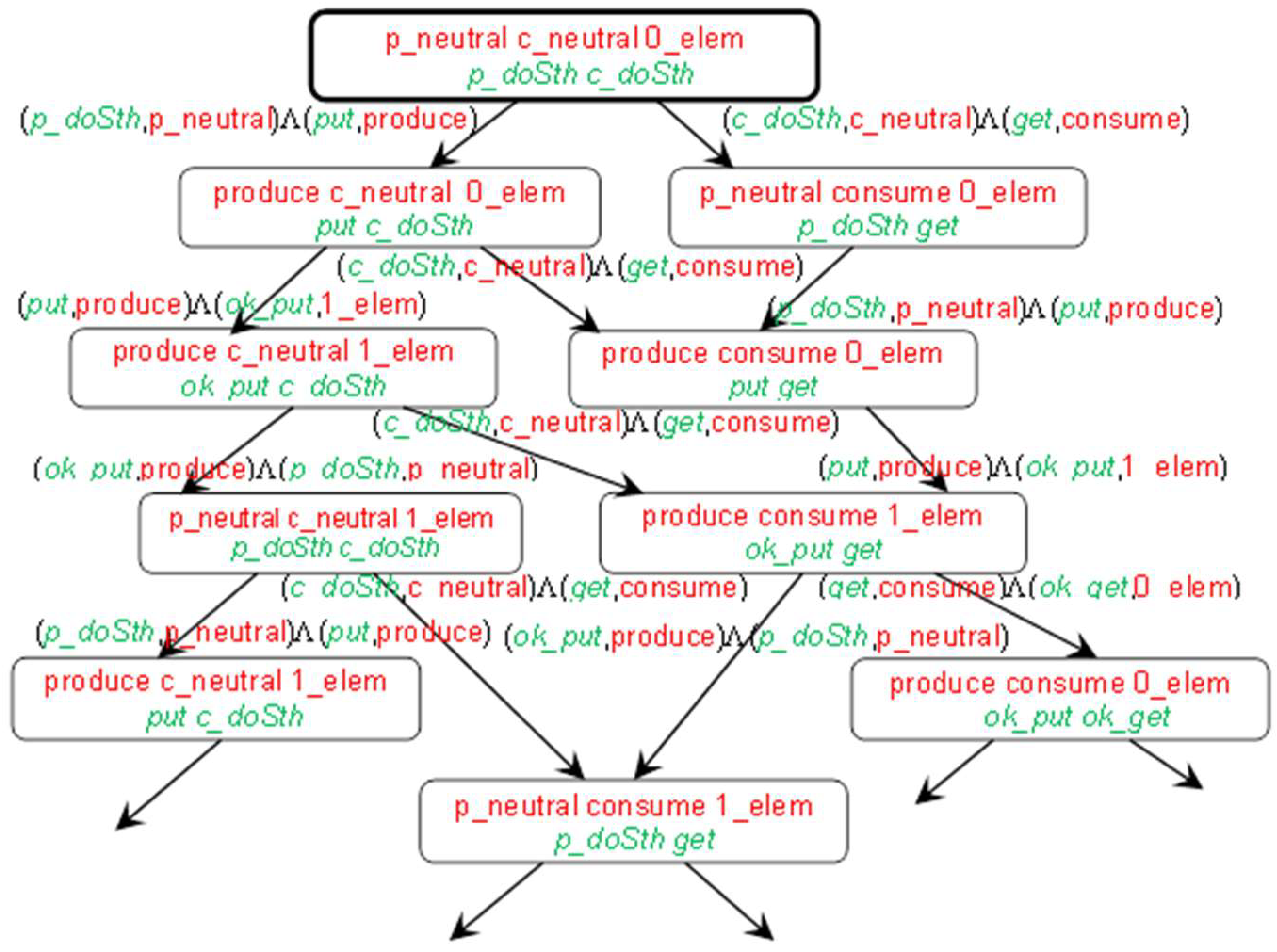
  • N is a set nodes, N = {n0,n1,…};
  • n0 is the root, n0N, n0= Tini;
  • W is the set of directed labeled transitions, WN × Λ × N, W = {(Tinp(λ),λ,Tout(λ))|λΛ}.
Because single actions are LTS labels, this means the system’s interleaving semantics [54], i.e., one action is performed at a time. Execution of the action converts the input configuration to the output configuration in such a way that the input pair (message, state) is removed and replaced by the output pair (next message, next state). Messages and states not included in the input pair remain unchanged. LTS contains all possible system runs as paths in the graph.
A fragment of LTS for the example in Figure 2 is presented in Figure 3.

3.4. IMDS Processes

The system starts working from the initial states of all servers (one state for each server) and the initial messages of all agents (one message for each agent). Because the action is performed on the server, in each action, the input message must be directed to the server appointed by the input state. The next state generated in the action appoints the same server as the input state. This ensures the server’s continuity. Similarly, the next message generated in action appoints the same agent as the input message. This ensures the continuity of the agent’s behavior.
The formal definition of IMDS for the purpose of processes extraction follows:
S = {s1,s2,}—finite set of servers,
A = {a1,a2,}—finite set of agents,
P(s) = {p1s,p2s,}, sS—finite set of states of the server s,
M(a) = {m1a,m2a,}, aA—finite set of messages of the agent a,
M(s) = {m1s,m2s,}, sS—finite set of messages directed to the server s.
For the elements of sets P(s), M(a) and M(s), we say that an element appoints a corresponding server, agent and server, respectively.
The sets in the example are (initial elements are highlighted by boldface):
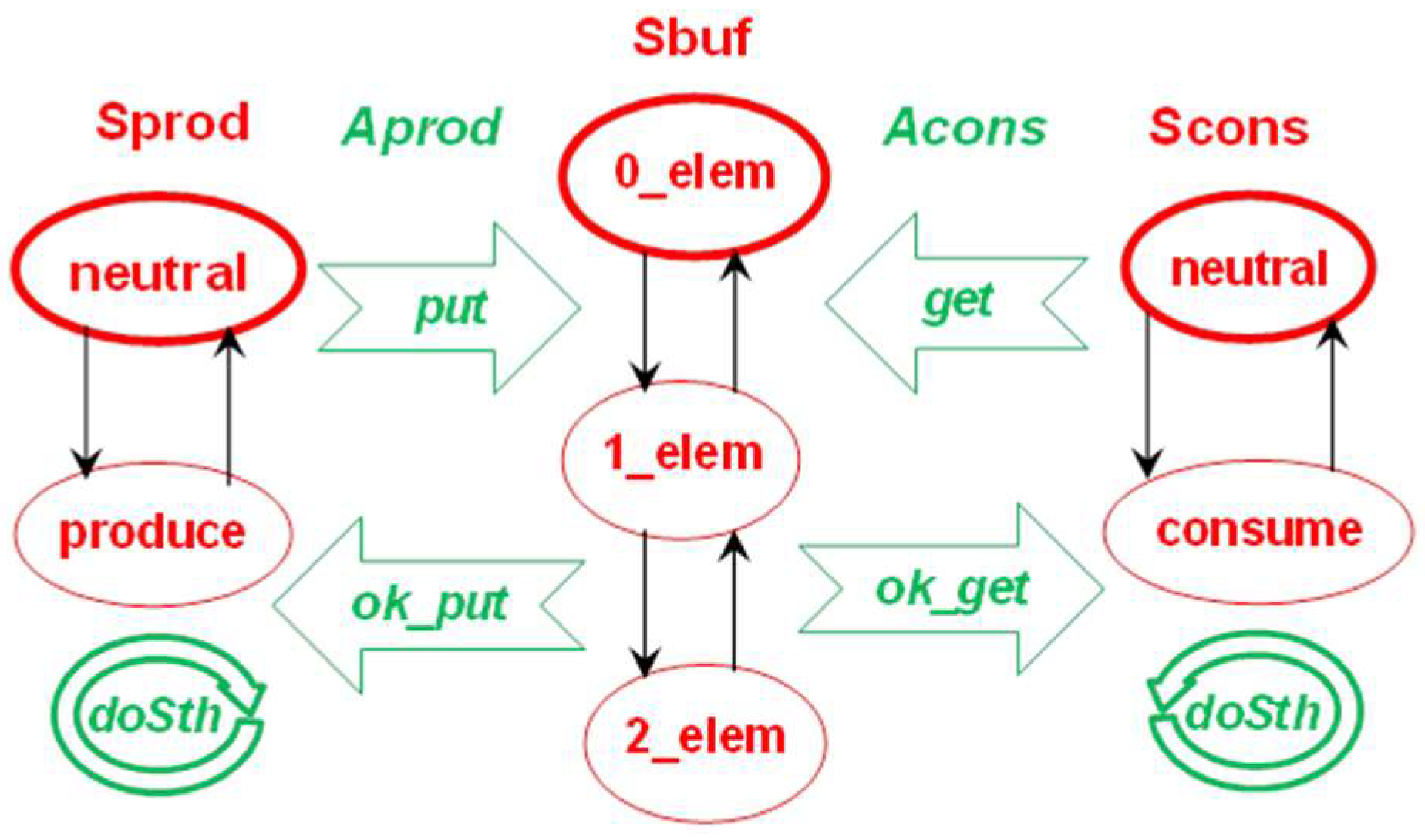
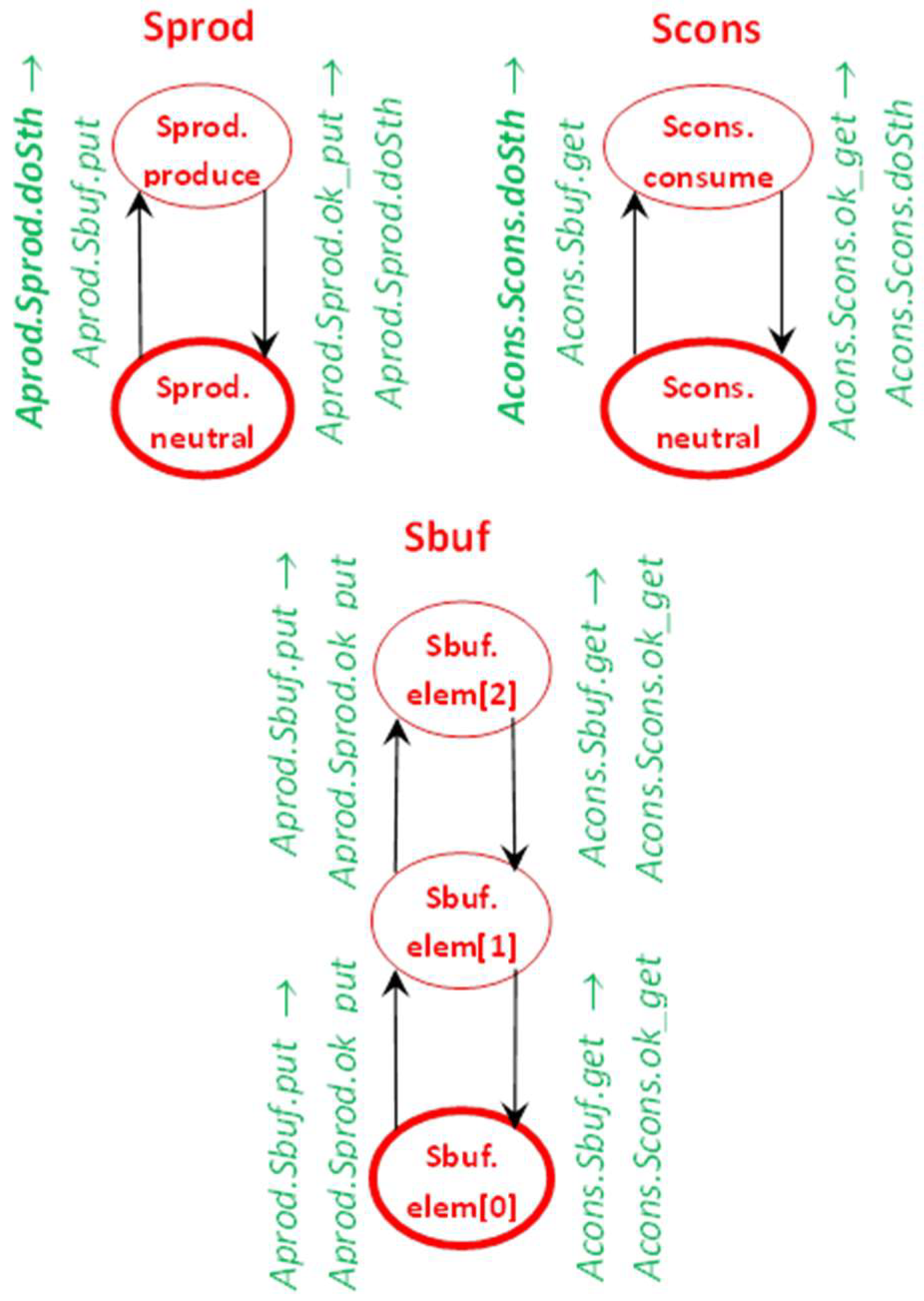
  • S = {Sprod, Scons, Sbuf},
  • A = {Aprod, Acons},
  • P(Sprod) = {p_neutral, produce}, P(Scons) = {c_neutral, consume}, P(Sbuf) = {0_elem, 1_elem, 2_elem},
  • M(Aprod) = {p_doSth, put, ok_put}, M(Acons) = {c_doSth, get, ok_get},
  • M(Sprod) = {p_doSth, ok_put}, M(Scons) = {c_doSth, ok_get}, M(Sbuf) = {put, get}.
Extracting processes requires some restrictions on P, M and Λ—each state must appoint some server, each message must appoint some agent and must be directed to some server. In addition, the action input state and input message must appoint the same server; the input and output states must appoint the same server; the input and output messages must appoint the same agent:
P = ∪sS P(s), ∀s1,s2S s1s2P(s1)∩P(s2) = ∅,
M = ∪aA M(a) = ∪sS M(s), ∀a1,a2A a1a2M(a1)∩M(a2)=∅, ∀s1,s2∈S s1s2M(s1)∩M(s2) = ∅,
λΛ λ = ((m,p),(m’,p’)), mM(a)⇒m’∈M(a), pP(s)⇒(p’∈P(s) ⋀ mM(s)),
sS card(P(s)∩Pini) = 1—initial set of states contains exactly one state for every server;
aA card(M(a)∩Mini) = 1—initial set of messages contains exactly one message for every agent.
We add a new type of agent-terminating action, in which a next message is absent:
Λ ⊂ (M × P) × (M × P) ∪ (M × P) × (P)
set of actions (Thus, Λ is not strictly a relation, because it contains both quadruples and triples. More formally, a message “agent termination” may be added to M, which is prohibited on input of any action.)
The constraints on the input pair and output singleton in an agent-terminating action, and on obtaining Tout(λ) from Tinp(λ) for an agent-terminating action, are similar to those of regular actions (8,4):
λΛ λ = ((m,p),(p’)), pP(s)⇒p’∈P(s) ⋀ mM(s)
λΛ λ = ((m,p),(p’)), Tinp(λ)⊃{m,p}, Tout(λ)=Tinp(λ)\{m,p} ∪ {p’}
The definition of Tini (5), together with rule of obtaining Tout from Tinp (4), ensure that every configuration contains exactly one state for every server and exactly one message for every non-terminated agent.
Asynchronous sequential processes in the system are defined as sequences of actions. Note that the two output elements of any action (or one output element for the agent-terminating action) can be input elements of other actions. Thus, the sequence of actions is threaded by intermediate elements. If we choose states as a process carrier, we will get the server process running along with the changing server states. The states between actions define the succession relation between actions. From this perspective, intermediate messages are passed between actions of different server processes, i.e., they serve as a means of communication. Note that the server processes do not terminate (in the sense of the terminating action); the output state is present in each action.
On the other hand, we can choose messages for threading actions. From this perspective, the agent’s messages form the agent’s process. The messages between actions define the succession relation between actions. The process runs along messages, and visited server states are a means of communication. Because there can be actions without an output message, agent processes can be terminated.
For the server process of a server s: the first process action has an initial server state on the input, all threading states appoint the server s:
B(s) = <λ0,λ1,>|∀i=0,…λiΛ;
λ0 = ((m,p),(m0,p0)) ⋁ λ0 = ((m,p),(p0)), pPini ∩∈P(s);∀i>0 λi-1 = ((m,p),(m1,p1)) ⋁ λi−1 = ((m,p),(p1)), λi = ((m2,p2),(m3,p3)) ⋁ λi = ((m2,p2),(p3)), p1, p2P(s), p1 = p2
For the agent process of an agent a: the first process action has an initial agent message on the input, all threading messages appoint the agent a:
C(a) = <λ0,λ1,> | ∀i =0,… λiΛ;
λ0 = ((m,p),(m0,p0)) ⋁ λ0 = ((m,p),(p0)), mMiniM(a);∀i>0 λi-1 = ((m,p),(m1,p1)), λi = ((m2,p2),(m3,p3)) ⋁ λi = ((m2,p2),(p3)), m1,m2M(a), m1= m2
We call processes as asynchronous sequential, because:
  • action sequences come from their definition;
  • asynchrony comes from such a feature that always the state of the server is waiting for a message, or a message pending at the server is waiting for the matching state of this server (and, at the same time, the state is waiting for a matching message).
Note that in the succession graph:
  • A process can have more than one starting node if more than one action can appear first in the process.
  • The process may be a branched graph if there is non-determinism in the action set: it may be possible to perform multiple actions for a given state or for a given message.
  • Some paths in the graph may be finite if there is an action that terminates the agent’s operation, or if no action is defined for a given state / message (this is not considered a process termination).
For the “Bounded buffer” example in Figure 2, Figure 4 presents server processes and Figure 5 shows agent processes.
The Labeled Transition System (LTS [12]) defines the semantics of the modeled system. If the configuration contains a state and message that match, the action is prepared and can be fired. Interleaving semantics allows execution of only one of the prepared actions at a time.
Multiple actions can be simultaneously prepared on one server, all of them defined for the same, current state of the server. Due to interlacing, all these actions are in conflict. Actions prepared on separate servers are completely independent, i.e., they do not affect each other (except that they can send messages that increase the number of waiting messages on the target servers, and the number of prepared actions can increase as a result of the action).

3.5. Views of a Distributed System

The sets of actions of individual server processes are disjoint. The same applies to actions of agent process. Yet, there can be “orphaned” actions that do not belong to any server/agent. This can occur when the action has a state/message on the input that is neither initial nor present on the output of any action belonging to any process. This situation means the existence of an unreachable or “dead” code. To avoid orphaned actions, it is possible to define processes differently by grouping actions of individual servers / agents into sets instead of into sequences:
B(s) = {λΛ | λ = ((p,m),(p’,m’)) ⋁ λ = ((p,m),(p’)), pP(s)}—server process of the server s
C(a) = {λΛ | λ = ((p,m),(p’,m’)) ⋁ λ = ((p,m),(p’)), mM(a)}—agent process of the agent a
In the “Bounded buffer” example from Figure 2, the processes defined as sets of actions are:
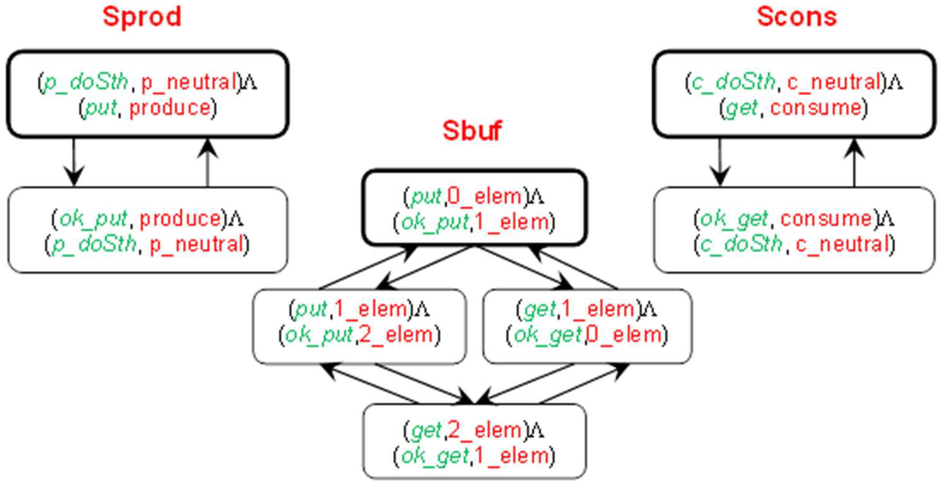
  • B(Sprod) = {(p_doSth, p_neutral)Λ(p_doSth, p_neutral), (p_doSth, p_neutral)Λ(put, produce), (ok_put, produce)Λ(p_doSth, p_neutral)},
  • B(Scons) = {(c_doSth, c_neutral)Λ(p_doSth, p_neutral), (c_doSth, c_neutral)Λ(get, consume), (ok_get, consume)Λ(c_doSth, c_neutral)},
  • B(Sbuf) = {(put, 0_elem)Λ(ok_put, 1_elem), (put, 1_elem)Λ(ok_put, 2_elem), (get, 1_elem)Λ(ok_get, 0_elem), (get, 2_elem)Λ(ok_get, 1_elem)},
  • C(Aprod) = {(p_doSth, p_neutral)Λ(p_doSth, p_neutral), (p_doSth, p_neutral)Λ(put, produce), (put, 0_elem)Λ(ok_put, 1_elem), (put, 1_elem)Λ(ok_put, 2_elem), (ok_put, produce)Λ(p_doSth, p_neutral)},
  • C(Acons) = {(c_doSth, c_neutral)Λ(c_doSth, c_neutral), (c_doSth, c_neutral)Λ(get, consume), (get, 1_elem)Λ(ok_get, 0_elem), (get, 2_elem)Λ(ok_get, 1_elem), (ok_get, consume)Λ(c_doSth, c_neutral)}.
After completing all actions for processes, we have a system decomposed into processes. Two decompositions into asynchronous sequential processes give two system views:
B = {B(s)|sS}—the server view,
C = {C(a)|aA}—the agent view.
In the example:
B = {B(Sprod), B(Scons), B(Sbuf)},
C = {C(Aprod), C(Acons)}.
Many system properties can be verified using the model checking technique. This article focuses on deadlocks and termination [55]. Different features can be observed in different views: communication deadlocks in the server view, and deadlocks over resources and distributed termination in the agent view, as shown in Section 3.6.

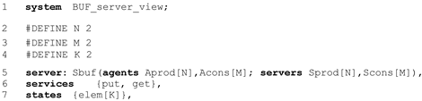
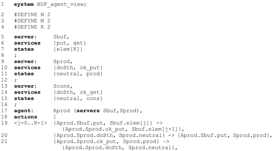
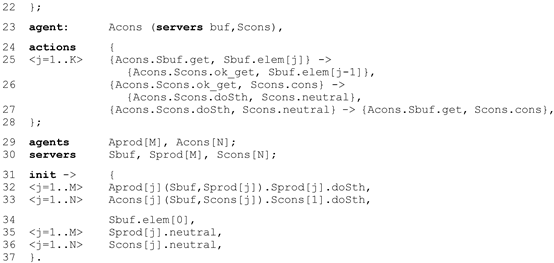
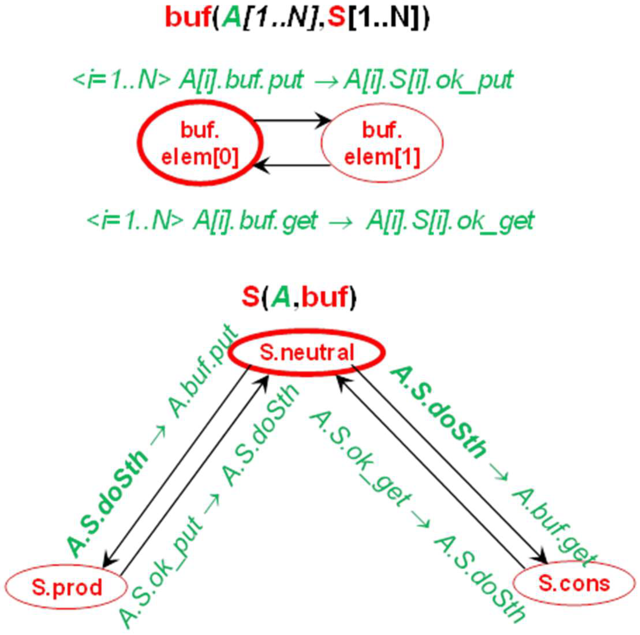
3.6. IMDS as a Programming Language

In the basic IMDS definition, states and messages were defined as simple, indivisible entities (Section 3.2). In some situations, we use the attributes of states and messages, formed by appointed servers and/or agents (sets P(s), M(a), M(s)). In the Dedan program designed for verification of distributed systems, IMDS is used as the specification language. To be able to define server types and agent types, and declare variables of these types, it is better to specify a server state as a pair (server, value). A message can also be defined as a pair (agent, target server). However, the agent can call various server operations, for example P and V operations on the semaphore. These operations will be called “services”. Messages are therefore defined as triples (agent, server, service). In such a formulation, a message is an invocation of a server’s service by an agent. Below is a formal definition of actions in terms of states as pairs and messages as triples.
The basic sets are servers, agents, values and services:
S = {s1,s2,}—finite set of servers,
A = {a1,a2,}—finite set of agents,
V = {v1,v2,}—finite set of values,
R = {r1,r2,}—finite set of services.
An action is an execution of a service on a server in a context of an agent.
PS × V—set of states
MA × S × R – set of messages
In the Dedan program, we use the notation s.v and a.s.r for pairs (s,v) and triples (a,s,r), and the notation {a.s.r, s.v}→{a,s’.r’, s.v’} for an action ((a,s,r),(s,v))Λ((a,s’,r’),(s,v’)).
A simple example of bounded buffer with capacity K = 2 is presented in Figure 6. It is a development of the system shown in Figure 2. It is the server view of a system consisting of a producer, a consumer, and a buffer. Note that the states and messages are specified as pairs and triples. Messages are input and output symbols on transitions leading from one server state to another. The rules for this figure are:
  • every server is depicted as separate automaton-like graph of Mealy type [56],
  • nodes of an automaton are the server’s states,
  • initial node (initial state) is surrounded by bold ellipse,
  • initial messages of the agents are in bold font,
  • transitions are actions,
  • transitions are labeled by input messageoutput message.
In the example, three servers cooperate: the buffer containing 0, 1, or 2 elements, the producer spontaneously creating new elements and then sending them to the buffer, and the consumer retrieving the elements from the buffer and destroying them. The message invoking a buffer’s action is accepted if the operation is possible, for example it is forbidden to place the element in a full buffer. Consider the upper-left action on the Sbuf server: the buffer is empty (a value elem[0] denotes 0 elements in the buffer) and the Aprod agent message is pending at Sbuf. The message invokes the Sbuf server put service. Execution of the action inserts the element to the buffer: it changes its state from the value elem[0] to the value elem[1]. After completing the put service, the Sbuf server issues the same agent Aprod message to the server Sprod, invoking its service ok_put. Note that in the server Sbuf state elem[2], the a message invoking a service put cannot be accepted. If this message is received, it remains pending (the sets of pending messages are not shown in the figure, they are present in the formal definition of distributed automata DA3, equivalent to IMDS [57]).
The full source code of the buffer example in the server view is as follows: Computers 07 00065 i001a Computers 07 00065 i001b
The notation is intuitive: the (optional) header contains the system name (line 1). The server types are defined first (l.5,14,21), then servers (l.26), agents (l.27) and initialization part (l.28). A server type consists of formal parameters defining servers and agents used (l.12), server’s services (l.13), states (l.14), and the actions of the server (l.9–10). The states of the buffer (a number of elements) are implemented as a vector (l.7). In the initialization part, the actual parameters (agents and servers) are passed to every server (l.29–31) and the initial state of every server is defined after the dot. For every agent, the initial message is defined (l.32,33).
The system converted to the agent view is given below. It is a manual conversion, to preserve the constants M, N, and K. The automatic translation is almost identical, but the constants M, N, and K appear as specific numbers (in the Dedan conversion the symbolic constants disappear). Computers 07 00065 i002a Computers 07 00065 i002b
The (optional) header contains the system name (line 1). The server types are defined first (l.5,9,13). They contain services and states definitions only, as the actions are attributed to the agents. Agent types are defined separately (l.17,23), then agents (l.29), servers (l.30), and the initialization part (l.32). An agent type consists of formal parameters defining servers used (l.17,23) and the actions of the agent (l.19–21,25–27). In the initialization part, the actual parameters (servers) are passed to every agent (l.32–33), and the initial message of every agent is defined. For every server, the initial state is defined (l.34–36).
The presented input of the Dedan program follows IMDS formulation and it is uncomfortable for programmers. Therefore, the Rybu preprocessor for imperative-like programming was developed by the students of ICS, WUT under the supervision of the author. The students of second-year studies use the Rybu language in verification of their synchronization solutions. The Rybu language exceeds the scope of this paper, but is described in [58]. More than 200 students verified their exercises, and in their opinion the Dedan/Rybu program, is not difficult to use. Some of the models exceed six thousand actions.
Most student exercises are in RPC paradigm. However, we modeled systems of several schemes:
  • communication protocols,
  • train scheduling,
  • distributed production cell,
  • automatic vehicles guidance,
  • patrol robots swarm,
  • distributed systems for access control,
  • business processes.
Models can be expressed in different programming languages, but the designer must keep in mind that a typical programming language is based on globally available variables, regardless of whether it is sequential or parallel. The distributed system’s specification should not contain global variables or centrally-started processes/threads. Individual servers or agents can be defined in traditional languages, but somehow they should be combined into a distributed system.

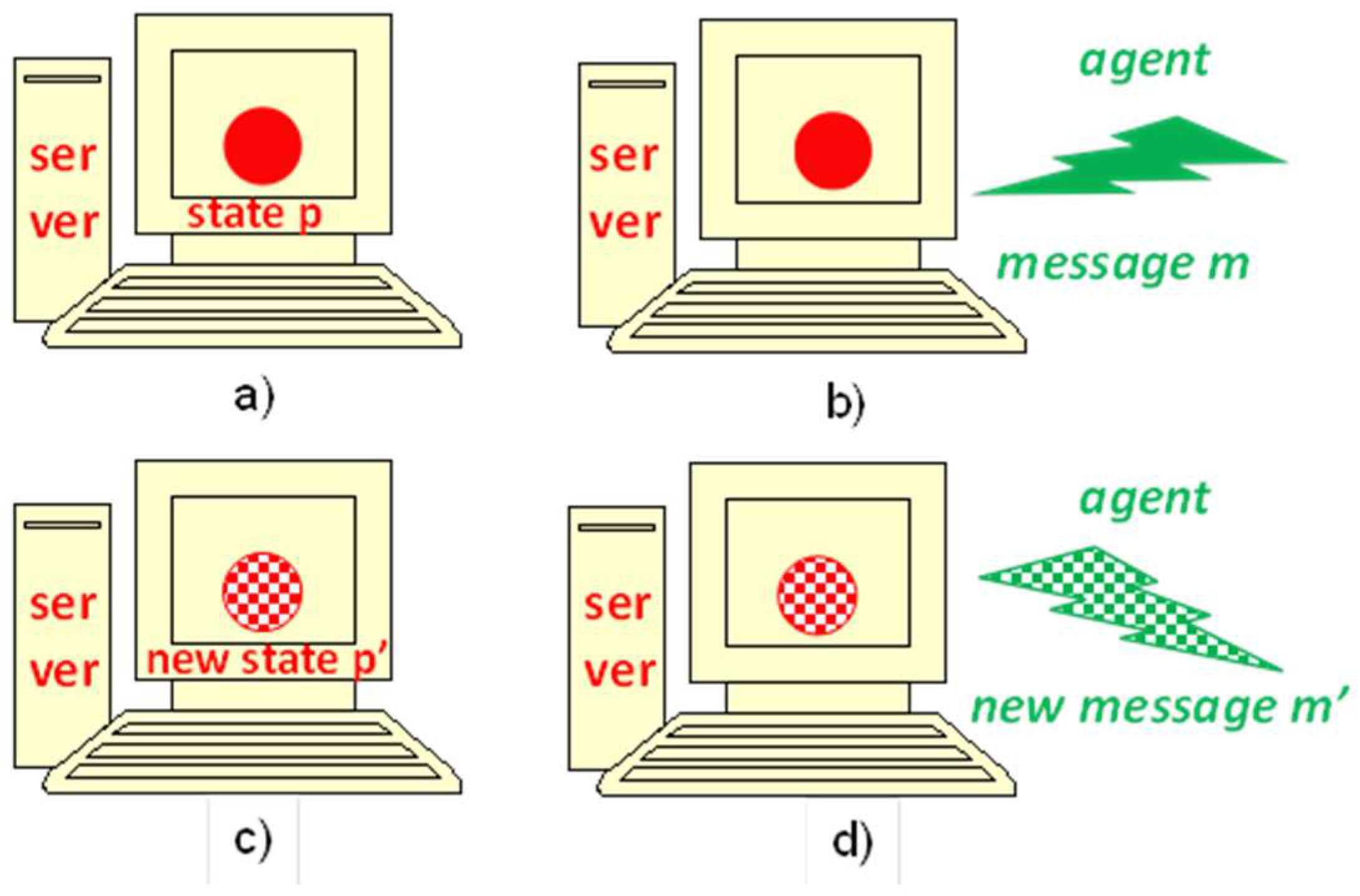
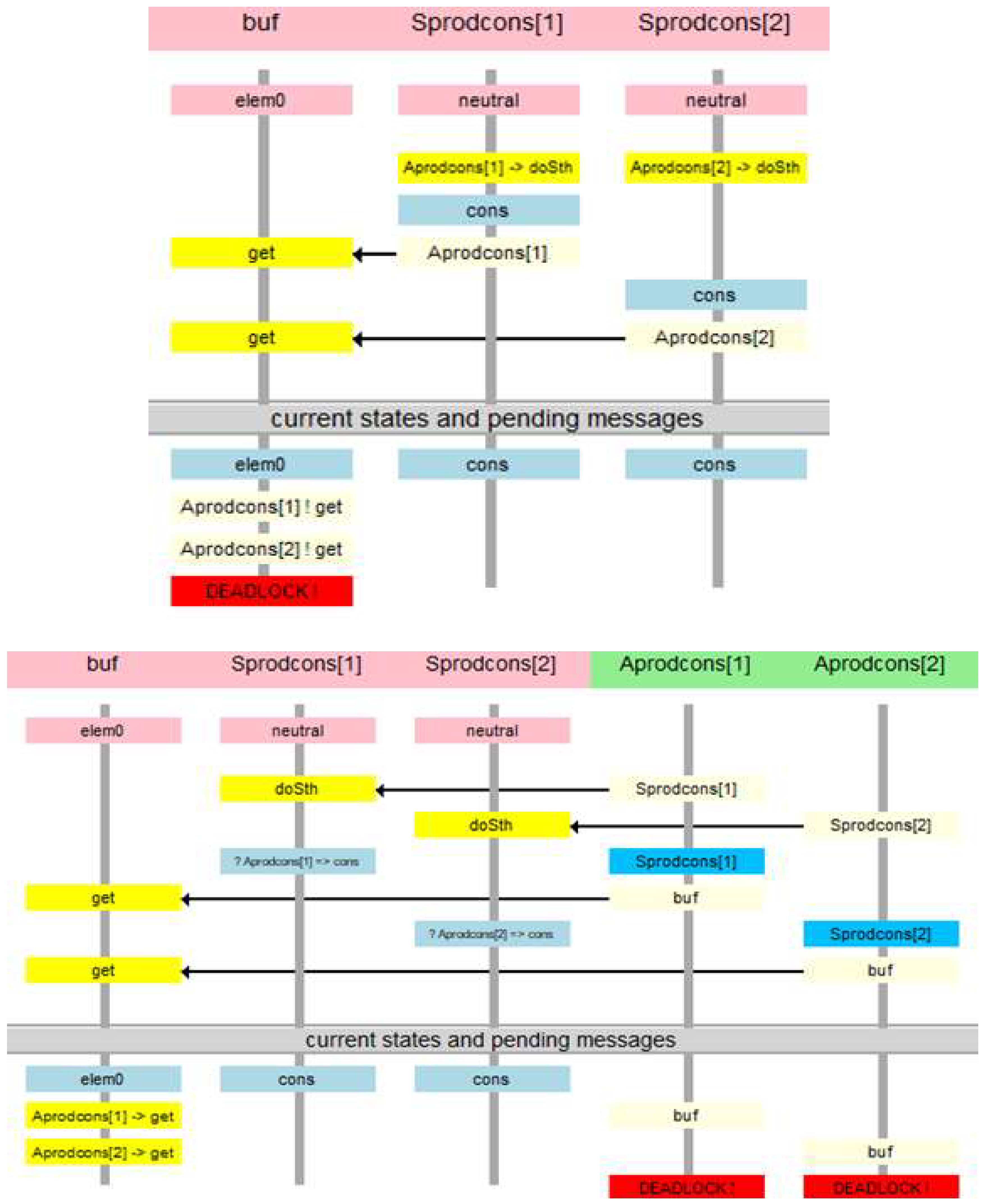
3.7. Deadlock and Termination

The verification methodology, composed of the IMDS specification and temporal verification [11], allows the designer to specify a distributed system in order to observe the server and agent views of the system and to easily find various types of deadlocks (total/partial deadlock, communication/resource deadlock) and distributed terminations of processes (also total/partial).
An example of deadlock in the IMDS server view is when two servers are waiting for messages from each other. It is a communication deadlock, because the manner of cooperation between server processes is message passing. The definition of a communication deadlock in IMDS is a situation where there are pending messages on the server (at least one), but they can never be ever served. A deadlock can affect all servers (total deadlock) or a subset of servers (partial deadlock); even a single server may be involved.
In the agent view, a deadlock is a situation in which an agent has a message pending on some server, but the agent cannot make any progress. The message cannot be served, but messages of other agents possibly can. Again, the deadlock may concern all agents (total deadlock) or a subset of system agents (partial deadlock). Note that according to this definition, a single process may be deadlocked. Such a situation is sometimes called starvation [59] or stall [60].
A (partial) termination in IMDS is simply the disappearance of the agent: the agent-terminating action binds an input pair (message, state) with an output singleton (next state) only. The action generates a new server state but does not generate the next message.
Model checking is a method often used in the static deadlock detection or termination verification in distributed systems [20,48]. The model checker automatically detects situations such as deadlock or missing of termination, using system specification and temporal formulas. System-independent temporal formulas for deadlock and termination verification are defined by the author over IMDS elements (configurations and actions) [11]. The generality of formulas means that they do not depend on specific features of processes in a given system. As arguments, only the characteristics of server processes and agent processes specified by IMDS are used. The two views of a specification make it possible to find communication deadlocks and resource deadlocks. In other formalisms, there are formulas that are independent of the verified system to find a total deadlock, but they do not distinguish the deadlock from termination, and usually only concern a total deadlock. Some verifiers perform automatic detection of a partial deadlock, but only in cases where the scheme of the verified system is strictly limited. A similar limitation applies to checking partial termination. If the structure of the system is not limited, the designer must have some knowledge of temporal logic or equivalent formalisms in order to carry out the verification. Also, none of known verifiers distinguishes communication deadlocks from resource deadlocks. In addition, none of the known verifiers distinguish between deadlocks and resource deadlocks. A detailed analysis of the deadlock detection and termination checking techniques is given in [11].
If the process falls into a deadlock or if it does not terminate, the model checker creates a counterexample for the program defect. The counterexample supports the designer in finding and correcting the errors in the specification. A counterexample in IMDS is a sequence of configurations and actions leading from the start of the system to the erroneous configuration.
The system-independent formulas—used for deadlock detection and termination checking—provide automated verification. Therefore, the formulation and verification of properties are performed automatically inside a modeling program Dedan [61], and the user only sees the final results. The designer must absorb the IMDS formalism and the language of specification.
In IMDS, deadlock is defined as a situation in which a process that is not terminated and cannot be continued (at the moment and in the future). The formal definition of server processes and agent processes is different, because they have different characteristics.
The following situations may occur in the server process:
  • on the server there is a matching pair (message, state)—the action is prepared; the process runs;
  • there are pending messages or not, but there is no matching pair on the server; a matching pair can happen in the future, so the server process waits;
  • there are no pending messages, and in the future, no message will arrive at the server; the process is idle;
  • there are pending messages in the server, but there is no matching pair, and such a pair cannot occur on the server in the future; the process is deadlocked.
The former three cases are not dangerous because they are typical of the process flow. For example, servers are waiting for a service invocation that will never happen. The server process never terminates, but it can remain idle. The latter case denotes a deadlock, i.e., some messages are waiting for acceptance by the execution of specific actions, but the current state of the server does not match any of the messages, nor will it match them in the future. Because the means of cooperation of server processes is message passing, it is a communication deadlock.
Cases for the agent process are:
  • the agent message is pending at the server and it matches the current state of this server—the action is prepared; the agent runs;
  • the agent message is pending at a server but it does not match the current state of this server; a matching pair containing this message may occur in the future; the agent is waiting;
  • the agent message is pending at the server and it will never match any state of this server—neither now nor in the future; the process is deadlocked;
  • the agent-terminating action was executed and the agent’s message is not present (and will not occur in the future)—the process is terminated.
The former two cases are normal operation of the agent process. The third case means deadlock—the agent message is pending at the server but it will never match any server state. It is a resource deadlock, because agent processes communicate by changing servers’ states. The last case denotes agent termination just from the definition of the agent-terminating action.

4. Model Checking of the IMDS Specifications in the Dedan Environment

The Dedan environment was developed by the author for the practical application of the proposed verification methodology [61]. The Dedan program contains an internal model checker TempoRG using the CBS algorithm, developed by the author [4,62]. The verification algorithm was adapted to be used in the Dedan program: it was simplified to a limited set of formulas (for deadlock and termination checking). Reverse reachability was used to identify different cases of the reachability space shape. This verifier uses an explicit reachability space, which allows for dealing with rather small specifications, such as student exercises. For larger specifications, external model checkers are used: Spin [19], NuSMV [63] and Uppaal [24].
The system’s LTS is naturally interpreted as the Kripke Structure [20]: the finite set of nodes—configurations, the initial node—the initial configuration, the total transition relation—actions. Formally, for configurations in which no pairs match (they mean total deadlock or total termination), self-loops should be added. The labeling of nodes consists of assigning a set of atomic Boolean formulas that are true in a given node. This labeling is obvious for IMDS configurations (see Table 1). Therefore, the model checking technique can be applied to LTS analysis, especially to find deadlocks and check termination of processes.
We define a server communication deadlock as a situation in which the current state of the server does not match any message pending at the server, and the server will not receive any message matching this server state in the future. In cases of detecting a communication deadlock, we label the LTS nodes using the Boolean formulas:
  • Dstrue in all configurations where at least one message is pending at the server s,
  • Estrue in all configurations where at least one action is prepared in the server s.
The formulas that identify a communication deadlock and server idleness are given in Table 1.
We define resource deadlocks as situations in which the agent process message is pending at a server, but it will never match any state of this server. The termination of the agent is simply the execution of its termination action. We need the following labelling of the LTS:
  • Datrue in all configurations in which agent a message is pending,
  • Eatrue in all configurations in which the action with agent a message on input is prepared,
  • Fatrue in all configurations where the terminating action (with the agent a message on input) is prepared.
The formulas for the agent falling into a resource deadlock and for agent termination are given in Table 1.
Note that finding a deadlock concerns individual processes, not the entire system. This feature distinguishes the presented technique from other static deadlock detection approaches through model checking.
The formulas for deadlock detection and termination checking given in Table 1 do not depend on the structure of the verified system. Therefore, everything a user must do is a system specification as a set of actions over sets of messages and states. An example specification is given in Section 3.6. Then, the verification is run automatically in Dedan in “push the button” style, giving the counterexamples if a deadlock is found.
The complexity of the verification is typical: it is P-Complete [64], which means that the evaluation time of the time formula is |LTS| × |φ|, where |LTS| denotes the number of nodes in the Labeled Transition System, and |φ| is the length of a formula φ. Every formula has one or two temporal operators; therefore, this factor is constant. In the case of large systems, we use the Uppaal verifier [24], which is equipped with a symbolic representation of the reachable space.

5. Example Verification

The example of verification in Dedan concerns a bounded buffer system, similar to that in Figure 2, but with the capacity K = 1 and with modified users. The users are modified to play roles of both producers and consumers. Such a system is depicted graphically in Figure 7. The source code can be found in the set of examples [65]. The system falls into a deadlock if all users decide to get from an empty buffer, or when everyone chooses to put into a full buffer.
Figure 8 presents the communication deadlocks identified by the Dedan verification tool. It shows the “get” deadlock, because the counterexample for this deadlock is shorter (“put” deadlock requires 3 put messages, while “get” deadlock requires 2 get messages).
The question arises: what is the difference between these two types of deadlock? If a communication deadlock occurs, servers cannot perform any action while there are messages pending on the servers. These messages represent agents, which is why agents are also in deadlock over resources. However, the interpretation of the deadlock found is different for the two views, since the counterexamples are constructed in different ways. The counterexample of a communication deadlock is a sequence diagram in which states are woven on the timelines of servers, and messages flow between the server timelines. The counterexample of resource deadlock is that the agent’s timeline displays messages directed to individual servers.
A deadlock over resources that does not occur as a communication deadlock can happen if the system does not have enough resources. In this deadlock, no server is stuck because it accepts messages from other agents and responds to these messages. However, there are some agents whose messages will never match any state of these servers.
The bounded buffer is just an example. Other simple examples can be found in [65]. There are some benchmarks in the literature, mainly synchronic systems or systems having a global state available, such as the solitaire game, 4-queen problem, 8-puzzle, dining philosophers, etc. The latter, converted into a distributed version, is included in [65].
The Karlsruhe Production Cell is a serious benchmark [66]. Most of the verification examples are synchronous, but several asynchronous models can be found in the literature. In our solution, the asynchronous model is verified [53], in which distributed devices are modeled as servers, and metal plates moving through the cell are modeled as agents. Our verification finds an expected deadlock, but none of the other solutions can express the deadlock from the perspective of cooperating controllers (server view) and from the perspective of metal plates traveling through the cell (agent view). However, the main benefit comes from automatic verification using Dedan. Most examples of Karlsruhe Production Cell verification use formulas that are individually designed for the verification.
Similarly, in automatic vehicle guidance systems [52], the communication deadlock can be observed in road segment controllers cooperation, which is modeled as a server. The resource deadlock is visible from the guided vehicle’s perspective, which is modeled as an agent.

6. Conclusions

The presented IMDS formalism, in combination with model checking using general formulas, satisfies the desired features in modeling and verification of distributed systems:
  • Communication duality: any system can be decomposed into server processes communicating through messages, or into agent processes communicating via servers’ states.
  • Locality: each action on the server is performed based on the current state of this server and the set of messages pending at this server. No external event (except messages received by the server) affects the behavior of the server.
  • Autonomy: each server decides by itself which of the prepared actions will be executed and when. In other words, the servers decide autonomously whether and when communication will be accepted and what actions will result.
  • Asynchrony: the server accepts the message when it is ready for it (its state matches the message); otherwise, the message is waiting; there is no synchrony in the model, i.e., no simultaneous activities of servers or agents.
  • Asynchronous channels: the communication between the servers is unidirectional; the possible communication in the opposite direction has its own channel.
  • Automated verification: the temporal formulas are used to locate communication deadlocks in individual server processes, resource deadlocks in agent processes, servers’ idleness, and agents termination.
The IMDS formalism and general temporal formulas, not related to the structure of the verified system, have made it possible to build an automatic Dedan verifier. The program can be used without knowledge of temporal logics and model checking. Temporal logic formulas are “wired” in Dedan itself. The main features of Dedan, which finds communication deadlocks, resource deadlocks, and distributed termination, in both total and partial form, and produces counterexamples in sequence diagram form, are to simplify the development of distributed systems.
IMDS was the basis of several new ideas and mechanisms for the specification and verification of distributed systems. The Rybu imperative language was developed for the ease of specification. Several non-trivial systems and over 200 student exercises were successfully verified. The structure of the verified system is not restricted, provided that it can be modeled as a set of actions over states and messages. The only limitation is due to the fact that the model must be bounded to be statically verified; features such as broadcasting messages, consumable resources, or dynamically-created processes are difficult to specify. This limitation can be overcome with a static pool of agents waiting to be activated. They can be enabled in the splitting of the process, creating a consumable resource, launching a process in a cloud application, or issuing a broadcast message. However, the dynamic creation of processes would be more natural.
In the Dedan program, several new verification facilities were developed, including a converter to Petri nets for structural analysis and siphon-based deadlock detection. This procedure allows for finding multiple deadlocks in single verification run [57,67,68,69,70]. Asynchronous and Autonomous Distributed Automata (DA3 [57]), in two forms of server automata and agent automata, are designed for simulation of distributed systems over its elements, and to simulate the counterexamples.
The behavior of the distributed system may change if specific time constraints are imposed on its elements. For the specification and verification with real time constraints, a timed version of IMDS is developed [71,72].
The next steps are:
  • Reachability space reduction and symbolic representation.
  • Checking for assertions expressed in terms of states and messages.
  • Code mobility—equipping the agents with their own sets of actions, carried in their “backpacks”, parameterizing the behavior of individual agents. This will allow the modeling of agents with mobile code and avoiding many server types in the specification, differing slightly [73].
  • Dynamic creation of processes—a state of a new server and/or a message of a new agent created in action [10], some problems with the calculation of the reachability space of such a system must first be solved. In order to be statically verified, the LTS of the Petri net corresponding to the IMDS system should be limited, e.g., restricting markings to a certain limit [74].
  • Probabilistic automata to identify the probability deadlocks, if the alternative actions in system processes are equipped with probabilities [75].
  • Non-exhaustive search for model checking large systems. The own algorithm for partial deadlock detection is elaborated, and the algorithm for timed systems is under development.

Funding

This research received no external funding.

Acknowledgments

I would like to thank Wlodek Zuberek for his help in formulation of the current version of IMDS definition.

Conflicts of Interest

The author declares no conflict of interest.

References

  1. Schaefer, I.; Hahnle, R. Formal Methods in Software Product Line Engineering. Computer 2011, 44, 82–85. [Google Scholar] [CrossRef]
  2. Mieścicki, J. The use of model checking and the COSMA environment in the design of reactive systems. Ann. UMCS Inform. 2006, 4, 244–253. [Google Scholar] [CrossRef]
  3. Mieścicki, J.; Baszun, M.; Daszczuk, W.B.; Czejdo, B. Verification of Concurrent Engineering Software Using CSM Models. In Proceedings of the 2nd World Conference on Integrated Design and Process Technology, Austin, TX, USA, 1–4 December 1996; pp. 322–330. [Google Scholar]
  4. Daszczuk, W.B. Evaluation of temporal formulas based on “Checking By Spheres”. In Proceedings of the Euromicro Symposium on Digital Systems Design, Warsaw, Poland, 4–6 September 2001; pp. 158–164. [Google Scholar] [CrossRef]
  5. Daszczuk, W.B.; Grabski, W.; Mieścicki, J.; Wytrębowicz, J. System modeling in the COSMA environment. In Proceedings of the Euromicro Symposium on Digital Systems Design, Warsaw, Poland, 4–6 September 2001; pp. 152–157. [Google Scholar] [CrossRef] [Green Version]
  6. Daszczuk, W.B.; Mieścicki, J.; Nowacki, M.; Wytrębowicz, J. System Level Specification and Verification Using Concurrent State Machines and COSMA Environment. In Proceedings of the 8th International Conference on Mixed Design of Integrated Circuits and Systems (MIXDES’01), Zakopane, Poland, 21–23 June 2001; pp. 525–532. [Google Scholar]
  7. Mieścicki, J.; Czejdo, B.; Daszczuk, W.B. Model Checking in the COSMA Environment as a Support for the Design of Pipelined Processing. In Proceedings of the European Congress on Computational Methods in Applied Sciences and Engineering (ECCOMAS 2004), Jyväskylä, Finland, 24–28 July 2004; pp. 24–28. [Google Scholar]
  8. Mieścicki, J.; Daszczuk, W.B. Behavioral and real-time verification of a pipeline in the COSMA environment. Ann. UMCS Inform. 2006, 4, 254–265. [Google Scholar] [CrossRef]
  9. Lee, G.M.; Crespi, N.; Choi, J.K.; Boussard, M. Internet of Things. In Evolution of Telecommunication Services; LNCS 7768; Springer: Berlin/Heidelberg, Germany, 2013; pp. 257–282. [Google Scholar]
  10. Chrobot, S.; Daszczuk, W.B. Communication Dualism in Distributed Systems with Petri Net Interpretation. Theor. Appl. Inform. 2006, 18, 261–278. [Google Scholar]
  11. Daszczuk, W.B. Communication and Resource Deadlock Analysis using IMDS Formalism and Model Checking. Comput. J. 2017, 60, 729–750. [Google Scholar] [CrossRef]
  12. Reniers, M.A.; Willemse, T.A.C. Folk Theorems on the Correspondence between State-Based and Event-Based Systems. In Proceedings of the 37th Conference on Current Trends in Theory and Practice of Computer Science, Nový Smokovec, Slovakia, 22–28 January 2011; pp. 494–505. [Google Scholar] [CrossRef]
  13. Jia, W.; Zhou, W. Distributed Network Systems: From Concepts to Implementations; Springer: New York, NY, USA, 2005. [Google Scholar]
  14. Kessler, C.; Keller, J. Models for Parallel Computing: Review and Perspectives. In PARS-Mitteilungen; Gesellschaft für Informatik: Bonn, Germany, 2007; pp. 13–29. [Google Scholar]
  15. Milner, R. Calculi for synchrony and asynchrony. Theor. Comput. Sci. 1983, 25, 267–310. [Google Scholar] [CrossRef]
  16. Savoiu, N.; Shukla, S.K.; Gupta, R.K. Automated concurrency re-assignment in high level system models for efficient system-level simulation. In Proceedings of the 2002 Design, Automation and Test in Europe Conference and Exhibition, Paris, France, 4–8 March 2002; pp. 875–881. [Google Scholar] [CrossRef] [Green Version]
  17. van Glabbeek, R.; Goltz, U.; Schicke, J.-W. On Synchronous and Asynchronous Interaction in Distributed Systems. In Proceedings of the 33rd International Symposium (MFCS 2008), Toruń, Poland, 25–29 August 2008; pp. 16–35. [Google Scholar]
  18. Rosa, N.S.; Cunha, P.R.F. A Software Architecture-Based Approach for Formalising Middleware Behaviour. Electron. Notes Theor. Comput. Sci. 2004, 108, 39–51. [Google Scholar] [CrossRef]
  19. Holzmann, G.J. Tutorial: Proving properties of concurrent systems with SPIN. In Proceedings of the 6th International Conference on Concurrency Theory (CONCUR’95), Philadelphia, PA, USA, 21–24 August 1995; pp. 453–455. [Google Scholar] [CrossRef]
  20. Clarke, E.M.; Grumberg, O.; Peled, D. Model Checking; MIT Press: Cambridge, MA, USA, 1999; ISBN 0-262-03270-8. [Google Scholar]
  21. Zielonka, W. Notes on finite asynchronous automata. RAIRO Theor. Inform. Appl. Inform. Théor. Appl. 1987, 21, 99–135. [Google Scholar] [CrossRef]
  22. Alur, R.; Dill, D.L. A theory of timed automata. Theor. Comput. Sci. 1994, 126, 183–235. [Google Scholar] [CrossRef]
  23. Hoare, C.A.R. Communicating sequential processes. Commun. ACM 1978, 21, 666–677. [Google Scholar] [CrossRef]
  24. Behrmann, G.; David, A.; Larsen, K.G.; Pettersson, P.; Yi, W. Developing UPPAAL over 15 years. Softw. Pract. Exp. 2011, 41, 133–142. [Google Scholar] [CrossRef]
  25. Milner, R. A Calculus of Communicating Systems; Springer: Berlin/Heidelberg, Germany, 1984; ISBN 0387102353. [Google Scholar]
  26. May, D. OCCAM. ACM SIGPLAN Not. 1983, 18, 69–79. [Google Scholar] [CrossRef]
  27. Johnsen, E.B.; Blanchette, J.C.; Kyas, M.; Owe, O. Intra-Object versus Inter-Object: Concurrency and Reasoning in Creol. Electron. Notes Theor. Comput. Sci. 2009, 243, 89–103. [Google Scholar] [CrossRef]
  28. Bollig, B.; Leucker, M. Message-Passing Automata Are Expressively Equivalent to EMSO Logic. In Proceedings of the 15th International Conference CONCUR 2004—Concurrency Theory, London, UK, 31 August—3 September 2004; pp. 146–160. [Google Scholar] [CrossRef]
  29. Balan, M.S. Serializing the Parallelism in Parallel Communicating Pushdown Automata Systems. Electron. Proc. Theor. Comput. Sci. 2009, 3, 59–68. [Google Scholar] [CrossRef] [Green Version]
  30. Sandhu, K.K. Specification and description language (SDL). In IEE Tutorial Colloquium on Formal Methods and Notations Applicable to Telecommunications; IET: London, UK, 1992; pp. 3/1–3/4. [Google Scholar]
  31. Broy, M.; Fox, J.; Hölzl, F.; Koss, D.; Kuhrmann, M.; Meisinger, M.; Penzenstadler, B.; Rittmann, S.; Schätz, B.; Spichkova, M.; et al. Service-Oriented Modeling of CoCoME with Focus and AutoFocus. In The Common Component Modeling Example; Shaker: Berlin/Heidelberg, Germany, 2007; pp. 177–206. [Google Scholar]
  32. Holzmann, G.J. The model checker SPIN. IEEE Trans. Softw. Eng. 1997, 23, 279–295. [Google Scholar] [CrossRef]
  33. Liu, Y.; Jiang, J. Analysis and Modeling for Interaction with Mobility Based on Pi-Calculus. In Proceedings of the 2016 IEEE 14th International Conference on Dependable, Autonomic and Secure Computing, 14th International Conference on Pervasive Intelligence and Computing and 2nd International Conference on Big Data Intelligence and Computing and Cyber Science and Technology Congress (DASC/PiCom/DataCom/CyberSciTech), Auckland, New Zealand, 8–12 August 2016; pp. 141–146. [Google Scholar] [CrossRef]
  34. Moy, Y.; Ledinot, E.; Delseny, H.; Wiels, V.; Monate, B. Testing or Formal Verification: DO-178C Alternatives and Industrial Experience. IEEE Softw. 2013, 30, 50–57. [Google Scholar] [CrossRef]
  35. Hirshorn, S.R. NASA Systems Engineering Handbook; NASA: Washington, DC, USA, 2007; ISBN 978-0-16-079747-7. [Google Scholar]
  36. Miller, S.P.; Whalen, M.W.; Cofer, D.D. Software model checking takes off. Commun. ACM 2010, 53, 58–64. [Google Scholar] [CrossRef] [Green Version]
  37. Fahland, D.; Favre, C.; Koehler, J.; Lohmann, N.; Völzer, H.; Wolf, K. Analysis on demand: Instantaneous soundness checking of industrial business process models. Data Knowl. Eng. 2011, 70, 448–466. [Google Scholar] [CrossRef] [Green Version]
  38. Huang, S.-T. Detecting termination of distributed computations by external agents. In Proceedings of the 9th International Conference on Distributed Computing Systems, Newport Beach, CA, USA, 5–9 June 1989; pp. 79–84. [Google Scholar] [CrossRef]
  39. Isloor, S.S.; Marsland, T.A. The Deadlock Problem: An Overview. Computer 1980, 13, 58–78. [Google Scholar] [CrossRef]
  40. Puhakka, A.; Valmari, A. Livelocks, Fairness and Protocol Verification. In Proceedings of the 16th World Conference on Software: Theory and Practice, Beijing, China, 21–25 August 2000; International Federation for Information Processing (IFIP): Laxenburg, Austria, 2000; pp. 471–479. [Google Scholar]
  41. Havelund, K.; Pressburger, T. Model checking JAVA programs using JAVA PathFinder. Int. J. Softw. Tools Technol. Transf. 2000, 2, 366–381. [Google Scholar] [CrossRef] [Green Version]
  42. Arcaini, P.; Gargantini, A.; Riccobene, E. AsmetaSMV: A model checker for AsmetaL models—Tutorial. 2009. Available online: https://air.unimi.it/retrieve/handle/2434/69105/96882/Tutorial_AsmetaSMV.pdf (accessed on 24 October 2018).
  43. Sharma, N.K.; Bhargava, B. A Robust Distributed Termination Detection Algorithm; Report 87-726; Purdue University Press: West Lafayette, IN, USA, 1987; Available online: http://docs.lib.purdue.edu/cgi/viewcontent.cgi?article=1626&context=cstech (accessed on 21 November 2018).
  44. Kern, C.; Greenstreet, M.R. Formal verification in hardware design: A survey. ACM Trans. Des. Autom. Electron. Syst. 1999, 4, 123–193. [Google Scholar] [CrossRef]
  45. Ma, G. Model Checking Support for CoreASM: Model Checking Distributed Abstract State Machines Using Spin. Master’s Thesis, Simon Fraser University, Burnaby, BC, Canada, 2007. [Google Scholar]
  46. Yang, Y.; Chen, X.; Gopalakrishnan, G. Inspect: A Runtime Model Checker for Multithreaded C Programs; Report UUCS-08-004; University of Utah: Salt Lake City, UT, USA, 2008. [Google Scholar]
  47. Attie, P.C. Synthesis of large dynamic concurrent programs from dynamic specifications. Form. Methods Syst. Des. 2016, 47, 1–54. [Google Scholar] [CrossRef]
  48. Baier, C.; Katoen, J.-P. Principles of Model Checking; MIT Press: Cambridge, MA, USA, 2008; ISBN 9780262026499. [Google Scholar]
  49. Joosten, S.J.C.; Julien, F.V.; Schmaltz, J. WickedXmas: Designing and Verifying on-chip Communication Fabrics. In Proceedings of the 3rd International Workshop on Design and Implementation of Formal Tools and Systems (DIFTS’14), Lausanne, Switzerland, 20 October 2014; Technische Universiteit Eindhoven: Eindhoven, The Netherlands, 2014; pp. 1–8. [Google Scholar]
  50. Martens, M. Establishing Properties of Interaction Systems. PhD. Thesis, University of Mannheim, Mannheim, Germany, 2009. [Google Scholar]
  51. Guan, X.; Li, Y.; Xu, J.; Wang, C.; Wang, S. A Literature Review of Deadlock Prevention Policy Based on Petri Nets for Automated Manufacturing Systems. Int. J. Digit. Content Technol. Its Appl. 2012, 6, 426–433. [Google Scholar] [CrossRef]
  52. Czejdo, B.; Bhattacharya, S.; Baszun, M.; Daszczuk, W.B. Improving Resilience of Autonomous Moving Platforms by real-time analysis of their Cooperation. Autobusy-TEST 2016, 17, 1294–1301. [Google Scholar]
  53. Daszczuk, W.B. Asynchronous Specification of Production Cell Benchmark in Integrated Model of Distributed Systems. In Studies in Big Data: 23rd International Symposium on Methodologies for Intelligent Systems (ISMIS 2017), Warsaw, Poland, 26–29 June 2017; Bembenik, R., Skonieczny, L., Protaziuk, G., Kryszkiewicz, M., Rybinski, H., Eds.; Springer International Publishing: Cham, Switzerland, 2019; Volume 40, pp. 115–129. [Google Scholar]
  54. Penczek, W.; Szreter, M.; Gerth, R.; Kuiper, R. Improving Partial Order Reductions for Universal Branching Time Properties. Fundam. Inform. 2000, 43, 245–267. [Google Scholar] [CrossRef]
  55. Chandy, K.M.; Lamport, L. Distributed snapshots: Determining global states of distributed systems. ACM Trans. Comput. Syst. 1985, 3, 63–75. [Google Scholar] [CrossRef]
  56. Dick, G.; Yao, X. Model representation and cooperative coevolution for finite-state machine evolution. In Proceedings of the 2014 IEEE Congress on Evolutionary Computation (CEC), Beijing, China, 6–11 July 2014; pp. 2700–2707. [Google Scholar] [CrossRef]
  57. Daszczuk, W.B. Threefold Analysis of Distributed Systems: IMDS, Petri Net and Distributed Automata DA3. In Proceedings of the 37th IEEE Software Engineering Workshop, Federated Conference on Computer Science and Information Systems (FEDCSIS’17), Prague, Czech Republic, 3–6 September 2017; pp. 377–386. [Google Scholar] [CrossRef]
  58. Daszczuk, W.B.; Bielecki, M.; Michalski, J. Rybu: Imperative-style Preprocessor for Verification of Distributed Systems in the Dedan Environment. In Proceedings of the KKIO’17—Software Engineering Conference, Rzeszów, Poland, 14–16 September 2017. [Google Scholar]
  59. Tai, K. Definitions and Detection of Deadlock, Livelock, and Starvation in Concurrent Programs. In 1994 International Conference on Parallel Processing (ICPP’94), Raleigh, NC, 15–19 August 1994; Agrawal, D.P., Ed.; CRC Press: Boca Raton, FL, USA, 1994; pp. 69–72. [Google Scholar]
  60. Masticola, S.P.; Ryder, B.G. Static Infinite Wait Anomaly Detection in Polynomial Time. In Proceedings of the 1990 International Conference on Parallel Processing, Urbana-Champaign, IL, USA, 13–17 August 1990; pp. 78–87. [Google Scholar]
  61. Dedan. Available online: http://staff.ii.pw.edu.pl/dedan/files/DedAn.zip (accessed on 24 October 2018).
  62. Daszczuk, W.B. Fairness in Temporal Verification of Distributed Systems. In 13th International Conference on Dependability and Complex Systems DepCoS-RELCOMEX, Brunów, Poland, 2–6 July 2018; Zamojski, W., Mazurkiewicz, J., Sugier, J., Walkowiak, T., Kacprzyk, J., Eds.; Springer International Publishing: Cham, Switzerland, 2018; Volume 761, pp. 135–150. [Google Scholar]
  63. Cimatti, A.; Clarke, E.; Giunchiglia, E.; Giunchiglia, F.; Pistore, M.; Roveri, M.; Sebastiani, R.; Tacchella, A. NuSMV 2: An OpenSource Tool for Symbolic Model Checking. In CAV 2002: Computer Aided Verification, Copenhagen, Denmark, 27–31 July 2002; Brinksma, E., Larsen, K.G., Eds.; Springer: Berlin/Heidelberg, Germany, 2002; Volume 2404, pp. 359–364. [Google Scholar]
  64. Schnoebelen, P. The complexity of temporal logic model checking. In 4th Conference Advances in Modal Logic (AiML’2002), Toulouse, France, 30 September—2 October 2004; Advances in Modal Logic; Balbiani, P., Suzuki, N.-Y., Wolter, F., Zakharyaschev, M., Eds.; King’s College Publications: London, UK, 2003; Volume 4, pp. 437–459. [Google Scholar]
  65. Dedan Examples. Available online: http://staff.ii.pw.edu.pl/dedan/files/examples.zip (accessed on 24 October 2018).
  66. Lewerentz, C.; Lindner, T. (Eds.) Formal Development of Reactive Systems; LNCS 891; Springer: Berlin/Heidelberg, Germany, 1995. [Google Scholar]
  67. Daszczuk, W.B.; Zuberek, W.M. Deadlock Detection in Distributed Systems Using the IMDS Formalism and Petri Nets. In 12th International Conference on Dependability and Complex Systems, DepCoS-RELCOMEX 2017, Brunów, Poland, 2–6 July 2017; Zamojski, W., Mazurkiewicz, J., Sugier, J., Walkowiak, T., Kacprzyk, J., Eds.; AISC; Springer International Publishing: Cham, Switzerland, 2018; Volume 582, pp. 118–130. [Google Scholar]
  68. Daszczuk, W.B. Siphon-based deadlock detection in Integrated Model of Distributed Systems (IMDS). In Proceedings of the Federated Conference on Computer Science and Information Systems, 3rd Workshop on Constraint Programming and Operation Research Applications (CPORA’18), Poznań, Poland, 9–12 September 2018; pp. 421–431. [Google Scholar] [CrossRef]
  69. Heiner, M.; Heisel, M. Modeling Safety-Critical Systems with Z and Petri Nets. In SAFECOMP ’99 Proceedings of the 18th International Conference on Computer Safety, Reliability and Security, Toulouse, France, 27–29 September 1999; Felici, M., Kanoun, K., Pasquini, A., Eds.; Springer: Berlin/Heidelberg, Germany, 1999; Volume 1698, pp. 361–374. [Google Scholar]
  70. Heiner, M.; Schwarick, M.; Wegener, J.-T. Charlie—An Extensible Petri Net Analysis Tool. In Proceedings of the 36th International Conference, PETRI NETS 2015, Brussels, Belgium, 21–26 June 2015; pp. 200–211. [Google Scholar] [CrossRef]
  71. Bérard, B.; Cassez, F.; Haddad, S.; Lime, D.; Roux, O.H. Comparison of the Expressiveness of Timed Automata and Time Petri Nets. In Proceedings of the Third International Conference, FORMATS 2005, Uppsala, Sweden, 26–28 September 2005; pp. 211–225. [Google Scholar] [CrossRef]
  72. Popescu, C.; Martinez Lastra, J.L. Formal Methods in Factory Automation. In Factory Automation; Silvestre-Blanes, J., Ed.; InTech: Rijeka, Croatia, 2010; pp. 463–475. [Google Scholar]
  73. Dijkstra, E.W. A note on two problems in connexion with graphs. Numer. Math. 1959, 1, 269–271. [Google Scholar] [CrossRef] [Green Version]
  74. van der Aalst, W.M.P. The Application of Petri Nets to Workflow Management. J. Circuits Syst. Comput. 1998, 8, 21–66. [Google Scholar] [CrossRef]
  75. Kwiatkowska, M.; Norman, G.; Parker, D. PRISM 4.0: Verification of Probabilistic Real-Time Systems. In Proceedings of the 23rd International Conference, CAV 2011, Snowbird, UT, USA, 14–20 July 2011; pp. 585–591. [Google Scholar] [CrossRef]
Figure 1. The basic principle of IMDS: (a) a servers and its state, (b) a message arrives, (c) an action is executed—the server changes its state, (d) a new message is issued.
Computers 07 00065 g001
Figure 2. “Bounded buffer” example–three servers: Sbuf, Sprod and Scons, and two agents: Aprod and Acons.
Computers 07 00065 g002
Figure 3. A fragment of LTS for “Bounded buffer”: configurations in nodes, actions on transitions. “Self” transitions (from a configuration to the same configuration) are suppressed.
Computers 07 00065 g003
Figure 4. The succession relation between actions in server processes in the “Bounded buffer” system. A server process is a sequence of actions threaded by the server states.
Computers 07 00065 g004
Figure 5. The succession of actions in agent processes in the “Bounded buffer” system. An agent process is a sequence of actions threaded by succession of states, threaded by the agent messages.
Computers 07 00065 g005
Figure 6. “Bounded buffer” example: automata for buffer, producer and consumer (input and output symbols made of IMDS messages).
Computers 07 00065 g006
Figure 7. Automata model of IMDS bounded buffer system, subject to verification.
Computers 07 00065 g007
Figure 8. Sequence diagrams presented by Dedan: (a) communication deadlock (b) resource deadlock.
Computers 07 00065 g008
Table 1. Temporal formulas for finding various situations in processes.
PropertyCTL FormulaMeaning
communication deadlock in server sEF AG (Ds ⋀ ¬Es)Eventually always (Ds ⋀ ¬Es)
server s is idleAF AGDs)In every run eventually always (¬Ds)
resource deadlock in agent aEF AG (Da ⋀ ¬Ea)Eventually always (Da ⋀ ¬Ea)
termination of agent aAF (Fa)In every run eventually (Fa)

