Abstract
This work proposes the first scaler designed specifically for the three-moduli set . Hence, there is no other functionally similar scaler to compare the proposed scaler with. However, when compared with the latest published scalers for a different moduli set, , the proposed scaler has a better area and power performance, while it requires a longer time delay. As demonstrated in earlier publications, replacing the channel in the moduli set by the channel, to form the moduli set, considerably improves the overall time performance of residue-based multiply–accumulate arithmetic units.
1. Introduction
The residue number system (RNS) is a non-weighted number system representation. Numbers are represented using a set of relatively prime positive integers, referred to as moduli [1,2]. Specific arithmetic operations, such as addition, subtraction, and multiplication, are carried with respect to each modulus independently from other moduli. This feature allows parallel processing on all channels without having a carry propagating across different channels. Therefore, the RNS is used in applications that depend on the aforementioned operations, such as digital signal processing and cryptography [1,2,3,4,5]. However, division is considered a difficult RNS operation [6].
Scaling is an important operation needed whenever the results of computations carried out on each data set exceed specific allowable ranges within a RNS-based processor. The work that has been published so far regarding scaling the RNS deals either with moduli sets of general form or with the traditional set. The main scalers that deal specifically with the traditional moduli set are presented in [7,8,9,10,11,12,13]. Those that are most efficient in terms of different metrics are presented in [12,13].
Although it provides a dynamic range similar to that of the traditional set, the moduli set has no modulus. Compared to modulo multipliers, modulo multipliers require additional significant area, time delay, and power [14,15,16,17]. Expressed in terms of the gate-equivalent count and delay (which are technology-independent indicators), the modulo multiplier has 15–35% more gate equivalents and 10–15% more delay than the modulo multiplier [14].
These conclusions have also been supported experimentally in terms of integrated circuit area, time delay, and power consumption for values of n extending from 32 to 64 bits [17]. Additionally, in a very recent publication [18], circuit layout experiments on the moduli set over the range of showed that the modulus increases the area and latency of a RNS-based arithmetic structure when compared with modulo and structures. A circuit layout of a Multiplier and an Accumulator (a single MAC structure) proved that the channel requires on average an 18.9–35.6% increase in area and a 21.9–45.2% increase in delay as compared with the and MACs [18]. Therefore, the channel leads to a serious latency imbalance across a RNS-based processor that uses the popular three-moduli set. This imbalance increases progressively when designing a multi-MAC RNS-based processor [18]. The delay avoided by excluding modulo arithmetic components such as adders and multipliers and replacing them with modulo components is considerably large, as demonstrated in [14,17,18]. Hence, using a -free moduli set such as substantially improves the overall time performance of a RNS-based processor. To the best of the author’s knowledge, the scaler presented here is the first proposed in the literature to deal with .
2. The Proposed Scaler
2.1. Decoding Analysis
For a three-moduli set, the Chinese remainder theorem (CRT), which is used to convert the RNS value to its weighted equivalent, is defined by the following [1]:
where
- , , and ;
- , , and ;
- , , and ;
- M is the dynamic range given by ;
- X is an integer such that , with the binary value of X represented using bits;
- the RNS representation of X is , where , (the least non-negative remainder when dividing X by ).
Substituting the above values into Equation (1) leads to
Using the notation to refer to the floor value of (.), X can be expressed as in [1]: . Because X is represented in binary bits, the value represents the least-significant n bits of X. Moreover, the value , which represents the most-significant bits of X, is the scaled value of X, where the scaling factor is . The floor value of is considered because the RNS represents only integer values [1].
The corresponding RNS digits of the scaled value are given by , where
Equation (2) is rewritten as follows [1]:
where I is the number of integer multiples of M in the summation of the right-hand side (RHS) of Equation (2).
To evaluate , the floor value of dividing Equation (4) by produces
where the fractional part is dropped in Equation (5) when taking the floor value because ; hence, .
Applying modulus to Equation (5) produces
Recalling that , the three terms on the RHS of Equation (6) can be rewritten as follows: , , and .
Substituting the last three expressions into Equation (6) leads to
Rearranging the terms in Equation (8) produces
Using the identity [1], the term given by on the RHS of Equation (9) can be rewritten as .
Substituting the last expression into Equation (9) leads to
Recalling the identity [1], then applying modulus to Equation (10) deletes the term , which is an integer multiple of . This produces
Defining A and v to be
where ∧ denotes a logical AND operation, then Equation (10) can be rewritten as
This allows the rewriting of Equation (14) as
Equivalently, Equation (15) can be rewritten as
Recalling that , if , and , then applying modulus to Equation (16) produces
Equivalently, Equation (17) is rewritten as
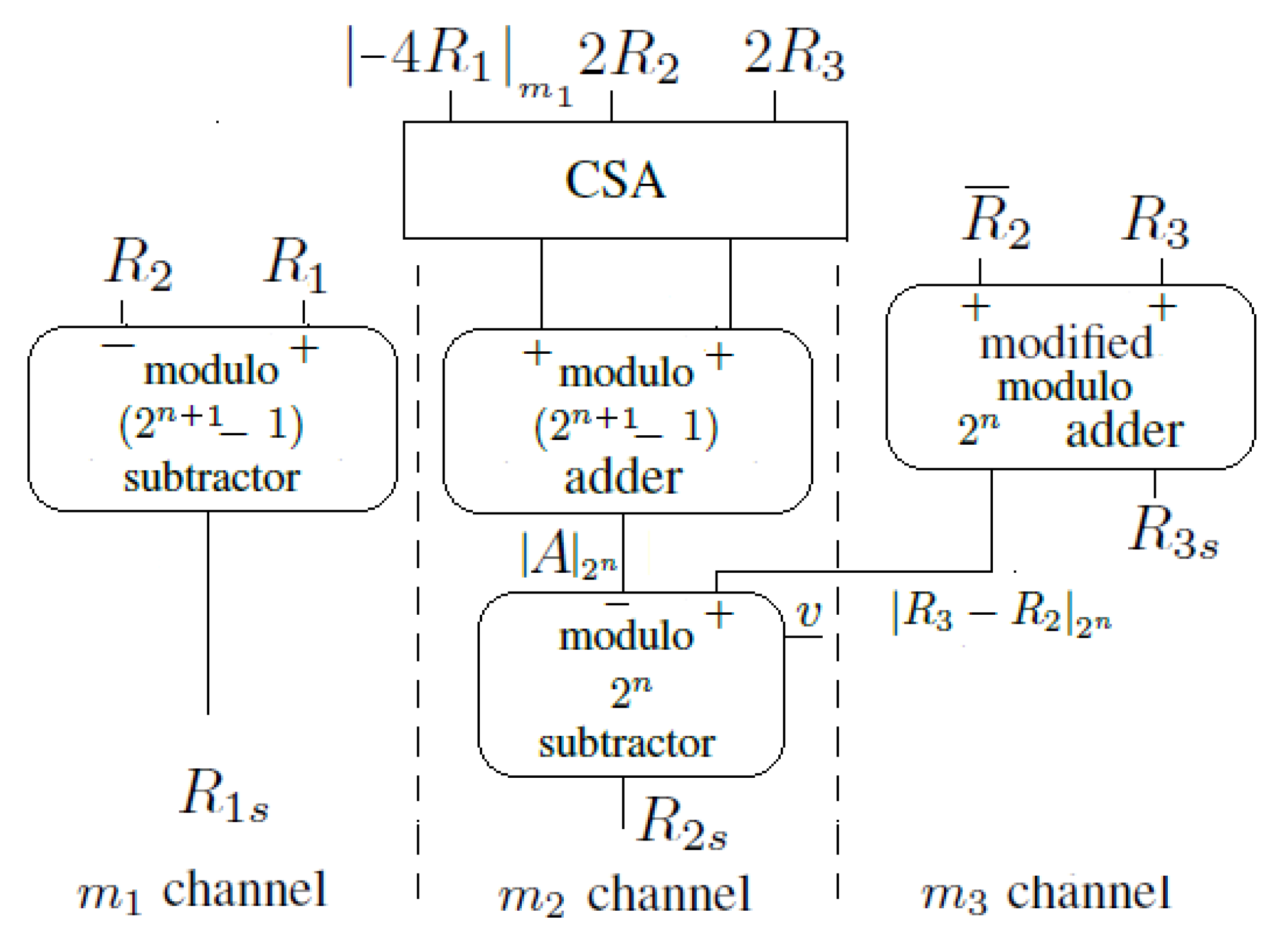
2.2. Hardware Implementation
The proposed hardware implementation of the CRT-based scaler of the moduli set is shown in Figure 1. The carry-save adder (CSA) of Figure 1 consists of full adders operating in parallel. The modulo adder, modulo subtractor, and modulo subtractor are described thoroughly in [19]. The modified modulo adder is described in the last paragraph of this section.
Figure 1.
The proposed scaler of the moduli set .
It is important to mention the modulo properties, where p is a positive integer [1]. The first property states that is performed by rotating the binary representation of a to the left k-bits, where a and k are positive integers and . The second property states that is performed by obtaining the 1’s complement of a. Therefore, the value of , applied to the CSA of Figure 1, is computed by rotating the binary representation of 2 bits to the left and then taking the 1’s complement of the rotated value. Assuming the binary representation of is given by , then , where the overline denotes the complement of the bit . However, in the channel of Figure 1, is obtained by rotating the output of the modulo adder 1 bit to the left.
The modified modulo adder in the channel is a binary adder that adds to . The modified adder is built as follows: The output of the parallel prefix structure of the adder is directed into two different and parallel tracks. In the first track, a 1 is added as an input carry to the output of the parallel prefix structure to produce . In the second track, the output carry, , of the parallel prefix structure is reinserted and added as an input carry to produce (i.e., [14]). A few additional gates (not shown in Figure 1) are used to verify if the condition v is true. The result of this verification is inserted as an input carry to the modulo subtractor in the channel. This input carry bit is injected into the least-significant prefix operator [19,20].
3. Comparison and VLSI Realization
There is no scaler published in the literature for the moduli set . The new proposed scaler was compared with the most recent and efficient published scaler of the traditional moduli set [12,13]. The unit-gate model was used as a basis for theoretical comparison [14]. All two-input monotonic gates had an area of 1 unit and a delay of 1 unit. The XOR (Exclusive OR) and XNOR (Exclusive NOR) gates had an area of 2 units and a delay of 2 units. However, the inverters were ignored. The full adder had an area of 7 units and a delay of 4 units, while the half adder had an area of 3 units and a delay of 2 units. The modular adder has an area and delay of and , respectively [19,20]. The area and delay of a binary adder are and , respectively [19,20]. The modified modulo adder has an area and delay of and , respectively [19]. However, the area and delay of the modular adder are and , respectively [20]. Table 1 lists the area and time delay requirements of the proposed scaler and those in [12,13].
Table 1.
Hardware and time requirements of the scaler proposed in this paper for and of the scalers proposed in [12,13] for .
To obtain a more precise estimation of the area, delay, and power for the three designs under consideration, all the structures were modeled in Verilog HDL(Hardware Description Language) for values of and 30. Synopsys Design Compiler (G-2012.06) was used to synthesize the designs and map them into 65 nm Synopsys DesignWare Digital Logic Libraries. The “place-and-route” phase was performed using the Synopsys IC Compiler. The Synopsys Power Compiler was also used to estimate the power consumed. Moreover, the Synopsys Simulator was used to verify the correctness of the design functionality. The results are shown in Table 2. The relative differences between the three designs (i.e., the proposed scaler [12,13]) are listed in Table 3. Compared to the scaler of [12], Table 3 indicates that, on average, the proposed scaler had a area and power reduced by and , respectively. The proposed scaler had, on average, an increased time delay of . Compared to the scaler of [13], Table 3 shows that the proposed scaler required a slightly smaller area and power, by and , respectively. However, it required an average time delay increase of . Nevertheless, as mentioned in Section 1, avoiding the MAC unit and replacing it with the MAC unit saves a very significant processing time [18].
Table 2.
VLSI (Very Large Scale Integration) implementation results of the proposed scaler of the moduli set and the scalers of [12,13] of the moduli set .
Table 3.
Relative performance of the proposed scaler compared with [12,13].
4. Conclusions
This paper proposes the first scaler for the moduli set . When compared with the most recent and efficient scalers of the traditional three-moduli set , the proposed scaler is proven to have an area- and power-efficient structure. However, the scalers of the traditional moduli set are more-time-efficient structures at the expense of having the modulo channel. Replacing the channel by the channel makes the proposed moduli set a faster alternative for RNS-based applications.
Funding
This research received no external funding.
Conflicts of Interest
The author declares no conflicts of interest.
References
- Soderstrand, M.A.; Jenkins, W.; Jullien, G.; Taylor, F. (Eds.) Residue Number System Arithmetic: Modern Applications in Digital Signal Processing; IEEE Press: New York, NY, USA, 1986. [Google Scholar]
- Hiasat, A. A suggestion for a fast residue multiplier for a family of moduli of the form (2n − (2p ± 1)). Comput. J. 2004, 47, 93–102. [Google Scholar] [CrossRef]
- Hiasat, A.; Khateeb, A. Efficient digital sweep oscillator with extremely low sweep rates. IEE Proc. Circuits Devices Syst. 1998, 145, 409–414. [Google Scholar] [CrossRef]
- Esmaeildoust, M.; Schinianakis, D.; Javashi, H.; Stouraitis, T.; Navi, K. Efficient RNS implementation of elliptic curve point multiplication over GF(p). IEEE Trans. VLSI Syst. 2013, 21, 1545–1549. [Google Scholar] [CrossRef]
- Sousa, L.; Antao, S.; Martins, P. Combining residue arithmetic to design efficient cryptographic circuits and systems. IEEE Circuits Syst. Mag. 2016, 16, 6–32. [Google Scholar] [CrossRef]
- Hiasat, A. Design and implementation of an RNS division algorithm. In Proceedings of the 13th IEEE Sympsoium on Computer Arithmetic, Asilomar, CA, USA, 6–9 July 1997; pp. 240–249. [Google Scholar]
- Ye, J.; Ma, S.; Hu, J. An efficient 2n RNS scaler for moduli set (2n − 1, 2n, 2n + 1). In Proceedings of the 2008 International Symposium on Information Science and Engineering ISISE, Shanghai, China, 20–22 December 2008; pp. 511–515. [Google Scholar]
- Hiasat, A.; Sweidan, A. Residue Number System to Binary Converter for the Moduli Set (2n−1, 2n − 1, 2n + 1). J. Syst. Arch. 2003, 49, 53–58. [Google Scholar] [CrossRef]
- Chang, C.H.; Low, J.; Yung, S. Simple, fast, and exact RNS scaler for the three-moduli set (2n − 1, 2n, 2n + 1). IEEE Trans. Circuits Syst. I 2011, 58, 2686–2697. [Google Scholar] [CrossRef]
- Low, J.; Chang, C.H. A VLSI efficient programmable power-of-two scaler for (2n − 1, 2n, 2n + 1). IEEE Trans. Circuits Syst. I 2012, 59, 2911–2919. [Google Scholar] [CrossRef]
- Tay, T.; Chang, C.H.; Low, J. Efficient VLSI implementation of 2n scaling of signed integer in RNS (2n − 1, 2n, 2n + 1). IEEE Trans. Very Large Scale Integr. Syst. 2013, 21, 1936–1940. [Google Scholar] [CrossRef]
- Sousa, L. 2n RNS scalers for extended 4-moduli sets. IEEE Trans. Comput. 2015, 64, 3322–3334. [Google Scholar] [CrossRef]
- Hiasat, A. Efficient RNS scalers for the extended three-moduli set (2n − 1, 2n+p, 2n + 1). IEEE Trans. Comput. 2017, 66, 1253–1260. [Google Scholar] [CrossRef]
- Zimmermann, R. Efficient VLSI implementation of modulo (2n ± 1) addition and multiplication. In Proceedings of the 14th IEEE Symposium on Computer Arithmetic (Cat. No.99CB36336), Adelaide, Australia, 14–16 April 1999; pp. 158–167. [Google Scholar]
- Hiasat, A.; Abdel-Aty-Zohdy, H. Design and implementation of a fast and compact residue-based semi-custom VLSI arithmetic chip. In Proceedings of the 1994 37th Midwest Symposium on Circuits and Systems, Lafayette, LA, USA, 3–5 August 1994; pp. 428–431. [Google Scholar]
- Hiasat, A. RNS arithmetic multiplier for medium and large moduli. IEEE Trans. Circuits Syst. 2000, 47, 937–940. [Google Scholar] [CrossRef]
- Muralidharan, R.; Chang, C.-H. Area-power efficient modulo 2n − 1 and modulo 2n + 1 multipliers for (2n − 1, 2n, 2n + 1) based RNS. IEEE Trans. Circuits Syst. I 2012, 59, 2263–2274. [Google Scholar] [CrossRef]
- Sheu, M.-H.; Siao, S.M.; Hwang, Y.T.; Sun, C.C.; Lin, Y.P. New adaptable three-moduli {2n+k, 2n − 1, 2n−1 − 1} residue number system-based finite impulse response implementation. IEICE Electron. Express 2016, 13, 20160090. [Google Scholar] [CrossRef]
- Kalamboukas, L.; Efstathiou, C.; Nikoloo, D.; Vergos, H.T.; Kalamatianos, J. High-speed parallel-prefix modulo 2n − 1 adders. IEEE Trans. Comput. 2000, 49, 673–680. [Google Scholar] [CrossRef]
- Vergos, H.T.; Efstathiou, C.; Nikolos, D. Diminished-one modulo 2n + 1 adder design. IEEE Trans. Comput. 2002, 51, 1389–1399. [Google Scholar] [CrossRef]
© 2018 by the author. Licensee MDPI, Basel, Switzerland. This article is an open access article distributed under the terms and conditions of the Creative Commons Attribution (CC BY) license (http://creativecommons.org/licenses/by/4.0/).
