Article

6DoF Object Tracking based on 3D Scans for Augmented Reality Remote Live Support

1
German Research Center for Artificial Intelligence (DFKI), Augmented Vision Department, 67663 Kaiserslautern, Germany
2
Bosch Rexroth AG, Research and Development, 97816 Lohr am Main, Germany
3
Robert Bosch GmbH, Corporate Research Department, 71272 Renningen, Germany
*
Author to whom correspondence should be addressed.
Current address: Trippstadterstr. 122 D-67663 Kaiserslautern, Germany
Computers 2018, 7(1), 6; https://doi.org/10.3390/computers7010006
Submission received: 30 November 2017 / Revised: 22 December 2017 / Accepted: 29 December 2017 / Published: 2 January 2018
(This article belongs to the Special Issue Advances in Mobile Augmented Reality)

Abstract

:
Tracking the 6DoF pose of arbitrary 3D objects is a fundamental topic in Augmented Reality (AR) research, having received a large amount of interest in the last decades. The necessity of accurate and computationally efficient object tracking is evident for a broad base of today’s AR applications. In this work we present a fully comprehensive pipeline for 6DoF Object Tracking based on 3D scans of objects, covering object registration, initialization and frame to frame tracking, implemented to optimize the user experience and to perform well in all typical challenging conditions such as fast motion, occlusions and illumination changes. Furthermore, we present the deployment of our tracking system in a Remote Live Support AR application with 3D object-aware registration of annotations and remote execution for delay and performance optimization. Experimental results demonstrate the tracking quality, real-time capability and the advantages of remote execution for computationally less powerful mobile devices.

1. Introduction

As Augmented Reality (AR) reaches its technological maturity, its potential is unveiled by applications in a variety of fields such as industrial construction and maintenance, education, entertainment and medicine [1,2,3,4,5]. New challenges have emerged such as photorealistic rendering, collaborative augmented reality, content authoring and sharing, reduction of motion-to-photon delay for head-mounted displays [6,7,8,9].
Still, accurate 6 Degree of Freedom (6DoF) camera localization corresponding to its position and orientation in the application coordinate system remains the main enabling technology for Augmented Reality as it allows for realistic placement of virtual objects in the real world, integration into it and interaction with it [10]. Traditionally, tracking approaches relied on localization of handcrafted targets such as fiducials or natural features of 2D images rich in texture [11,12]. These approaches were however considered obtrusive for the scene while limiting an application to the visibility range of the tracking target and being very sensitive to occlusions of that target. Two different directions exist, attempting to alleviate the need for markers, namely model-based tracking and simultaneous localization and mapping (SLAM) approaches.
SLAM approaches attempt to tackle the challenging problem of estimating the camera pose from features in its environment while simultaneously learning the 3D structure of this unknown environment. The seminal work in monocular visual SLAM was the Extended Kalman Filter (EKF) based MonoSLAM [13], which was followed by a large amount of significant publications in the field [14]. PTAM [15] reduced the computational cost of SLAM by splitting the tracking and the mapping parts to two different threads. Thus the computationally more costly mapping thread can run at a lower frequency without affecting the tracking which has to be real-time. Additionally, PTAM introduced Bundle Adjustment(BA) methods in visual SLAM for mapping optimization. ORB-SLAM [16] followed the same principles but extended the application area coverage capabilities by effective map management and loop closure techniques. SLAM systems have shown impressive results in uncovering the structure of their environment and are suitable for placing 3D virtual objects in a specific location of the scene, especially if they reconstruct a dense map of the environment. An example of a system that efficiently employs a SLAM algorithm for localization in AR is the Microsoft HoloLens.
The main advantage of SLAM tracking for AR being that it is not dependant on any predefined targets, can also be seen as a disadvantage is some cases. In particular, it is difficult to extract real-world scale information in SLAM and most importantly it is not directly possible to display object specific AR content, which is often an important trait of an AR application. In this case, model-based tracking of specific objects can be more suitable.
Model based tracking refers to using a predefined CAD line model or a 3D reconstructed textured model of the tracking target (e.g., object, room) and matching that to the live view of the object during tracking in order to uncover the 6DoF pose. This allows to alleviate the use of disruptive markers as the object itself is used as the target, while retaining full 3D information of the tracked object thus automatically providing the correct coordinate frame for AR augmentations. 3D CAD line models were used in [17] to perform tracking by minimizing the error between the lines of the observed object and its model in an iterative optimization approach. In [18], multiple hypotheses for the object pose were added in order to deal with ambiguities arising from object symmetries. Fusion of line tracking with texture features was proposed in [19] to increase the overall robustness. Textured 3D rendering is used in [20] to extract edge features from depth and texture discontinuities. Color information was used as a complementary tracking cue to the geometrical features in [21]. The aforementioned approaches can be regarded are computationally quite intensive as these systems operate in relatively low frame-rates. Especially the iterative optimization of CAD line model tracking can be cumbersome. Furthermore, these systems have a quickly deteriorating performance in cluttered environments. Initialization of the tracking is also often problematic in CAD-based systems as the user is asked to align an initial pose of the line model to the actual objects. This is time-consuming and requires a certain level of user expertise. Direct methods that have emerged more recently use the entire image instead of specific features and attempt to maximize the photometric consistency between frames. Examples of such approaches are [22,23]. Direct methods are in general more sensitive to sudden illumination changes making them less suitable for many types of applications.
Concerning available commercial systems for object tracking, Vuforia [24] offers tracking of objects based on CAD models, which performs well but suffers from the previously mentioned manual initialization problem. For objects for which no CAD models are available, a scanning procedure is available by placing objects next to markers and performing a structure-from-motion approach to uncover the 3D structure of the object. This again requires some level of user expertise and does not make the object model available for authoring of AR content with knowledge of the 3D structure.
In this article, we present a detailed version of the object tracking framework contained in [8]. The tracking is based on high quality textured 3D scans of objects and is designed to successfully address many of the challenges faced in 6DoF object tracking of arbitrary objects, namely fast and reliable initialization, robustness to motion blur and illumination changes and tracking during occlusions and in cluttered environments. The second part of the article presents a Remote Live Support application for industrial environments using the proposed 3D object tracker in an architecture consisting of the end user, a server and a remote expert utilizing edge computing for the tracking to ensure real-time performance independent of the end user hardware.
Being long time undiscovered for industrial use cases, Augmented Reality found its way onto the factory floor in recent couple of years. There exist plenty of solutions for different industrial use cases in which augmented or virtual reality is used [2]. Some examples are the training use case [25], marketing [26], assembly [27], remote live support [28,29,30] and many others.
The rapid evolution of industrial AR applications proves the success of the recent technological growth in the virtual and augmented reality world. Nevertheless, several crucial burdens remain unsolved. First, the existing AR hardware still lacks computational performance for delivering convincing AR experiences to the user. While running the demanding AR algorithms, devices such as glasses, smartphones or tablets suffer from overheating, unacceptably short battery life and further restrictions, for example regarding the quantity of renderable polygons [2]. Second, the process of designing, developing, deploying and maintenance of AR applications locally on different mobile devices is very expensive.
To combat these two issues, we propose a solution based on a real-time offloading of AR computations to a high performance server using Edge Computing. Edge or fog computing is a technology which brings computational resources and services closer to the end-device to reduce the added latency to a minimum, so that real-time applications are facilitated [31]. The so called edge server can take over the most heavy processing tasks that require CPU and/or GPU computations and provide a remote service to mobile devices in close proximity. This loosens up the limitations of mobile devices mentioned above and enables new types of services (e.g., augmented reality as a service).
On the other hand, this new architecture challenges the data transmission path between the client device and the edge server. Here, high data rates and short added latency are expected. The publically funded project “proWiLAN” faces these challenges by introducing a next generation radio technology for industry. A use case, considered in the project, applies Augmented Reality for industrial purposes implementing the Remote Live Support, where a field technician confronted with a machine error gets assistance by a remote expert through a video transmission and AR. This should increase the machine availability time as well as decrease the travel cost of qualified experts as it was shown that telephone support is frequently not enough to get the machine running again and a service engineer will most likely have to attend to it, which implies high expense through longer down time and travel cost [32].
In our use case, a field technician aka operator carries a head-mounted or handheld AR device, which is able to record a video stream of the user’s view—possibly along with other information, such as an audio stream, sensor data, etc.—and send it to a remote expert. The expert may be located anywhere and therefore may only be reached via a wide-area network (WAN), such as the Internet. The latency for the video and audio streams shall not exceed 250 ms and 150 ms respectively [33]. Observing the received video stream, the expert gives precise advices adding extra information aka annotations to the live stream. These annotations are shown in the operator’s glasses at proper positions, so he can easily follow the instructions. An accurate positioning is required along with some complex AR computations. The AR computations are offloaded (e.g., by using mobile edge computing concepts) to a server [34]. The end-to-end latency, which includes the recording of a new image, its transfer to the server, the necessary AR computations (e.g., tracking and rendering) and the transfer back to the client device, should not exceed 20 ms in the best and 70 ms in the worst case. In order to support future AR devices with 4 K resolution and stereo cameras, data rates up to 500 Mbps (in case of H.264 encoding) and up to 6.6 Gbps (in case of uncompressed video stream) shall be supported. The jitter of the video transmission shall not exceed 20 ms [35].
As mentioned above, a couple of such AR Remote Live Support applications have already been implemented [28,29,30], but most of them do not make use of a proper tracking method, so the annotations made by the remote expert are not registered correctly in 3D according to Azuma’s initial definition of AR [36]. These solutions are either solely showing augmentations in a 2D static manner [37] or they use outdated methods like marker tracking [30,38]. Recently, in [39] a Remote Live Support system was presented based on a client-server architecture that uses the Vuforia tracking framework but requires user collaboration in setting up the tracker by taking pictures from different views around the object. Additionally, it seems that the annotations of the expert are not registered in 3D but in 2D since the geometry of the objects is not fully known. Finally, [40] focuses more on the different mechanisms for capturing knowledge of the expert and transferring it to a person being trained on a task.
We identify the main drawbacks of previously existing methods in the tracking and 3D registration of annotations part. One reason for that are the above-mentioned insufficient computational resources of mobile AR devices. In this work, we combat this limitation by offloading the computation to a close edge server as shown in the next sections. In our use case, the most challenging processing task is represented by the object tracking mechanism that delivers the basis for the proper 3D augmentation.
The main contributions of this work are:
  • A robust 3D object tracking framework based on textured 3D scans of the objects
  • A fast and robust multi-threaded initialization and reinitialization scheme using ORB features
  • Frame to frame tracking with combination of tracking between real images and tracking between rendered and real images for additional robustness
  • The use of the pencil filter for the enhancement of illumination invariance of the tracking
  • A Remote Live Support architecture with 3D registration of the remote expert annotations
The rest of this article is organized as follows: In Section 2 we describe in detail the proposed object tracking pipeline. Subsequently, in Section 3 we provide the architecture of our Remote Live Support AR application using Edge Computing. Finally, in Section 4 we provide qualitative and quantitative experimental results on the tracking accuracy and runtime performance together with an evaluation of on the network-induced delays from offloading the tracking computations to an edge server.

2. 3D Object Tracking

In this section we present our proposed 3D object tracking pipeline. After defining the mathematical notation that will be used throughout this work in Section 2.1, we describe the preparatory steps for an object to be used for tracking in Section 2.2. Subsequently, we describe the tracking algorithm itself in Section 2.3. The overall algorithm flow chart is given, and the modules for initialization and re-initialization as well as the frame-to-frame tracking are presented in detail. Finally, the use of the pencil filter to increase the resilience of the tracking to illumination changes is advocated.

2.1. Problem Formulation

The addressed problem of 6DoF camera pose tracking consists of estimating a rotation matrix R c w R 3 × 3 representing the rotation from the world coordinate system W to the camera coordinate system C, and a translation vector W c R 3 containing the position of the world coordinate system origin in the camera coordinate system. In the case of object tracking the coordinate system of the object model can be considered as the world coordinate system W. Using a homogeneous representation of 3D points P R 4 in the object coordinate system and a homogeneous representation of 2D points p R 3 in the camera image coordinate system, the camera pose estimation problem requires an estimation of the camera pose [ R c w | W c ] such that the mapping
p = K [ R c w | W c ] P ,
best fits a set of known 3D to 2D correspondences M = { P i p i } , K R 3 × 3 representing the camera instrinsics matrix.

2.2. Object Registration Procedure

In this section the procedure that is followed for preparing an object so that it can be tracked by our algorithm, from the 3D Reconstruction of the object in Section 2.2.1 to the learning of the most suitable feature points for tracking in Section 2.2.2 is described.

2.2.1. 3D Scanning

Our tracking algorithm partially uses a 3D representation of the object. Therefore, it is important to be able to scan the object and generate a 3D model with a realistic texture. Our 3D reconstruction method is based on the structured light principle used in [41]. In this method, correspondences between the acquisition devices are generated by projecting patterns on the object. In our case, a phase shifted structured light is used, where two phase functions are transmitted from one projector to two cameras by encoding them into sinusoidal fringe patterns that are shifted a number of times. The phase functions are recovered in the camera images using a least square approach [42]. Thanks to the phase shifting, the number of reconstructed 3D points does not depend on the natural texture of the object and even objects with very poor texture can be reconstructed. Using one projector and two cameras, only one face of the object can be reconstructed. In order to reconstruct the entire object, the structured light method is repeated several times, creating a number of partial scans of the objects. These partial scans are merged together using the Iterative Closest Point method (ICP) [43]. In addition, images under natural illumination are taken for reconstructing the texture of the object. The reconstructed object can be stored efficiently in a small-size 3D model by using the method of [44]. Using this method, the mesh geometry is simplified into a shape proxy and the fine geometry variations are stored in a normal map. This way, the 3D model can be very precise and lightweight.

2.2.2. Learning Features for Tracking

Once a 3D model of the object is available, we can use it directly as input to a module that extracts automatically the most salient points on the object’s surface. To this aim, we use an offscreen renderer that can render the object with a given pose on an image of a predefined size. We generate a high number of random poses of the renderer camera around the object (usually in the order of magnitude of 10.000 poses), with a distance automatically adjusted so that the object keeps a given size in the image. Figure 1 shows several examples of the generated images. In addition, the renderer provides a depth image which provides for each pixel the distance of the object to the camera. With the offscreen renderer as a tool, we collect the points that have statistically the highest probability to be found by a point detector by using an accumulator. For each new random pose [ R c w | W c ] , we run a point detector on the rendered image. In our implementation, we opted for the Good Features To Track detector of [45], but any salient point detector can work. For each found point, we can recover its 3D coordinates by using the depth image generated by the renderer. In detail, if p = [ x , y , 1 ] is the 2D homogeneous representation of the point (pixel coordinates of the feature center) and z the depth obtained from the z-buffer of the renderer then the 3D position P of the object is defined as:
P = R c w T ( K 1 p ) z W c .
These 3D coordinates are put in a discrete 3D accumulator with a bin size proportional to the size of the object. Typically, we have a bin size of a few millimeters. This procedure is repeated a fixed number of times, or until enough points have been collected. We then run a Non-Maximum Suppression on the accumulator to avoid having too many points around a specific location, and sort the list of points according to the number of hits in the accumulator. We then keep the best points as a list of salient 3D points for the object, which we call anchor points. The green points in Figure 1 show some of the detected anchor points for one specific object.
Apart from the registered 3D points, a number of N o r b rendered images of the object are created, and ORB features are extracted and stored together with their corresponding 3D positions to be used as reference images for the ORB Initializer module (see Section 2.3.3).

2.3. Object Tracking Algorithm

In this Section, the core part of the our proposed object tracking algorithm is described. We first present the outline of the algorithm along with a flow chart to focus on the interplay of the different modules in Section 2.3.1. Subsequently, we describe in detail the frame-to-frame tracking (Section 2.3.2) and the initialization modules (Section 2.3.3). Finally, we describe the pencil filter and its importance for illumination resilient tracking.

2.3.1. Algorithm Outline

A flow chart of the tracking algorithm is given in Figure 2. The left side of the graph depicts the normal frame-to-frame tracking mode (Section 2.3.2) and the right side represents the procedure followed when initialization (Section 2.3.3) is required, i.e., when the frame-to-frame tracking fails or when the tracker application is started. In the frame-to-frame tracking mode, an off-screen rendering step is first performed, meaning that the 3D model of the tracked object is rendered using the pose [ R c w | W c ] k 1 from the previous frame k 1 . Subsequently, the rendered frame from k 1 together with the real frame k 1 are both used for matching to the current frame k. Matching is performed by optical flow between image patches around the registered anchor points of the object, assisted by the use of the pencil filter (Section 2.3.4). Using the acquired 3D-2D correspondences from the matching, the new pose for frame k, [ R c w | W c ] k is estimated by solving the perspective PnP problem within a RANSAC framework for outlier rejection [46].
The initialization part of the algorithm is activated whenever a correct pose for the previous frame k 1 is not available. It consists of two main modules, namely the ORB Initializer and the ORB Reinitializer. The ORB Reinitializer is a quick reinitialization scheme that is meant to quickly intervene whenever a failure of the frame-to-frame tracking occurs in order to recover a correct pose. It functions by matching ORB features of the current frame to a keyframe of known pose that is constantly being renewed by a background thread while frame-to-frame tracking is functioning. If this quick reinitialization step fails or if no keyframe is available yet, the ORB Initializer module is used. This module performs matching of ORB features to a number of rendered frames created and stored during the registration of the object. The procedure is accelerated by parallelization. The matching of the current to the registered frame that provides the most correspondences is used for pose estimation. In case of failure initialization is attempted again on the next frame.

2.3.2. Frame to Frame Tracking

The aim of the frame-to-frame tracking module is to follow individually the 2D position of the anchor points from one frame to the next one, and to compute a novel pose using the new 2D positions. It is assumed that the pose of the object in the last frame [ R c w | W c ] k 1 is known (by initialization or because the frame-to-frame tracking delivered a valid pose for the last frame). The general idea is to follow the point using a Kanade-Lucas-Tomasi (KLT) tracker [47], which is an iterative registration technique based on the texture of the neighborhood of a point. However, using a KLT tracker for many frames will inevitably lead to drift. In order to avoid the drift, we correct the position of the point by using a two-step approach: first, we follow a 2D point from the last video frame to the new video frame by using a standard KLT tracker. This is named Frame to Frame (F2F) tracking. In a second step, we use as reference a rendered version of the last frame. This rendered version is produced by an offscreen renderer, using the last valid pose. This way, we have a ground truth appearance for the point being tracked. The second step starts the iterative tracking from the position where the first step ended, but using the rendered image as reference for the template. We name this Rendered-to-Frame (R2F) tracking. This method allows for tracking points over a long period of time without drift. In practice, we repeat this tracking for all the points, but have to render the object with the previous pose only once per frame. The KLT trackers can run in parallel for many points.
Once the tracking in 2D converged, we end up with a new 2D position for all the visible anchor points. Because we know the 3D position of all the anchor points, we can use the 2D-3D correspondences to compute a new pose [ R c w | W c ] k for the new frame k. In order to avoid corruption by possible outliers, a RANSAC framework is used and only the inliers are kept.
If the KLT tracking fails for one of the anchor points, or if one of the anchor points is detected as outlier in the pose computation, its 2D position cannot be considered as valid anymore. A common cause can be a temporary occlusion of this point by another object, the user, or through self-occlusion. In these cases, the outlier points are marked as such, and in the next frames, their 2D position will be recomputed using the pose of the object and the 3D position of the point. With this technique, we can recover from temporary occlusion as soon as the occlusion stops.

2.3.3. ORB Initializer and Reinitializer

The frame-to-frame tracking will inevitably fail in some situations when not enough matches are found between consecutive frames due to e.g., motion blur. Additionally, an accurate initial pose of the object without previous pose knowledge is required when the tracker is started at first. In these cases it is very important for the user experience that the tracking system has the ability to initialize and reinitialize in a quick, seamless and robust manner that does not require any effort from the user side. To ensure that, we developed a two stage reinitilization and initialization procedure that is immediately activated upon a failure of the frame-to-frame tracking.
The ORB Initializer matches ORB [48] keypoints between the current frame and a number of N o r b rendered frames with known poses that are created and stored during the registration procedure of the object (Section 2.2). The matching procedure for all frames is split among all available threads and done in parallel. This allows to match to a large number of registered frames (up to 64) in a considerably short time. To discard potential outliers the matches from the descriptor sets of each reference rendered image are first subjected to a ratio test between the first two possible matches as suggested in [49]. Subsequently, the reference image that produced the highest number of good matches (i.e., matches that withstood the ratio test) among all reference images is used for pose estimation utilizing correspondences of registered 3D points from the reference image to 2D image points from the current frame and solving the perspective PnP problem in a RANSAC framework.
The ORB Reinitializer is implemented to directly intervene whenever the frame-to-frame tracking fails to rapidly regain the correct pose. It is based on an alternative deployment of the concept of keyframes borrowed by SLAM tracking systems. During the normal function of the frame-to-frame tracker a background thread running at a lower frequency compared to the tracker is responsible for collecting and renewing a single keyframe. The keyframe contains an image frame, the pose resulting from the tracker for that frame and ORB feature descriptors extracted from that image along with their 2D image coordinates and their 3D position calculated from the pose. For a frame to be selected as a keyframe several criteria have to be fulfilled, to ensure that the tracking was functioning properly on that frame. The criteria used are that the ratio of outliers to inliers from the RANSAC procedure as well as the reprojection error of the tracked features should not exceed certain thresholds. Whenever the frame-to-frame tracking fails, the ORB Reinitializer matches the current frame to the stored keyframe in order to estimate the pose, similarly to the ORB Initializer. The Reinitializer module is highly effective because it usually matches between very similar frames, especially when the keyframe gets renewed at a high rate. In case of failure of the reinitialization, the ORB Initializer is used.

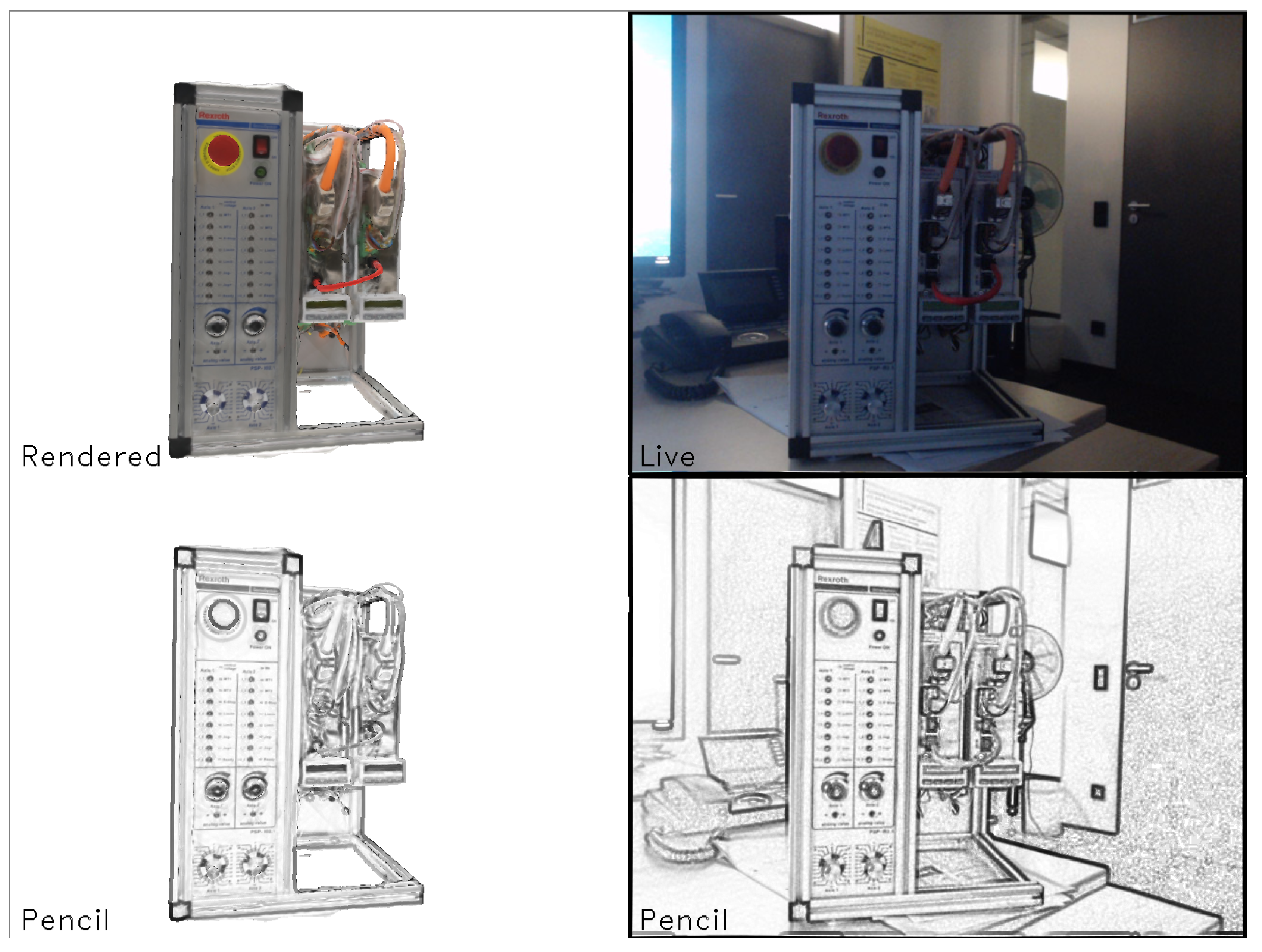
2.3.4. Pencil Filter

In order to make the frame-to-frame tracking more robust, especially to illumination changes we propose to preprocess the images by applying the pencil filter. The pencil filter is commonly used to add an artistic effect on images, however we found that its edge enhancing and image normalization properties are very beneficial for tracking image patches with our frame-to-frame tracker. The filtering procedure consists of a dilation of the grayscale image with an ellipse and then thresholding for local normalization of the pixel values. The result of the application of the pencil filter in an image can be seen in Figure 3. On the top two images the rendered model of the object and an image of the real object in a challenging illumination setting are presented. On the bottom two images the pencil image versions of the rendered and live object image are shown. It is clearly visible that the application of the pencil filter greatly increases the similarity between rendered and real image in this situation, making the frame-to-frame tracking more robust.

3. Remote Live Support Realized with Mobile Edge Computing

In the following chapter the Edge Computing architecture of our Remote Support Application will be described. Therefore a short introduction to Mobile Edge Computing is first given in Section 3.1, followed by the justification why this technology is so important for mobile AR. Afterwards a detailed insight into the application architecture is provided, describing the roles of all three main actors namely the end user (client), edge server and remote expert (Section 3.3). Finally, the proposed approach for 3D registration of annotations in the object coordinate space is presented.

3.1. Mobile Edge Computing

Multi-access Edge Computing (MEC) is a new official name for Mobile Edge Computing. With MEC, cloud-computing capabilities and an extensive IT service environment are offered at the edge of the network. The use of MEC in factory automation should enable processing of vast amount of data, complex orchestration of cyber-physical systems, and coordination of computation as well as communication resources in real-time [50]. For our work, MEC represents a promising approach to achieve the low latencies required for many industrial applications. MEC employs resource rich edge servers that are placed close to end devices and assist them in executing computation intensive tasks (e.g., complex data processing). The core element of MEC is the cognitive management entity that, among variety of tasks, ensures the advanced resource planning. To fulfil high industry requirements mentioned above, MEC enables further important techniques besides effective resource allocation and offloading [51]. These include caching, mobility support, service migration, data prioritization, etc. Many aspects of MEC are still in a very early development phase and are expected to continue evolving over the next years. In this paper, we focus on the offloading feature of MEC described in the next sections.

3.2. Relevance of MEC for AR

As described previously, Mobile Edge Computing can bring computing resources and services closer to the user and thereby offers huge advantages over cloud computing in terms of latency. Since most available mobile devices until today are not able to run the demanding AR algorithms such as those described in Section 3.1, MEC has the potential to be one fundamental building block for providing next generation AR applications.
Our proposed AR Edge Computing architecture consists of two main actors: The client (in the remote live support use case: the machine operator), who wants to get some augmented reality information superimposed on his perception of the physical world, and the edge server, which has the task to bring the AR experience to the user and therefore to run the computationally challenging AR algorithms. While the client device can be any mobile device having an integrated camera, the edge server should be a high-performance PC with an appropriate graphics card.

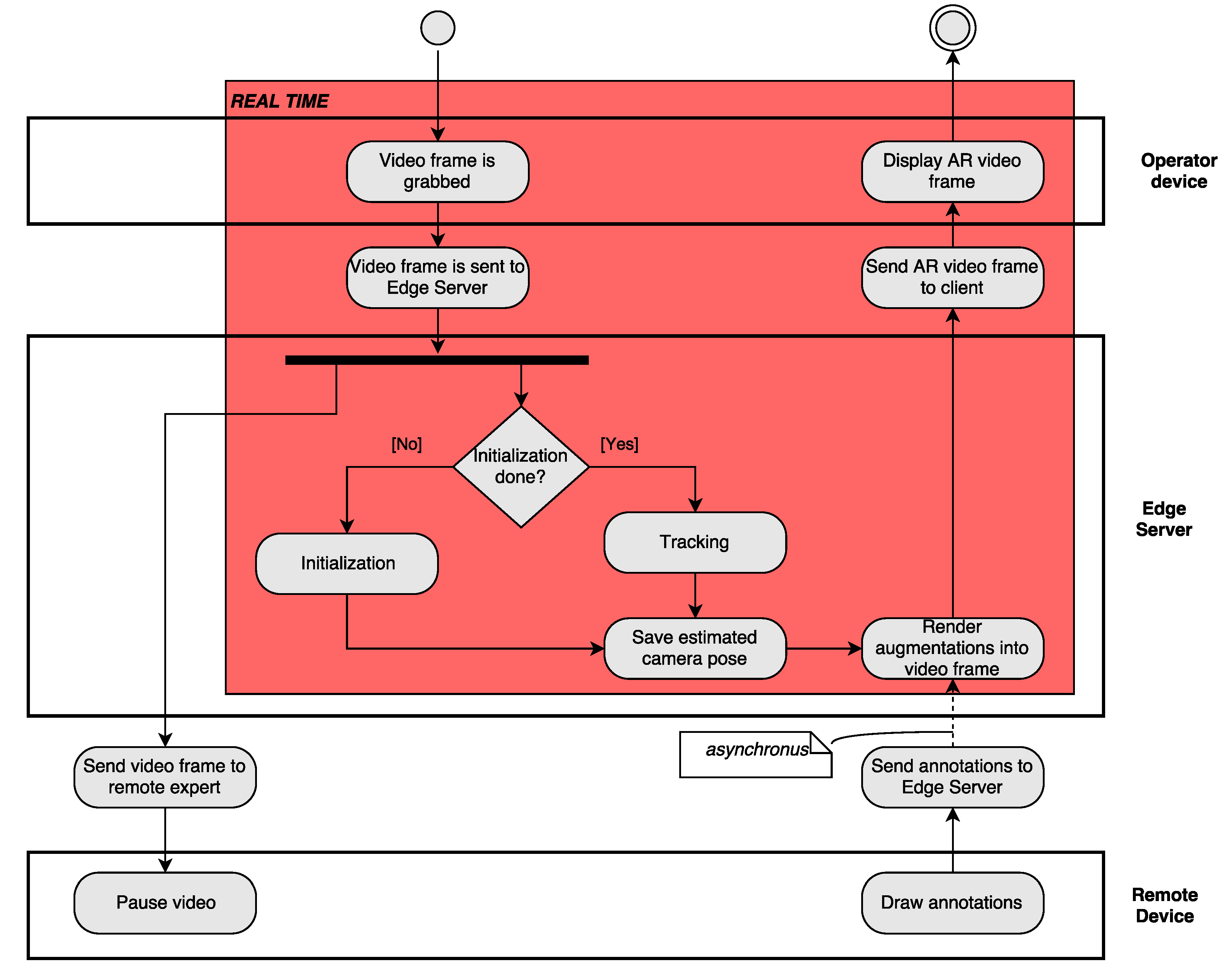
3.3. Remote Live Support System Architecture

3.3.1. Overview

In the remote live support use case a third instance comes into play, namely the remote expert. His task is to draw annotations into the video stream coming from the operator in order to support him. In such remote support scenarios the most common devices for the remote expert to use are a laptop or a tablet pc. The involved actors are shown in Figure 4.
Both the operator and the remote expert have to connect to the edge server before the periodic process illustrated in Figure 5 can start.
First, the operator’s mobile AR device camera grabs frames at a configured frame rate and sends them to the edge server. In our implementation we rely on a web application on the client side so the frames can either be sent via websocket or WebRTC. On the edge server the process is divided into two asynchronous sub-processes. On the one hand the server accomplishes the tracking algorithm (if the algorithm has already initialized), which was introduced in detail in Section 2.3. The estimated camera pose of each frame is saved on the edge server. On the other hand the server forwards the video stream to the remote expert. This second part of the process is not performed in real-time because available WAN infrastructure is used as the expert can sit thousands of kilometres away.
When the remote expert receives the incoming video stream he can pause it at any time to draw some helpful hints onto it, such as circles, arrows, text messages or freehand sketches. Those annotations are sent back to the edge server together with the corresponding picture ID, so the edge server is able to match the annotated picture with the saved camera pose. This way the annotations can be registered properly in 3D (see Section 3.3.5). As soon as new annotations are registered they are rendered into the video stream, which is sent back to the client permanently, regardless of whether annotations are available or not.
Attention should be paid to the fact that the cycle time between the grabbing of a camera frame to its augmented visualization (red background in Figure 5) has to be kept as small as possible. Experts estimate the maximum end-to-end latency a user wearing an HMD can perceive at 10 ms [52], where in some non-HMD applications considerably higher latencies are tolerable [53].

3.3.2. User Side—Mobile Device

The client device, which can be any mobile device having available an integrated camera and an up-to-date web browser, has to grab live data from the camera and send it to the edge server via web technology like web sockets or WebRTC. We found that with current WiFi technologies a client-side compression of the video stream (or single pictures) before transferring it to the edge server is faster than sending raw data. Depending on the chosen protocol, compression is done either manually (i.e., JPEG for web sockets or WebRTC DataChannel) or by the protocol (V8 with WebRTC MediaChannel). The incoming annotated video data are also to be displayed in the web browser.

3.3.3. Server Side—Edge Cloud

The edge server is the central component in our architecture. It is responsible for executing all algorithms and tasks which are computationally too demanding for the client device. In our implementation this corresponds to the object tracking and the rendering of augmentations. A constant stream of captured video is received from the user. To perform the explained object tracking an initialization step is required in the beginning or when tracking is lost as described in Section 2.3.3. Following a successful initialization the frame-to-frame tracking approach is used. The tracking on the edge server is integrated into a Unity3D application, which is also responsible for rendering the augmentations into the camera feed and sending it back to the client.

3.3.4. Remote Expert

The application on the remote expert side receives the video stream from the operator (sent via edge server). The remote expert then can pause the video stream to draw various annotations onto it, such as circles, arrows, text or freehand-sketches. Those can also be removed from the stream, when they are not needed any more. The annotations are finally sent back to the edge server. Since a Unity3D application was deployed on the edge server, we also use Unity3D for the remote expert application in order not to run into compatibility conflicts of the exchanged data.

3.3.5. 3D Registration of Annotations

One crucial task of the edge server is to render the annotations made by the remote expert correctly into the camera feed sent back to the machine operator. It must be emphasized, that the remote expert draws his annotations into a 2D picture, where the edge server has to register them in 3D, so the operator is able to walk around the machine experiencing the augmentations with proper translation, rotation and scale. In comparison to a 2D-based approach that assumes planarity of the scene, with 3D registration of augmentations we have direct connection of the AR content to the object through the knowledge of its 3D structure and can cover any motion of the user without incorrect augmentations or loss of tracking. An example of this is the correct placement of the red arrow pointing to the button on the machine of Figure 6 from different angles. Additionally, since the remote expert application freezes the image and draws on it asynchronously, it is expected that there could be a significant change in the end user camera pose in the meantime. Therefore, 3D registration of annotations with respect to the tracked object is an important issue to ensure the expected functionality of the application. The process is made up as follows: The remote expert receives the live video stream from operator’s AR device and pauses it at any time. Then he draws one or more 2D annotations into the frozen frame (e.g., a red circle like in Figure 7).
The prerequisite for the edge server to be able to position the annotation correctly is that it is drawn onto the known object (3D model of a machine used for tracking) and not in free space (grey space in Figure 7). Now the vector from image center to annotation’s fix point (e.g., the center of the red circle annotation) is calculated and normalized over the side lengths of the render view-port camera in the Unity3D application of the remote expert. This vector together with the frame ID of the freeze frame is sent to the edge server, which draws the same vector into the corresponding image (still 2D) on server-side. Since the video textures in the Unity 3D applications of the remote expert an the edge server can be of different size, the normalized vector first has to be multiplied by a scaling factor related to the side lengths of the render view-port camera of the edge server application. As we can see in Figure 7 a virtual camera is targeted at this 2D texture. Because the coordinates of this virtual camera in Unity are known, the vector between the camera and the annotation can be calculated.
Subsequently the camera pose computed by the tracking system described in Section 2.3 is then transferred to a second virtual camera targeting the 3D model of the object the machine operator wants to maintain (usually a machine). The vector calculated in the previous step is now transformed into the camera system of this second camera. As outlined in Figure 7 now a ray can be cast from the second camera in the direction of the anchor point of the annotation. The point, where this ray hits the collider of the 3D model can be assumed as the spot in 3D space the remote expert wanted to attach his annotation to.

4. Evaluation

In this section, we present experimental results of the proposed 3D object tracking algorithm as an entity but also within the remote live support application context. A qualitative evaluation demonstrating the robustness of the tracking at different scales, during fast motion, occlusions and illumination variation is followed by a quantitative analysis of the user-side translational and angular error of the 3D annotations placed by the remote expert in Section 4.1. Apart from the tracking accuracy, an equally important aspect of a tracking system is represented by the processing resources. For this reason, we compare the required time for tracking on a powerful desktop PC to the time required in a mobile device, and argue for the use of remote execution of the tracking and rendering of augmentations in Section 4.2. This claim is also supported by measurements of the network-induced delay for offloading the execution to a server.

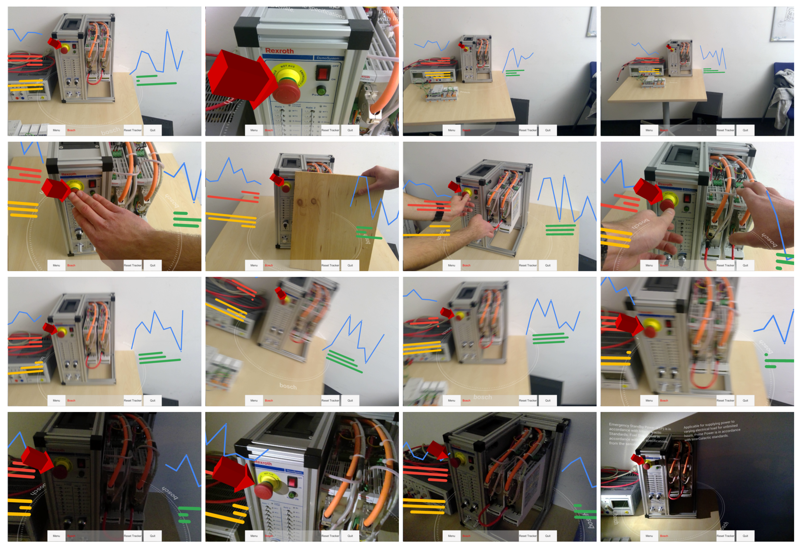
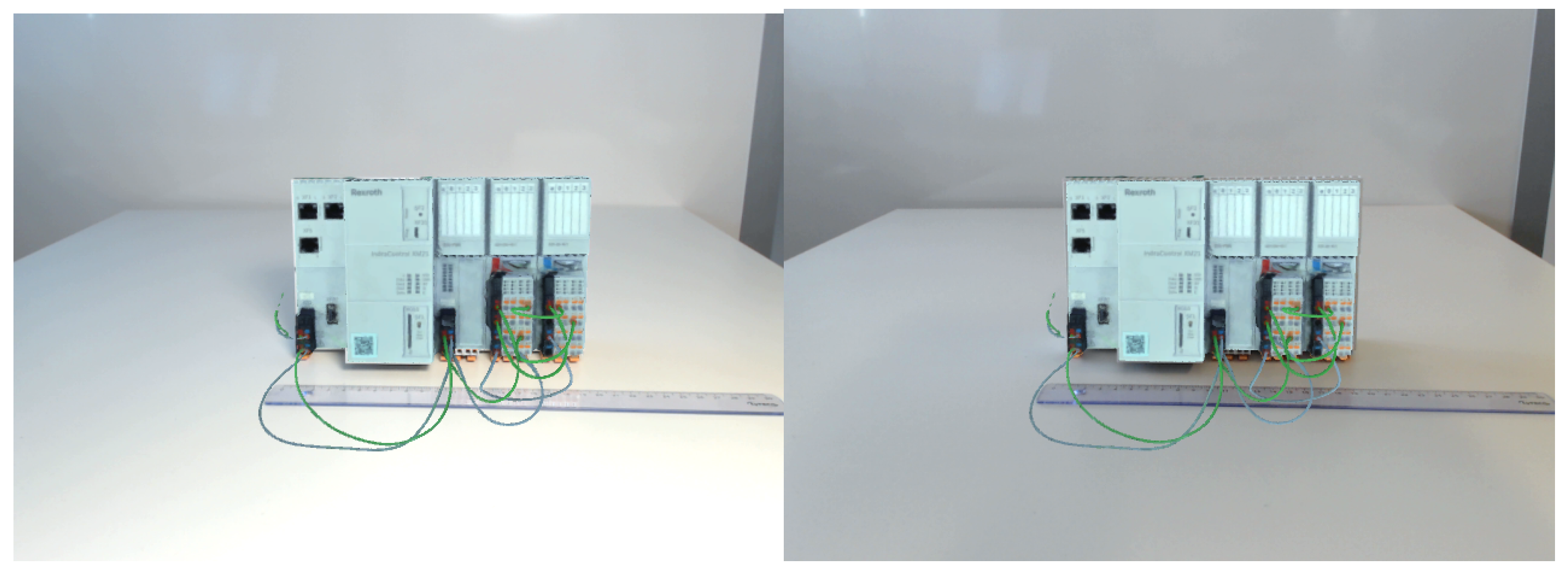
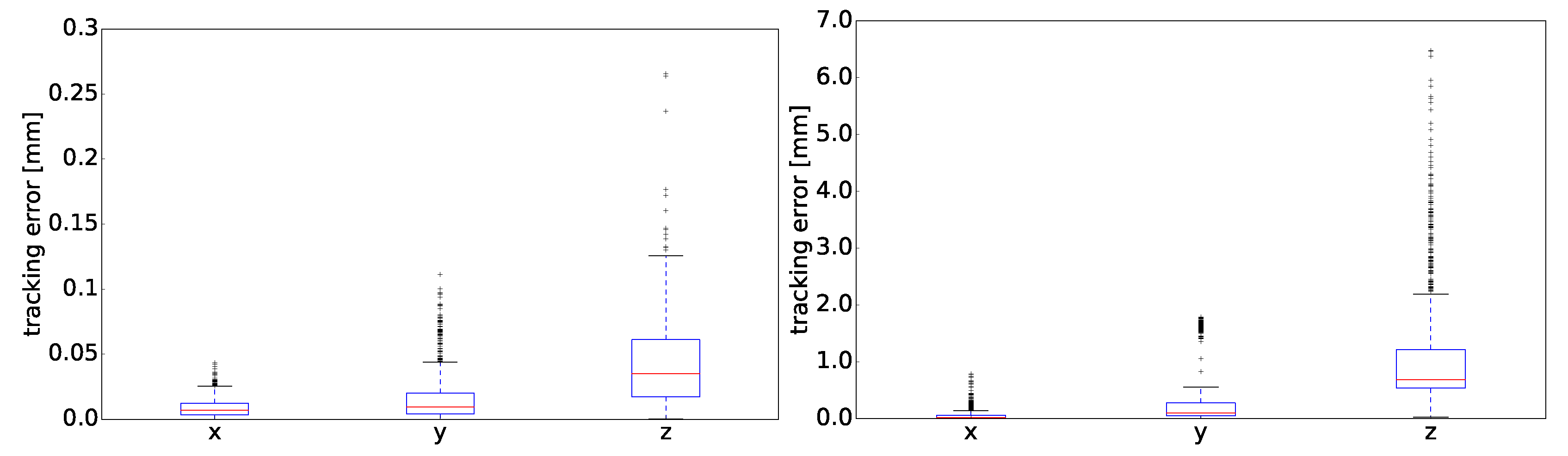
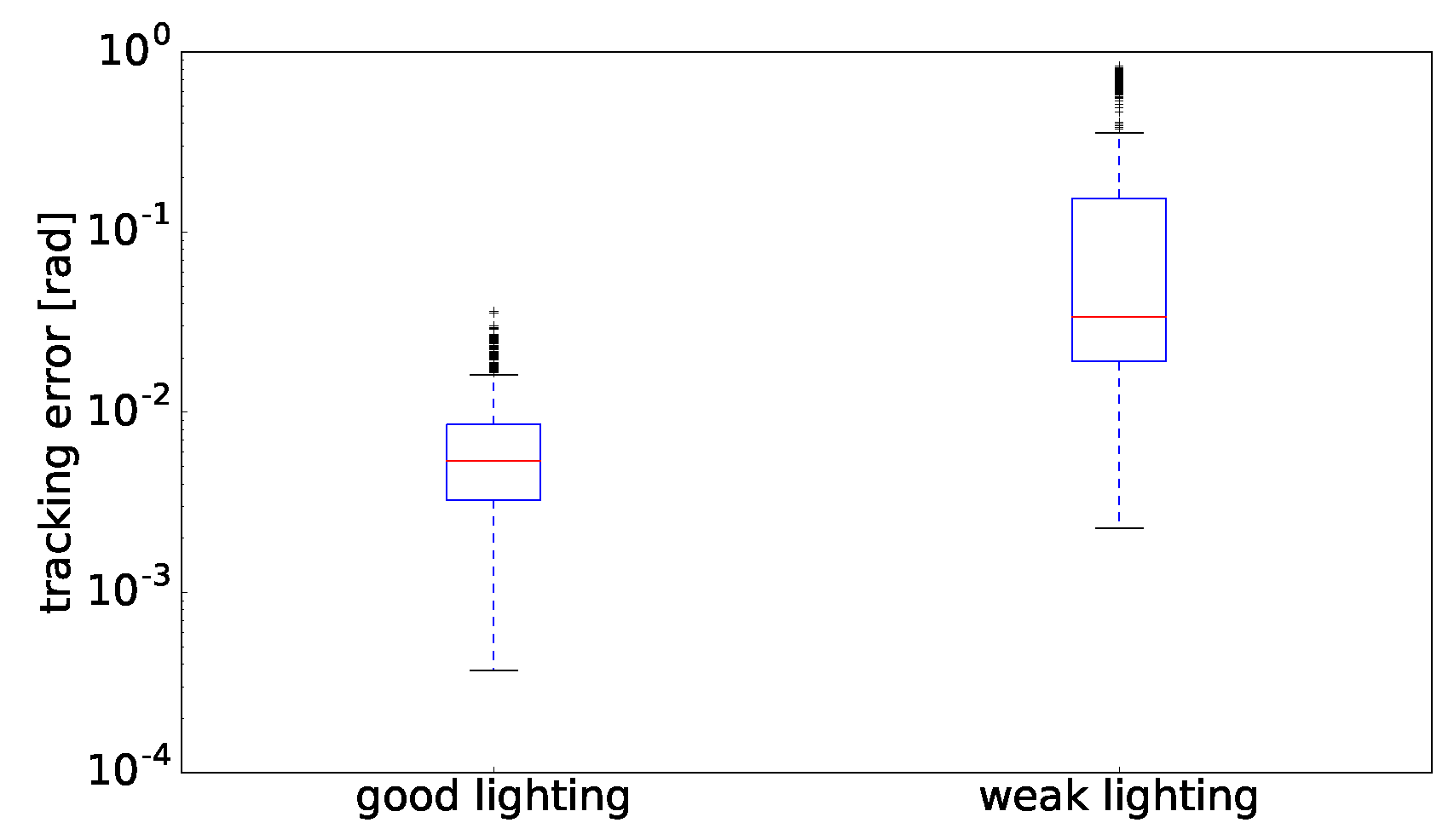
4.1. Tracking Quality

Figure 6 presents the behaviour of the tracking system under various challenging conditions. The tracking accuracy is qualitatively evaluated by observing the red arrow augmentation placement in 3D in the selected challenging image frames. In the first row of images, the range of scale at which an object can be tracked is presented. In the second row, the ability of the tracker to function properly under occlusions of the target object because of interaction with the object and with a partial view of the object is demonstrated. In the third row, we present robust tracking under severe image motion blur. Finally in the fourth row, we demonstrate the tracker resilience to illumination changes. Another requirement for the tracking system is that it is not affected by changes in the geometry of the objects. Indeed, in the presented results there are already discrepancies between the real objects and their 3D models. For example buttons that are in different states or cables that have been removed or connected differently. The use of keypoints of the model instead of a holistic optimization approach allows the tracking to be robust to these kind of changes the same way it is robust to occlusions.
Figure 8 demonstrates the improvement in tracking achieved through the use of the pencil filter. In the first row, images from tracking using histogram equalized grayscale images are shown, while in the second row tracking images using the pencil filter are presented. The inlier features from the RANSAC pose estimation step (Section 2.3.2) are marked green and the outliers are marked red. The optical flow matching vectors of features are marked with yellow color. It is clear that using the pencil filter leads to having much less wrong matches resulting in outliers, which in turn greatly enhances the stability of the tracker. Furthermore, since it makes the tracking much less dependent on the pixel intensities it also increases the robustness to changes of object appearance due to dirt and dust that may appear on it in a realistic industrial setting.
For the quantitative analysis of our object tracking solution, we present measurement results of the user-side translational and angular root mean square error (RMSE). For this, an augmentation of a 3D model placed on top of a real object has been assessed in a static scenario. We built a testbed using standard off-the-shelf hardware components: a desk lamp, Logitech C922 Pro webcam and control hardware IndraControl XM21 from Bosch Rexroth AG (Figure 9). Two different lighting conditions have been tested – good and weak lighting – using the desk lamp. The software was running on a standard HP ZBook 15 G2 (Code H9S03EC, i7-4810MQ 2.8 GHz, NVIDIA Quadro K2100M, 802.11ac, 32 GB RAM, 256 GB disk). We evaluated the tracking precision using estimation of the standard deviation from the pre-calculated ground truth tracking result. This ground truth represents the reference values for the accurate translation and rotation of the XM21 model manually placed on top of the real XM21 observed through a camera. In other words, we measure the jitter of the tracking system on different poses, since an external tracker with an accuracy that is clearly superior to the one of our tracker was not available.
In Figure 10 and Figure 11, the evaluation of the tracking performance is presented as translation and rotation errors correspondingly, for both lighting conditions and after the initialization phase of the object tracking was done. The error represents an absolute deviation from reference values. The translation is presented for all three dimensions separately. The results prove a very high accuracy of our tracking approach in good lighting conditions with errors below 0.1 mm for translation and 0.01 rad for rotation having just few outliers. In the weak lighting conditions, the tracking error increases approximately by a factor of 10. The performance, however, is still very high with errors below 1 mm for translation and 0.1 rad for rotation. This proves the robustness of the tracking approach in weak lighting conditions. Next, we evaluate the timing aspects of our tracking approach in a standalone setup as well as in combination with edge computing.

4.2. Runtime Measurements

In this section, we present an experimental evaluation of the application runtime. Results on the network-induced delay for the transmission of images to the edge server and back to the client are given in Section 4.2.1 whereas the comparison of running our tracking approach on different platforms is given in Section 4.2.2. The latter compares the server delay to the delay of a mobile PC in order to provide a justification for the use of server offloading in the remote live support application described above.

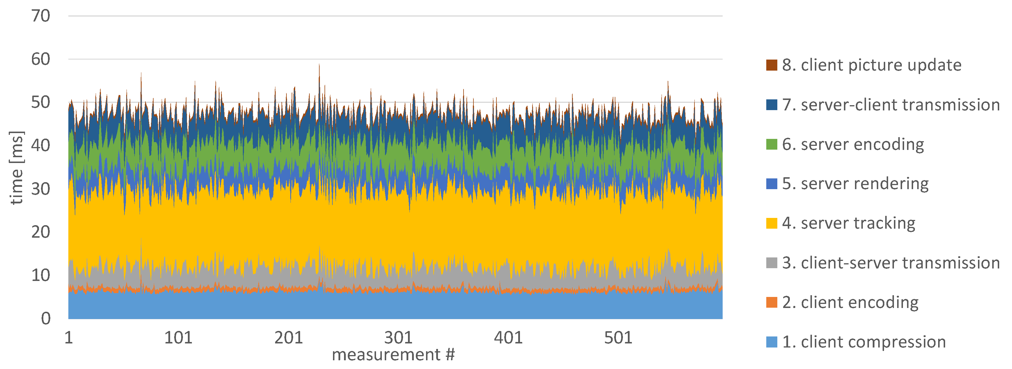
4.2.1. Offloading Delay

As mentioned previously, the offloading of 3D object tracking requires high data rates and short added latency in the communication channel between the server and the client. A typical architectural distance between a client and edge server should not exceed 2–3 hops to avoid additional store-and-forward delays. For the evaluation of the network delay, we built a testbed consisting of the following elements: a client (Microsoft Surface Pro 4 with an Intel Core i5 processor at 2.4 GHz and 8 GB RAM), a server represented by HP ZBook 15 G2 (see the detailed parameters above) and a WiFi router (TP-LINK Archer C7 AC1750, WLAN 802.11n mode, Gigabit Ethernet). We collected measurements in three different network setups: (i) client and server applications run on the server exchanging data over the localhost connection; (ii) client runs on the MS Surface, server—on the ZBook, both participants are connected over Ethernet cable to the router; (iii) same as in the second setup but the client is connected over WiFi to the router. The measurements results are presented in Figure 12, Figure 13 and Figure 14 correspondingly. For the transmission of video data, the following parameters have been applied: 640 × 480 image resolution, frame coding using JPEG at 75% and WebRTC protocol for peer-to-peer connection combined with UDP/IP stack. In the previous work of [2] it was found that JPEG compression of 75% gives a good trade-off between image quality and transmission time (image file size). We did not experience a deteriorated tracking performance on the compressed images in comparison to the uncompressed ones.
More than one thousand measurements have been conducted in each setup. To get a deeper view on different latency subcomponents, we split each measurement, using co-measured timestamps, into eight parts representing eight main system aspects that have the major impact on the overall latency. These aspects are: client compression, client encoding, client-server transmission, server tracking, server rendering, server encoding, server-client transmission and client picture update. We observed that the majority of delay components are very deterministic and have very little standard deviation. The most unstable values are achieved for the client compression, client-server and server-client transmissions. The time for the video compression on the client highly depends on currently available resources and the operation system status that show high variation over time. The transmission latency, being the most unstable in case of wireless connection, represents the biggest standard deviation.
Despite the challenging video transmission, the average round-trip latency remained below 70 ms even in the setup with the wireless connection. However, the identified aspects like the client-side frame compression and communication channel between client and server remain to be weak aspects of the offloading approach.

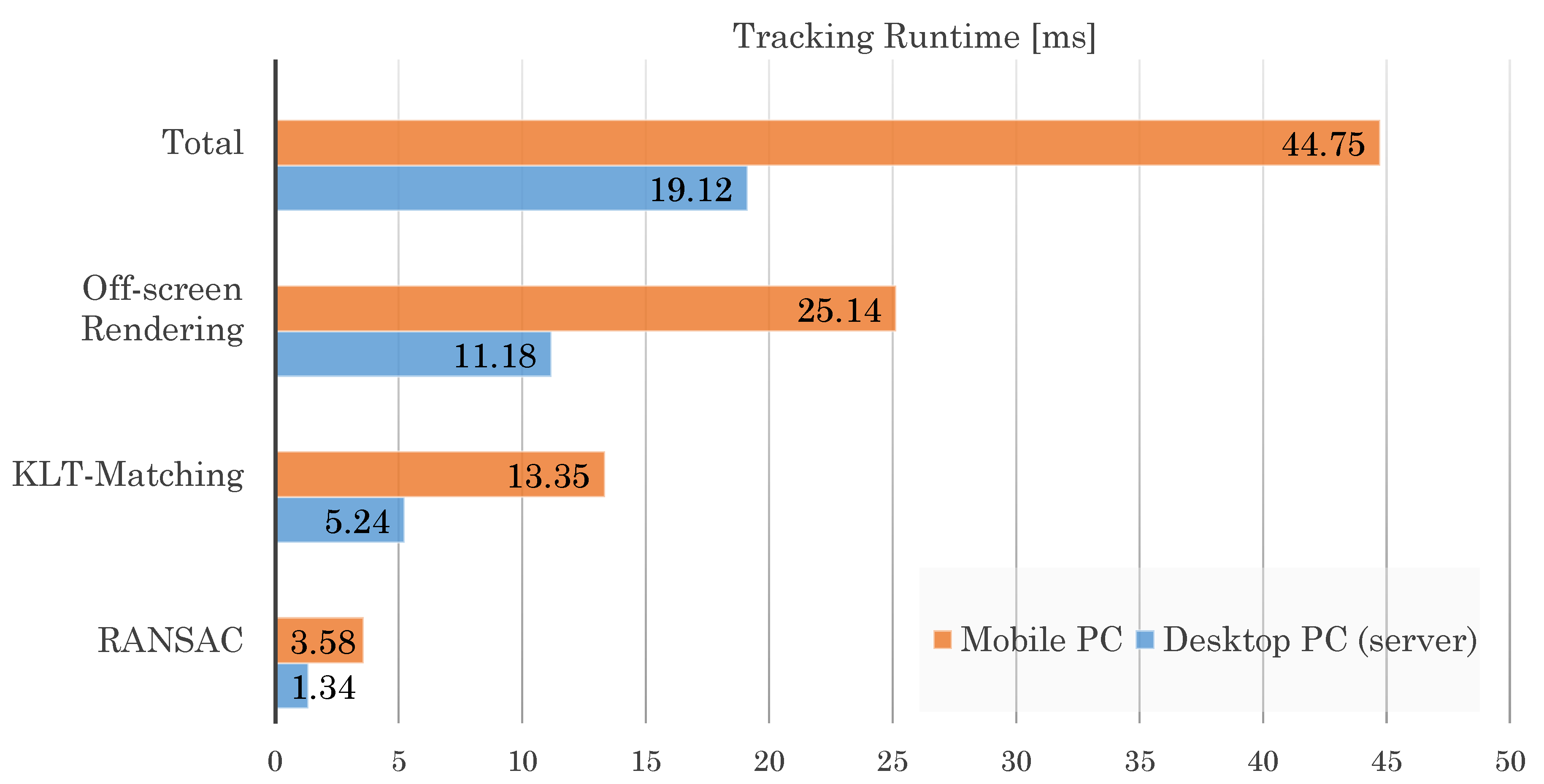
4.2.2. Server vs. Mobile Device Processing Time

The runtime performance of the proposed tracking algorithm has been evaluated on two different devices and is given in Figure 15. Firstly, a Desktop PC with an Intel Xeon processor at 3.7 GHz with 32 GB RAM and a GeForce GTX 1080 Graphics Card which is a good example of the kind of device an edge server in remote live support architecture could be. Additionally, in order to compare the server processing time to that of a typical end-user mobile device, we also evaluate the runtime performance on a Microsoft Surface Pro 4 (see the detailed parameters in the previous section). The comparison in Figure 15 was conducted for a 640 × 480 standard image resolution. The average time per frame for frame-to-frame tracking was computed excluding the time required for tracking initialization. The number of tracked features was set to 500.
As presented in Figure 15, the average runtime of the tracking algorithm on the server is 19.12 ms per frame, which corresponds to ≈52 fps. The latter easily covers the needs of most applications (i.e., most cameras on commercial devices and webcams offer up to 30 fps). In contrast to that, the runtime on the mobile SurfacePro is more than twice as much resulting at 44.75 ms. The achieved frame rate of ≈22 fps can still be considered adequate for an AR application, however two additional factors have to be taken into account. First, the used mobile device is a relatively powerful one, especially compared to e.g., a smartphone or a regular tablet. Second, one should consider the fact that the given values are for the tracking only and that additional computing resources will be needed for the rendering of AR content using the pose from the tracking. Therefore, it can be expected that the additional overhead will eventually lead to a visible slowdown of the application.
As can be seen in Figure 15, one of the main contributors to the overall delay is the off-screen rendering step which is highly dependent on the device graphic card. This step consumes more than half of the tracking time for both tested devices. Subsequently, the optical flow KLT matching is achieved quite fast since only a local search has to be done for each feature. The delay of this step depends of course on the total number of tracked features for the object and also the number of currently tracked features at each frame. It is possible to further reduce the matching time by reducing the number of tracked features, however, the amount of features chosen in this experiment is one that guarantees stable tracking from all poses of the used object. Finally, the required time for the RANSAC pose estimation can vary a lot depending on the number of RANSAC iterations that were applied. It is, however, kept very low most of the time because of the high ratio of inliers received from the KLT matching step.
Additionally to the frame-to-frame tracking runtime measurements, we also measured the time required for initialization and reinitialization using the approaches described in Section 2.3.3. Initialization of tracking using N = 64 rendered poses of the object as reference requires 80–120 ms on the Desktop PC and 110–160 ms on the mobile PC. Reinitialization is very fast requiring only 10.08 ms on average on the Desktop PC and 21.67 ms on the mobile PC. Fast reinitialization is one of the key features of the tracking system allowing it to recover immediately when a loss of the frame-to-frame tracking occurs.

5. Discussion

In this article, we presented a novel 3D object tracking approach based on textured scans. The use of textured 3D reconstructions of the tracked object geometry is motivated by the extra information that textured scans provide for tracking and especially for initialization compared to CAD models. Additionally to that there are objects that for which CAD models are not available by their manufacturers. In these cases, the object reconstruction pipeline based on structured light projection that is used in our work is a viable alternative to making an object directly trackable. Still, it should be mentioned that there are objects (e.g., highly reflective, completely textureless) that are not easily scanned with existing technologies nor do they offer enough features for tracking.
The focus of our work was on tackling the issues encountered in tracking under uncontrolled conditions to achieve the best possible experience of users with the system. We achieve illumination invariance of the frame-to-frame tracking through the use of the pencil filter, and robustness to motion blur through a seamless direct reinitialization procedure based on storing a tracking keyframe. The tracker is able to estimate a correct pose even under heavy occlusion of the target object because it relies on keypoints instead of employing a full model optimization procedure. The tracking quality is demonstrated in both qualitative and quantitative experimental results.
We present the integration of the object tracking algorithm in an industrial AR application of Remote Live Support. Through this, we address another issue of tracking systems, namely that of computing resources. We experimentally show that while the tracker operations are quite fast on a Desktop PC, a Mobile device of the kind that is expected to be used on an AR application such as ours is pushed to the limit of its performance leaving little room for other applications and consuming too much battery. Because of this, we suggested the remote execution of the tracking within an edge computing architecture instead of the mobile end device and show how that can positively influence the application by reducing the total delay of the tracking taking into account the network delay for the transmission of images to the server and back.

Acknowledgments

This work has been partially funded by the Federal Ministry of Education and Research of the Federal Republic of Germany as part of the research projects proWiLAN (Grant numbers 16KIS0243K, KIS3DKI018 and 16KIS0249) and BeGreifen (Grant number 16SV7525K).

Author Contributions

The 3D Object tracking system described in Section 2 was conceptualized and implemented at the Augmented Vision department of the German Research Center for Artificial Intelligence (DFKI) by Jason Rambach, Alain Pagani and Didier Stricker. The Remote Live Support application (Section 3) was developed within the research project proWiLAN by Michael Schneider of Bosch Rexroth AG and Oleksandr Artemenko of Robert Bosch GmbH Corporate Research in collaboration with Jason Rambach of DFKI.

Conflicts of Interest

The authors declare no conflicts of interest.

References

  1. Barfield, W. Fundamentals of Wearable Computers and Augmented Reality; CRC Press: Boca Raton, FL, USA, 2015. [Google Scholar]
  2. Schneider, M.; Rambach, J.; Stricker, D. Augmented reality based on edge computing using the example of remote live support. In Proceedings of the 2017 IEEE International Conference on Industrial Technology (ICIT), Toronto, ON, Canada, 22–25 March 2017; IEEE: Piscataway, NJ, USA, 2017; pp. 1277–1282. [Google Scholar]
  3. Dunleavy, M.; Dede, C. Augmented reality teaching and learning. In Handbook of Research on Educational Communications and Technology; Springer: New York, NY, USA, 2014; pp. 735–745. [Google Scholar]
  4. Chen, L.; Day, T.; Tang, W.; John, N.W. Recent Developments and Future Challenges in Medical Mixed Reality. arXiv, 2017; arXiv:1708.01225. [Google Scholar]
  5. Von Itzstein, G.S.; Billinghurst, M.; Smith, R.T.; Thomas, B.H. Augmented Reality Entertainment: Taking Gaming Out of the Box. In Encyclopedia of Computer Graphics and Games; Springer: New York, NY, USA, 2017; pp. 1–9. [Google Scholar]
  6. Billinghurst, M.; Clark, A.; Lee, G. A survey of augmented reality. Found. Trends Hum. Comput. Interact. 2015, 8, 73–272. [Google Scholar] [CrossRef]
  7. Weigel, J.; Viller, S.; Schulz, M. Designing support for collaboration around physical artefacts: Using augmented reality in learning environments. In Proceedings of the 2014 IEEE International Symposium on Mixed and Augmented Reality (ISMAR), Munich, Germany, 10–12 September 2014; IEEE: Piscataway, NJ, USA, 2014; pp. 405–408. [Google Scholar]
  8. Rambach, J.; Pagani, A.; Stricker, D. [POSTER] Augmented Things: Enhancing AR Applications leveraging the Internet of Things and Universal 3D Object Tracking. In Proceedings of the 2017 IEEE International Symposium on Mixed and Augmented Reality (ISMAR-Adjunct), Nantes, France, 9–13 October 2017; IEEE: Piscataway, NJ, USA, 2017; pp. 103–108. [Google Scholar]
  9. Rambach, J.; Pagani, A.; Lampe, S.; Reiser, R.; Pancholi, M.; Stricker, D. [POSTER] Fusion of Unsynchronized Optical Tracker and Inertial Sensor in EKF Framework for In-car Augmented Reality Delay Reduction. In Proceedings of the 2017 IEEE International Symposium on Mixed and Augmented Reality (ISMAR-Adjunct), Nantes, France, 9–13 October 2017; IEEE: Piscataway, NJ, USA, 2017; pp. 109–114. [Google Scholar]
  10. Marchand, E.; Uchiyama, H.; Spindler, F. Pose estimation for augmented reality: A hands-on survey. IEEE Trans. Vis. Comput. Graph. 2015, 22, 2633–2651. [Google Scholar] [CrossRef] [PubMed]
  11. Pagani, A.; Koehler, J.; Stricker, D. Circular markers for camera pose estimation. In Proceedings of the WIAMIS 2011: 12th International Workshop on Image Analysis for Multimedia Interactive Services, Delft, The Netherlands, 13–15 April 2011. [Google Scholar]
  12. Pagani, A. Reality Models for Efficient Registration in Augmented Reality; Verlag Dr. Hut: München, Germany, 2014. [Google Scholar]
  13. Davison, A.J.; Reid, I.D.; Molton, N.D.; Stasse, O. MonoSLAM: Real-time single camera SLAM. IEEE Trans. Pattern Anal. Mach. Intell. 2007, 29, 1052–1067. [Google Scholar] [CrossRef] [PubMed] [Green Version]
  14. Taketomi, T.; Uchiyama, H.; Ikeda, S. Visual SLAM algorithms: A survey from 2010 to 2016. IPSJ Trans. Comput. Vis. Appl. 2017, 9, 16. [Google Scholar] [CrossRef]
  15. Klein, G.; Murray, D. Parallel tracking and mapping for small AR workspaces. In Proceedings of the 6th IEEE and ACM International Symposium on Mixed and Augmented Reality, 2007, ISMAR 2007, Nara, Japan, 13–16 November 2007; IEEE: Piscataway, NJ, USA, 2007; pp. 225–234. [Google Scholar]
  16. Mur-Artal, R.; Montiel, J.M.M.; Tardos, J.D. ORB-SLAM: A versatile and accurate monocular SLAM system. IEEE Trans. Robot. 2015, 31, 1147–1163. [Google Scholar] [CrossRef]
  17. Drummond, T.; Cipolla, R. Real-time visual tracking of complex structures. IEEE Trans. Pattern Anal. Mach. Intell. 2002, 24, 932–946. [Google Scholar] [CrossRef]
  18. Wuest, H.; Vial, F.; Stricker, D. Adaptive line tracking with multiple hypotheses for augmented reality. In Proceedings of the 4th IEEE/ACM International Symposium on Mixed and Augmented Reality, Vienna, Austria, 5–8 October 2005; IEEE Computer Society: Los Alamitos, CA, USA, 2005; pp. 62–69. [Google Scholar]
  19. Vacchetti, L.; Lepetit, V.; Fua, P. Combining edge and texture information for real-time accurate 3D camera tracking. In Proceedings of the 3rd IEEE/ACM International Symposium on Mixed and Augmented Reality, Arlington, VA, USA, 2–5 November 2004; IEEE Computer Society: Los Alamitos, CA, USA, 2004; pp. 48–57. [Google Scholar]
  20. Petit, A.; Marchand, E.; Kanani, K. Tracking complex targets for space rendezvous and debris removal applications. In Proceedings of the 2012 IEEE/RSJ International Conference on Intelligent Robots and Systems (IROS), Vilamoura, Portugal, 7–12 October 2012; IEEE: Piscataway, NJ, USA, 2012; pp. 4483–4488. [Google Scholar]
  21. Petit, A.; Marchand, E.; Kanani, K. Augmenting markerless complex 3D objects by combining geometrical and color edge information. In Proceedings of the 2013 IEEE International Symposium on Mixed and Augmented Reality (ISMAR), Adelaide, Australia, 1–4 October 2013; IEEE: Piscataway, NJ, USA, 2013; pp. 287–288. [Google Scholar]
  22. Seo, B.K.; Park, H.; Park, J.I.; Hinterstoisser, S.; Ilic, S. Optimal local searching for fast and robust textureless 3D object tracking in highly cluttered backgrounds. IEEE Trans. Vis. Comput. Graph. 2014, 20, 99–110. [Google Scholar] [PubMed]
  23. Seo, B.K.; Wuest, H. A Direct Method for Robust Model-Based 3D Object Tracking from a Monocular RGB Image. In Computer Vision–ECCV 2016 Workshops; Springer: Amsterdam, The Netherlands, 2016; pp. 551–562. [Google Scholar]
  24. Vuforia. Augmented Reality. Available online: https://www.vuforia.com/ (accessed on 1 January 2018).
  25. Besbes, B.; Collette, S.N.; Tamaazousti, M.; Bourgeois, S.; Gay-Bellile, V. An Interactive Augmented Reality System: A Prototype for Industrial Maintenance Training Applications. In Proceedings of the 2012 IEEE International Symposium on Mixed and Augmented Reality (ISMAR), Atlanta, GA, USA, 5–8 November 2012; IEEE: Piscataway, NJ, USA, 2012; pp. 269–270. [Google Scholar]
  26. Javornik, A. Classifications of augmented reality uses in marketing. In Proceedings of the IEEE International Symposium on Mixed and Augmented Realities 2014, Munich, Germany, 10–12 September 2014; IEEE: Piscataway, NJ, USA, 2014. [Google Scholar]
  27. Horejsi, P. Augmented Reality System for Virtual Training of Parts Assembly. In Proceedings of the 25th DAAAM International Symposium on Intelligent Manufacturing and Automation, Vienna, Austria, 26–29 November 2014; Elsevier: Amsterdam, The Netherlands, 2015; Volume 100, pp. 699–706. [Google Scholar]
  28. Remote Live Support from Scope AR. Available online: www.scopear.com/products/remote-ar/ (accessed on 1 January 2018).
  29. Augmented Repair App: To Repair a Coffee Machine without a User Manual in Minutes. Now Available with ARKit and ARCore. Available online: www.re-flekt.com/reflekt-remote/ (accessed on 1 January 2018).
  30. Oculavis—The Remote Process Platform. Available online: www.oculavis.de/ (accessed on 1 January 2018).
  31. Want, R.; Schilit, B.N.; Jenson, S. Enabling the Internet of Things. IEEE Comput. 2015, 48, 28–35. [Google Scholar] [CrossRef]
  32. Aleksy, M.; Vartiainen, E.; Domova, V.; Naedele, M. Augmented Reality for Improved Service Delivery. In Proceedings of the 2014 IEEE 28th International Conference on Advanced Information Networking and Applications (AINA), Victoria, BC, Canada, 13–16 May 2014; IEEE: Piscataway, NJ, USA, 2014; pp. 382–389. [Google Scholar]
  33. Ngatman, M.; Ngadi, M.; Sharif, J. Comprehensive study of transmission techniques for reducing packet loss and delay in multimedia over ip. Int. J. Comput. Sci. Netw. Secur. 2008, 8, 292–299. [Google Scholar]
  34. Hasper, P.; Petersen, N.; Stricker, D. Remote execution vs. simplification for mobile real-time computer vision. In Proceedings of the 2014 International Conference on Computer Vision Theory and Applications (VISAPP), Lisbon, Portugal, 5–8 January 2014; IEEE: Piscataway, NJ, USA, 2014; Volume 3, pp. 156–161. [Google Scholar]
  35. Melnyk, S.; Tesfay, A.; Schotten, H.; Rambach, J.; Stricker, D.; Petri, M.; Ehrig, M.; Augustin, T.; Franchi, N.; Fettweis, G.; et al. (Eds.) Next Generation Industrial Radio LAN for Tactile and Safety Applications. VDE/ITG Fachtagung Mobilkommunikation, 22. May 9–10, Osnabrueck, Niedersachsen, Germany; VDE/ITG: Osnabrueck, Germany, 2017. [Google Scholar]
  36. Azuma, R. A Survey of Augmented Reality. In Presence: Teleoperators and Virtual Environments; MIT Press: Cambridge, MA, USA, 1997; Volume 6, pp. 355–385. [Google Scholar]
  37. Weckbrodt, H. Druckerei-Techniker Bekommen Augengesteuerte Datenbrillen. 2015. Available online: http://oiger.de/2015/10/01/druckerei-techniker-bekommen-augengesteuerte-datenbrillen/155815 (accessed on 1 January 2018).
  38. Wang, J.; Feng, Y.; Zeng, C.; Li, S. An augmented reality based system for remote collaborative maintenance instruction of complex products. In Proceedings of the 2014 IEEE International Conference on Automation Science and Engineering (CASE), Taipei, Taiwan, 18–22 August 2014; pp. 309–314. [Google Scholar]
  39. Masoni, R.; Ferrise, F.; Bordegoni, M.; Gattullo, M.; Uva, A.E.; Fiorentino, M.; Carrabba, E.; Di Donato, M. Supporting Remote Maintenance in Industry 4.0 through Augmented Reality. Procedia Manuf. 2017, 11, 1296–1302. [Google Scholar] [CrossRef]
  40. Limbu, B.; Fominykh, M.; Klemke, R.; Specht, M.; Wild, F. Supporting training of expertise with wearable technologies: The WEKIT reference framework. In Mobile and Ubiquitous Learning; Springer: Berlin, Germany, 2018; pp. 157–175. [Google Scholar]
  41. Koehler, J.; Noell, T.; Reis, G.; Stricker, D. A full-spherical device for simultaneous geometry and reflectance acquisition. In Proceedings of the 2013 IEEE Workshop on Applications of Computer Vision (WACV), Tampa, FL, USA, 15–17 January 2013; pp. 355–362. [Google Scholar]
  42. Guo, H.; Zhao, Z.; Chen, M. Efficient iterative algorithm for phase-shifting interferometry. Opt. Lasers Eng. 2007, 45, 281–292. [Google Scholar] [CrossRef]
  43. Zhang, Z. Iterative point matching for registration of free-form curves and surfaces. Int. J. Comput. Vis. 1994, 13, 119–152. [Google Scholar] [CrossRef]
  44. Noell, T.; Koehler, J.; Reis, G.; Stricker, D. High Quality and Memory Efficient Representation for Image Based 3D Reconstructions. In Proceedings of the 2012 International Conference on Digital Image Computing Techniques and Applications (DICTA), Fremantle, Australia, 3–5 December 2012; pp. 1–8. [Google Scholar]
  45. Shi, J.; Tomasi, C. Good features to track. In Proceedings of the 1994 IEEE Conference on Computer Vision and Pattern Recognition, Seattle, WA, USA, 21–23 June 1994; pp. 593–600. [Google Scholar]
  46. Nöll, T.; Pagani, A.; Stricker, D. Markerless Camera Pose Estimation—An Overview. Available online: http://drops.dagstuhl.de/opus/volltexte/2011/3096/pdf/7.pdf (accessed on 1 January 2018).
  47. Lucas, B.; Kanade, T. An Iterative Image Registration Technique with an Application to Stereo Vision. In Proceedings of the International Joint Conference on Artificial Intelligence (IJCAI), Vancouver, BC, Canada, 24–28 August 1981; pp. 674–679. [Google Scholar]
  48. Rublee, E.; Rabaud, V.; Konolige, K.; Bradski, G. ORB: An efficient alternative to SIFT or SURF. In Proceedings of the 2011 IEEE International Conference on Computer Vision (ICCV), Barcelona, Spain, 6–13 November 2011; IEEE: Piscataway, NJ, USA, 2011; pp. 2564–2571. [Google Scholar]
  49. Lowe, D.G. Object recognition from local scale-invariant features. In Proceedings of the Seventh IEEE International Conference on Computer Vision, Kerkyra, Greece, 20–27 September 1999; IEEE: Piscataway, NJ, USA, 1999; Volume 2, pp. 1150–1157. [Google Scholar]
  50. Lee, J.; Ardakani, H.D.; Yang, S.; Bagheri, B. Industrial big data analytics and cyber-physical systems for future maintenance & service innovation. Procedia CIRP 2015, 38, 3–7. [Google Scholar]
  51. Fernando, N.; Loke, S.W.; Rahayu, W. Mobile cloud computing: A survey. Future Gener. Comput. Syst. 2013, 29, 84–106. [Google Scholar] [CrossRef]
  52. Pasman, W.; Jansen, F.W. Distributed Low-latency Rendering for Mobile AR. In Proceedings of the IEEE and ACM International Symposium on Augmented Reality (ISAR 2001), New York, NY, USA, 29–30 October 2001; pp. 107–113. [Google Scholar]
  53. Brooks, F.P. What’s Real About Virtual Reality? IEEE Comput. Graph. Appl. 1999, 19, 16–27. [Google Scholar] [CrossRef]
Figure 1. Rendering of an object 3D model from different poses with marked detected anchor points.
Computers 07 00006 g001
Figure 2. Flow chart of the tracking algorithm components.
Computers 07 00006 g002
Figure 3. Result of pencil filter applied on rendered image (left) and live image in challenging illumination condition with shadows and reflections (right).
Computers 07 00006 g003
Figure 4. Remote Live Support Architecture Overview.
Computers 07 00006 g004
Figure 5. Remote Live Support Activity Diagram.
Computers 07 00006 g005
Figure 6. Qualitative performance evaluation of the tracking system under challenging conditions. Scale change in first row, occlusions in second row, motion blur in third row, lighting variation in fourth. The red arrow augmentation is correctly placed in 3D in all cases.
Computers 07 00006 g006
Figure 7. Process of 3D registration of remote expert’s 2D annotation.
Computers 07 00006 g007
Figure 8. Qualitative evaluation of the number of RANSAC outliers during tracking on grayscale images (row 1) vs. pencil images (row 2). Inliers are marked green, outliers red, yellow is the optical flow matching vector.
Computers 07 00006 g008
Figure 9. Camera view with an augmented XM21 model on top of real XM21 observed through camera. Left—setup with a desk lamp switched on, right—switched off.
Computers 07 00006 g009
Figure 10. Evaluation of translation. Left—in setup with good lighting, right—with weak lighting.
Computers 07 00006 g010
Figure 11. Evaluation of rotation in setup with good and weak lighting conditions.
Computers 07 00006 g011
Figure 12. Evaluation of video transmission over localhost network.
Computers 07 00006 g012
Figure 13. Evaluation of video transmission over Ethernet network.
Computers 07 00006 g013
Figure 14. Evaluation of video transmission over wireless LAN network (WiFi).
Computers 07 00006 g014
Figure 15. Tracking algorithm runtime measurements in ms. On server Desktop PC and Mobile PC (MS Surface). Total time for tracking per frame as well as time required for the main tracking algorithm steps are provided.
Computers 07 00006 g015

