1. Introduction
Two-dimensional Delaunay triangulation (2D DT) is a fundamental operation in point-cloud processing, geometric preprocessing, surface reconstruction, and computational geometry. It is also a useful geometric primitive in embedded perception-related applications, such as unmanned aerial vehicle (UAV) navigation, LiDAR-assisted mapping, and local environment modelling [
1]. As point-cloud sizes and update rates increase, the efficient execution of geometric preprocessing becomes increasingly important for embedded systems with limited power, memory, and computing resources.
Over the past few decades, several mature software libraries have made robust Delaunay triangulation widely available on general-purpose processors. CGAL [
2] provides a flexible triangulation framework and supports robust computation through exact-predicate geometric kernels. Triangle [
3] is a widely used 2D Delaunay triangulator and quality mesh generator that supports constrained and conforming triangulations while employing adaptive exact arithmetic for geometric predicates. Qhull [
4] computes Delaunay triangulations by lifting the input points onto a paraboloid and projecting the lower convex hull. These general-purpose software implementations prioritise numerical robustness, flexibility, and broad functionality rather than statically bounded storage and regular control flow. Consequently, substantial algorithmic and data-structure restructuring is required before they can be efficiently mapped to high-level synthesis (HLS) and FPGA hardware.
Incremental Delaunay triangulation inserts input points sequentially into an existing triangulation [
5,
6]. For each point, the containing triangle is first located and divided into three new triangles, after which local edge legalisation is performed to restore the Delaunay property. This approach is attractive for streaming and dynamically updated point sets because the triangulation can be progressively constructed without processing the entire input set simultaneously. However, its direct hardware implementation remains challenging because point location, topological updates, and edge legalisation exhibit data-dependent control flow and irregular memory-access patterns. Furthermore, pointer-based triangulation structures and dynamically allocated triangle lists are difficult to implement efficiently using the statically allocated memories available in FPGA devices.
Beyond CPU-oriented software libraries, previous studies have investigated hardware acceleration of Delaunay triangulation, predominantly using graphics processing units (GPUs). Early GPU-assisted approaches derived an approximate 2D triangulation from a discrete Voronoi diagram computed on graphics hardware and subsequently repaired the result on the CPU [
7]. Qi et al. later presented a fully GPU-accelerated method for both 2D Delaunay triangulation and constrained Delaunay triangulation [
8]. For the three-dimensional case, Cao et al. combined massively parallel point insertion with bilateral flipping to construct the triangulation on the GPU [
9]. These studies demonstrate the high throughput available from massively parallel GPU execution. Nevertheless, their architectural assumptions do not directly address the statically bounded on-chip storage, deterministic data movement, and limited resource budgets of embedded SoC-FPGA platforms.
Compared with CPU- and GPU-oriented implementations, FPGA-based Delaunay triangulation has received comparatively limited attention. An incremental 2D Delaunay triangulation core was previously derived through HLS for FPGA-based surface reconstruction [
10]. That work demonstrated the feasibility of mapping the incremental algorithm onto reconfigurable hardware and reported preliminary acceleration results. However, the organisation of the triangulation topology, spatial index, and candidate lists becomes increasingly important when the supported point-set size is expanded under a fixed FPGA memory budget. In particular, the trade-off between low-latency on-chip storage and higher-capacity external-memory storage remains insufficiently investigated.
To address these challenges, this paper presents a memory-centric SoC-FPGA framework for incremental 2D Delaunay triangulation. The proposed design replaces dynamically allocated, pointer-based structures with statically bounded structure-of-arrays representations of vertices, faces, and half-edges. The design employs a DCEL-derived half-edge representation of vertices, faces, and directed edges, following established planar-subdivision data structures [
11]. A uniform spatial grid is combined with Hilbert-based input ordering [
12] and bounded neighbourhood search to reduce the frequency and cost of global point-location searches. The framework further provides two complementary implementation variants with different memory organisations: an acceleration-oriented variant that stores the grid candidate lists entirely in on-chip memory, and a scalability-oriented variant that moves the larger grid lists to external DDR memory while retaining a local neighbourhood cache on chip.
The main contributions of this work are summarised as follows:
A statically allocated, memory-efficient triangulation architecture based on structure-of-arrays storage and a DCEL-derived half-edge topological representation [
11] suitable for HLS.
A statically preallocated memory-management mechanism with index reuse, eliminating runtime dynamic allocation and bounding the memory footprint at synthesis time.
A grid-assisted point-location method combining Hilbert-based input ordering [
12], bounded local neighbourhood search, and a global fallback mechanism to improve execution predictability.
Two complementary SoC-FPGA implementations that explicitly explore the latency–capacity trade-off between fully on-chip grid storage and DDR-backed grid storage with an on-chip neighbourhood cache.
An extensive experimental evaluation covering multiple input sizes, implementation variants, resource utilisation, numerical precision, grid-resolution sensitivity, point-location behaviour, PS–PL end-to-end execution, and a CPU-only Cortex-A53 embedded software baseline.
2. Materials and Methods
This section describes the implementation methodology of the proposed SoC-FPGA framework. The focus is placed on the processing flow, hardware-oriented topology representation, memory organisation, grid-assisted point location, architecture variants, and evaluation methodology.
Three evaluation paths are considered. First, the proposed accelerator is deployed as a PS–PL system on the AMD Kria KR260. Second, a CPU-only implementation is executed on the ARM Cortex-A53 processor of the KR260 to provide an embedded software baseline. Third, the original same-flow Vitis C-simulation results obtained on an Intel Core Ultra 7 265K workstation are retained as an additional reference.
2.1. Overall Framework and Processing Flow
The proposed framework is implemented as a streaming SoC-FPGA triangulation system targeting the AMD Kria KR260 platform [
13]. Similar PS/PL partitioning and streaming accelerator organisations have been widely adopted in FPGA-based robotic computing and point-cloud processing systems [
14,
15]. In the intended PS/PL deployment, the Processing System (PS) is responsible for input preparation, buffer management, accelerator configuration, and result collection, while the Programmable Logic (PL) hosts the HLS-generated triangulation kernel. Input points are transferred to the accelerator through AXI4-Stream, and the generated triangle records are streamed back after processing.
In the deployed configuration, the Delaunay triangulation itself is executed entirely by the HLS-generated accelerator in the PL. The ARM Cortex-A53 processor in the PS acts only as the embedded host, responsible for preparing the input buffers, configuring and launching the accelerator, managing DMA transfers, polling for completion, and measuring the end-to-end runtime.
Before entering the triangulation kernel, the input point set is normalised and reordered. The ordered point stream is then processed by the kernel through the following stages: point location, local retriangulation, topology update, edge legalisation, grid-index update, and output triangle collection. Algorithm 1 summarises the main processing flow.
| Algorithm 1 Incremental Delaunay Triangulation with Grid-Assisted Point Location |
- Require:
Ordered point stream - Ensure:
Triangle connectivity list - 1:
Initialise triangulation with a super-triangle - 2:
Initialise the grid index - 3:
for each point p in P do - 4:
LocateTriangleGrid(p) - 5:
if INVALID then - 6:
LocateTriangleFallback(p) - 7:
end if - 8:
if then - 9:
InsertPointUpdateTopology(p,t) - 10:
LegalizeEdges(t) - 11:
UpdateGridIndex - 12:
end if - 13:
end for - 14:
Output triangles excluding those incident to the super-triangle
|
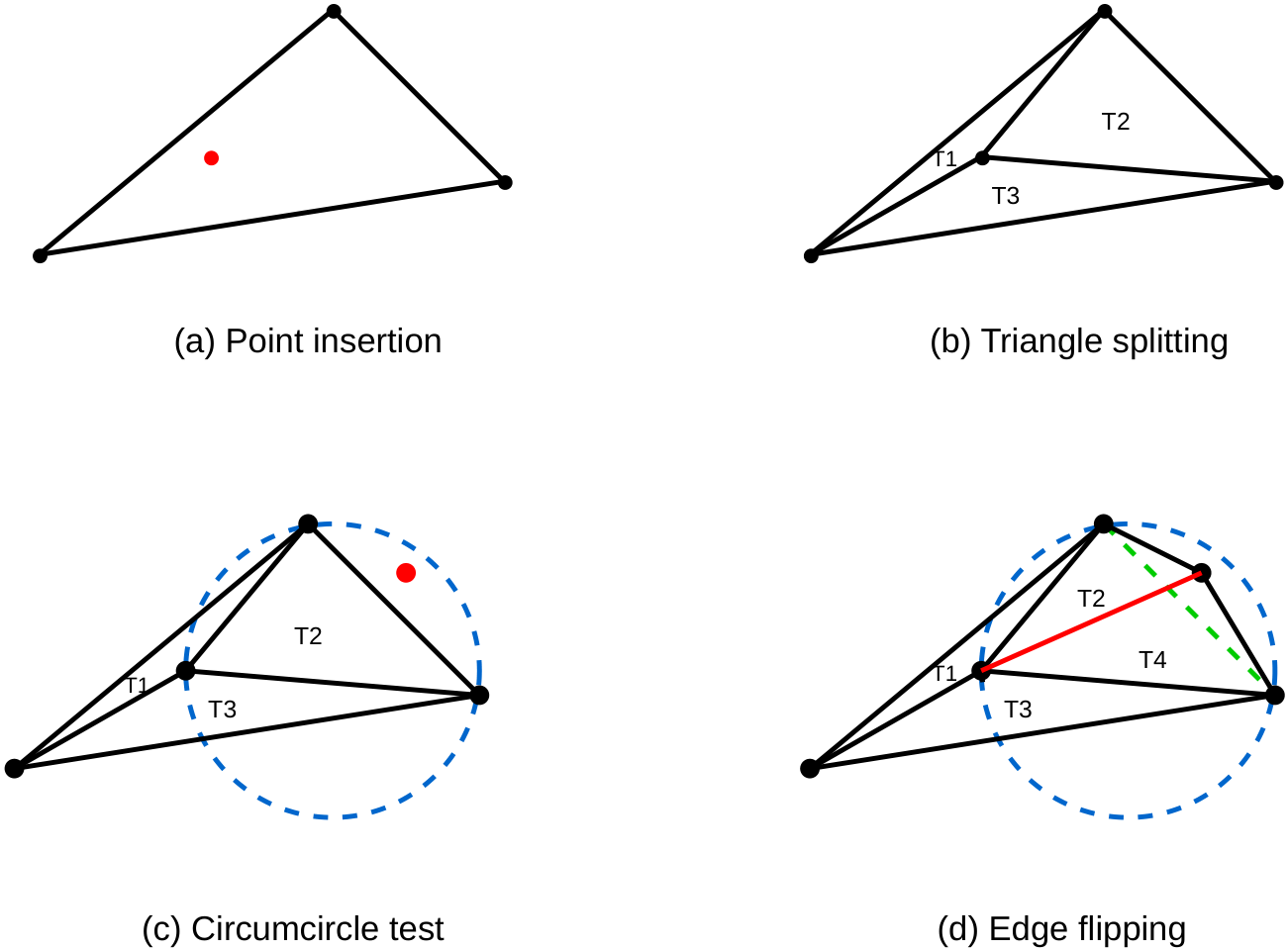
The triangulation is initialised using a super-triangle that covers the normalised input domain. For each inserted point, the kernel first locates the containing triangle. The located triangle is then split into three new triangles by connecting the inserted point to the three vertices of the original triangle. Since this local update may violate the Delaunay condition, neighbouring edges are checked and legalised through edge flips. This procedure follows the classical incremental Delaunay triangulation and edge-legalisation principles [
5,
6,
16,
17].
Figure 1 illustrates the local insertion and edge-flip process used during incremental triangulation.
2.2. Hardware-Oriented Topology Representation
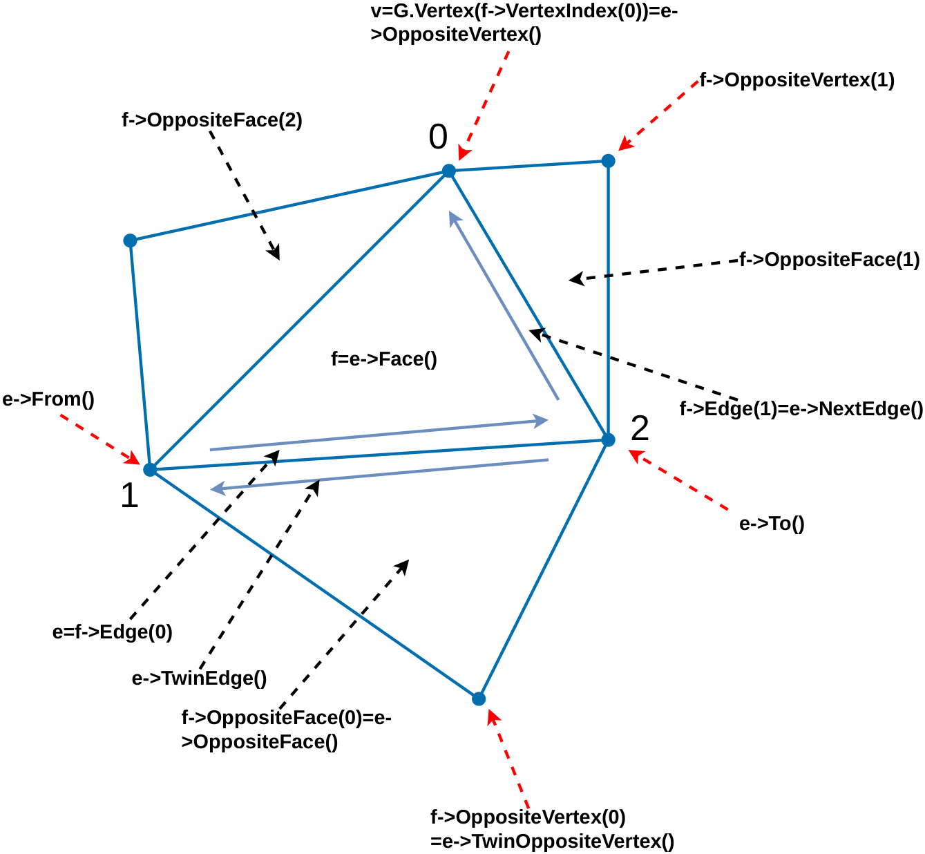
The triangulation topology is represented using a hardware-oriented half-edge structure derived from the DCEL concept [
11,
18]. Vertices, half-edges, and faces are stored in statically allocated arrays and referenced by fixed-width indices rather than software pointers. This representation allows the maximum storage footprint to be determined at synthesis time and avoids runtime heap allocation.
For the acceleration-oriented implementation, the half-edge connectivity is represented using explicit topological fields:
where
tail denotes the origin vertex,
twin denotes the opposite half-edge,
next and
prev denote the adjacent half-edges in the face cycle, and
face denotes the incident face. Each face also stores an anchor half-edge for local traversal.
Figure 2 illustrates the half-edge connectivity used for triangular mesh topology maintenance.
For the scalability-oriented implementation, the same local update semantics are preserved, but the topology is stored using a more compact triangle-centric half-edge encoding. Since each face is a triangle, its three half-edges follow a fixed local ordering. For face f, the three half-edges are indexed as , , and . Therefore, some local next and prev relations can be derived from the base half-edge index and local position instead of being stored explicitly. This reduces explicit topology storage while still supporting point insertion, edge flipping, and local face updates.
Both implementations use preallocated face and half-edge pools. When a face becomes inactive during retriangulation or edge flipping, its index is returned to a free list and can be reused by later insertions. This index-reuse mechanism bounds the memory footprint and provides predictable storage behaviour during repeated topology updates.
2.3. SoA Memory Layout and Storage Binding
The topology and geometry fields are implemented using a structure-of-arrays (SoA) layout [
19]. Instead of grouping all attributes into a single structure, each field is stored in an independent array. Representative arrays include vertex-coordinate arrays, face-validity arrays, face-vertex arrays, cached face-coordinate arrays, and half-edge connectivity arrays.
This SoA layout exposes independent memory-access streams and enables field-level storage binding in HLS. Arrays are mapped to BRAM, URAM, or LUTRAM according to their depth, bit width, and access frequency [
20,
21,
22,
23,
24]. Large coordinate or cached geometry arrays are placed in URAM where appropriate. Frequently accessed connectivity fields are mapped to BRAM to provide efficient random access. Shallow metadata arrays and free-list structures are mapped to LUTRAM to reduce BRAM pressure.
The acceleration-oriented implementation keeps the main topology arrays and grid candidate lists on-chip to minimise memory access latency during point location and topology updates. The scalability-oriented implementation also keeps the main topology and geometry arrays on-chip but reduces the on-chip storage pressure of the grid index by placing the global grid candidate lists in external memory. Therefore, in both variants, the critical topology update path remains primarily on-chip.
Table 1 summarises the storage mapping of the main memory-consuming data structures in the 16,000-point scalability-oriented configuration, based on the HLS Bind Storage Report.
The remaining shallow metadata, free-list, and usage-status arrays are primarily mapped to LUTRAM, with only a small additional contribution to the overall on-chip memory usage. The complete HLS configuration uses 268 BRAM_18K blocks, equivalent to 134 36-Kb BRAM tiles, and 56 URAM blocks according to the top-level HLS storage report. The scalability-oriented implementation stores the global grid candidate buffers in external DDR, whereas the acceleration-oriented implementation retains these candidate lists in on-chip BRAM.
2.4. Hilbert-Ordered Grid-Assisted Point Location
Point location is performed using a uniform grid index combined with Hilbert-ordered insertion. Hilbert-based insertion orders have been used to improve spatial locality in incremental Delaunay construction [
12]. In this work, Hilbert index computation and point sorting are performed before the point stream is sent to the triangulation kernel. This keeps the kernel control path simple while improving the spatial locality of successive insertions.
To avoid overly concentrated insertion sequences, a strided Hilbert sampling strategy is applied after global Hilbert sorting. The points are first sorted according to their Hilbert indices and then reordered using an interleaved stride . This preserves local spatial ordering while distributing early insertions more broadly across the input domain.
The spatial domain is partitioned into a compile-time-configurable grid. In the evaluated configuration, . Each grid cell maintains a fixed-capacity list of candidate triangle indices. The grid dimension affects both the spatial selectivity of point location and the memory required by the grid index. Increasing M generally reduces the number of candidate triangles associated with each cell, thereby improving point-location selectivity, but also increases the number of grid cells and the corresponding candidate-list storage.
In the acceleration-oriented implementation, the complete grid candidate lists are stored in on-chip BRAM to provide low-latency access. In the scalability-oriented implementation, the same grid mapping and search logic are retained, but the global candidate lists are moved to external DDR. A small BRAM-resident cache stores the candidate data required by the current local search region, reducing repeated DDR accesses while allowing the grid structure to support the 16,000-point configuration.
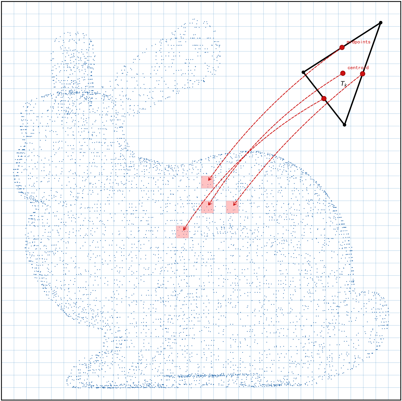
Uniform-grid-based point-location acceleration has been used in prior Delaunay triangulation algorithms to reduce the cost of locating containing triangles [
25]. During topology updates, each triangle is assigned to grid cells using its centroid and the midpoints of its three edges, as shown in
Figure 3. This mapping improves coverage near cell boundaries without requiring costly intersection tests between triangles and grid cells.
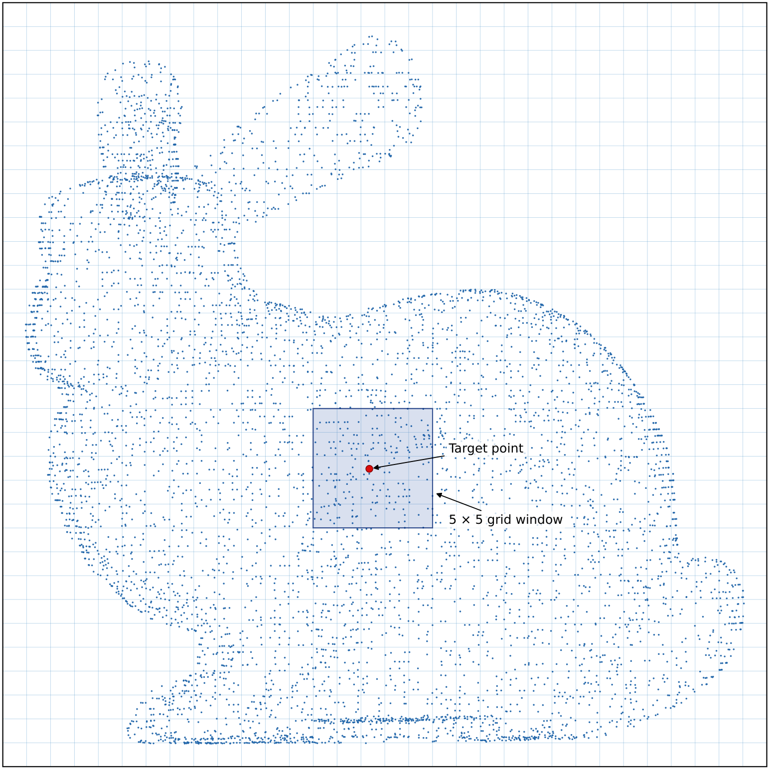
For a query point, the kernel first searches the grid cell containing the point and its neighbouring cells within a fixed
window. In this implementation,
, resulting in a
local search region. The resulting grid-assisted point location process is illustrated in
Figure 4. For the scalability-oriented implementation, the candidate entries associated with this local search region are first loaded from DDR into the on-chip cache before the containing-triangle tests are performed. If the local search does not find a valid containing triangle, a fallback search is executed to preserve correctness for boundary, non-local, or degenerate cases.
Because both the local window size and the per-cell candidate capacity are fixed at compile time, the local point-location path has a bounded candidate-checking budget. If each cell stores at most
candidate triangles, the maximum number of local candidate checks is bounded by
With
and
in the evaluated configuration, the local search checks at most
candidate entries. The fallback path is retained to ensure correctness when the containing triangle is not included in the local candidate lists.
The selected grid resolution therefore represents a trade-off between local-search selectivity and grid-storage demand. To investigate this trade-off, the effects of grid resolution and input size on the fallback rate are evaluated experimentally in
Section 3.5.
2.5. Architecture Variants
Two architecture variants are implemented within the same incremental triangulation framework.
The first variant is the acceleration-oriented architecture. In this version, the main topology arrays and grid candidate lists are kept in on-chip memory. External DDR traffic is mainly limited to streaming input points into the accelerator and streaming output triangle records back to the PS. Since both the point-location index and the topology update path are kept on chip, this variant is optimised for lower latency on small to medium point sets.
The second variant is the scalability-oriented architecture. This version is designed to support larger point sets while retaining the same incremental triangulation flow. The complete triangulation topology is not moved to DDR. Instead, the vertex arrays, face arrays, half-edge arrays, cached face-coordinate arrays, and local update structures remain statically allocated inside the PL and are mapped to BRAM, URAM, and LUTRAM. The main difference is that the global grid candidate lists are exposed as external memory buffers through AXI master interfaces. During point location, only the active grid neighbourhood is loaded into a small BRAM-resident local cache before candidate checking is performed. This DDR-assisted grid organisation reduces the on-chip memory pressure of the grid index and extends the supported input capacity.
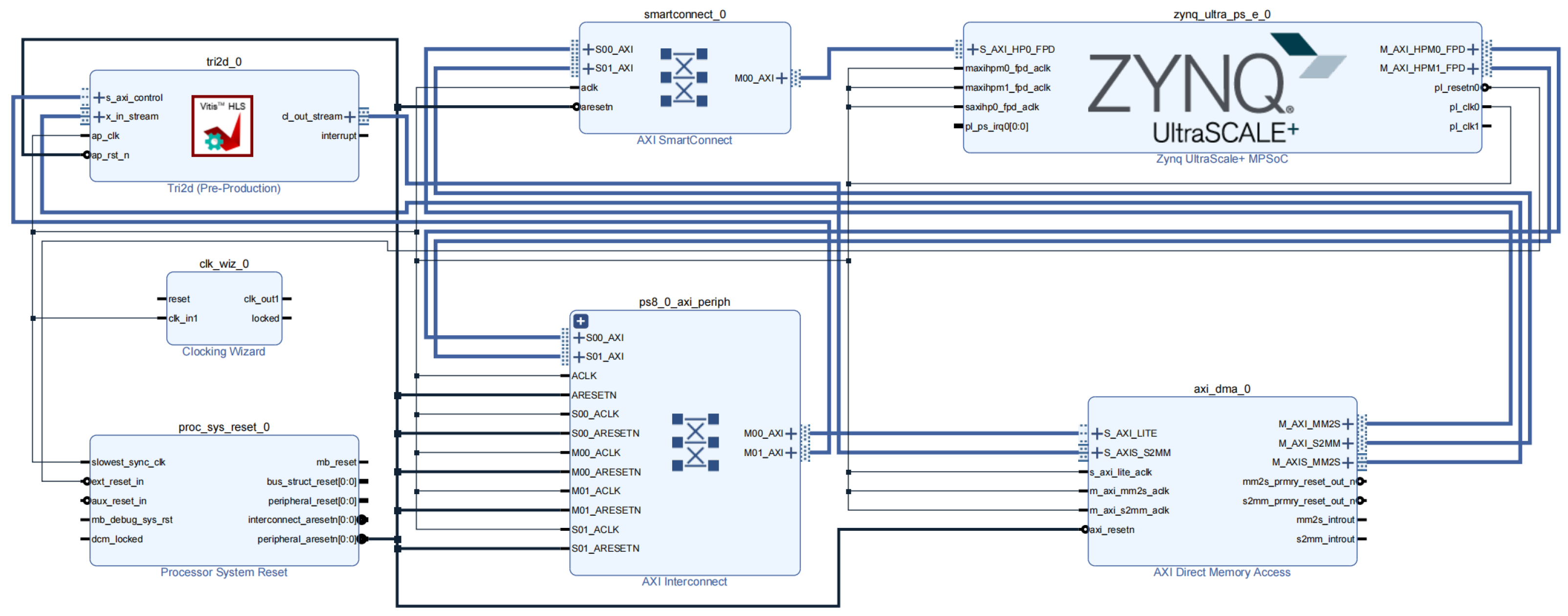
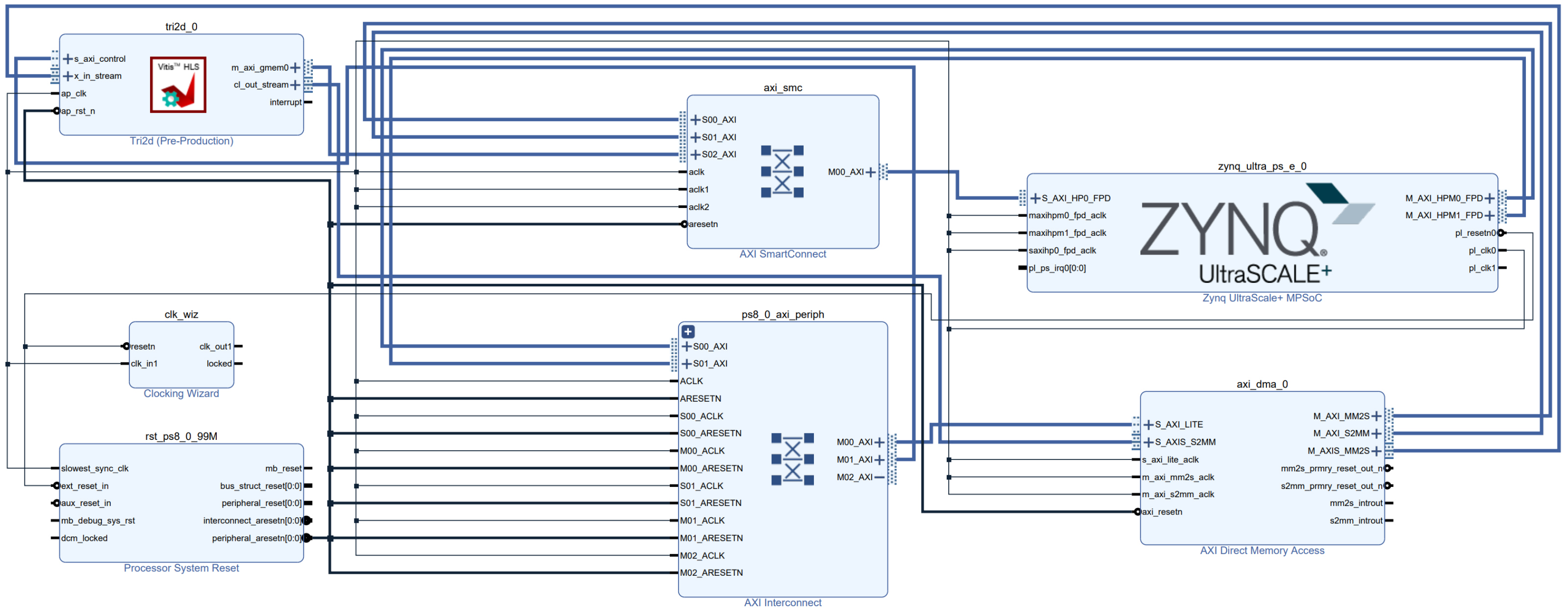
The PS/PL system integration of the two variants is shown in
Figure 5 and
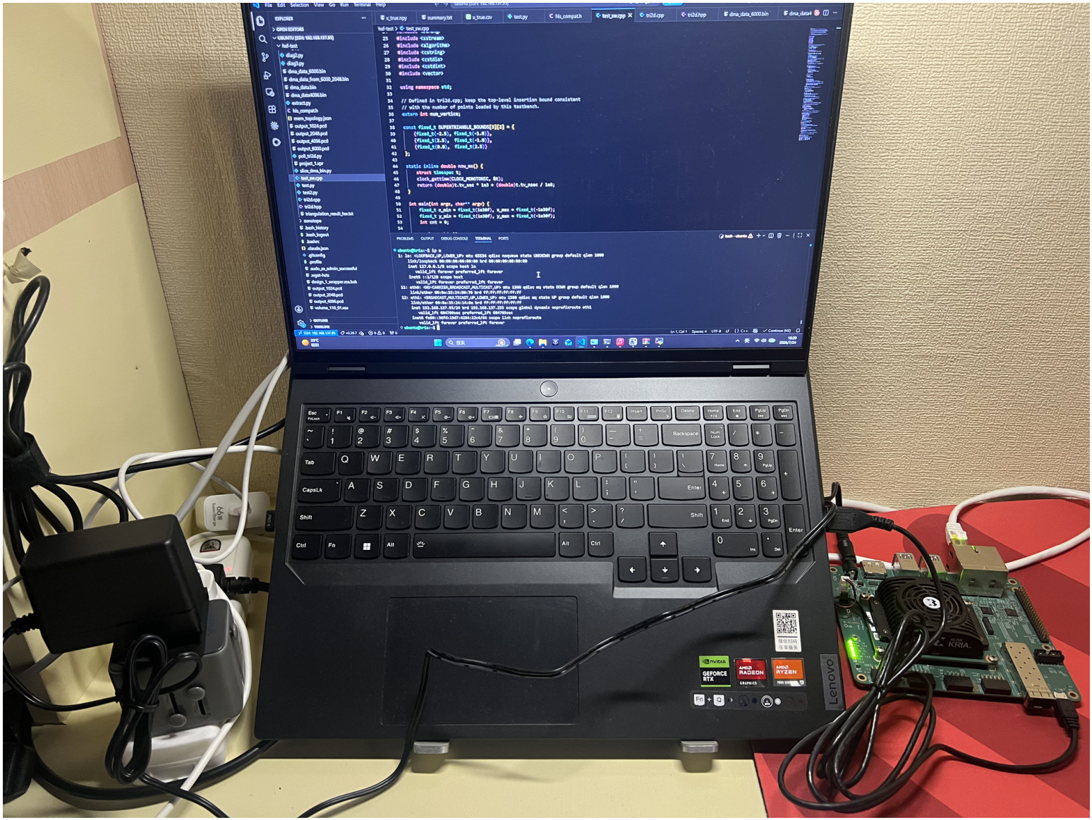
Figure 6, respectively. The same KR260 target platform is used for synthesis and implementation of both variants; the difference lies in the loaded accelerator architecture and the internal memory organisation. The physical experimental setup used for the on-board evaluation is shown in
Figure 7.
2.6. Implementation and Evaluation Setup
Both variants are implemented using AMD Vitis HLS [
20,
26] and integrated into the PS/PL architecture of the AMD Kria KR260 platform [
13]. Recent embedded FPGA accelerators for sparse visual odometry, LiDAR motion segmentation, and point-cloud registration also demonstrate the suitability of HLS-based SoC-FPGA platforms for streaming perception and point-cloud workloads [
15,
27,
28]. The triangulation core exposes an AXI4-Lite interface for control, AXI4-Stream ports for input and output data, and an interrupt signal for completion notification. For the scalability-oriented variant, the kernel additionally exposes AXI master interfaces for the DDR-assisted grid candidate buffers.
In the PS/PL deployment, the PS prepares input buffers in DDR, configures the DMA and the triangulation kernel through AXI4-Lite, and starts the streaming transfer. The MM2S DMA channel streams the ordered point records into the accelerator, and the S2MM channel writes the generated triangle records back to DDR. After execution, the PS collects the output triangle list and removes triangles incident to the super-triangle vertices.
The target application context is point-cloud triangulation for indoor navigation and mapping. Prior studies on LiDAR-aided UAV navigation, embedded indoor navigation, and Delaunay-based spatial modelling show that triangulated point sets can provide useful geometric representations for navigation and reconstruction tasks [
29,
30,
31,
32]. This work also extends the line of FPGA-based algorithmic acceleration established in prior work [
10].
Functional correctness is verified using C simulation, C/RTL co-simulation, and output validation of the generated triangulation results. Unless otherwise stated, both HLS designs target a 100 MHz operating frequency, and the reported FPGA resource utilisation is obtained from the KR260 synthesis and implementation reports.
The deployed PS–PL runtime is measured directly on the KR260. During this experiment, the Delaunay triangulation is executed in the PL, while the PS performs accelerator configuration, DMA control, completion polling, and runtime measurement. The reported end-to-end runtime includes DMA setup, accelerator execution, and completion of the input and output DMA transfers. For each input size, one warm-up run is performed and excluded from the analysis, followed by 20 timed runs. The arithmetic mean and standard deviation are reported.
A separate CPU-only implementation of the same incremental triangulation flow is executed entirely on the ARM Cortex-A53 processor of the KR260. This implementation uses the same input ordering, point-location procedure, topology-update flow, and output filtering, and therefore provides a same-platform embedded software baseline. Each input size is evaluated over 29 timed runs, and the arithmetic mean and standard deviation are reported.
The same-flow Vitis C-simulation results obtained on a PC workstation equipped with an Intel Core Ultra 7 265K processor are retained as an additional reference. These results follow the data organisation and algorithmic flow of the corresponding HLS designs, but they are reported separately from the Cortex-A53 embedded software baseline. Accordingly, the speedup over the Cortex-A53 implementation represents the embedded software-to-hardware comparison, whereas the speedup over the workstation Vitis C-simulation result represents the original same-flow HLS reference comparison.
The evaluation uses 1024-, 2048-, 4096-, and 6000-point inputs for scaling, embedded-baseline comparison, and parameter ablation. The 6000-point input is also used for direct comparison between the two architecture variants, while the 16,000-point input is used to evaluate the extended capacity of the scalability-oriented implementation. The reported metrics include runtime, speedup, statistical variability, correctness, numerical precision, fallback rate, grid-resolution sensitivity, supported capacity, power, and FPGA resource utilisation.
3. Results
3.1. Dataset and Evaluation Protocol
The proposed framework is evaluated using representative two-dimensional point sets derived from the Stanford Bunny point cloud model. The original three-dimensional point cloud is projected onto the plane to form two-dimensional inputs for triangulation. Two primary operating points are considered. The 6000-point dataset is used for direct comparison between the acceleration-oriented and scalability-oriented variants under the same input size, while the 16,000-point dataset is used to evaluate the extended capacity of the scalability-oriented variant. Additional input sizes of 1024, 2048, and 4096 points are used in the scaling and embedded software baseline experiments.
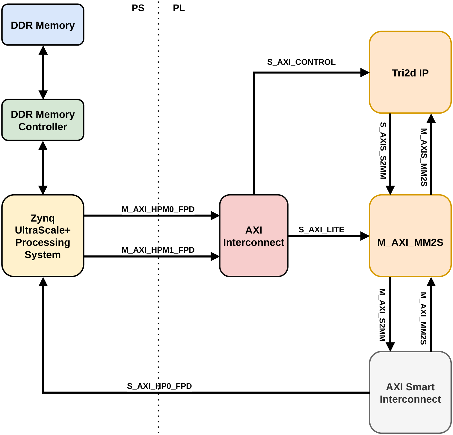
Figure 8 shows the PS/PL dataflow used in the experimental platform. The PS configures the accelerator through AXI4-Lite, while input and output streams are transferred between DDR memory and the triangulation accelerator through AXI DMA.
In the deployed configuration, the Delaunay triangulation is executed entirely by the accelerator in the PL. The ARM Cortex-A53 processor in the PS acts only as the embedded host: it loads the input data, configures and launches the accelerator, manages the AXI DMA transfers, polls for completion, and records the end-to-end runtime. This is the intended deployment mode of the proposed accelerator in an embedded edge-computing system.
Input points are normalised to the dataset bounding box before triangulation. Hilbert indices are computed on the host side with
HILBERT_ORDER = 8 when Hilbert ordering is enabled. The FPGA-side spatial index uses a default
grid, a fixed
local search window, and a default per-cell candidate capacity of
, unless otherwise stated. The sensitivity of the fallback rate to grid resolution and input size is evaluated separately in
Section 3.5. All hardware implementations target a 100 MHz clock.
The performance of the deployed PS–PL system is measured on the KR260 platform. For the acceleration-oriented scaling experiment, one warm-up run is performed and excluded from the analysis, followed by 20 timed runs. The reported end-to-end runtime includes accelerator configuration, DMA setup and transfer, accelerator execution, completion polling, and output transfer. The arithmetic mean and standard deviation are reported. RTL co-simulation is also used to report cycle-level kernel latency at 100 MHz and to verify the generated RTL.
A separate CPU-only implementation of the same incremental triangulation flow is executed on the ARM Cortex-A53 processor of the KR260 to provide an embedded software baseline. In this configuration, the complete triangulation is performed in software on the PS rather than by the PL accelerator. Each input size is measured over 29 timed runs, and the arithmetic mean and standard deviation are reported.
The original same-flow Vitis C-simulation results obtained on a PC workstation equipped with an Intel Core Ultra 7 265K processor are retained as an additional reference. This reference follows the same incremental triangulation flow and data organisation as the corresponding HLS design. Accordingly, speedups over the Cortex-A53 embedded-software baseline and the workstation Vitis C-simulation reference are reported separately. The former is the same-platform embedded-software-to-hardware comparison, while the latter preserves the original same-flow HLS comparison.
3.2. Correctness Validation
Before evaluating performance, the triangulation output is validated against the Triangle reference implementation by Shewchuk [
3]. Triangle is used only as a correctness reference in this work, not as the performance baseline, because the objective is to evaluate the hardware mapping of the proposed incremental flow.
For each test case, the same input point set is processed by the proposed accelerator and the Triangle reference. The outputs are compared using three metrics: triangle count agreement, Delaunay satisfaction rate based on the empty circle test, and Jaccard-style triangle set agreement. These metrics evaluate both the geometric validity of the generated triangulation and its consistency with the reference implementation.
Table 2 reports the correctness results on the 16,000-point dataset. The accelerator produces 31,909 valid triangles, compared with 31,936 triangles generated by Triangle, giving a triangle count agreement of 99.92%. The empty circle test reports a Delaunay satisfaction rate of 99.17%, and the triangle set agreement with the reference is 98.26%. These results indicate that the generated triangulation closely matches the reference output, with the remaining differences limited to a small fraction of local configurations.
The implementation uses separate fixed-point types for coordinate storage, intermediate geometric calculations, and evaluation of the in-circle determinant. Additional precision-sensitivity experiments were therefore performed to identify the main source of the remaining numerical disagreement.
For the acceleration-oriented implementation, which supports up to 6000 points without DDR-assisted grid storage, the coordinate-storage precision was varied while the remaining arithmetic configuration was kept unchanged. The results are summarised in
Table 3.
The 16-bit configuration introduces noticeable coordinate quantisation error. However, increasing the coordinate width from 20 to 32 bits produces only minor changes in the three correctness metrics. Therefore, ap_fixed<24,4> is retained for the acceleration-oriented implementation. Since the correctness metrics change only marginally when the coordinate width is increased beyond 20 bits, the use of ap_fixed<24,4> does not materially affect the conclusions of the subsequent experiments.
For the 16,000-point scalability-oriented implementation, the additional experiments show that the main numerical limitation is not the
ap_fixed<24,4> coordinate-storage type but the width of the intermediate in-circle determinant. In this experiment,
fixed_t and
fixed_calc_t were fixed at
ap_fixed<24,4> and
ap_fixed<33,6>, respectively, while the determinant width was varied. The corresponding results are summarised in
Table 4.
Increasing the determinant width from 50 to 54 bits reduces the empty-circle violation rate from 3.01% to 0.83%, while the triangle count agreement remains unchanged at 99.92%. This confirms that the previously observed correctness loss at 16,000 points was primarily caused by insufficient width in the determinant intermediate result rather than by the coordinate-storage precision alone. As the point set becomes denser, more local configurations produce determinant values close to zero, making the sign of the in-circle predicate more sensitive to fixed-point truncation. The final scalability-oriented implementation therefore uses ap_fixed<54,10> for fixed_det_t.
The wider determinant type affects temporary arithmetic values rather than the large topology and coordinate arrays. The corresponding HLS synthesis and simulation results show no material change in BRAM or URAM utilisation or in the reported execution latency. The correctness improvement is therefore obtained without a significant effect on the memory footprint or performance of the implementation.
An empty-circle violation may locally alter edge connectivity and reduce mesh quality. Such differences can affect downstream applications that rely on strict Delaunay properties, including quality-sensitive interpolation, finite-element mesh generation, and topology-dependent geometric queries. For the point-cloud preprocessing application considered in this work, the 99.92% triangle count agreement and 98.26% triangle set agreement indicate that the remaining differences are localised. Nevertheless, when a strict Delaunay guarantee is required, a wider determinant data path or adaptive higher-precision evaluation for near-zero determinant values should be used.
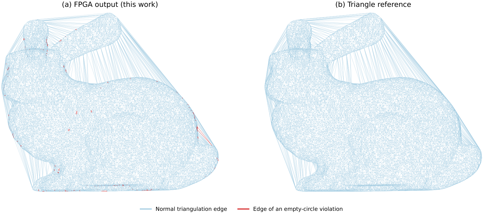
Figure 9 presents a visual comparison between the accelerator output and the Triangle reference for the 16,000-point dataset. At the global scale shown, the two triangulations appear almost indistinguishable. This near-identical appearance reflects the close agreement between the two triangulations and is consistent with the high triangle-count agreement of 99.92% reported in
Table 2. The remaining differences, indicated by the Delaunay satisfaction rate of 99.17% and the triangle-set agreement of 98.26%, are confined to a small number of isolated, numerically sensitive local configurations and are therefore not visible at this global zoom level. Thus, the visual similarity does not imply that the two subfigures show the same image.
3.3. Acceleration-Oriented Variant
The acceleration-oriented variant is evaluated on the representative 6000-point dataset. This variant keeps the main topology arrays and grid candidate lists in on-chip memory and is therefore optimised for low-latency execution on moderate-sized point sets.
Table 5 reports the performance of the acceleration-oriented variant relative to the same-flow workstation Vitis C-simulation reference. The reference on the Intel Core Ultra 7 265K workstation requires 15,807 ms. In RTL co-simulation at 100 MHz, the accelerator completes the 6000-point triangulation in 482.25 ms, corresponding to a 32.7× speedup over this reference. The measured end-to-end PS–PL runtime on the KR260 is
ms, corresponding to a 50.0× speedup over the same workstation reference and a throughput of approximately 18,992 points/s.
For the same input, the CPU-only Cortex-A53 implementation requires ms. The deployed PS–PL system therefore achieves a 1.96× speedup over the embedded software baseline. The 50.0× and 1.96× values use different references and are reported separately.
The measured PS–PL end-to-end runtime is lower than the RTL co-simulation latency. This difference is attributed to the different measurement flows: RTL co-simulation provides a conservative cycle-level estimate of the generated RTL with simulation-side interface modelling, whereas the deployed PS–PL result is measured using the deployed bitstream under the actual KR260 execution environment. The two values are therefore used as complementary measurements. The PS–PL result demonstrates the practical low-latency behaviour of the fully on-chip acceleration-oriented variant at the 6000-point operating point.
The hardware feasibility of this variant is confirmed by the Vivado synthesis and implementation flow on the KR260.
Table 6 reports the post-implementation resource utilisation. The design meets the 100 MHz timing target, with WNS = 0.01 ns and WHS = 0.010 ns.
Table 7 reports the corresponding power estimate.
The utilisation profile indicates that the design is primarily memory-dominant rather than compute-dominant. BRAM and LUTRAM utilisation are considerably higher than DSP and register utilisation, which motivates the scalability-oriented variant that reduces the on-chip storage pressure of the grid index.
3.4. Scalability-Oriented Variant and Design Trade-Off
The scalability-oriented variant is evaluated to show how the proposed framework trades latency for supported input capacity. On the same 6000-point dataset, this variant completes the triangulation in 868.51 ms in RTL co-simulation at 100 MHz, corresponding to a 9.7× speedup over its same-flow workstation Vitis C-simulation reference of 8392 ms, as shown in
Table 8. Compared with the acceleration-oriented variant, the scalability-oriented variant has higher latency at the same input size. This is expected because it is designed to reduce on-chip grid-index storage pressure and support larger inputs, rather than maximise peak acceleration for moderate-sized point sets.
Post-implementation analysis confirms that the scalability-oriented variant meets timing at 100 MHz on the KR260 for the 6000-point configuration. The post-implementation summary is given in
Table 9. The design achieves a positive WNS of 0.129 ns with zero failing endpoints, and the estimated total on-chip power is 2.942 W.
Because the two variants use different memory organisations, their same-flow workstation Vitis C-simulation references are also different. The acceleration-oriented reference follows the fully on-chip grid organisation, whereas the scalability-oriented reference follows the SoA-based topology layout and DDR-assisted grid organisation used by the corresponding hardware variant. Each speedup relative to a Vitis C-simulation reference therefore measures the benefit of mapping that specific design flow to FPGA hardware. These values are reported separately from the Cortex-A53 comparison and should not be interpreted as embedded ARM-to-FPGA speedups.
Table 10 summarises the trade-off between the two design points. The acceleration-oriented variant achieves lower latency by keeping the grid candidate lists on-chip, which is effective for the 6000-point operating point. The scalability-oriented variant relocates the global grid candidate lists to external memory while retaining a BRAM-resident local neighbourhood cache, thereby extending the supported capacity to 16,000 points at the cost of higher latency.
It should be noted that
Table 10 contains two types of comparison. The 6000-point RTL latency and fallback-rate rows compare the two variants under the same input size. In contrast, the representative PS–PL runtime and throughput rows report each variant at its intended operating point: 6000 points for the acceleration-oriented variant and 16,000 points for the scalability-oriented variant.
The 16,000-point dataset is used to further evaluate the capacity of the scalability-oriented variant. This input size is beyond the practical on-chip memory budget of the acceleration-oriented configuration.
Table 11 reports the corresponding performance. In RTL co-simulation, the DDR-assisted scalability-oriented variant completes the triangulation in 4360.6 ms, producing 31,909 valid triangles and achieving a 19.0× speedup over the same-flow workstation Vitis C-simulation reference of 82,958 ms. On the KR260 board, the measured median PS–PL runtime is 8877.790 ms, corresponding to a 9.3× speedup over the same workstation Vitis C-simulation reference.
The gap between RTL co-simulation and deployed PS–PL execution is more pronounced for the scalability-oriented variant because its design objective of supporting larger point sets requires off-chip grid access. The PS–PL measurement includes the practical effects of DDR access, AXI/DMA synchronisation, PS/PL interaction, and memory arbitration, whereas RTL co-simulation mainly reflects the cycle-level behaviour of the synthesised kernel.
The implementation results for the 16,000-point configuration are reported in
Table 12. The design fits within the available resources of the KR260 device, but BRAM and URAM utilisation reach 94.44% and 87.50%, respectively. These high utilisation values indicate that the 16,000-point configuration is close to the practical capacity ceiling of the proposed design on the KR260. The achieved clock period is 8.971 ns, meeting the 100 MHz target.
To further identify the source of the super-linear latency increase, the HLS module-level latency report is used to decompose the main point-insertion loop.
Table 13 reports the static latency estimates for the principal stages of one point insertion in the scalability-oriented implementation.
The HLS stage-level report indicates that the point-insertion and update stage accounts for approximately 96.18% of the estimated per-point latency, whereas point location accounts for 3.82%. Within the insertion stage, FINAL_UPDATE is the dominant component, accounting for approximately 94.75% of the complete insertion latency. In comparison, the static latency attributed to edge legalisation is small. Within the point-location stage, the fallback search path requires 42,006 cycles, corresponding to approximately 82.7% of the worst-case point-location latency.
The HLS report gives the same worst-case per-iteration latency of 1,331,788 cycles for the 6000- and 16,000-point configurations. Consequently, the static estimate for the complete INSERT_POINTS loop increases from approximately 7.991 billion cycles at 6000 points to 21.309 billion cycles at 16,000 points, which is proportional to the 2.67× increase in the loop trip count. In contrast, the aggregate latency of the remaining initialisation, input reading, grid setup, and output collection stages increases only from approximately 0.356 million cycles to 0.386 million cycles. These stages therefore do not constitute the main scalability bottleneck.
The RTL co-simulation latency increases from 868.51 ms at 6000 points to 4360.6 ms at 16,000 points, corresponding to an increase of approximately 5.02×. This is substantially higher than the 2.67× growth predicted by the static loop-trip estimate. The difference indicates that the additional scaling overhead arises inside the data-dependent point-insertion loop. The fallback rate increases from 2.9% to approximately 5.1%, and the larger input also produces a larger active-triangle pool. Consequently, fallback scans, topology and grid updates, and DDR accesses incur additional execution and memory-stall costs that are not represented by the fixed per-iteration HLS estimate.
The profiling results therefore identify the point-insertion and update path, particularly the FINAL_UPDATE stage, as the dominant static latency component. They also show that the observed super-linear scaling is not caused by initialisation or output collection but by data-dependent operations and external-memory behaviour within the main insertion loop.
Overall, the two variants occupy distinct design points within the same framework. The acceleration-oriented variant is preferable when latency reduction on moderate-sized point sets is the primary objective, while the scalability-oriented variant is preferable when larger supported workloads and reduced on-chip grid storage pressure are required.
3.5. Scaling and Ablation Analysis
Additional scaling and ablation studies are performed on the acceleration-oriented variant. The scaling study reports results for the workstation Vitis C-simulation reference, the Cortex-A53 embedded software baseline, RTL co -simulation, and the KR260 PS–PL implementation. The grid-resolution study evaluates the sensitivity of the fallback rate to the spatial-index configuration, whereas the Hilbert-ordering and per-cell-capacity ablations are evaluated using RTL co-simulation at 100 MHz to isolate the effect of each algorithmic parameter.
For each input size, the KR260 PS–PL experiment was preceded by one warm-up run, which was excluded from the results, and was then repeated 20 times. The measured PS–PL end-to-end runtime includes accelerator configuration, DMA setup and transfer, accelerator execution, completion polling, and output transfer. The arithmetic mean and standard deviation are reported to quantify runtime and run-to-run measurement variability. The Cortex-A53 CPU-only implementation was measured over 29 timed runs for each input size.
Table 14 reports the scaling behaviour of the acceleration-oriented variant. The same-flow Vitis C-simulation reference is obtained on the Intel Core Ultra 7 265K workstation, while the end-to-end PS–PL runtime is measured on the KR260 platform. The speedup in this table is calculated using the mean PS–PL runtime and is explicitly relative to the workstation Vitis C-simulation reference.
The standard deviations of the PS–PL measurements range from 0.042 to 0.074 ms, while the coefficients of variation range from 0.013% to 0.123% across the four input sizes. These results indicate low run-to-run variability and good repeatability of the end-to-end PS–PL measurements.
Table 15 compares the CPU-only Cortex-A53 software baseline with the deployed PS–PL system on the same KR260 platform. In the PS–PL configuration, the Delaunay triangulation is executed by the accelerator in the PL, while the PS performs only host-side control, DMA transfers, and timing. In the Cortex-A53 baseline, the complete triangulation flow is executed in software on the PS.
At 1024 points, the fixed host-control and DMA-transfer overheads are not fully amortised, and the CPU-only Cortex-A53 implementation is faster. The two configurations provide similar performance at 2048 points. As the input size increases, the benefit of executing the triangulation in the PL becomes more pronounced, yielding PS–PL speedups of 1.60× at 4096 points and 1.96× at 6000 points. Thus, the same-platform embedded comparison complements the separately reported speedups over the workstation Vitis C-simulation reference.
The influence of grid resolution is evaluated using two complementary experiments. First, the same 6000-point dataset is processed using different grid resolutions to examine the trade-off between local search selectivity and grid storage demand. Second, the grid resolution is fixed at , while the input size is varied from 1024 to 6000 points to evaluate the stability of the selected configuration. Hilbert ordering is enabled and in all cases.
For the fixed 6000-point dataset, increasing the grid resolution from
to
reduces the fallback rate from 39.0% to 12.6%. However, further increasing the resolution to
and
reduces the fallback rate only slightly, to 12.0% and 11.8%, respectively. Since every grid cell maintains a fixed-capacity candidate list, the grid index storage increases proportionally to
. A
grid therefore contains 56.25% more cells than a
grid, while reducing the fallback rate by only 0.8 percentage points. This diminishing return motivates the selection of
as the default configuration. The corresponding results are summarised in
Table 16.
With the grid resolution fixed at , the fallback rate remains between 11.6% and 16.0% for input sizes from 1024 to 6000 points and does not increase monotonically with the number of input points. The selected grid resolution therefore maintains stable point-location selectivity across the evaluated operating range of the acceleration-oriented variant. For substantially larger or highly non-uniform point sets, dynamically adapting the grid resolution or using a hierarchical grid remains a direction for future work.
The effect of Hilbert ordering is shown in
Table 17. At
, Hilbert ordering reduces the fallback rate from 14.7% to 12.6% and decreases RTL co-simulation latency from 513.77 ms to 482.25 ms. This improvement is obtained without adding FPGA-side Hilbert computation, since point ordering is performed before the stream enters the accelerator.
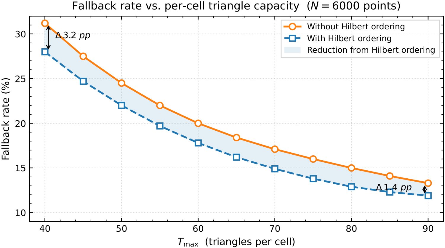
Table 18 and
Figure 10 show the sensitivity to the per-cell triangle capacity
. Increasing
reduces fallback events monotonically. Hilbert ordering consistently lowers the fallback rate across all tested capacities, although its relative benefit becomes smaller when the candidate capacity is already large.
At the baseline setting of , the fallback rate is reduced to 12.6% with Hilbert ordering, providing a balanced trade-off between bounded memory usage and local search effectiveness. Since fallback searches may scan a much larger active triangle pool, the reduction in fallback rate contributes directly to lower latency without consuming additional FPGA resources.
4. Conclusions
This paper presented a memory-centric SoC-FPGA framework for incremental 2D Delaunay triangulation. By combining a hardware-oriented half-edge topology representation, a structure-of-arrays memory layout, platform-aware storage binding, and grid-assisted point location with a bounded local search path, the proposed framework maps irregular incremental triangulation to FPGA hardware with predictable memory usage.
Two implementation variants were developed within this shared architectural backbone. The acceleration-oriented variant targets low-latency execution by keeping the grid candidate lists and topology data structures on-chip. On the 6000-point workload, it achieves 482.25 ms in RTL co-simulation and ms in the deployed PS–PL system. These results correspond to a 32.7× speedup over the same-flow workstation Vitis C-simulation reference in RTL co-simulation, a 50.0× speedup for the deployed PS–PL system over the same reference, and a 1.96× speedup over the CPU-only Cortex-A53 implementation on the same KR260 platform.
The scalability-oriented variant extends the supported workload size using a DDR-assisted grid organisation. It supports the 16,000-point dataset on the same KR260 platform, achieving 4360.6 ms in RTL co-simulation and a median PS–PL runtime of 8877.790 ms. These correspond to speedups of 19.0× and 9.3×, respectively, over the same-flow workstation Vitis C-simulation reference.
Correctness validation against the Triangle reference implementation shows that the 16,000-point accelerator output contains 31,909 triangles, compared with 31,936 triangles in the reference output. The resulting triangle-count agreement, Delaunay satisfaction rate, and triangle-set agreement are 99.92%, 99.17%, and 98.26%, respectively. The remaining differences are limited to a small number of numerically sensitive local configurations.
In addition to latency reduction and capacity extension, the proposed designs maintain low estimated on-chip power. The acceleration-oriented and scalability-oriented implementations each have an estimated on-chip power consumption of only a few watts, which is important for embedded SoC-FPGA deployment, where thermal and energy budgets are limited. Overall, the proposed framework demonstrates that FPGA-based incremental Delaunay triangulation can be adapted to different embedded deployment requirements through memory-organisation choices. The acceleration-oriented variant is suitable for low-latency processing of moderate-sized point sets, whereas the scalability-oriented variant extends the supported input capacity on the same SoC-FPGA platform. This provides a practical basis for low-power FPGA-based geometric preprocessing in resource-constrained point-cloud applications.