Abstract
Several strategies for navigation in unfamiliar environments have been explored, notably leveraging advanced sensors and control algorithms for obstacle recognition in autonomous vehicles. This study introduces a novel approach featuring a redesigned joystick equipped with stepper motors and linear drives, facilitating WiFi communication with a four-wheel omnidirectional electric vehicle. The system’s drive units integrated into the joystick and the encompassing control algorithms are thoroughly examined, including analysis of stick deflection measurement and inter-component communication within the joystick assembly. Unlike conventional setups in which the joystick is tilted by the operator, two independent linear drives are employed to generate ample tensile force, effectively “overpowering” the operator’s input. Running on a Raspberry Pi, the software utilizes Python programming to enable joystick tilt control and to transmit orientation and axis deflection data to an Arduino unit. A fundamental haptic effect is achieved by elevating the minimum pressure required to deflect the joystick rod. Test measurements encompass detection of obstacles along the primary directions perpendicular to the electric vehicle’s trajectory, determination of the maximum achievable speed, and evaluation of the joystick’s maximum operational range within an illuminated environment.
1. Introduction
The motion of four-wheeled electric vehicles can be controlled by distributing the driving and regenerative braking torques using a PID controller [1]. In a simple autonomous braking system for a four-wheel drive vehicle, a linear actuator activates the brake or a stepper motor attached to the master cylinder for quick operation when sufficient force is applied to completely depress the pedal. The regulation of acceleration performance at low speeds for actuated electric vehicles is solved by combining the advantages of the acceleration slip-based and maximum torque-based regulation methods [2]. Motion controllers separate control laws from specific actuator setups using virtual global control variables that act on road vehicles with steer-by-wire systems [3]. In [4], a vehicle speed estimator was proposed for a four-wheel-independently-actuated electric vehicle using a Global Positioning System and Beidou Navigation Positioning (GPS-BD) module and a low-cost Inertial Measurement Unit (IMU). The omnidirectional mobility requires active omni-wheels with barrel-shaped rollers arranged around its outer circumference, which is expected to be effective in suppressing vibration during vehicle movement [5,6].
1.1. Literature Background
Omni-wheeled transportation vehicles or mobile robot that can move to a target location in an arbitrary direction on the floor is important for ensuring that work can proceed quickly and effectively in a limited space. A unit able to move in an arbitrary direction using only one wheel was proposed in [7,8,9].
Finally, many case studies with omnidirectional wheeled mobile robotic vehicles based on LiDAR have been presented to solve the problem of autonomous navigation in narrow and cluttered environments with unknown and unidentified static and dynamic obstacles of any shape [10,11]. The trajectory tracking problem of an autonomous racing electrical vehicle using intelligent control was reported in [12,13,14]. Significant advances have been made in LiDAR SLAM, which can often provide more robust and simultaneous localization and mapping in indoor navigation systems using 3D spatial information directly captured by LiDAR point clouds, and have been employed in robots and automated guided vehicles for industrial applications [15]. The autonomous obstacle avoidance and trajectory planning control strategy with low computational complexity, high cost-effectiveness, closed-loop stability verification, and the ability to quickly plan a collision-free smooth trajectory curve has been used in the overall control system of autonomous mobile robots [16,17,18,19,20].
The resilient model predictive control (MPC) problem for adaptive cruise control (ACC) systems under sensor attack in autonomous vehicle control systems and intrusion detection mechanism was proposed for distinguishing abnormal data in [21]. In [22], a vehicular platoon control approach was proposed for maintaining the appropriate longitudinal distance from preceding vehicles and tested under Denial-of-Service (DoS) attack and external disturbances that increase service times in the communication network and cause additional transmission delays, which can increase the risk of rear-end collisions between vehicles in platoons and autonomous intelligent transportation scenarios.
1.2. Contributions
This study is presents a new analog joystick with stepper motors to control the driving movement of an electric vehicle equipped with Mecanum 4 omnidirectional holonomic wheels for the obstacle detection scenario proposed in [23,24]. The joystick is equipped with stepper motors, and uses a Raspberry Pi as the main controller for the electronic components and for connecting and communicating by WiFi. To control the stepper motor in the joystick, and Arduino controller is used to send signals such as positions and stopping or mtion of the joystick to the motors every 30 s. The analog digital converter can collect signals from force-flexible sensors located on the joystick and communicate with the Arduino board. The PLC receives information about the distance from obstacles, the force applied to the joystick, the movement of the joystick, and the calculated direction and speed of the vehicle. When the motors are activated and the joystick is in position, the vehicle is ready to move. If an obstacle is recognized, the joystick cannot move due to an internal function that does not allow the vehicle to move in front of an obstacle. Based on the conducted tests, the system can detect obstacles more effectively in the main directions. Haptic feedback and wireless control are the main advantages of the proposed system, allowing for bidirectional data transmission. Information on the movement commands and surroundings is sent to the controlled target, and the haptic effect is used to convey the information to the user. The operator’s sense of touch is affected by signaling specific states of the controlled object. The application of the haptic feedback control technique in the prototype system was developed at the Silesian University of Technology, Gliwice, Poland.
The rest of this paper is organized as follows: Section 2 introduces the electric vehicle and analog joystick system; Section 3 describes the joystick design and linear drive; the experiments and the results obtained by experimental tests are discussed in Section 4; finally, Section 5 closes the paper with our conclusions.
2. Description of the Joystick System and Electric Vehicle
This research involves and electrical vehicle equipped by Swedish omnidirectional wheels that communicates with the joystick by WiFi and has a battery managed by a PLC controller [23,24]. The LiDAR (RPLiDAR A1M8 360 Degree Laser Scanner) uses the Raspberry Pi 4 minicomputer to identify the space of obstacles and send data to the PLC via WiFi. The laser measurement system is used in places with no direct sunlight, and is based on triangulation using a 2D laser scanner developed by Slamtec. The device can scan and rotate 360° clockwise in the environment within a maximum range of distance of 12 m. The resulting 2D point cloud can be used for mapping, localization, and generating a contour map of individual objects or the vehicle’s surroundings. The operating frequency of the RPLiDAR A1M8-R6 is 5.5 Hz sampling 360 points per revolution. The RPLiDAR A1M8-R6 3D laser scanner uses the UART serial interface for communication. The LiDAR was selected for its low cost and simple and accurate scanning of environment. The Raspberry Pi 4 has 4 × 1.5 GHz, 4 GB RAM, WLAN, BT, built-in Bluetooth/Wi-Fi support, ARM Cortex-A72 Quad Core CPU with 1.5 GHz, 2× microHDMI, 40 GPIO (General Purpose Input Output) pins, and audio and composite video output. In this system, the joystick is not tilted by operator but by two independent drives. The basic haptic feedback effect is involved in controlling the electric vehicle, and information received by force sensors and limit switches is inserted in the analog joystick for obstacle detection. In particular, the increase in the minimum value of the pressure force applied to the joystick rod allows it to be deflected as the vehicle approaches the obstacle. The resistance of the joystick changes depending on the distance between the vehicle and the obstacle. The minimum force is read by FSR force sensors mounted on the joystick and compared with the vehicle’s spatial response collision. A second Raspberry Pi 4 minicomputer plays the role of controller in the joystick component, determining the deflection of the joystick in the direction of the force applied by the user or towards the zero position of the joystick. The direction and speed of the vehicle are depend directly on the angle joystick deflection. A noticeable disadvantage of the implemented system is the low level of force generated by the drivers; these consist of two high-speed DC motors with a worm gear, with the rotational motion converted into linear motion through a belt-toothed transmission. This low amount of pull prevents the joystick from returning to the zero position when the operator applies more force, but is not enough to steer the vehicle. To prevent this situation, additional haptic effects are introduced in the form of stick vibrations. The intensity and frequency of vibrations reports the response of the vehicle to the surroundings. Despite the clearly haptic effect, the stick is unable to return to the zero position. The second disadvantage of previous solutions involves reading the current tilt position of the stick. The ultrasonic sensors mounted under the joystick socket read the distance to the element connecting the toothed belt with the rod pulley and calculate the resulting deflection of the stick. This measurement is subject to the presence of noise, which introduces instability in the operation of the joystick. To eliminate this noise, it is necessary to replace the linear drives used to tilt the joystick while providing accurate information about the inclination.
Linear Drives and Stepper Motor
The aim of this work is to introduce linear drives with stepper motors into the joystick system operating as the haptic feedback control. A linear drive is a set of elements, i.e., motor, controller, power supply, and mechanical components, that transfers energy and motion from the engine to the working machines and devices. In addition, the assemblies of mechanical devices convert the rotational motion of the engines into progressive movement or straight-line motion. The stepper motor is powered by electrical current pulses. The angle of rotation of the roller and its angular speed are directly proportional to the number and frequency of sending control pulses. The main advantage of using stepper motors is that it becomes possible to control the position in an open feedback loop. The linear drives ensure appropriate movement of the rod joystick by setting the accuracy and force. The linear drives are responsible for tilting the stick, and should be characterized by greater force while maintaining similar linear displacement and speed. The specific linear drive model selected for incorporation into the joystick frame consisted of aluminum and wooden plywood boards, with the assembly elements made of plastic and produced by 3D printing. New drive units are used in the joystick and control algorithms of the entire system, and the stick deflection and communication between individual joystick components were measured and analyzed.
3. Linear Drive Parameters and Control Elements
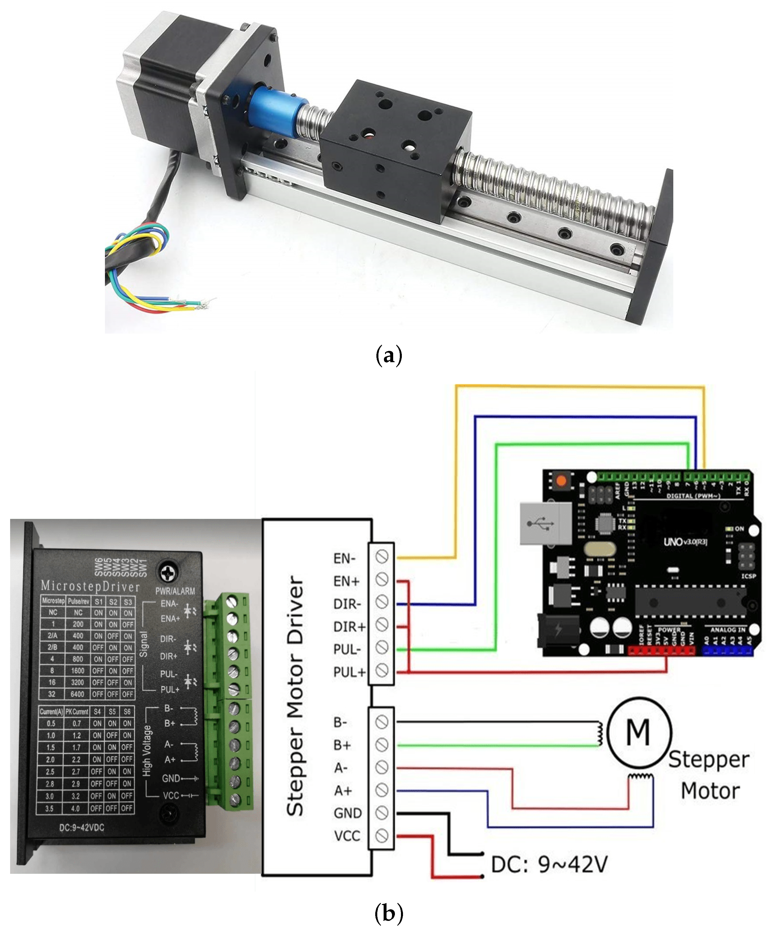
In the first stage, the parameters of the linear drives such as the speed and self-locking were selected based on the stroke or stroke length, which refers to how far the linear actuator moves and is equal to the fully extended length minus the fully retracted length. For the linear drive implemented on the joystick, the force pressure applied on it is an essential parameter for controlling the position within the linear unit. The position and the stick deflection angle are detected by ultrasonic sensors. The linear drive with a stepper motor mounted in the joystick is able to read the position directly at the control engine, assuming that there is no loss of steps. A linear drive with a ball screw gear driven by a stepper motor with a feed speed of 50 mm/s was selected. The ball screw gear is characterized by its resistance to movement, and was able to remain independent of the stick in the zero position despite the application of force by the operator during testing, as shown in Figure 1a.
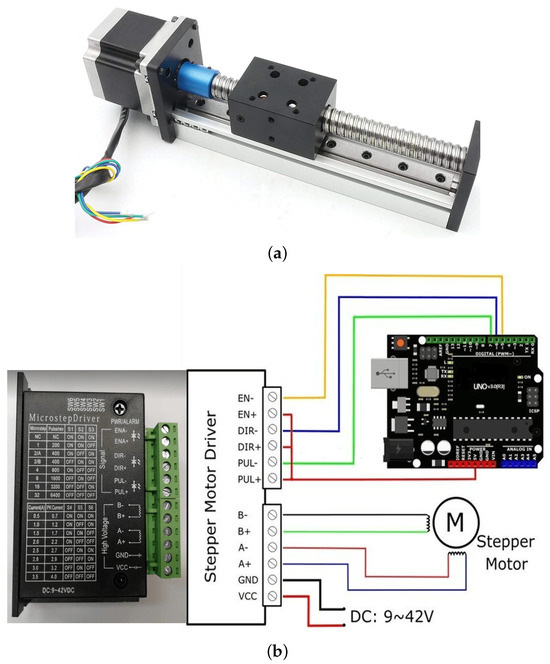
Figure 1.
(a) Ball screw gear and (b) HY-DIV268N-3A stepper motor controller, showing the connection diagram of the controller with stepper motor and control unit.
Before implementing the selected drives in the joystick, the control elements were selected and drive startup tests were carried out to check the capabilities of the motors (Figure 1a). For the control in the joystick, the Stepper Motor Driver HY-DIV268N-3A 12-40V 3A was selected as the controller operating in microstep control mode and supplied by the voltage available in the joystick, which was 12 V with a maximum operating current equal to 3 A (Figure 1b). The microstep control resolution and power supply current of the controlled motor are set by switches SW1 ÷ SW6 in the configuration of the controller housing. The EN signal is responsible for activating the motor, the DIR signal is set for the direction of motor rotation, and the PUL signal is responsible for the pulses that control of the motor movement, as shown in Figure 1b.
3.1. Joystick Design
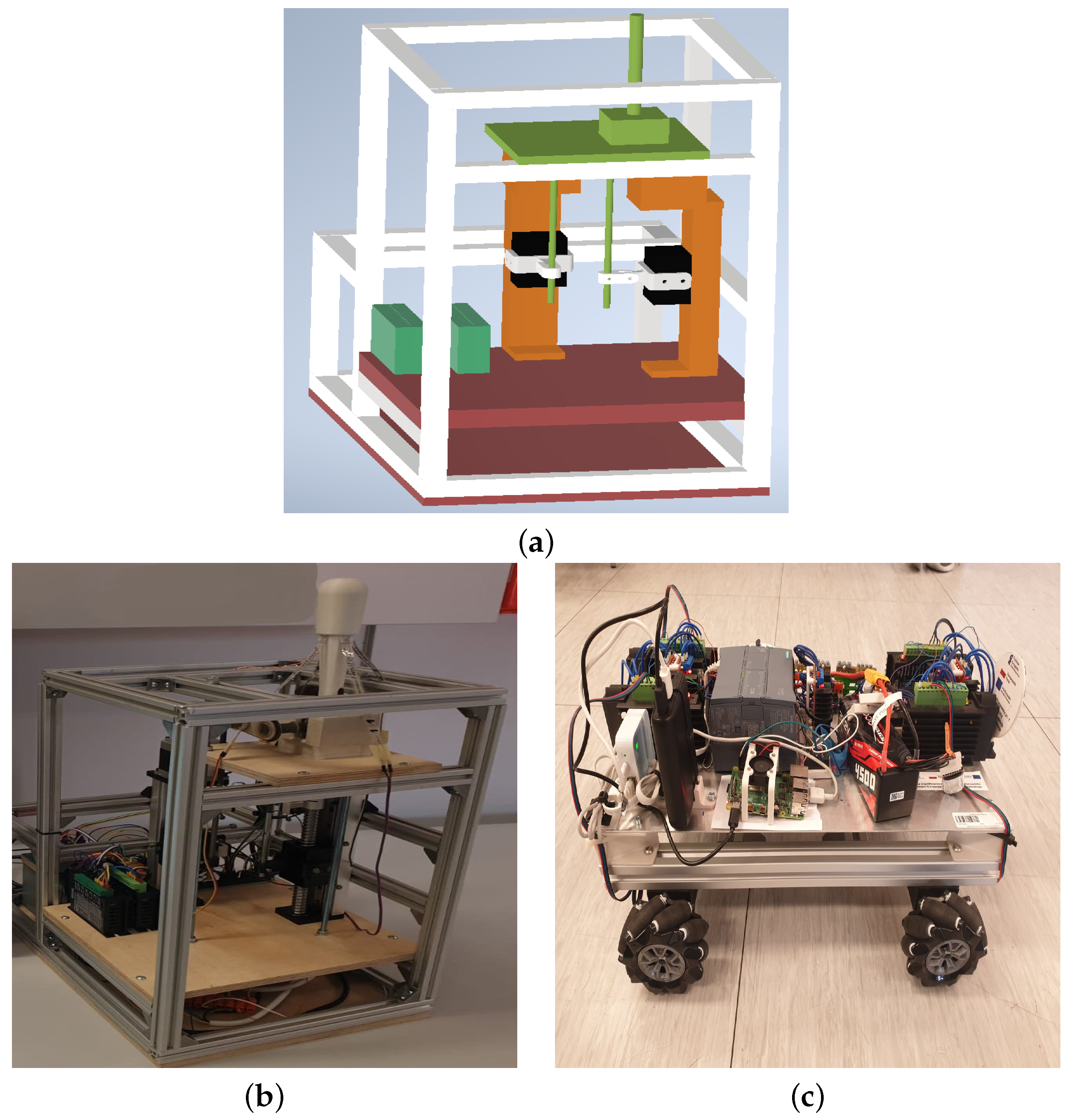
The joystick’s structure is made of aluminum profiles with a base made of wooden plywood (Figure 2a,b). The power supply, Raspberry Pi 4 minicomputer, and auxiliary electronic components are located at the back of the joystick. Two linear drives independently swing the rod in two axes through the rods. Inside the stick are the FSR force sensors and a motor generating vibrations for additional haptic effect. A 3D model of the joystick was created in Autodesk Inventor 2022 to simulate the joystick frame, linear drives, stepper motor controllers, stick with cables, socket, and base, and other assembly elements and to verify their correct execution (Figure 2a). New linear drives were required in a vertical position in the joystick structure, and were assembled along with additional new elements and connections with the rod strings. For this purpose, three-dimensional models were realized, followed by real elements produced via 3D printing.
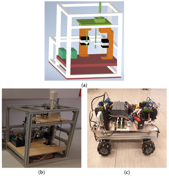
Figure 2.
(a) Design of the joystick, (b) joystick system, and (c) electric vehicle.
The Fused Deposition Modeling (FDM) technique, popularly called 3D printing, was used for the production of components such as the belt-and-gear transmission, gears, and elements of both the vehicle (Figure 2b) and the joystick (Figure 3a). For this purpose, all elements were printed using the MK3S Prusa 3D printer and Ultra PLA material, as shown in Figure 3a–c. The manufactured straight adapter was glued to the block of the linear drive responsible for the tilting of the joystick in the left–right direction. The straight adapter and its the connector transmit the movement of the drive on the rod’s cable, allowing for the cable’s inclination. The side adapter was arranged with the block of the linear drive responsible for tilting the joystick in the front–back direction. The side adapted and connector transfer the movement of the drive to the rod, allowing for free variation of the rod’s inclination. All of the realized elements were then assembled into the joystick structure. The wooden plywood board was located on the base of the joystick stick socket. The limit switches designed to limit the movement of the actuators were installed and mounted on the joystick, screwed into the drive blocks. Finally, the cables and electronic accessories were sorted out by making a dedicated board.
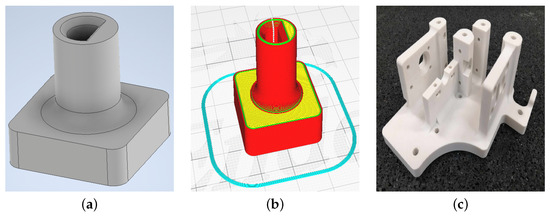
Figure 3.
(a) 3D model of an example element realized in Autodesk Inventor, (b) 3D model in the Ultimaker Cura slicer program, and (c) a printed prototype part of a belt and toothed transmission.
3.2. Joystick Firmware Update: Python Programming Language
A program implemented by the Raspberry Pi 4 minicomputer that controls the joystick’s movement was written in the Python programming language. The beginning of the main executable file contains the one-time execution instructions intended to establish communication with other components of the system and call the initialization function that configures most of the pins on the Raspberry Pi I/O module. The block diagram of the program is presented in Figure 4.
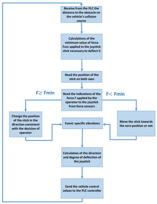
Figure 4.
Block diagram of the main program’s operation.
In particular, the main program code performs the following task:
- FSR sensor readings using an analog-to-digital converter
- the value of the force applied to the stick in four directions
- initialization of the most important variables
- configuration of some pins of the minicomputer’s input–output module,
- definition of functions, including configuration of the pins of the minicomputer’s input–output module, stick deflection conditions, vibration conditions, and calculation of the joystick’s operating parameters
- data transmission support
3.3. Run Tests
The first test of the selected linear drive was carried out using the Arduino microcontroller to reach a specified linear speed of 50 mm/s. The first test program included transmission of a given number of pulses to the step-motor controller at fixed time intervals. The relationship between the period T of pulse transmission and the speed of the linear drive v was calculated using the equation
where v is the linear speed in mm/s, S is the jumping stroke (5 mm), n is the number of pulses for the full-step drive (200), k is the multiplier resulting from the microstep control function, and T is the period of pulses in s.
Despite increasing the microstep control resolution, it was not possible to obtain the target speed. After reaching a certain speed, the motor lost synchronization. For this reason, the program code was changed to include the movement of the motor, systematically reducing the pulse delivery period until it reached the target value. The declared speed of 50 mm/s was achieved with a microstep control resolution 16 times larger than the full step (16×). While maintaining a constant drive speed, the program decreased the sending period every 10 pulses from the initial 70 s to 31 s, for a total of 39 times. According to Equation (1), T = 31 s means that the speed was approximately equal to 50 mm/s. Then, based on the tests carried out using the Arduino microcontroller, commissioning tests were started in the intended target configuration involving direct cooperation of the stepper motor controllers with the Raspberry Pi.
The use of microstep control with the selected resolution (16×) resulted in control pulses being sent every 31 s. The minimum program execution time in the case of Raspberry Pi was approximately 100 s. However, the Arduino board executes the program in the given time increase of 8 s, ensuring much better control of the output pin states. The PWM signal was used for the direct implementation of cooperation between the Raspberry Pi and the controller stepper motor, which can act to control the pulses. The Raspberry Pi can generate a PWM signal in either the software or hardware. Drives with the ability to achieve the expected parameters were selected.
The Raspberry Pi module is necessary for proper operation of the entire haptic feedback system due to the possibility of communication via WiFi. Therefore, the Arduino microcontroller module is used as an intermediary element for communication and control between Raspberry Pi and the stepper motor controller.
The Python program software on the Raspberry Pi implements the ability to tilt the joystick stick and sends information about the joystick orientation and axis deflection to the Arduino. For this purpose, this information is implemented using four digital signals (high and low state); in particular, four pins of the Raspberry Pi I/O module were configured as output and assigned for each direction of driving. The movement of a given drive continues as long as the appropriate state is assigned to the pin. These signals are due to the different voltage levels in the modules (5 V in the Arduino and 3.3 V in the Raspberry Pi) sent through the logic converter. The communication in the other direction is carried out using UART serial transmission, which is used to transmit information about the position of the linear units of both drives, as reported in the program code in Supplementary Materials PC1. Another function is included in the Arduino; a force F of at least 85%, but not greater than the minimum value, should be applied as the minimum force Fmin to deflect the stick at a given moment and to keep the stick of joystick in an intermediate position. The tilting function of the joystick is associated with a change in the conditions of vibration due to the additional haptic effect. The operator should be alert to different types of vibration, such as:
- continuous vibration with intensity of 100%, which is not dependent on the deflection of the joystick because the vehicle is next to the obstacle
- intermittent vibration at 40% intensity when the vehicle is at certain distance from the obstacle, the stick is in the zero position, and the force F applied by the operator is inadequate to deflect the stick and set the vehicle’s speed
Consequently, the linear drives were positioned to produce sufficient tensile force to “overpower” the operator. The operator was notified when the stick reached an intermediate position through intermittent vibrations at 100% force. The communication between the Raspberry Pi and Arduino microcontroller is included in the joystick tilt. In this case, a pin is assigned to activate the drive motors to obtain a holding torque. The stick can be moved by the operator in the right, left, north, and south directions independently to overcome the resistance of the movement of the screw gear in the drives, which is an undesirable effect in the system. When the operator applies a force that is more than the Fmin value while being sufficient to overcome the resistance during movement, the motors are activated. The Arduino nano microcontroller was used between the Raspberry Pi minicomputer and stepwise engine controllers due to the limited space in the back of the joystick. Therefore, an Arduino module was assigned to each drive for calibration and position drives in the zero position, as the joystick does not use an absolute system measuring position and the control system could previously terminate its operation in any stick position. First, the transmission of the left–right axle reaches the switch end position, stops for 300 ms, and then drives away in the opposite direction for half of the drive’s range of motion. After waiting five seconds from startup, the front–rear axle drive performs a reference travel at the same time to avoid overlap. The location of the drive that tilts the stick is stored in the counter variable and counted based on the number of sent control pulses. Every 50 ms, the Arduino scales the drive position value from 0 to 100 and sends this value via serial communication to the Raspberry Pi master unit, as shown in the fragment of the program code in Supplementary Materials PC2.
4. Experimental Results
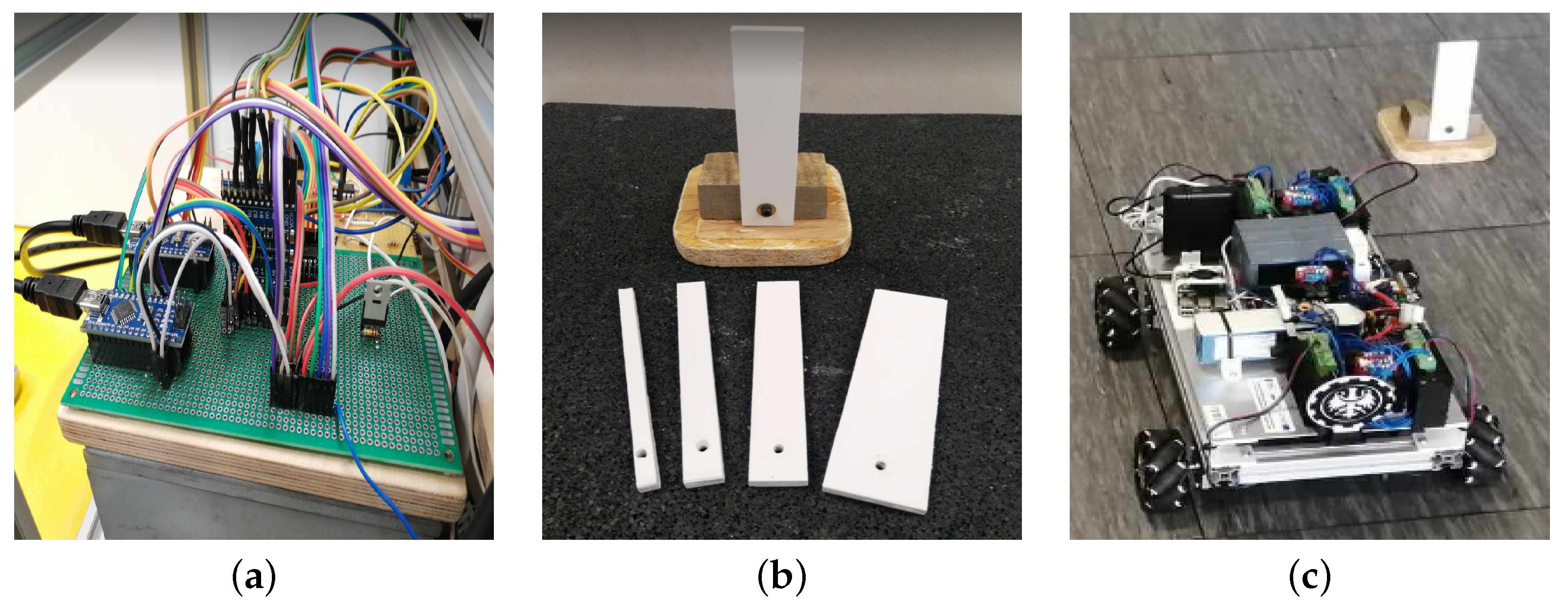
The electronic equipment and Arduino microcontrollers worked on a prototype board in the vehicle, as shown in Figure 5a. The joystick was equipped with the stepper motors and Raspberry Pi and connected to the electric vehicle via WiFi. To control the stepper motor in the joystick, the Arduino controller was used to stop or move the joystick. The analog digital converter can collect signals from force-flexible sensors located on joystick and communicate with the Arduino microcontroller. The PLC receives information about the distance from the obstacle, force applied to the joystick, user’s decision to move the joystick, and calculated direction and speed of the vehicle.
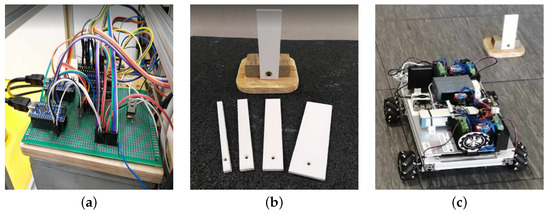
Figure 5.
(a) View of the back of the joystick with dedicated electronic board, (b) view of obstacle with interchangeable plates of different widths, and (c) view of the vehicle with obstacle.
The advantage of this solution is the ease of changing the configuration and connections in the electronic system. Therefore, a dedicated soldered board was made. A universal tile measuring 9 × 15 cm was used as support containing two Arduino microcontrollers embedded in pin sockets, enabling their possible replacement in case of damage. In a similar way, a logic converter was installed to enable communication between the Raspberry Pi and Arduino modules. A transistor and resistors soldered onto the board were used to control the operation of the vibration motor located in the joystick knob and the analog-to-digital converter that processes the signal from the force sensors. The analysis and detection of obstacles was performed in the vicinity of the vehicle operating in the described haptic feedback control system. The RPLiDAR A1M8 laser scanner in the vehicle has the role of detecting obstacles with variable width and the maximum distance received by the joystick. During the tests, the vehicle reached a maximum speed of approx. 0.5 m/s starting from the same place. The obstacles that the vehicle approached consisted of a wooden base and white polystyrene boards with height of 17 cm and various widths of 1, 2, 3, 4, and 5 cm, as shown in Figure 5b. During the tests, an obstacle was placed in a fixed position in a lighted room. In the first stage, the movement of the vehicle was perpendicular to the obstacle in four main directions (0°, 90°, 180°, 270°) (Figure 5c) In the second stage, the vehicle approached perpendicular to the obstacle directions (30°, 150°, 210°, 330°). These directions result from the structure of the vehicle. The RPLiDAR module is located above the structural frame (12 cm from the ground) and below the plate on which the entire structure is located. This plate is mounted on narrow supports that constitute an obstacle to the operation of the scanner precisely in these directions.
Measurements Results
The measurements were conducted in the lighted room of the laboratory, with the vehicle approaching obstacles of different sizes. The currently set speed and the direction of vehicle’s movement released by the direction of the joystick increased the accuracy of the performed measurements. The measurements of the actual distance value between the scanner and the obstacle were scaled from 0 to 100 in the PLC software and then expressed in centimeters. The vehicle detected an obstacle from a certain distance and then again from a closer distance. In the Figure 6a–d, the distribution of measurement points on a symmetrical plane oriented in the same way shows the detection of obstacles made of white polystyrene boards with a height of 17 cm and various widths of 2, 3, 4, and 5 cm. The rings visible in the graphs were determined on the basis of measurements points in the main driving directions (0°, 90°, 180°, 270° and 30°, 150°, 210°, 330°) of the vehicle when it approached the obstacles located in the room.
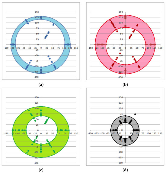
Figure 6.
Distribution of measurement test points in the main and characteristic directions (0°, 90°, 180°, 270° and 30°, 150°, 210°, 330°) for detection of obstacles with widths of (a) 5 cm, (b) 4 cm, (c) 3 cm, and (d) 2 cm located at different distances from the vehicle. Ten measurements were conducted in each direction and with four sizes of obstacle as the vehicle approached the obstacle. The vehicle detects the obstacle from a certain distance, “recognizes” it and stops before the collision, and detects it again at a closer distance than before.
The uniform distribution of the driving directions (0°, 90°, 180°, 270°) in the measurements tests can be observed in Figure 6b,c along with the expected decrease in the distance from which the vehicle recognizes the obstacle as its width decreases. As shown in the graph in Figure 6a,b, for measurements with an obstacle width of 4 and 5 cm the outer edges of the rings have similar diameters, which decrease as the width of the obstacle decreases; as the maximum distance from the obstacle decreases, the vehicle becomes able to detect the obstacle. As the width of the obstacle decreases (Figure 6d), the inner diameter of the rings decreases as well, which means that the expected minimum distance from obstacle also decreases. Measurements with an obstacle of 1 cm width indicate that the system of vehicle is unable to repeatably detect such narrow elements in the vehicle’s surroundings. The highest intensity of intermittent measurements occurred for the obstacle with 4 cm width (Figure 6b). Measurements conducted in the main directions of driving were characterized by a greater difference between the maximum and minimum values of the distance to the obstacle in the individual driving directions. These values depended on the direction of travel of the vehicle. In addition, the system achieved the worst results in detecting obstacles for the 30° direction. The measurement points for this direction of travel are closest to the middle point of the graph. Thus, obstacles located in the front or right part of the vehicle have the greatest impact on scanning the surroundings. Comparing the test results, it can be concluded that the system detects obstacles more effectively in the main directions. The measurements tests for these directions were mainly located in the areas marked by the inner edge of the rings. It can be concluded that although the obstacles in the 30° direction had the greatest influence, the other obstacles interfered with the detection as well. Measurements conducted with the 1 cm obstacle in all eight tested directions indicate that the system is not able to repeatably detect such narrow elements in the vehicle’s surroundings.
5. Conclusions and Perspectives
In this activity, the new design of a joystick equipped with stepper motors and linear drives is proposed, with efficient wireless communication via WiFi with an electric vehicle with four omnidirectional wheels. The drive units are used within the joystick and control algorithms of the entire system, and the measurement stick deflection and communication between individual joystick components are analyzed. In this system, the joystick is not tilted through the operator, instead being based on two independent linear drives to produce enough tensile force/pressure to “overpower” the operator. Python program software on a Raspberry Pi is used to implement the ability to tilt the joystick and send information about the joystick orientation and deflection axis to an Arduino microcontroller. The basic haptic effect is the increase in the minimum value of the pressure force applied to the joystick rod that permits it to be deflected. Test measurements were conducted involving obstacle detection in a lighted room in the main directions perpendicular to the electric vehicle, along with the maximum speed reached and maximum distance received by the joystick. The main limitation of the realized electric vehicle system is due to the LiDAR used in the electric vehicle to obtain accurate information on the environment, which only works well in an illuminated room. Because LiDAR uses light beams to measure the locations of objects, it can be difficult to capture data in small or dark areas, and its accuracy is highly dependent on the quality and calibration of the system’s scanner. Thus, future works need to consider using new technologies based on sensors that can process of the data and recognise inconsistencies or inaccuracies.
Supplementary Materials
The following supporting information can be downloaded at: https://www.mdpi.com/article/10.3390/computers13020048/s1, PC1: code1; PC2: code2.
Author Contributions
Conceptualization, K.A.D., P.K. and G.L.S.; methodology, K.A.D.; software, K.A.D.; validation, K.A.D., P.K. and G.L.S.; formal analysis, K.A.D., P.K. and G.L.S.; investigation, K.A.D.; resources, K.A.D. and P.K.; data curation, K.A.D., P.K. and G.L.S.; writing—original draft preparation, K.A.D., P.K. and G.L.S.; writing—review and editing, K.A.D., P.K. and G.L.S.; visualization, K.A.D., P.K. and G.L.S.; supervision, P.K.; project administration, P.K.; funding acquisition, P.K. All authors have read and agreed to the published version of the manuscript.
Funding
This research was supported by the Excellence Initiative-Research University Programme at the Silesian University of Technology, 2023.
Institutional Review Board Statement
Not applicable.
Informed Consent Statement
This article does not contain any studies with human participants or animals performed by any of the authors.
Data Availability Statement
The datasets generated during and/or analyzed during the current study are available from the corresponding author on reasonable request.
Conflicts of Interest
The authors declare no conflicts of interest.
References
- Zhou, H.; Jia, F.; Jing, H.; Liu, Z.; Güvenç, L. Coordinated longitudinal and lateral motion control for four wheel independent motor-drive electric vehicle. IEEE Trans. Veh. Technol. 2018, 67, 3782–3790. [Google Scholar] [CrossRef]
- Ding, X.; Wang, Z.; Zhang, L. Hybrid control-based acceleration slip regulation for four-wheel-independent-actuated electric vehicles. IEEE Trans. Transp. Electrif. 2020, 7, 1976–1989. [Google Scholar] [CrossRef]
- Weiskircher, T.; Müller, S. Control performance of a road vehicle with four independent single-wheel electric motors and steer-by-wire system. Veh. Syst. Dyn. 2012, 50, 53–69. [Google Scholar] [CrossRef]
- Ding, X.; Wang, Z.; Zhang, L.; Wang, C. Longitudinal vehicle speed estimation for four-wheel-independently-actuated electric vehicles based on multi-sensor fusion. IEEE Trans. Veh. Technol. 2020, 69, 12797–12806. [Google Scholar] [CrossRef]
- Long, S.; Terakawa, T.; Yogou, M.; Koyano, R.; Komori, M. Kinetic analysis of active omni wheel with barrel-shaped rollers for avoiding slippage and vibration. J. Mech. Robot. 2024, 16, 051002. [Google Scholar] [CrossRef]
- Hijikata, M.; Miyagusuku, R.; Ozaki, K. Omni Wheel Arrangement Evaluation Method Using Velocity Moments. Appl. Sci. 2023, 13, 1584. [Google Scholar] [CrossRef]
- Komori, M.; Matsuda, K.; Terakawa, T.; Takeoka, F.; Nishihara, H.; Ohashi, H. Active omni wheel capable of active motion in arbitrary direction and omnidirectional vehicle. J. Adv. Mech. Des. Syst. Manuf. 2016, 10, JAMDSM0086. [Google Scholar] [CrossRef]
- Macfarlane, A.B.; van Niekerk, T.; Becker, U.; Mercorelli, P. Control system strategy of a modular omnidirectional AGV. In Modeling, Identification, and Control for Cyber-Physical Systems Towards Industry 4.0; Elsevier: Amsterdam, The Netherlands, 2024; pp. 169–197. [Google Scholar]
- Zhao, T.; Qin, P.; Dian, S.; Guo, B. Fractional order sliding mode control for an omni-directional mobile robot based on self-organizing interval type-2 fuzzy neural network. Inf. Sci. 2024, 654, 119819. [Google Scholar] [CrossRef]
- Ismael, O.Y.; Almaged, M.; Abdulla, A.I. Nonlinear Model Predictive Control-based Collision Avoidance for Mobile Robot. J. Robot. Control (JRC) 2024, 5, 142–151. [Google Scholar]
- Borkar, K.K.; Aljrees, T.; Pandey, S.K.; Kumar, A.; Singh, M.K.; Sinha, A.; Singh, K.U.; Sharma, V. Stability Analysis and Navigational Techniques of Wheeled Mobile Robot: A Review. Processes 2023, 11, 3302. [Google Scholar] [CrossRef]
- Samada, S.E.; Puig, V.; Nejjari, F. Robust TS-ANFIS MPC of an autonomous racing electrical vehicle considering the battery state of charge. IEEE/ASME Trans. Mechatronics 2023, 28, 656–667. [Google Scholar] [CrossRef]
- Guevara, L.; Jorquera, F.; Walas, K.; Auat-Cheein, F. Robust control strategy for generalized N-trailer vehicles based on a dual-stage disturbance observer. Control Eng. Pract. 2023, 131, 105382. [Google Scholar] [CrossRef]
- Zhou, X.; Wang, Z.; Wang, J. Automated Vehicle Path Following: A Non-Quadratic-Lyapunov-Function-Based Model Reference Adaptive Control Approach With C-Smooth Projection Modification. IEEE Trans. Intell. Transp. Syst. 2022, 23, 21653–21664. [Google Scholar] [CrossRef]
- Zou, Q.; Sun, Q.; Chen, L.; Nie, B.; Li, Q. A comparative analysis of LiDAR SLAM-based indoor navigation for autonomous vehicles. IEEE Trans. Intell. Transp. Syst. 2021, 23, 6907–6921. [Google Scholar] [CrossRef]
- Zheng, K. Autonomous Obstacle Avoidance and Trajectory Planning for Mobile Robot Based on Dual-Loop Trajectory Tracking Control and Improved Artificial Potential Field Method. Actuators 2024, 13, 37. [Google Scholar] [CrossRef]
- Laghmara, H.; Boudali, M.T.; Laurain, T.; Ledy, J.; Orjuela, R.; Lauffenburger, J.P.; Basset, M. Obstacle Avoidance, Path Planning and Control for Autonomous Vehicles. In Proceedings of the 2019 IEEE Intelligent Vehicles Symposium (IV), Paris, France, 9–12 June 2019; pp. 529–534. [Google Scholar] [CrossRef]
- Li, S.; Li, Z.; Yu, Z.; Zhang, B.; Zhang, N. Dynamic Trajectory Planning and Tracking for Autonomous Vehicle with Obstacle Avoidance Based on Model Predictive Control. IEEE Access 2019, 7, 132074–132086. [Google Scholar] [CrossRef]
- Wang, P.; Gao, S.; Li, L.; Sun, B.; Cheng, S. Obstacle avoidance path planning design for autonomous driving vehicles based on an improved artificial potential field algorithm. Energies 2019, 12, 2342. [Google Scholar] [CrossRef]
- Almazrouei, K.; Kamel, I.; Rabie, T. Dynamic obstacle avoidance and path planning through reinforcement learning. Appl. Sci. 2023, 13, 8174. [Google Scholar] [CrossRef]
- Hu, Z.; Su, R.; Zhang, K.; Xu, Z.; Ma, R. Resilient Event-Triggered Model Predictive Control for Adaptive Cruise Control Under Sensor Attacks. IEEE/CAA J. Autom. Sin. 2023, 10, 807–809. [Google Scholar] [CrossRef]
- Hu, Z.; Su, R.; Wang, Y.; Wang, B.; Huang, L.; Lu, Y. Security Enhancement for Longitudinal Vehicle Platooning Under Denial-of-Service Attacks: From Resilient Controller Design Perspective. IFAC-PapersOnLine 2023, 56, 1088–1093. [Google Scholar] [CrossRef]
- Sciuto, G.L.; Kowol, P.; Nowak, P.; Banás, W.; Coco, S.; Capizzi, G. Neural network developed for obstacle avoidance of the four wheeled electric vehicle. In Proceedings of the 2023 30th IEEE International Conference on Electronics, Circuits and Systems (ICECS), Istanbul, Turkey, 4–7 December 2023; pp. 1–4. [Google Scholar] [CrossRef]
- Kowol, P.; Nowak, P.; Banaś, W.; Bagier, P.; Lo Sciuto, G. Haptic Feedback Remote Control System for Electric Mechanical Assembly Vehicle Developed to Avoid Obstacles. J. Intell. Robot. Syst. 2023, 107, 41. [Google Scholar] [CrossRef]


Disclaimer/Publisher’s Note: The statements, opinions and data contained in all publications are solely those of the individual author(s) and contributor(s) and not of MDPI and/or the editor(s). MDPI and/or the editor(s) disclaim responsibility for any injury to people or property resulting from any ideas, methods, instructions or products referred to in the content. |
© 2024 by the authors. Licensee MDPI, Basel, Switzerland. This article is an open access article distributed under the terms and conditions of the Creative Commons Attribution (CC BY) license (https://creativecommons.org/licenses/by/4.0/).