1. Introduction
The vast majority of systems currently used in our daily life are software-intensive systems, meaning that a significant percentage of their components is of software type. The software element makes such systems complex and subject to frequent maintenance due to continuously changing requirements. Complexity and requirements management are aspects to be properly addressed in the development of software components, because they are both related to the dependability of a system. Applying changes to an overly complex software product can easily lead to the introduction of regression faults. As stated in the literature (see, e.g., [
1,
2]), requirements definition and analysis are the most critical activities in the development of software components, due to the required effort and the impact of requirements change on dependability and software cost.
Dependability is a crucial characteristic for so-called critical systems, i.e., systems whose failure or malfunctioning may lead to severe consequences. In [
3], the authors categorize critical systems as (a similar, simplified classification is also found in [
4])
safety-critical (may lead to loss of life, serious personal injury or damage to the natural environment),
mission-critical (may lead to an inability to complete the overall system or project objectives),
business-critical (may lead to significant tangible or intangible economic costs) and
security-critical (may lead to loss of sensitive data through theft or accidental loss).
This paper proposes an approach for the process-oriented requirements definition and analysis of software components in critical systems, with a focus on
business-critical ones. In particular, the approach supports the definition of a formal, standard model that links requirements, processes and data through the use of several standards, namely the Business Process Model and Notation (BPMN) [
5], the Systems Modeling Language (SysML) [
6], the Decision Model and Notation (DMN) [
7] and the Shared Data Model and Notation (SDMN) [
8].
The integration of these four formalisms makes it possible to specify the relationships between requirements and process elements that satisfy them, and the data consumed/produced by such process elements. In addition, the resulting model achieves a complete system specification, which includes both the behavioral view, which deals with the specification of functional aspects, and the structural view, which deals with specification of static data-related aspects.
The proper integration of these two views is a well-known problem in both systems engineering and software engineering [
4].
When the addressed system is critical, each view must be carefully modeled in a separate way by using different types of UML/SysML diagrams, and the problem of a unified view is addressed at a later stage by analyzing the interactions between the two models, e.g., by using sequence diagrams that model the allocation of activities onto structural elements in a given execution scenario.
In this paper, we focus on the specification of the behavioral view, which is annotated with so-called ad hoc attributes (according to [
9]), so to drive a more detailed system specification in the SysML. The proposed contribution introduces a stepped approach that progressively refines the system specification, from models at higher levels of abstraction, which are effectively used to help stakeholders defining their own requirements, down to more detailed models, which provide the requirements specification used to feed the subsequent system development and maintenance activities. Specifically, the approach takes as an input BPMN models annotated with ad hoc attributes and integrates DMN and SDMN models to finally yield the system model specified in the SysML as an output.
As such, the initial focus on the behavioral view, which is annotated with only those data necessary to properly execute a given scenario, does not preclude a subsequent refinement of the data model with the full details of the data consumed/produced at execution time.
The integrated model is a key ingredient for effective requirements management, specifically in terms of traceability and V&V (verification and validation). The proposed model indeed enables the adoption of simulation-based approaches that are essential components of the so-called
digital twin, a concept introduced by M. Grieves to denote a virtual copy of the actual system which is tightly coupled with its physical counterpart and used for efficient and effective system management [
10]. A digital twin indeed includes continuous data exchange between the system model and the actual system, thus making the model and the system constantly aligned [
11]. Real-time data collected from the system can be used both to monitor system execution and to feed the model with accurate and up-to-date parameters that allow one to “execute” the model by use of simulation-based approaches. In turn, system simulation provides those predictive capabilities that are essential for informed decision making and prompt reaction to system failures or performance downgrades. As such, the proposed model can be considered as a first step towards the development of a digital twin that leads to significant advantages in terms of proper monitoring and steering of the actual system.
The rest of the paper is organized as follows.
Section 2 provides some background material about the main standards used in the paper, while
Section 3 summarizes the related work.
Section 4 describes the proposed approach, which is then detailed in
Section 5 by use of a running example application. Finally,
Section 6 discusses the presented approach and gives concluding remarks.
3. Related Work
A vast amount of literature covers approaches dealing with requirements definition and analysis in both the systems engineering and software engineering domains [
12]. This section is not intended to provide an exhaustive review of these approaches but rather to compare and motivate the proposed contribution with respect to similar works.
Requirements definition is known to be a critical activity at both software development and maintenance stages, due to the significant impact that a faulty requirement has in terms of repair cost throughout the software lifecycle. A relevant source of error that may lead to the introduction of defects in requirements can be traced to the different roles that contribute to the definition of requirements, from stakeholders and business analysts with expertise in the application domain but no specific software engineering skills to engineers and IT developers in charge of translating high-level requirements into an operational system [
13].
The different points of view on the system to be developed and its requirements, as well as a very different technical background, may easily lead to misunderstandings and ambiguities which imply effort- and time-consuming rework activities. Model-based approaches have shown significant potential as an effective means to face these issues by introducing semi-formal requirements definition approaches that stand in between easy-to-use informal approaches, based on the use of natural language and thus being prone to ambiguity, and costly formal approaches, based on the use of mathematical specifications requiring skills which in many cases business analysts and developers are not familiar with [
14].
In this respect, in [
9], the authors propose the introduction of ad hoc data models in the requirements elicitation phase, in order to make such requirements easy to understand and verify by stakeholders and, at the same time, unambiguous for the IT developers. This paper contribution exploits this idea to introduce ad hoc annotations to the BPMN model that defines the starting point of the proposed approach.
In order to properly manage requirements, once they have been defined, it is important to have the ability to describe and follow their use at development and maintenance time, in both a forward and backward direction. This ability is named
requirement traceability and has an important role in Model-Based Systems Engineering (MBSE). Several works in the field of systems engineering achieve requirements traceability by using the MBSE and SysML (see, e.g., [
15,
16]). In [
17], the authors present a traceability approach that supports decision-making requirements by combining the SysML with the BPMN and DMN. The SysML is used to model some aspects of system, and processes and decision-making activities are defined in terms of the BPMN and DMN standards, respectively. Such a result provides a useful input to properly integrate the behavioral view of the BPMN model with the structural view of the SysML model through the DMN and SDMN models.
The next section outlines the approach proposed in this paper, which is then detailed by use of a running example in
Section 5.
4. The Three-Step Aepproach
As stated in
Section 3, this paper’s approach to process-oriented requirement analysis is inspired by the lightweight BPMN extension presented in [
9], where ad hoc attributes (AHAs) are defined as a set of
key properties which get a specific
graphical representation in the BPMN model for the system to be developed, with
visual hints that make it easier to read and understand how such properties guide the execution flow and the requirements satisfaction. Ad hoc attributes may be in turn real properties of the entities involved in the requirement or
synthetic/derived properties, easier to understand for the non-developer but formally linked to the underlying real system data model through potentially complex algorithms. In this way, stakeholders have a simplified higher-level and requirement-oriented view of the system, which is easier to validate, whereas developers can easily map such a view to the real system in order to develop the requirement implementation.
Our approach maps the BPMN models extended with ad hoc attributes to a formal, standard model that links requirements, processes and data through the use of several standards: BPMN 2.0 [
5], the System Modeling Language (SysML) [
6], the Decision Model and Notation (DMN) 1.3 [
7] and the Shared Data Model and Notation (SDMN) [
8].
The choice to start from the AHA-annotated models comes from their focus on the behavioral view of the system, thanks to the compatibility with the BPMN standard, and their lightweight integration with data, given by the ad hoc attributes. This makes the whole process easily accessible, at the requirement specification level, to a variety of stakeholders and, on the other hand, it also simplifies the integration with the other standards described above.
The approach consists of the following three steps:
Step 1: from BPMN-AHA models to BPMN and DMN models. In the first step, requirements modeled as in [
9] are represented through a combination of standard BPMN and DMN models. In particular, Data Objects, i.e., sets of variables, are used to represent the information consumed and produced by tasks as well as to indicate the data used in the DMN Decision Tables. Moreover, in order to deal with the ad hoc data model of [
9], further Data Objects may be used to model the
dynamic entities associated to the execution of specific fragments of a BPMN process. In other words, temporary entities that are not made persistent by being created and consumed at the process execution time only. In addition, the visual hint introduced in [
9], which is conventionally represented as a color applied to areas of the BPMN model, is determined by a special Business Rule Task, which updates a specific Data Object holding such information. Each BPMN Business Rule Task is attached to a corresponding DMN Decision Table that, given the input Data Objects, applies its business knowledge model to generate or update data in the output Data Objects.
Step 2: data representation with SDMN. All the Data Objects involved in the BPMN model and all the data elements in the DMN models should have a common formalization, e.g., through UML class diagrams. Such formal data representations are then mapped to the SDMN DataItems and linked to the BPMN and DMN Item Definitions, thus defining a single shared and formal data representation.
Step 3: SysML model specification. Finally, in the last step, all the elements defined in the previous steps are suitably linked together using the SysML Requirement Diagrams and Block Definition Diagrams. In particular, Requirement Diagrams are used to formalize the relations and the hierarchy between requirements, whereas Block Definition Diagrams are used to represent the process elements, data, the relationships among them and the requirements.
The details of the three steps are given in the next section, which introduces a simple yet comprehensive case study that is used as a running example application of the proposed approach.
Finally, it is worth noting that the process we present here is strictly one-way: any change proposed by any stakeholder in any intermediate step determines a reset of the process itself, i.e., the change must be reflected on the initial model and the following integration steps must be performed again. Indeed, this kind of constraint comes from the intrinsic nature of the systems we address, i.e., critical systems, where the introduction of a change in any point of the system design and development should trigger a complete re-analysis of the system itself (or at least of the containing subsystem if the system is well-architectured), since it may determine dangerous side effects elsewhere.
5. Example Application
Let us consider the case of a request for a bank loan by a customer, i.e., a simplified version of the
Originations example presented in [
7]. In particular, let us address the following requirements:
- R1
If the applicant is less than 18 year old or is an existing customer with a risk score less than 80 (lower risk scores correspond to higher risk levels, as described in the original example specification [
7]), the application is rejected. If the applicant is an existing customer and his risk score is between 80 and 110, the application is subject to a preliminary analysis. Finally, all the applications go through a review process which determines their acceptance or rejection.
- R2
The application procedure must be processed within 3 days, otherwise a delay notification has to be sent.
5.1. Lightweight Model with the AHA Approach
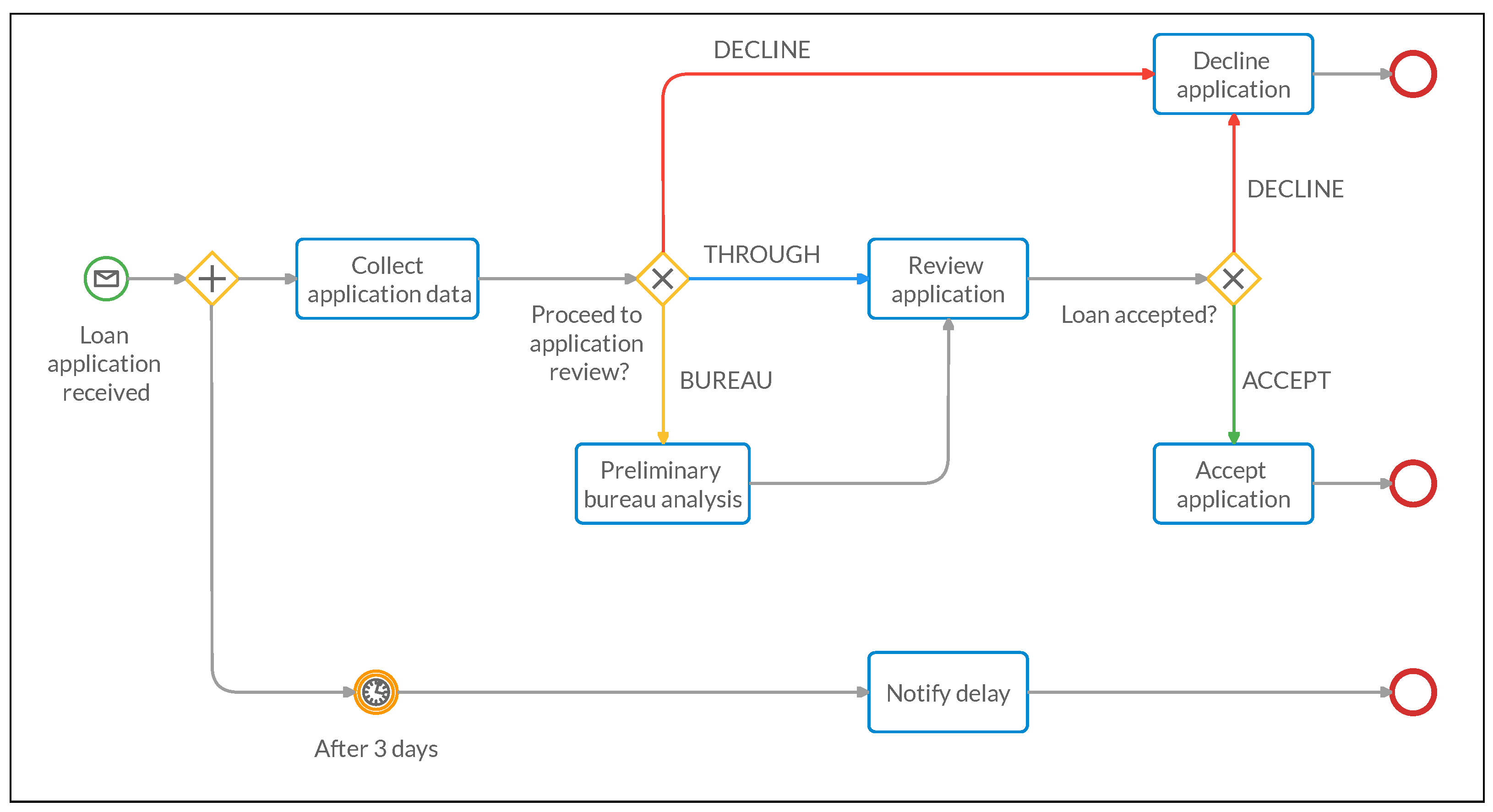
By applying the AHA methodology, these requirements are clearly modeled through the BPMN process shown in
Figure 1 using the ad hoc data model described in
Table 1. In the latter, the
application entity contains the dominant
status attribute which expresses, through the associated colors, all the possible application review and decision statuses derived from requirement (1) above. The
Applicant entity is populated with the only, possibly derived applicant information that is required to simply derive the status above, i.e., his
age, his
risk score and a flag indicating if he is an
existing customer.
At the flow start, we collect the application data and applicant data in the Application and Applicant entities, respectively. Then, the
Proceed with application review? gateway uses the Application
status attribute derived from
Table 1 to redirect the flow to the
Decline application task if the status is red (
decline), to the
Preliminary bureau analysis task if the status is yellow (
bureau) or directly to the
review application task if the status is blue (
through). After the review, the updated
status is finally used in the
Load accepted? gateway to decide for the decline (red) or accept (green) application task.
5.2. Medium-Weight Model with BPMN, DMN and SDMN
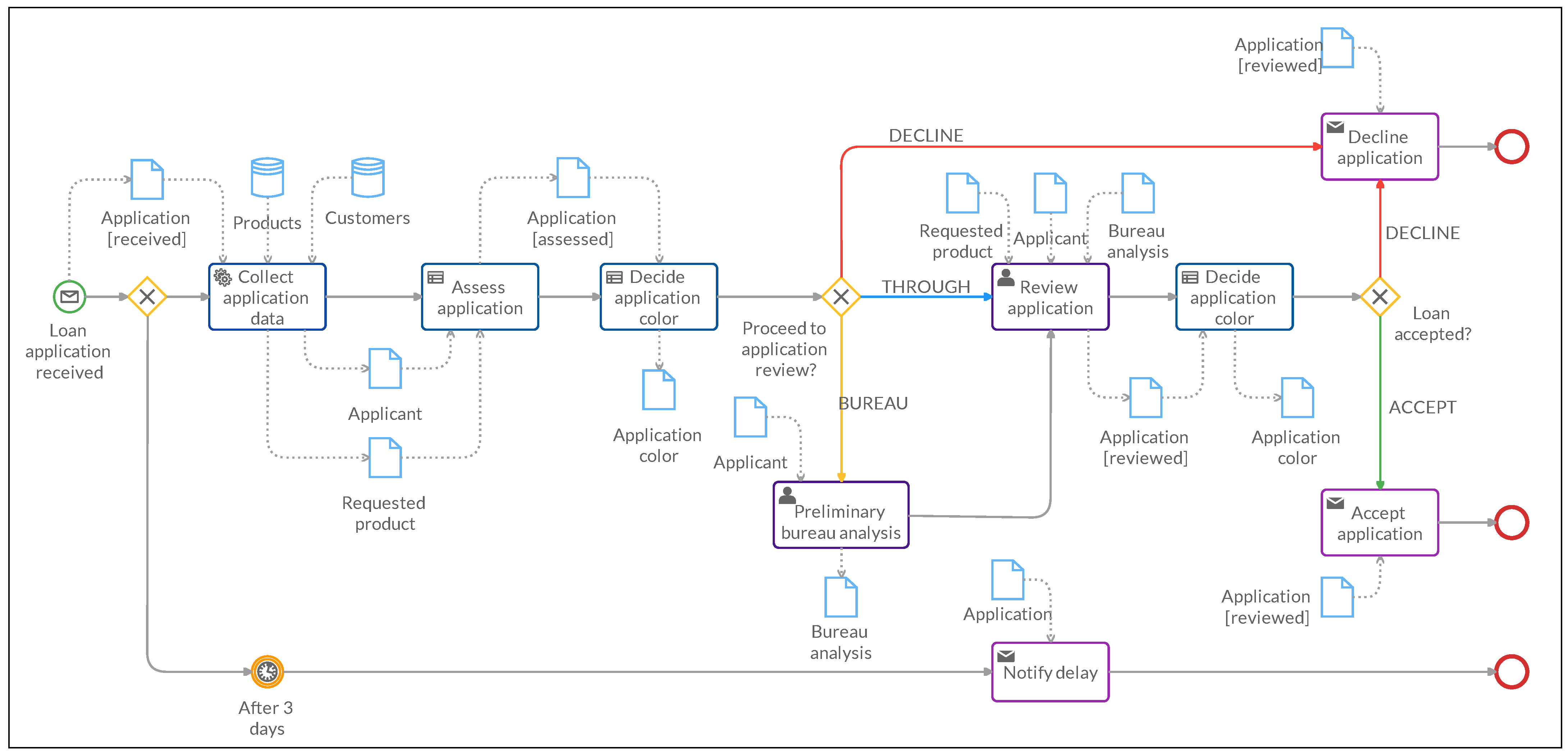
Starting from this lightweight ad hoc model, we can generate a medium-weight formal model by enriching the given BPMN process with Data Objects to represent the data involved in each task, Data Associations to represent the data flow and Business Rule tasks invoking DMN decision models to encapsulate the BPMN extensions semantics of the AHA model. The resulting BPMN is shown in
Figure 2 and can be described as follows.
Here, at the flow start, the application is modeled through a corresponding
Application Data Object containing the requested
product, the applicant
name and the application
status. The flow then splits in two possible flows: in the first, after 3 days, a delay is notified to the applicant (using the
Application Data Object) and the process ends. Otherwise, the
Collect application data task uses the
Application Data Object and the
Customers and
Products Data Stores to generate the
Applicant (name, age, existing costumer, risk score) and
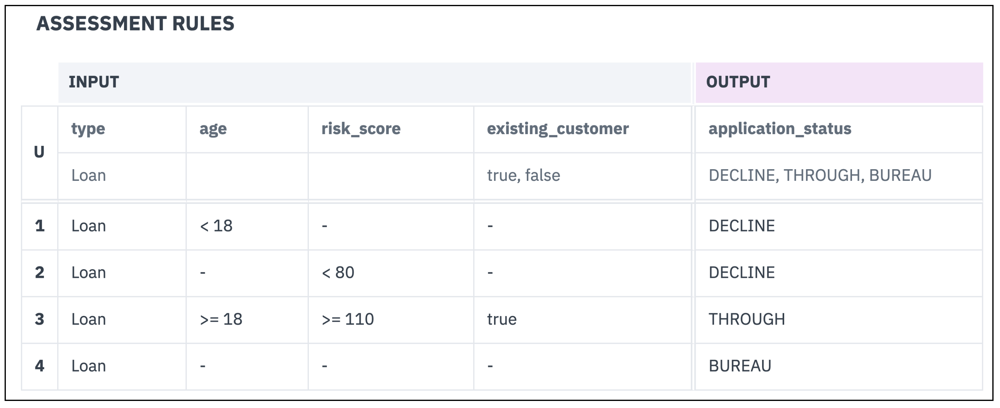
Requested product (type, amount) Data Objects. Next, the Business Rule Task
Assess Application takes as input the last two Data Objects and applies requirement (1) above. To this aim, the decision table associated to this task uses the
product type, applicant
age, applicant
risk score and applicant
existing customer properties from the input Data Objects and generates an output application status, which is written in the
Application Data Object. In particular, the corresponding business knowledge model follows the decision table shown in
Figure 3:
Regardless of the the risk score and existing customer values, if the value of age is less than 18 the status is decline;
Regardless of the customer age, if the risk score is less than 80 the status is decline;
If the age value is greater than or equal to 18, the risk score is greater than or equal to 110, and the customer is known (existing), the status is through (i.e., the application can skip the preliminary analysis);
In all the other cases, regardless of the age, risk score and existing customer the status is bureau, i.e., the application requires a preliminary analysis.
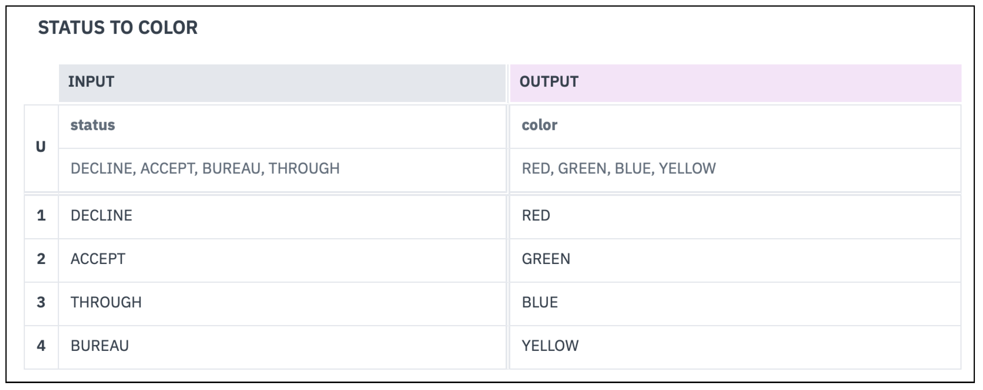
Next, the Business Rule Task
Decide Application Color takes the updated Application Data Object as the input and associates it with a color, which is written in the Application
color attribute. In particular, the corresponding business knowledge model uses the
status to color decision table shown in
Figure 4. It takes the application
status and generates the output
Application color Data Object, where the color is
red if the status is
decline,
green for
accept,
blue for
through and
yellow for
bureau.
It is worth recalling here that the application color is an handy visual aid introduced in the AHA model to quickly identify the data that actually guide the process evolution and its discriminant values. We feel it could be also useful to maintain and trace such synthetic attribute in the following integration steps, for the sake of readability. However, it is not strictly needed for the procedure described here, so it could be left only in the AHA model and omitted from the following ones.
At this point, the gateway Proceed to application review? working on the color attribute devised above activates one of the possible three scenarios:
Red (decline) activates the Decline application Send Task;
Yellow (bureau) activates Preliminary bureau analysis User Task where, starting from the Applicant Data Object, the report is produces and encoded in the Bureau analysis Data Object, and in particular in its risk category and bankrupt attributes. The flow then continues to the Review application User Task described in the next point;
Blue (through) takes directly to the Review application User Task, where the three Data Objects Requested product, Applicant and Bureau analysis are used to perform a final check on the application, whose status is updated.
If the flow has not been terminated (red), the next step is always another Decide application color Business Rule Task, which uses the same status to color business knowledge model to update the Application color attribute based on the updated Application status.
Finally, the Load accepted? gateway uses such color to determine the final application outcome:
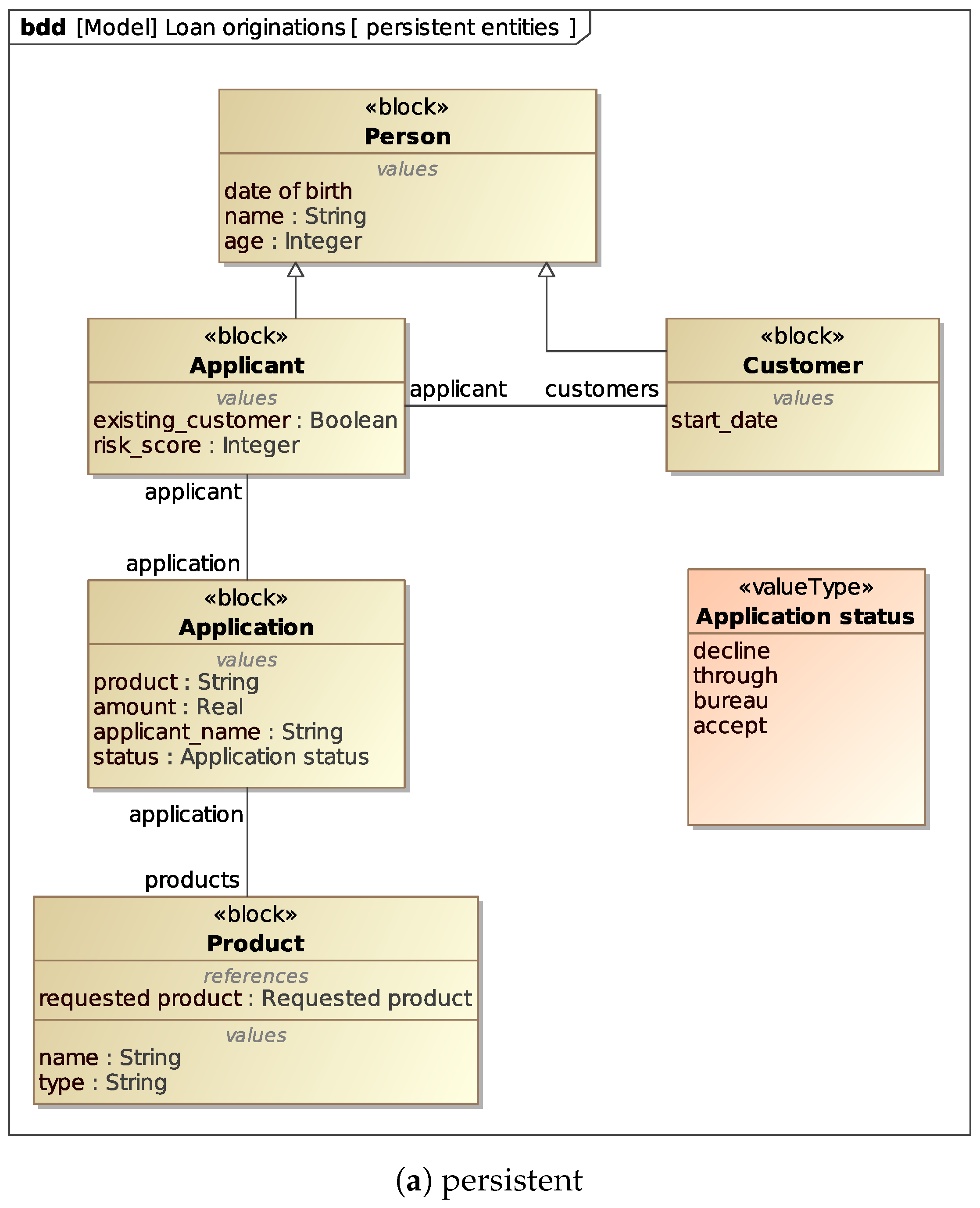
In the BPMN above, we reference several Data Objects. We may assume that some of them, i.e., Applicant, Application and Product, correspond to real persistent entities contained in the actual system implementation. Therefore, we assume to have (or reconstruct from the sources) a formalization of these objects such as the UML class diagram shown in
Figure 5a. In particular:
Applicant inherits the base attributes from Person and adds existing_customer and risk_score.
Customer also inherits the base attributes from Person and adds the start_date attribute indicating the date from which the person started to be a bank customer. This attribute is used to derive the existing_customer attribute of the Applicant, if the latter is a (existing) Customer.
Application is the loan application requests, with the product, applicant_name, amount and status attributes.
Product represents a product class through its name and type attributes. Each Application references exactly one of these products.
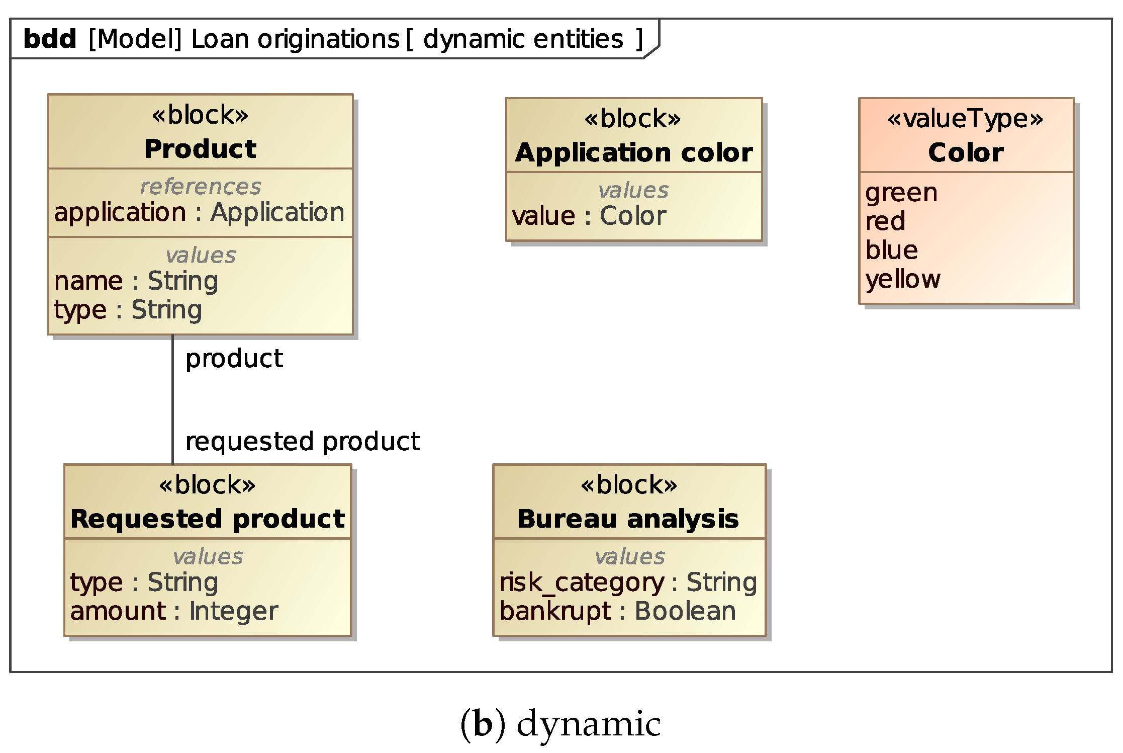
Other Data Objects involved in the BPMN model, i.e.,
Requested product (generated by the
Collect applicant data task) and
Application color, are clearly internal to the process and exists only during its execution. We call them
dynamic entities. For the sake of simplicity, we include a formalization of such entities in the class diagram, as in
Figure 5b, although they are not present in the system implementation. Anyway, in general we make no hard assumptions on the availability of such class diagrams for dynamic entities.
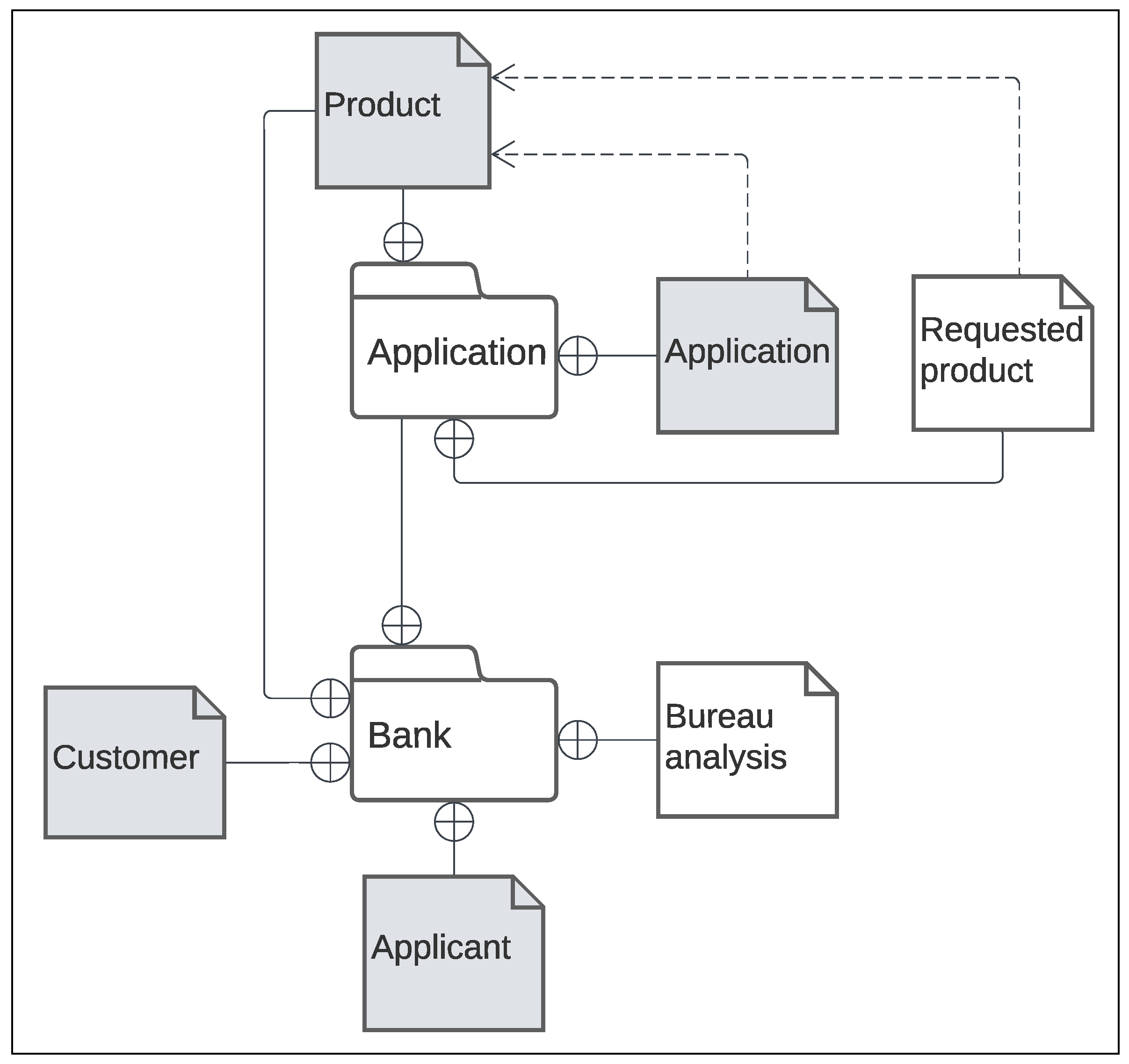
Finally, a SDMN diagram is used to link such structural models to the BPMN and DMN Item Definitions, as shown in
Figure 6, where dynamic entities are depicted in white background and static (persistent) entities in gray background. According to the SDMN specification, the background color used for the graphical elements is white, but the notation may be extended to use other background colors for specific purposes (e.g., to highlight different types of entities, as it is in this paper case).
5.3. Heavyweight Formalization with SysML
In the last phase of the proposed process, we move the formalization a step forward with the help of the SysML, and get to a heavyweight formalization that paves the road for requirements management, traceability and verification. In particular, we use the SysML Requirements Diagrams and Block Definition Diagrams to link requirements to process elements and data items.
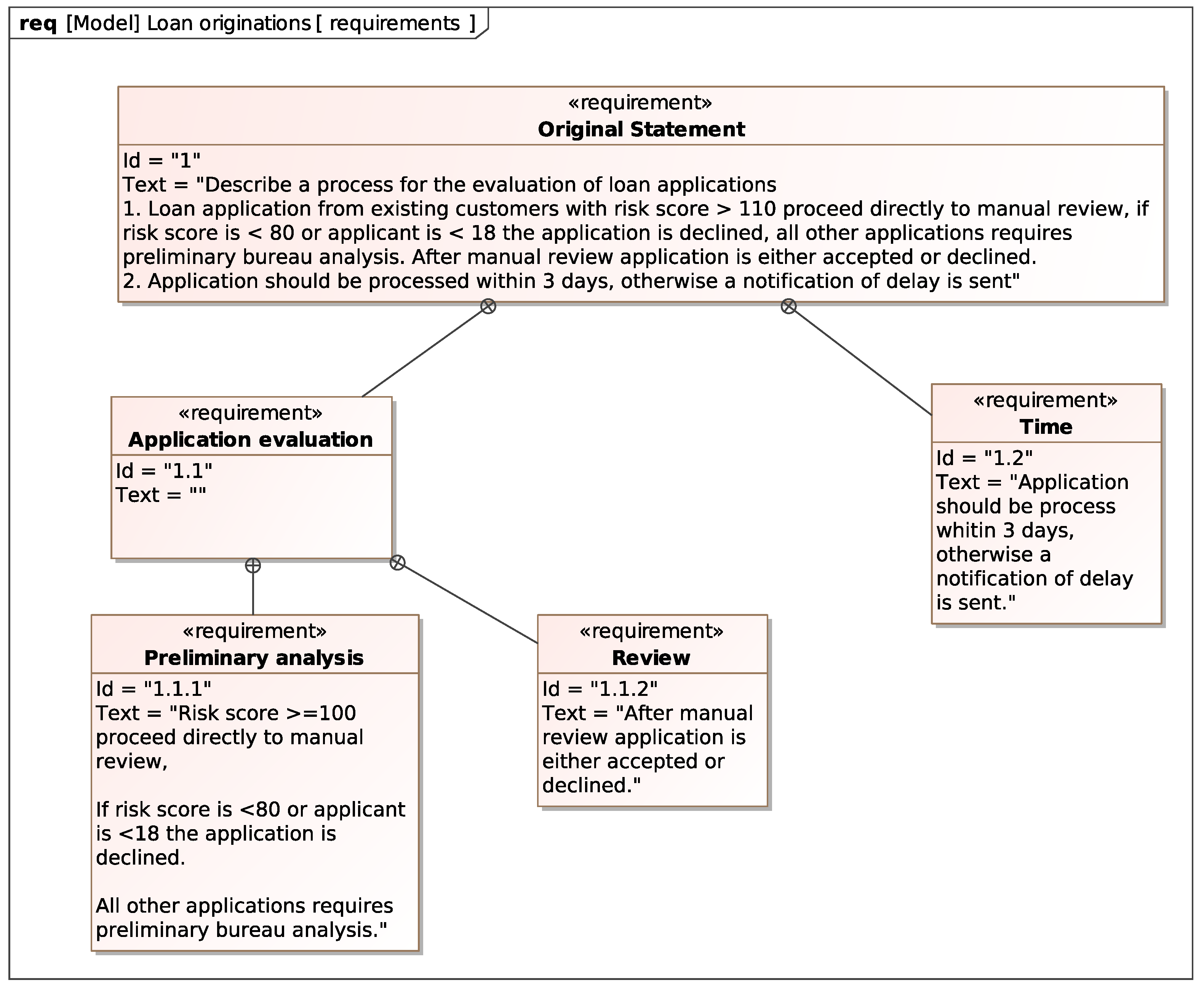
The two requirements considered for the loan application example can be modeled with the Requirement Diagram shown in
Figure 7. The diagram defines a compound requirement named
Original Statement that contains all the requirements the process must satisfy. These requirements contain the atomic requirement
Time and the compound requirement
Application evaluation, which in turn contains
Preliminary analysis and
Review. As we will show, this requirement hierarchy helps to visualize the traceability from the requirements to the system model elements depending on them.
The UML class diagram introduced in
Section 5.2 (
Figure 5) to formalize the process data corresponding to persistent and dynamic entities can be turned into a Block Definition Diagram without any loss of information, as is shown in
Figure 8a,b, where we use
Value Types to model the possible values that data items in the process can take.
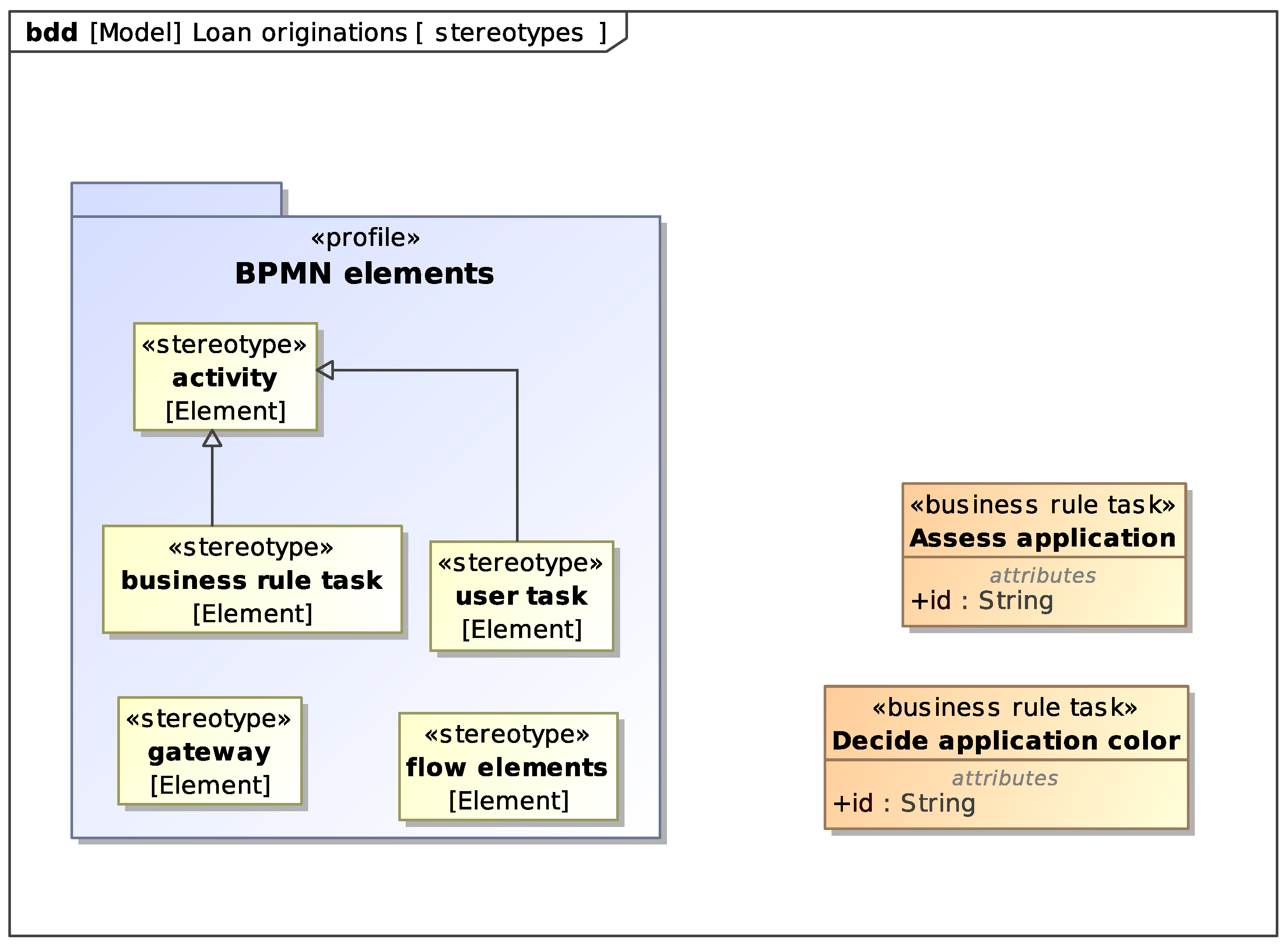
To link elements of the SysML model with elements in the BPMN model we adopt an approach similar to the one used in [
17]. We introduce a
profile and define
stereotypes for the BPMN elements that satisfy our requirements.
Figure 9 shows the stereotypes we need:
Activity represents BPMN activities. In particular, Business Rule Tasks and User Tasks. We use an attribute named id to store in the SysML models the ID of the corresponding element in the BPMN model.
Gateway represents BPMN gateways.
Flow elements represents a set of BPMN elements that together satisfy a requirement.
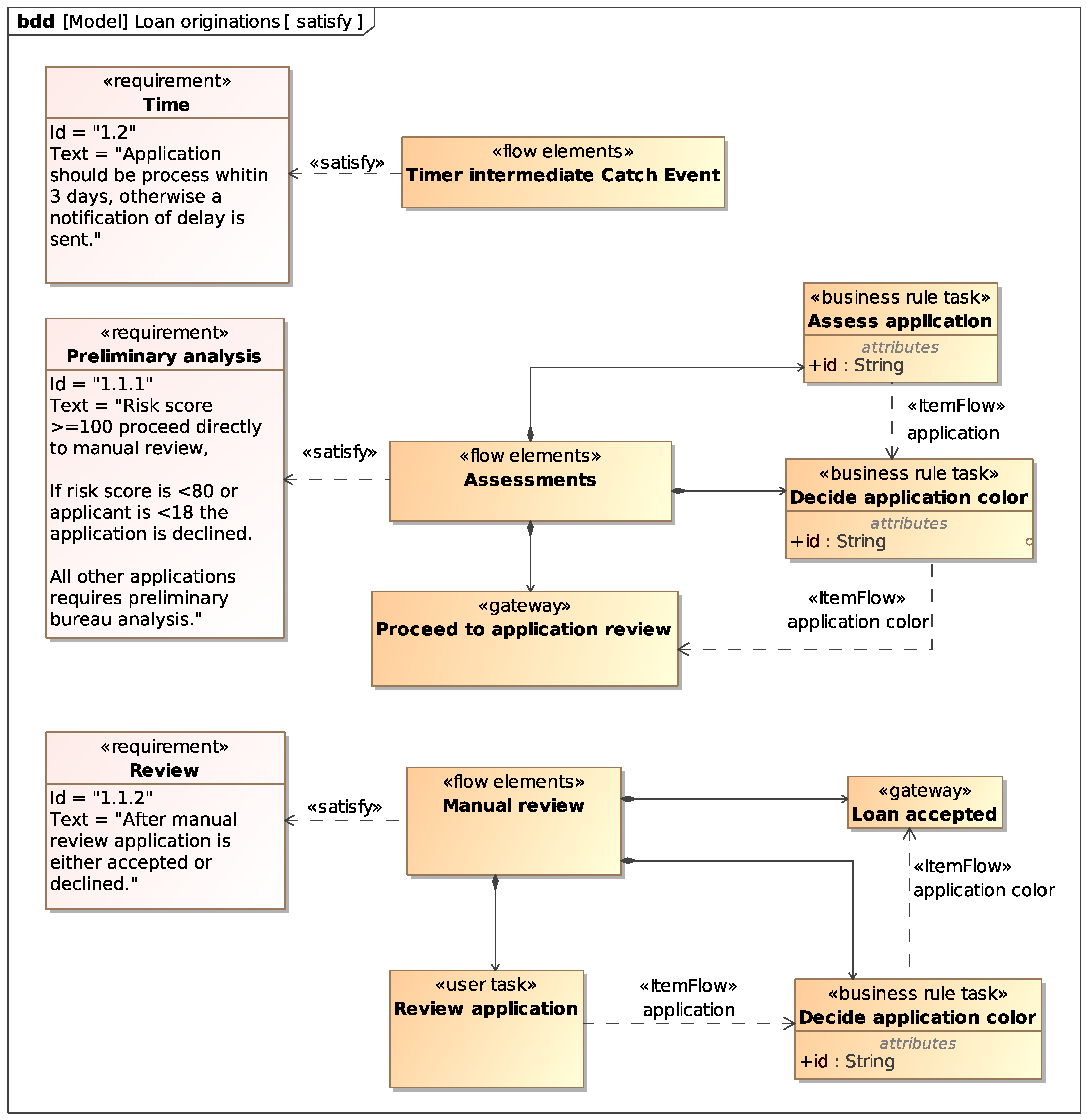
With the defined stereotypes we can use blocks to model BPMN elements in the SysML model. We connect such blocks to requirements via
satisfy relations to show which elements of the process satisfy which requirement. Moreover, we use item flows between blocks representing BPMN elements to indirectly relate data items to requirements.
Figure 10 shows the blocks representing the BPMN elements that satisfy the loan application atomic requirements and the item flows between them.
This heavyweight formalization provides a series of advantages in terms of requirements analysis and management. The satisfy relations and stereotypes help in tracing BPMN elements to requirements and vice versa, thus documenting process design choices with respect to requirements. The SysML model, together with the BPMN, DMN and SDMN models, can be the unique source of truth in a software system that supports change management, for example, by automatically determining which requirements could be affected by a change in process or data.
5.4. Constraint Formalization and Requirement Verification
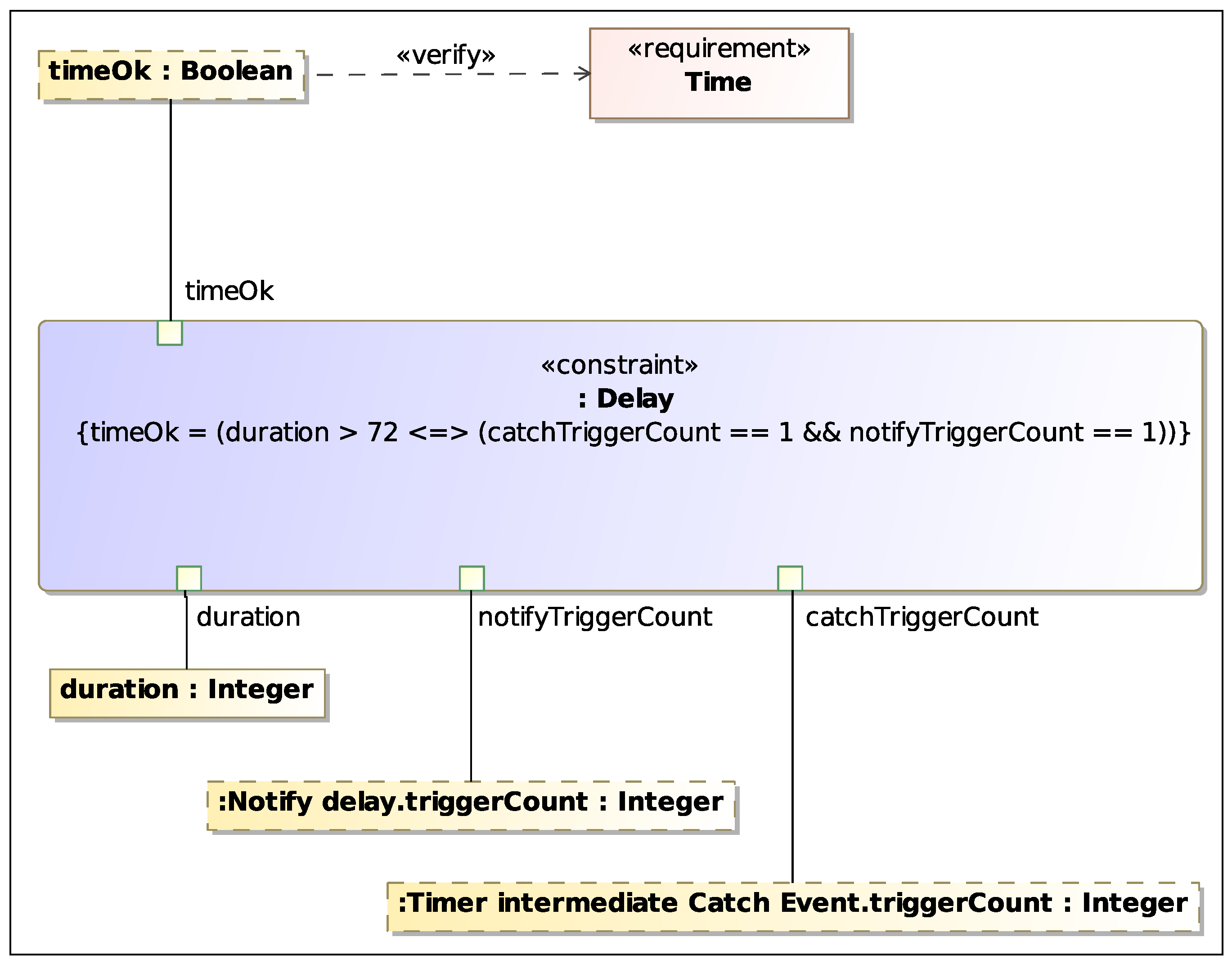
The heavyweight formalization may also set the basis for the automatic requirement verification. Indeed, using Constraint Blocks it is possible to define formal and/or informal equations that verify whether a given requirement is satisfied or not. In our context, the properties that can verify our requirements and act as parameters in the equations are process parameters such as, e.g., the duration of a task, the duration of the process or the number of times an event occurs.
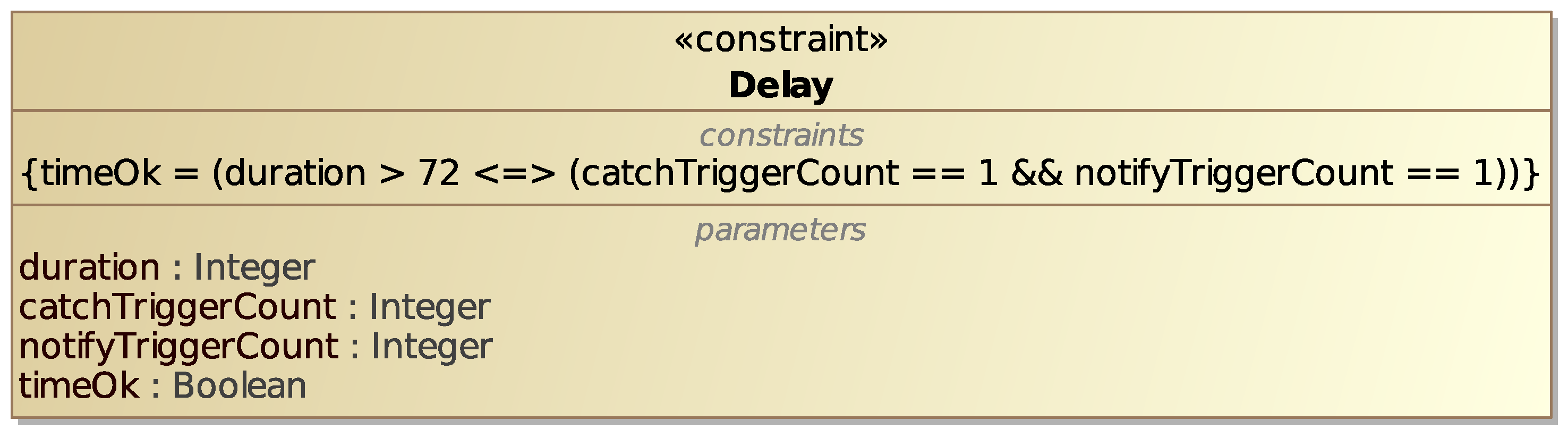
As an example, an informal equation for the Time constraint in
Figure 7 could be the one shown in the constraint block
Delay shown in
Figure 11. Here,
is the execution time in hours for the whole process,
is the number of times the
After 3 days Intermediate Timer Catch Event is triggered and
is the number of times the Send Task
Notify delay is run. The right side of the equation states that the event is triggered and the task is run if and only if the process lasts for more than 72 h (i.e., 3 days). The
variable computed by the equation tells us whether the Time requirement is satisfied or not.
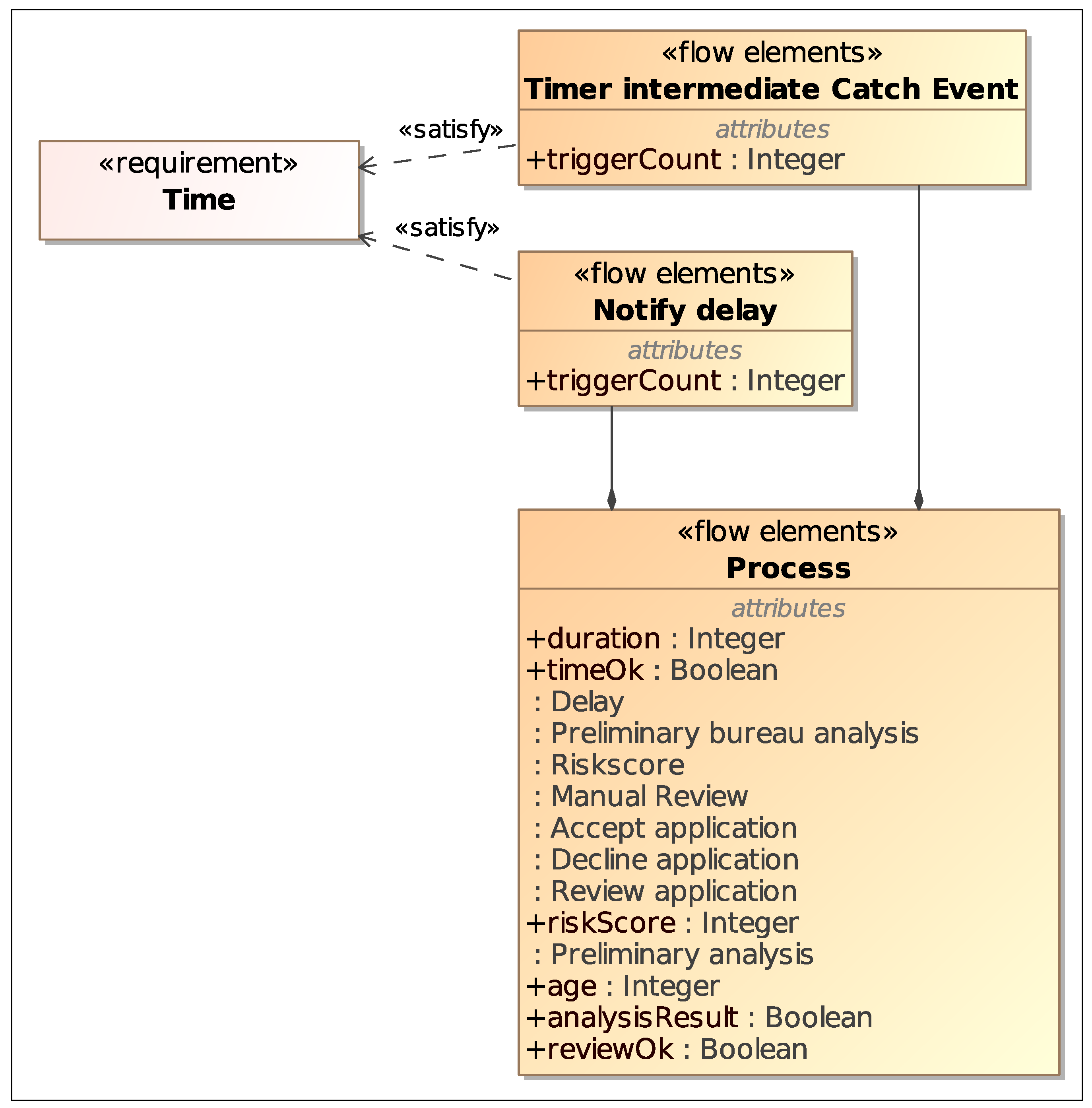
Figure 12 shows a revised version of the blocks for the process elements, with the addition of new blocks and properties that model process parameters related to the constraint equation variables.
Finally, with a
Parametric Diagram it is possible to connect such constraint variables to properties of the BPMN elements block, and visualize the
verify relationship between the Time requirement and the
property of the
Process block, as shown in
Figure 13.
With a similar setup in place for each requirement, and having a system that evaluates the constraints given the values of the process properties, it would be possible to automatically verify the requirements. Moreover, by using a tool for process simulation based on the Business Process Simulation (BPSim) [
18] standard, one could map the block properties involved in the constraints to the equivalent BPSim parameters, and then use simulations to generate the values to use for the requirement verification. Process simulation could then be used to perform different types of analysis, from the evaluation of the effects of process changes on the requirements, to the identification of edge cases leading to requirement violations.
It is worth noting that the formalization of the integrated system model allows one to largely automate the verification step using model-driven approaches that take as an input the system model and yield as an output the corresponding simulation model ready to be executed, as described in [
19,
20].
6. Conclusions
In this paper, we presented an approach that supports the definition of a formal, standard model linking requirements, processes and data.
In particular, we propose a three-step approach that starts from requirement definitions formalized using AHA-BPMN, a lightweight BPMN extension, and transforms it in a combination of standard BPMN, DMN decision models and Data Objects. Data Objects are then further formalized using UML class diagrams and linked to BPMN and DMN artifacts through SDMN diagrams. Finally, we use SysML Block Definition Diagrams to link these elements to the requirements modelled through Requirement Diagrams.
This final formalization helps in tracing BPMN elements to requirements, and can be used as the basis for simulation-based automatic requirement verification, which will be the main part of our future research. In this respect, the proposed approach can be considered as a first step towards the development of a digital twin that leads to significant advantages in terms of proper monitoring and steering of the physical system.
The approach has been presented by use of a simple but effective case study which, however, does not exclude its application to more complex processes that may include critical paths, errors and anomalies. In fact, the BPMN standard introduces several elements to model how errors and anomalies are managed in a process, such as boundary events and event sub-processes. The complexity of the model, measured in terms of number of elements, can be controlled with approaches such as the hierarchical modeling style described in [
21]. At the same time, the SysML diagram used in the final step can be considered as agnostic with respect to the system requirements and the BPMN elements that satisfy them.
Moreover, the presented approach makes it possible to work on models in an incremental and iterative fashion, for example, by starting with the success paths and gradually adding more elements to represent the additional paths in the process. Indeed, work is in progress to implement a software tool that supports our methodology. Such a tool would include a facility to navigate the different levels of the model, as well as the management of the large number of paths that may show up in the BPMN model once a relevant number of exceptions is taken into account.
With the help of such a tool, we will be able to apply our approach to a wider variety of different, realistic case studies, in order to validate its generality and also to collect data useful to present some effectiveness measures. Indeed, as already pointed out, our “heavyweight model” can be considered the basis for the realization of a digital twin of a critical business process; therefore, our idea is to exploit a digital-twin-specific quality metric, e.g., [
22] to evaluate it.

 ,
, 


