Abstract
In this study, an effective local minima detection and definition algorithm is introduced for a mobile robot navigating through unknown static environments. Furthermore, five approaches are presented and compared with the popular approach wall-following to pull the robot out of the local minima enclosure namely; Random Virtual Target, Reflected Virtual Target, Global Path Backtracking, Half Path Backtracking, and Local Path Backtracking. The proposed approaches mainly depend on changing the target location temporarily to avoid the original target’s attraction force effect on the robot. Moreover, to avoid getting trapped in the same location, a virtual obstacle is placed to cover the local minima enclosure. To include the most common shapes of deadlock situations, the proposed approaches were evaluated in four different environments; V-shaped, double U-shaped, C-shaped, and cluttered environments. The results reveal that the robot, using any of the proposed approaches, requires fewer steps to reach the destination, ranging from 59 to 73 m on average, as opposed to the wall-following strategy, which requires an average of 732 m. On average, the robot with a constant speed and reflected virtual target approach takes 103 s, whereas the identical robot with a wall-following approach takes 907 s to complete the tasks. Using a fuzzy-speed robot, the duration for the wall-following approach is greatly reduced to 507 s, while the reflected virtual target may only need up to 20% of that time. More results and detailed comparisons are embedded in the subsequent sections.
1. Introduction
The number of robots deployed in the manufacturing industry has increased drastically in recent times [1]. The Internet of Things (IoT) enables autonomous and mobile robots to interact with their surroundings, sense obstacles, navigate through defiance patterns, perform a certain task, and be involved in many autonomous interactions [2]. Robots are believed to be the key enablers of industry 5.0, especially in manufacturing. When a human user initiates a task, robots that observe the process using visionary sensor devices, such as the use of a mounted camera, can then aid the workers within the production space. Robotic applications are increasingly being adopted in healthcare systems as well. The COVID-19 pandemic, for instance, has seen the use of Robots for the purpose of collecting samples from patients. Robots were also used to disinfect common spaces with larger traffic, such as in hospital entrances and supermarkets [3]. Robots are envisioned to be the key enablers for personalized healthcare systems providing assistance to patients and the elderly [4,5].
Within industrial spaces, in unmanned aerial vehicle (UAV) applications, commonly known as a drone, cameras play an important role in observing the environment the drone may encounter—particularly in adverse weather events. Thus, navigational solutions, such as those proposed in [6,7], rely on the use of automated camera-based systems to improve the navigation and landing of UAVs. However, in confined spaces, such as in warehouse settings, collaborative robots should consider the presence of humans, objects, and manufacturing machines to avoid any potential accidents in the operational space. Therefore, robots need a plan to travel safely to arrive at the final specified target and to avoid any incidents within their navigated path. Navigational environments are the medium in which robots are deployed. Generally, they are different types of robots. Their characteristics vary, such as their size and shape. They possess different capabilities as well, such as the obstacles’ avoidance mechanism they use. Given the natural complexity of the environment they operate in, robots require tailored path planning schemes. For example, path planning for indoor environments should consider the existence of walls and narrow channels, such as corridors. Navigating a robot through unknown environments or within indoor manufacturing traffics is prone to several navigational challenges, including those relating to local minima. Such encountered challenges may prevent the robot from reaching its destination or accomplishing its mission. The local minima resulting from common shapes of obstacles, including U-shaped, E-shaped, or V-shaped, constrains the robot from moving forward and reaching its target freely by limiting the navigational area of the robot [8,9]. The problem of local minima emanates when the robot keeps repeating the same steps infinitely. This navigational problem appears mostly in U-shaped obstacles and mazes. Since the robot always follows many steps in the navigation algorithm, it could become stuck in an infinite loop by repeating the steps defined in its algorithm without being able to reach the target destination. This local minima issue is also referred to in the literature as “limit cycle” [10],” deadlock” [11], “dead end”, “cyclic dead end”, or “trap-situation” [12]. To this end, this paper makes the following contributions:
- An improved and novel algorithm is proposed for the detection and avoidance of local minima.
- The proposed algorithm encompasses five approaches to effectively avoid obstacles, including V-shaped, double U-shaped, C-shaped, and cluttered environments, without falling into the local minima. Mainly, the approaches involve changing the target point temporarily and placing a virtual obstacle covering the local minima region in order to force the robot out of deadlock.
- Several experimental works were set up to evaluate the performance of the five proposed approaches. The results indicate that the Local Path Backtracking approach has the best performance among the five proposed approaches, followed by the Reflected Virtual Target approach.
- Additionally, the results demonstrated that the proposed approaches are quite reliable. For instance, in cluttered environments, the time and distance required to reach a destination by a robot were reduced by eight times when compared to other traditional approaches.
- Overall, the simulation results of the proposed system showed an enhancement in the time required to reach the target in most of the five proposed approaches, especially in the wall-following approach.
This paper is organized as follows: Section 2 describes the main challenges mobile robots face during path planning. Section 3 summarizes the related works. Section 4 describes the base system that the proposed approaches rely on and the fuzzy speed controller employed by the proposed approaches. The proposed approaches to overcome the local minima problem and simulation results are provided in Section 5. Section 6 concludes the paper, and potential future directions are given in this section.
2. Challenges in Online Path Planning
This section is devoted to a brief review of the challenges encountered by robots in path planning. Typically, in online path planning, the robot is expected to overcome several major and minor challenges, such as those reported in [13]. The main challenges are briefly summarized below.
2.1. Obstacle Avoidance
A robot must have a kind of sensory system to avoid collisions with obstacles in the workspace. These systems use various sensors, including ultrasonic sensors, stereo cameras, infrared transceivers, and laser range finding sensors (LIDAR, Light Detection and Ranging). A successful navigation system must be aware of obstacles scattered in the navigation environment at every move; thus, many studies proposed methods to avoid obstacles. The majority of these studies used common approaches in this field, some of which include the use of fuzzy systems [14,15,16], neural networks [17,18,19], and Virtual Potential Fields [20,21,22,23,24].
2.2. Goal Seeking, Loops and Speed
Goal seeking is a destination that the robot has to reach at the end. A robot that terminates in a location other than the target is said to have failed its mission. Cyclic dead ends or loops are also one of the serious challenges encountered while designing and implementing a robot navigation system. Controlling the speed of the robot depending on the surrounding environment is equally important as well. The focus of this paper is to evaluate solutions to address these challenges. These possible solutions can reduce the time needed for the robot to reach the target. In real-life applications, such as space robots, robots employed to help rescue missions in catastrophic conditions, and robots deployed in military applications, reducing the time that a robot takes to reach a target point is considered crucial and critical.
3. Literature Review
A recent study discussed the potential and limitations of robots and their connections to other machines to the progress of Industry 4.0 initiatives. Manufacturing, agriculture, kitchen and domestic applications, robotics for healthcare practices, automotive sector, and logistics and warehouse are some of the major potential capabilities of robotics in many industries. Robots are programmed to have a particular amount of intelligence, which is growing as sensor technology improves, not only to do different jobs but also to make decisions, including its adaption in working environments. However, industrial robots need specialized operation and continuous maintenance and development [25]. Whereas Industry 4.0 concentrated mostly on quality, flow, and data collecting, Industry 5.0 focuses more on highly-skilled humans and robots working side-by-side to or even together to develop personalized goods for the consumer. Robots may perform some routine tasks, such as heavy lifting, transportation of raw parts and merchandise, etc., while trained employees focus more on cognitive tasks and creativity. Robots in Industry 5.0 contribute to the reduction in production cost and to an increase in productivity [26]; however, navigational issues, such as path planning and avoiding the local-minima problem in indoor settings, remain amongst the key challenges to their proliferation. On this front, solutions that aim to improve the indoor navigational systems of robots have been previously proposed. The aim is to automate the navigation of Mobile Robots with minimal human intervention. Thus, enabling numerous smart IoT-based applications. For instance, in [27], a multi-sensor fusion approach has been proposed to improve the aerial navigation of robots in industrially-restricted environments. Other works, such as those reported in [28,29] proposed the use of vision-based object recognition solutions to improve the navigation of mobile robots. However, these solutions are generally considered costly and require the use of special sensing devices (e.g., mounted camera and image processing capabilities). Furthermore, ref. [30] proposed a solution to local minima on path planning in unknown environments. In their work, they analyzed patterns in the readings gathered from sensors, where the readings of a sensor compromise two pieces of information; the time when the obstacle is sensed and the location where the robot sensed the obstacle. A similar study in [31] mainly depends on the analyses of spatio-temporal patterns. These patterns were classified to ease recognition of a deadlock situation. The classification also used a two layered-scheme that contains a neural network followed by a fuzzy system. The study shows good performance measured by the length of the path followed by the robot to reach the target point. Another methodology to overcome the local minima problem is proposed in [32]. The local minima situation was defined as a robot following the steps B C B D B, where each of B, C, and D were places already visited by the robot. The solution to the local minima problem was divided into three stages; detection, definition, and avoidance. The environment of navigation was perceived as a grid G, a two-dimensional array. The grid was composed of n square cells, and each cell is represented as C(i)(j). To define the local minima location and size, the proposed approach in [32] built a corresponding map to the grid that showed the explored occupied cells in the grid during navigation. Each cell was represented by a positive integer that incremented each time the robot detected an obstacle occupying the cell. After a local minimum was detected and its enclosure was defined, the robot traveled to a safe destination out of the deadlock enclosure and then closed the enclosure by a virtual wall placed at the entrance of this enclosure, which can be identified by a special laser finding sensor on the robot on the next visit. In addition, some studies [33,34] use the Bug algorithm [35] and its variations to keep the robot away from falling into traps.
Other studies [9,24,36] tried to solve the local minima problem using the wall following approach. This is a popular approach used to get the robot out of a maze by following the walls. This method produced successful results in many environments. However, it suffers from two major weaknesses; firstly, the method fails to reach a target point outside the maze if it follows a wall forming a closed shape. Secondly, the robot must stop following the wall at some point if the target is inside the maze. The success of a method using the wall following technique depends on its ability to determine the point at which the robot should stop following the wall appropriately, for example, in [36], the authors propose a new deadlock detection algorithm that uses the readings of the sensors to determine the size and place of the deadlock. This algorithm keeps running with every set of new sensors’ readings to determine the point at which the robot must stop following the wall and be set into target tracing mode again. Although one of its major problems is local minima, many studies use artificial potential field methods for path planning.
5. Addressing the Local Minima Problem by Target Switching
This section introduces the novel algorithm proposed in this work. The algorithm encompasses approaches that aim to detect the local minima and approaches to get the robot out of the deadlock enclosure. All of the approaches use the same proposed detection algorithm because of its precision and ability to detect the trap situation effectively. Moreover, the five approaches with the detection algorithm were compared to the wall-following approach used in [9]. The same base navigation system proposed in [9] was used for obstacle avoidance and goal-seeking.
5.1. Environment Perception
The navigation environment was perceived as a grid composed of n cells. One major problem that should be discussed is the partially occupied cells. This problem arises in most navigation systems that depend mainly on grids when the robot cannot move to a partially occupied cell, even when there is not enough space for the robot to traverse this cell. The problem is illustrated in Figure 2. To avoid this problem, the robot does not depend on the grid cells to find the next move. Instead, the robot uses an independent navigation system proposed in [9] to navigate between obstacles. This means that the grid is only used for local minima detection and avoidance while using the independent navigation system, the robot keeps tracking and updating location information in terms of cells. In [9], the action taken by the robot at any time depends on the immediate mapping of the ultrasonic sensory data. However, the robot has no memory or fuzzy speed mechanism where our contribution addresses these important features.
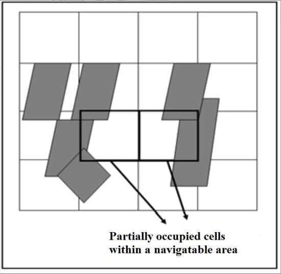
Figure 2.
The problem of partially occupied cells.
The number of cells (n) in the grid can be found using Equation (2):
where n is the number of the cells in the grid, A is the rectangular area of the environment, and is the size of the robot. This means that there are cells, where L is the length of the environment, and is the length of the robot. The robot in [9] gets its location at every movement step using the turning angle, and the distance from the starting point. This location information can be used to find the robot’s location in terms of a cell using the following formulas:
where in (Equation (3)) and (Equation (4)), x and y are the x-coordinates and y-coordinates, respectively, for the robot’s current location. At each location update, the robot found its current location within the grid and stored the cell’s index in the Vistited_Cells vector. For example, the visited cells in Figure 3 are given by a vector of spatial data (2,5), (3, 4), (3,6), (3,7), (4,7). Note that the icon of the robot in Figure 3 becomes a dark square when the local minima algorithm is activated, and a circle in an independent navigation system, such as in [9]. When traversing a cell (i), the robot tests three situations:
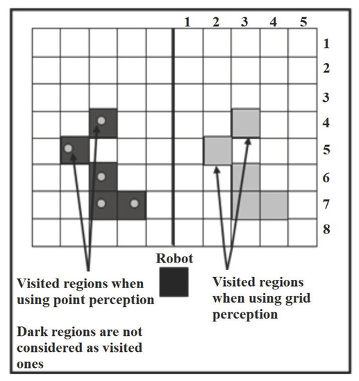
Figure 3.
The difference between the effectiveness in cell perception and point perception.
- If the cell does not exist in Visited_Cells, then it is added to the vector, and the number of visits for the current cell NV(i) is increased by 1.
- If the cell already exists in the vector, and the robot is still traversing the same cell with multiple steps (i.e., within the same cell’s borders), then do nothing.
- If the cell already exists in the vector, and the robot traverses it for the ith time, then the number of visits for the cell is incremented by 1.
In this way, the problem of early and erroneous detection in [32] is solved. The grid perception of the environment was used for the following reasons:
- Initially, the robot does not memorize the occupied cells. The robot cannot be precise in checking whether the place is visited or not depending on point perception (x,y) of the environment, as shown in Figure 2.
- If the robot detects deadlock situations, it needs to remember how many times it visits a region to detect the local minima.
5.2. Local Minima Detection
The robot used the grid to detect the local minima situation. In every step, the robot finds the value of two variables; the local minima, or Deadlock chance (D), and the Threshold (T), using the following equations:
where G is adjacent to the revisited cells and is the revisited cells.
where is the total number of revisits events in the grid, R is the total number of cells with multi-visits, and is the total number of cells with only one visit within the grid. The Adjacency (Equation (7)) is the factor used to express how close the revisited cells are to each other, and the Intensity (Equation (8)) measure is used to describe how intense the revisiting is in the current region. Both Adjacency and Intensity are found using Equations (7) and (8), respectively. In Equation (6), refers to the length of the deadlock, which is the length of the rectangular area that encompasses all the revisited cells. Note that the cells with a number of visits greater than 1 and not adjacent to other revisited cells (i.e., clusters composed of a single cell), are all neglected. As noticed from the above formulas, the Adjacency is affected by the distance between the clusters and the number of these clusters. When the distance between clusters increases, their Adjacency decreases. In addition to that, Intensity increases each time the robot traverses the same groups of cells and when more cells are revisited. The algorithm of local minima detection uses the previous formulas to determine whether the robot must activate the mode “get out of trap” or not. Once the deadlock is detected, the algorithm tries to explore and define the deadlock enclosure. The process of evaluating whether a robot is in a dead-end situation or not is called a deadlock detection algorithm. Dead-end situations happen when there is no free obvious path between the robot and its target. The method Define_Deadlock is invoked to define the obstacle(s) that form the deadlock enclosure. While navigating, the robot keeps track of the occupied cells by storing the occupied cell’s index in the Occupied_Cells vector. The method Define_Deadlock uses this vector to determine which cells form the deadlock enclosure. The method first finds the nearest occupied cell in the vector Occupied_Cells to the robot. Then, starting from that cell, it explores the adjacent cells that are occupied too, until reaching an End Cell. An End Cell is a cell that is occupied and adjacent to only one occupied cell, as shown in Figure 4. The two algorithms below demonstrate the process of identifying and detecting the deadlock, which is the first step in determining the presence of the local minima problem. Following the detection and identification of the problem, a variety of strategies are explored in order to solve the problem, which will be presented in this study. These algorithms were given special attention because they represent the foundation of the problem and the solutions that are being assessed in this study.
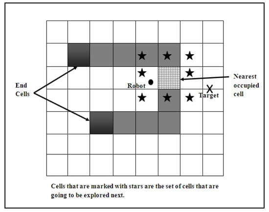
Figure 4.
Define_Deadlock Method.
In each step of exploration, Define_Deadlock takes one cell as the center cell and then explores the eight adjacent cells. If any cell in the adjacent eight is occupied, it is stored in the Deadlock_Enclosure vector and the Exploration Stack. In the next step of exploration, the top cell in the Exploration Stack is popped and set as the center cell, then explored. The method keeps repeating these steps until it reaches the end of the enclosure. In this way, it can define the deadlock enclosure precisely and determine the cells that form it. The algorithm of the local minima detection and definition works as follows: considering the number of navigation steps S, the algorithm of local minima detection and definition has a linear time complexity of O(S) in its worst case, and that is when the robot detects/defines a local minima in every step and when all of the discovered occupied cells are pushed into the stack. After defining the deadlock enclosure, the robot will easily get out of it using the end cells. An end cell is found by counting its surroundings from the vector deadlock enclosure; if the number of surroundings equals 1, then it is an end cell.
- Deadlock Detection {Find Intensity, Adjacency, Threshold, Deadlock ChanceIf (Deadlock Chance > Threshold):Call Define DeadlockActivate “get out of trap”}Define Deadlock{ Find the nearest occupied cell N to the robotCenter <– NStack.Push(Center)Stack.length <– 1Repeat until stack.length=0find adjacent cells coordinatesAdjacent[0]=(Center.x−1,Center.y) // leftAdjacent[1]=(Center.x+1,Center.y) // rightAdjacent[2]=(Center.x−1,Center.y−1) //upper leftAdjacent[3]=(Center.x−1,Center.y+1) //lower leftAdjacent[4]=(Center.x,Center.y−1) //upperAdjacent[5]=(Center.x,Center.y+1) //lowerAdjacent[6]=(Center.x+1,Center.y−1) //upper rightAdjacent[7]=(Center.x+1,Center.y+1) //lower rightFor i = 0 To 7: // adjacent cells indexed from 0 to 7if Adjacent[i] is in OccupiedStack.PUSH (cell i)Stack.LengthStack.Length+1Insert cell i into Deadlock-EnclosureNext iCenter <– stack.POPStack.Length <– Stack.Length-1Loop }
5.3. Addressing the Local Minima
Once the deadlock enclosure is detected and defined, the mode “get out of trap” is activated. In this paper, there are five different approaches proposed to get out of the trap. All of these approaches use the same detection algorithm described in the previous section. Mainly, these approaches depend on two things: 1. Placing a virtual target in appropriate locations instead of the real one to address the target attraction force effect on the robot. 2. Placing virtual obstacles on the deadlock enclosure. This prevents the robot from falling into the same trap after getting out of it.
5.3.1. Random Virtual Target
In this approach, a virtual target point is placed in a random location within a limited area around the farthest end cell from the target. The robot is affected by the new target attraction force and stops seeking the real goal. As a result, the robot starts heading to the virtual goal until it reaches it. Once the robot reaches the virtual goal, the real target point is set back as the target. To avoid the robot being trapped in the same deadlock enclosure again, a virtual obstacle is placed over the whole deadlock enclosure. Closing the deadlock enclosure is performed by calling the Close_Deadlock method. This method first checks whether the robot is still within the area that is to be closed. If so, the virtual obstacle keeps shrinking in a constant ratio until the robot is out of the closed area. The virtual obstacle dimensions are within the coordinates , , , and , which are the smallest x-coordinate, the smallest y-coordinate, the largest x-coordinate, and the largest y-coordinates, respectively, among the coordinates in the Deadlock_Enclosure vector. The random virtual target selection approach is illustrated in Figure 5.
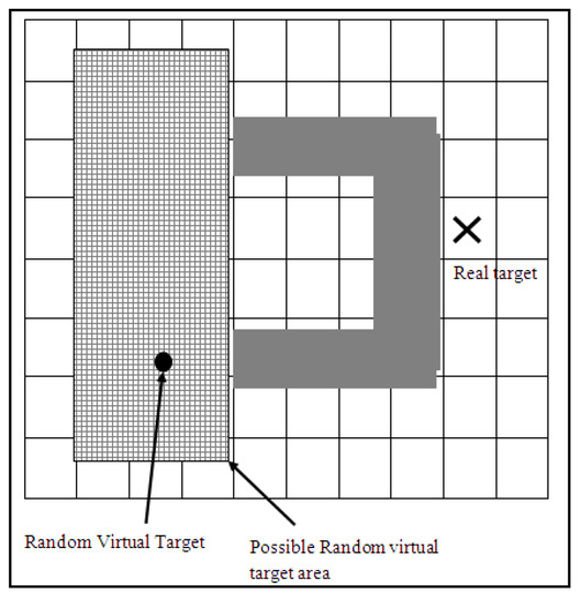
Figure 5.
Random virtual target selection.
To avoid placing the virtual target in a location occupied by an obstacle, the robot first checks whether the selected location for the virtual target is located on an occupied cell using the vector Occupied_Cells. If it is found that an obstacle occupies the selected location, it chooses another random virtual target location.
5.3.2. Reflected Virtual Target
This approach mainly depends on the fact that in most local minima situations, the deadlock enclosure’s opening faces the robot on its way to the target located behind that enclosure. In this case, the problem can be solved by placing a virtual target in front of the obstacle and within the area that precedes the enclosure opening. Once the robot reaches the virtual target, it switches back to the real target and calls the method Close_Deadlock. This can be achieved by simply making a reflection of the real target near the enclosure’s exit. The real target is reflected either horizontally or vertically depending on the enclosure’s exit direction. The appropriate reflection of the real target is achieved by assuming the middle of the enclosure as the reflection axis. This approach is illustrated in Figure 6.
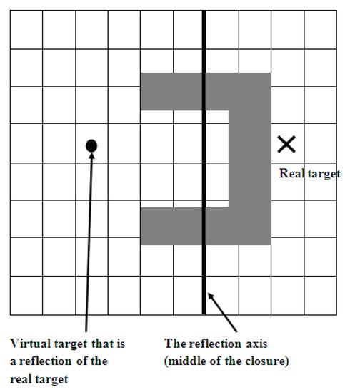
Figure 6.
Virtual target by reflection of the real target.
5.3.3. Backtracking
One way that guarantees the escape from the deadlock enclosure is that the robot follows its steps back to the exit, which is the entrance to the enclosure. Since the visited cells are all stored in the Visited_Cells vector, the robot can easily backtrack its path. To disable the real target’s attraction force, a set of virtual targets are placed on the visited cells that form the backtracking path, starting from the robot’s current location inside the deadlock enclosure and moving backward until a “stop backtracking” point is reached. The sequence of virtual targets is a set of virtual targets placed at every constant number of cells in the Visited_Cells vector. The “stop backtracking” point can be determined using one of three following:
- Global Path Backtracking: The stop point is the same as the start point (S) of the navigation. The robot keeps backtracking until it reaches the starting point. This approach is effective in the case of small environments. However, it is inefficient in wide environments because the robot must reach the very distant starting point when it encounters a deadlock. After the robot escapes from the deadlock, and the mode “get out of trap” is disabled, the start point is re-initialized and set as the first cell the robot traverses after closing that deadlock enclosure.
- Half Path Backtracking: The stop point is the midway point between the current locations of the robot and the starting point. This approach is more effective than the previous one in wide environments but less effective in small environments because the stop point could be inside the enclosure of the deadlock.
- Local Path Backtracking: The stop point is at the end cells. This one could be the most appropriate choice for the point of “stop backtracking” as it guarantees that the robot will not travel so far. On the other hand, it guarantees the robot is out of the deadlock enclosure. The three approaches for choosing the “stop backtracking” point are shown in Figure 7. After the robot reaches the last virtual target in the sequence, a square virtual path of straight lines is set all around the deadlock enclosure. Then, a final virtual target point is set on this path. The virtual path must pass by the real target point and near the last virtual target from the backtracking sequence, as illustrated in Figure 8. The final virtual target is determined as the middle point of the distance between the robot and the real target. In the case that there is not enough space for the virtual path (i.e., not enough space under or above the enclosure for the robot to move), then the final virtual goal is placed on the opposite side of the square virtual path. Final virtual target placed on the virtual path, guaranteeing that the robot moves towards the real target and away from the deadlock.
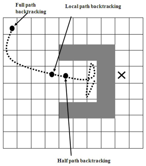 Figure 7. Three approaches to determine the backtracking stop point.
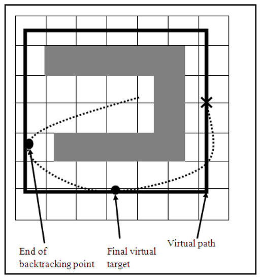 Figure 8. The virtual path in the backtracking method.
5.4. Simulation Results
This section is devoted to reporting on the simulation works conducted in this work. Each of the five proposed approaches was evaluated, and their performance was investigated under different setups. There are four different test cases conducted in this section, including path planning in the presence of C-shaped obstacles, double U-shaped, V-shaped obstacles, and when the robot encounters cluttered environments on its path. The results of each test of the five approaches proposed to address the local minima are then discussed and analyzed.
The unit used to measure the efficiency of the proposed methods to address the local minima is the number of steps the robot makes while traveling from the start point to the target point. The size of a step is constant and equals 10 cm. There are general parameters used in the simulation of the proposed approaches to address the local minima and the fuzzy speed controller. The parameters are summarized in Table 1.

Table 1.
Simulation Parameters.
Local Minima Avoidance
Figure 9 depicts the performance of detecting and identifying the enclosure of a deadlock. The little circles on the cells show whether the cell is occupied or near to another cell that is occupied. This is dependent on the robot’s sensing range; as seen in Figure 9, the above barrier is recognized near the robot, while the below horizontal light green region has yet to be discovered by the robot’s sensors.
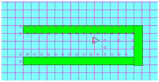
Figure 9.
Deadlock detection and definition performance.
There are four different test cases conducted on the five proposed approaches in addition to the wall-following approach for comparison.
Test case #1: C-shaped obstacle test case
In this test case, the robot is in front of a C-shaped obstacle. Figure 10a–f shows the approach’s performance. The black area represents the visited path by the robot. The challenge in this test case is that the C-shaped obstacle is a circle with a small exit. The performance of the wall-following approach, in Figure 10f, is the worst compared to other proposed approaches. It also required following the whole environment’s perimeter, which is inefficient in large environments. Figure 10a,b shows the superior performance of the reflected target over the random virtual target. This is due to the location of the chosen virtual target. In the reflected virtual target, the virtual target is a reflection of the real target position vertically. The reflected virtual target is near the lower end of the C-shaped obstacle, unlike the random virtual target chosen near the upper end of the obstacle. This added a few extra steps in the random virtual target approach because the only way to reach the target is under the C-shaped obstacle. Figure 10c,e shows the robot’s similar performance, which is because of the similar location of the “stop backtracking” point. In Figure 10d, we noticed the less efficient performance of the robot when it stops backtracking in the middle point of the path; this is because the middle point, in this case, is located inside the C-shaped obstacle. Thus, it required more than one virtual obstacle to close the deadlock enclosure and leave it.
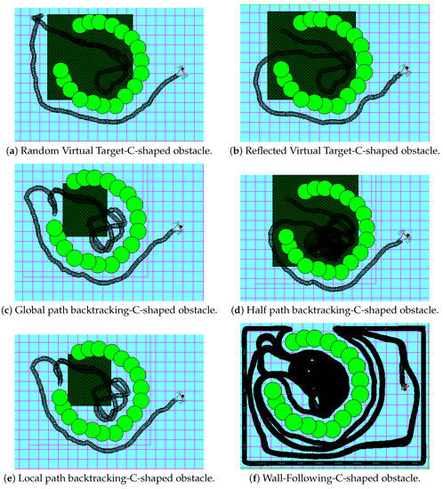
Figure 10.
C-shaped obstacle test case.
Test case #2: Double U-shaped test case
In this test case, the robot enters a trap that is nested in another trap. Figure 11a–f shows the performance of the six approaches. Figure 11a,b shows the advance in performance for the random virtual target approach over the reflected virtual target approach. This can be explained by the way the virtual target is chosen. In the reflected virtual target, the robot finds itself trapped in the inner deadlock, so it places a virtual target that is a horizontal reflection of the real target. This made the virtual target location to be near the inner’s deadlock left end. When the robot switched back to the real target, it was still in the same location as the virtual target; the robot entered the outer deadlock again from the left, then detected that it was trapped again after reaching the right side of the deadlock’s enclosure. After that, it switched back to the real target again, which is the same reflection, but over the middle line of the outer deadlock this time. When the robot switched back to the real target, it was still on the right side while the virtual target was in front of the deadlock but on the left side, which required the robot to go back to the left side again, then go out of the enclosure to the reflected target which adds a few more steps. Unlike this approach, the random choice of the virtual target came once on the left side and once on the right side of the enclosure. As noticed in Figure 11c, the robot stops backtracking when it reaches the starting point. The starting point for the second outer deadlock is the same point where the robot was upon closing the first inner deadlock. Thus, the robot had to reach that point first before closing the outer deadlock, which added a few extra steps for the robot to reach the real target compared to the approaches in Figure 11d,e. In the half path backtracking approach of Figure 11d, the robot stops backtracking when it reaches the middle point of the path, and in Figure 11e, the robot stops backtracking when it reaches the enclosure exit. This is the reason for the similar performance of the local path backtracking and half path backtracking. In Figure 11f, we notice again the inefficient performance of the wall-following method, which caused the robot to traverse the target’s region without seeing it due to the disabling of the goal-seeking action while following the wall. It is important to clarify that the magenta color has been used just to emphasize that the robot does not follow a specific color in Figure 11, and that is also applicable to other figures; Figure 10, Figure 12 and Figure 13.
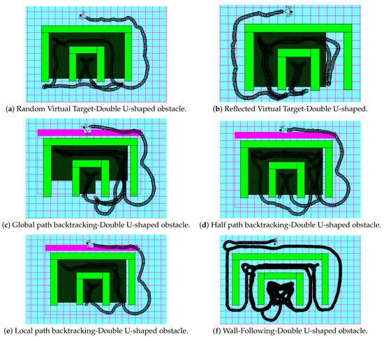
Figure 11.
Double U-shaped test case.
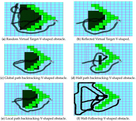
Figure 12.
V-shaped test case.
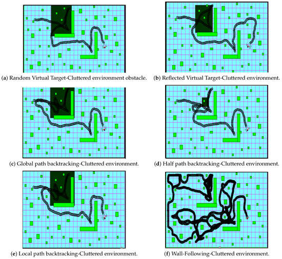
Figure 13.
Cluttered environment test case.
Test case #3: V-shaped test case
In this test case, the robot enters a V-shaped obstacle. Figure 12a–f shows the performance of the six approaches. In Figure 12a, the robot closed most of the enclosure in the first round, but not all of it because the random target at the first round was placed near the end of the enclosure but almost inside. Thus, the robot fell into the same deadlock twice and required two virtual obstacles to close the deadlock region. However, in Figure 12b, we notice a better performance of the reflected target approach because the reflection of the real target is outside the enclosure, which required one round to close the whole deadlock. In Figure 12c,e, we notice a similarity in the performance of the global path and local path backtracking. Because the “stop backtracking” points are almost in the same location (i.e., the robot started navigation from a point near the exit of the deadlock), the performance was different in the half path backtracking approach of Figure 12d. In this test case, this point was inside the V-shaped obstacle; thus, the virtual obstacle shrunk to avoid closing on the robot inside the deadlock. In Figure 12a–e vs. Figure 12f, the wall-following approach took the most significant number of steps, the longest path, to get out of the trap situation because it forced the robot to follow part of the environment’s perimeter wall.
Test case #4: Cluttered environment test case
This is the last test case, and it shows the performance of the six approaches in cluttered and crowded environments. Figure 13a–f shows the results of the test case. In Figure 13a,b, the random target choices, either the random virtual or the reflected virtual targets, show the best performance compared to others. In Figure 13c, we notice the behavior of global path backtracking. The starting point is located a bit far from the deadlock. When the robot needs to get out of the deadlock, it must return to that far point, which is inefficient in such cases. This problem is alleviated in the half path approach, as illustrated in Figure 13d. However, it still adds extra unnecessary steps because the deadlock was not fully covered with the virtual obstacle. This happens when the virtual target is located inside the area that must be covered. So, the virtual obstacle keeps shrinking until the robot is uncovered. The best of the “stop backtracking” points is near the exit of the deadlock enclosure achieved by the local path backtracking approach, and this is clear in Figure 13e. In this test case, Figure 13f shows that the wall-following approach performance performs inefficiently to get to the target. The robot was forced under this approach to circumnavigate around some obstacles (closed shapes) many times, thus wasting a lot of time. Table 2 shows the path length in meters that was taken by the robot working with the six approaches to reach the target point. As noted in the table, the robot with the wall-following approach has the longest path in all of the four tests.

The reflected virtual target shows better performance in test cases 1 and 2, and this is due to its optimal choice for the target location in these test cases. As noted in the table, the test case that required the longest path in all six approaches is the test case of the double U-shaped obstacle.
The chart in Figure 14 shows the performance of the five approaches compared to the wall-following approach. The efficiency of the six approaches is measured in the number of steps required for the robot to reach the final real target. One important point to be mentioned in this section is that each experiment was conducted 10 times to mitigate the effect of randomization. The results recorded in this section are an average of ten runs.
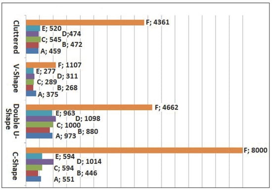
Figure 14.
Performance of the proposed approaches to overcome the local minima compared to the wall-following approach (measured by the number of steps).
5.5. Speed Control Effect on the Five Proposed Approaches to Address the Local Minima
This section reports on the studies conducted to determine the effect of controlling the speed using the previously proposed fuzzy controller [8] on the performance of the proposed approaches. To address the local minima problem, the mobile robot of fuzzy speed was provided with these approaches and then tested using the same four environmental setups by replicating the same encountered local minima. Table 3 shows the efficiency performance of the five proposed approaches to address the local minima with constant speed within the four environments. Table 4 shows the performance of the five proposed approaches with a fuzzy-speed robot. The performance of the proposed approaches is measured by the time (in seconds) elapsed between the start and the end of navigation. It shows the wall-following approach consumes the longest time in the trips. The local path backtracking approach seems to be the best choice for leaving the deadlock enclosure in general due to its reasonability in choosing the right point to stop backtracking. On the other hand, half path backtracking seems to be the least suitable approach when the robot starts navigating from a location that is close to the deadlock enclosure, unlike global path planning, which is suitable for short paths but not for long ones.

Table 3.
Time spent during navigation by the five proposed approaches to address the local minima with a constant-speed robot (seconds).

Table 4.
Time spent during navigation by the five proposed approaches to address the local minima with a fuzzy-speed robot [2] (measured in seconds).
For the U-shaped, W-shaped, and E-shaped obstacles, the best approach that can be used to take the robot out of the deadlock enclosure is the local path backtracking. For the double U-shaped and V-shaped obstacles, the best choice is to use the reflected virtual target approach, especially if the target is located right behind the deadlock enclosure and the robot in front of it. The random virtual target approach is the most suitable approach for complex environments, such as cluttered environments.
When the robot moves under the proposed fuzzy speed control, the time needed to reach the target is decreased in general, although there are some odd cases, such as the majority of the approaches’ performance in the E-shaped obstacle test and in the double U-shaped obstacle test. Moreover, the wall following approach with fuzzy speed is noted to be much slower, especially in the cluttered environment test and in the V-shaped test. This slower speed for the robot with fuzzy speed control is referred to for one or more of the following reasons: Most trap enclosures force the robot to keep moving with a high rate of rotations and wide heading angles, specifically before detecting the local minima. This reduces the speed of the robot because the heading angle is a strong factor that controls the speed in the proposed fuzzy speed controller. The difference in speed rates of the robot can be observed in Figure 15, where thick and dark paths mean a low speed. The path in the figure indicates the locations of the steps taken by the robot. The robot’s behavior is not the same when the speed is controlled, and that is because the step length chosen by the fuzzy system varies from one step to another. As an example, let us consider a robot with a constant step length. The robot in step S at location L1 measures the distance between itself and the nearest obstacle, say D1. Depending on the value of D1, the robot determines the next step’s heading angle as in the proposed original navigation system [9]. On the other hand, if the speed is controlled, the same step S will navigate the robot to another location L2, because the step length is different. In this case, the robot measures a different distance D2 to the nearest obstacle. As a result, the robot’s decision of the heading angle will also be different. This variance in behavior improved the performance, on average, of the reflected virtual target approach over the local path backtracking approach in general.
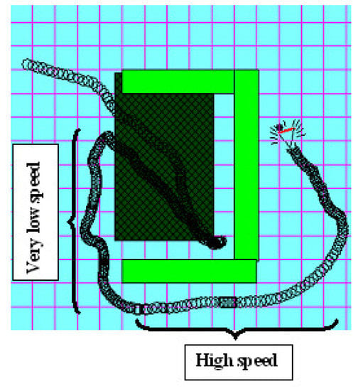
Figure 15.
The difference in speed rates when the speed is controlled by the proposed fuzzy speed controller.
In the wall-following approach, the robot is much slower because it keeps moving along with the obstacles’ walls. This means that during the wall-following behavior, the robot is very near to obstacles, which also reduces its speed dramatically, as noted in Figure 16.
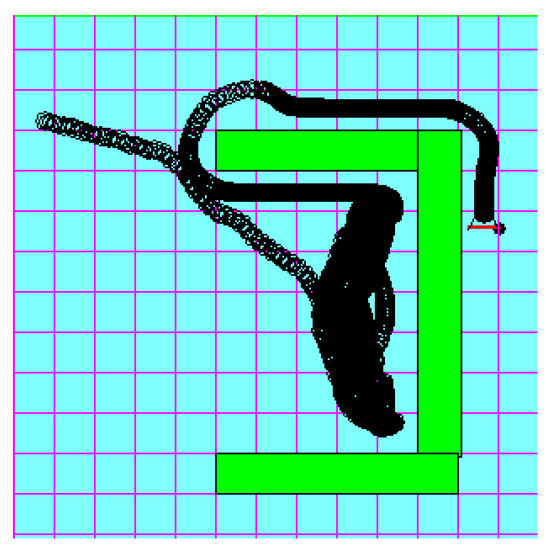
Figure 16.
Wall-following approach reaches very low-speed rates when the robot follows the walls.
In environments that include local minima situations, most of the robot steps are either inside the deadlock enclosure or outside but very close. This means that the factor should be higher in these environments, and the speed should be much lower. The wall-following approach’s performance was significantly improved when the speed was controlled with the proposed fuzzy system for the E-shaped, C-shaped, double U-shaped, and W-shaped obstacles test cases. This is because, in these test cases, the robot did not follow the whole environment perimeter’s wall, as shown in Figure 17 when set side by side with Figure 9f.
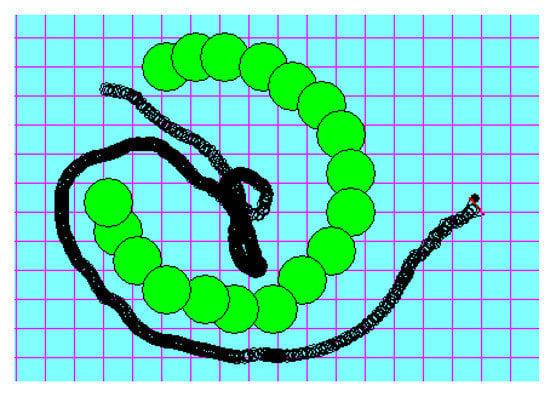
Figure 17.
Wall-following performance in the C-shaped obstacle test case.
6. Conclusions and Future Work
6.1. Limitations and Future Work
When the opportunities offered by IoT technologies are exploited fully in an industrial setup, this creates a rich and ubiquitous environment. IoT devices mounted on various objects ranging from vehicles, humans, robots, goods, to moving and still objects all contribute with data that would transform a typical warehouse setting into a well-connected and dynamic smart space. As such, when robot’s path planning algorithms are empowered by the data contributed by IoT devices, the IoT system, such as the location of objects, presence of obstacles, and the dynamic changes in the environment, enormous opportunities and improvement to path planning and obstacle avoidance, will arise. The solutions proposed in this work enhance robots’ navigation in device-to-device decentralized setups. While the results were verified using simulation work, performance results in real-world experimental scenarios remain to be validated. Future work is planned to enable the full extent of IoT incorporation into the robots’ navigational systems. The plan is to set up a number of IoT-enabled robots in a shared environment with other IoT devices and obstacles. We will then attempt to further optimize the proposed solution and make better use of the data supplied by the IoT system. In addition, the local minima problem can be addressed using more than one robot with deep learning solutions, especially in real-life domain space. Robotic co-workers may present and work collaboratively with their peers (human workers) concurrently. Having more robots in a smart factory space could earnestly require a robust system to handle the unpredicted movement of multiple robots in a closed area, such as in a factory.
6.2. Conclusions
In robot navigation systems in IoT, there are main goals that must be achieved, including seeking the goal, avoiding obstacles, and avoiding local minima. In this work, five approaches to address the local minima problem are proposed. Their implications and opportunities in the context of IoT and Industry 5.0 were also highlighted. The reliability of the five proposed approaches and the achieved enhancement in performance was validated by comparing the five approaches to the popular wall-following approach. The results show a significant advantage and improvement in performance in the four test cases conducted in this work. A significant improvement in performance was reported specifically in the cases where the robot encountered W-shaped, C-shaped, and double U-shaped obstacles. Additionally, in cluttered environments, the proposed approaches minimized the distance and time required by the robot to reach its destination by eight times when compared to the traditional path planning approaches. Overall, the results showed that the robot using any of the five proposed approaches requires fewer steps to reach the destination, ranging from 59 to 73 m on average across varied obstacle forms, as opposed to the wall-following strategy, which requires an average of 732 m. On average, the robot with a constant speed and reflected virtual target approach takes 103 s to complete the tasks, which is the greatest performance among the other approaches, whereas the identical robot with a wall-following approach takes 907 s. Using a fuzzy-speed robot, the duration for the wall-following approach is greatly reduced, from 907 to 507 s, while the reflected virtual target, random target, and global path backtracking may only need up to 20%t of that time; 94, 96, and 97 s, respectively. This can be attributed to the fact that the robot using the wall-following approach keeps moving along with the obstacles’ walls in order to avoid the local minima.
Author Contributions
Conceptualization, Y.T. and I.H.-M.; methodology, Y.T., I.H.-M., B.A., and O.D.; software, Y.T., I.H.-M., and M.M.; validation, Y.T., O.D., B.A., and M.M.; formal analysis, I.H.-M., B.A., O.D., and M.M.; investigation, Y.T., I.H.-M., and M.E.; resources, Y.T., O.D., M.M., B.A., and N.A.; data curation, Y.T. and I.H.-M.; writing—original draft preparation, Y.T., I.H.-M., B.A., O.D., and M.M.; writing—review and editing, B.A., O.D., M.M., M.E., and N.A.; visualization, Y.T., I.H.-M., B.A., O.D., and M.M.; supervision, Y.T.; project administration, O.D., M.M., and B.A. All authors have read and agreed to the published version of the manuscript.
Funding
This research received no external funding.
Data Availability Statement
Authors can confirm that all relevant data are included in the article.
Conflicts of Interest
The authors declare no conflict of interest.
References
- Harapanahalli, S.; Mahony, N.O.; Hernandez, G.V.; Campbell, S.; Riordan, D.; Walsh, J. Autonomous Navigation of mobile robots in factory environment. Procedia Manuf. 2019, 38, 1524–1531. [Google Scholar] [CrossRef]
- Nahavandi, S. Industry 5.0—A Human-Centric Solution. Sustainability 2019, 11, 4371. [Google Scholar] [CrossRef] [Green Version]
- Kaiser, M.S.; Al Mamun, S.; Mahmud, M.; Tania, M.H. Healthcare Robots to Combat COVID-19. In COVID-19: Prediction, Decision-Making, and its Impacts; Santosh, K., Joshi, A., Eds.; Springer: Singapore, 2021; pp. 83–97. [Google Scholar] [CrossRef]
- Fang, B.; Guo, X.; Wang, Z.; Li, Y.; Elhoseny, M.; Yuan, X. Collaborative task assignment of interconnected, affective robots towards autonomous healthcare assistant. Future Gener. Comput. Syst. 2019, 92, 241–251. [Google Scholar] [CrossRef]
- Farid, F.; Elkhodr, M.; Sabrina, F.; Ahamed, F.; Gide, E. A smart biometric identity management framework for personalised IoT and cloud computing-based healthcare services. Sensors 2021, 21, 552. [Google Scholar] [CrossRef]
- Demirhan, M.; Premachandra, C. Development of an Automated Camera-Based Drone Landing System. IEEE Access 2020, 8, 202111–202121. [Google Scholar] [CrossRef]
- Premachandra, C.; Tamaki, M. A Hybrid Camera System for High-Resolutionization of Target Objects in Omnidirectional Images. IEEE Sens. J. 2021, 21, 10752–10760. [Google Scholar] [CrossRef]
- Tashtoush, Y.; Haj-Mahmoud, I. Fuzzy Speed Controller for Mobile Robots Navigation in Unknown Static Environments. In Proceedings of the International Conference on Digital Information Processing, Beijing, China, 21–22 April 2013; p. 139. [Google Scholar]
- Al-Jarrah, O.M.; Tashtoush, Y.M. Mobile robot navigation using fuzzy logic. Intell. Autom. Soft Comput. 2007, 13, 211–228. [Google Scholar] [CrossRef]
- Boldrer, M.; Andreetto, M.; Divan, S.; Palopoli, L.; Fontanelli, D. Socially-Aware Reactive Obstacle Avoidance Strategy Based on Limit Cycle. IEEE Robot. Autom. Lett. 2020, 5, 3251–3258. [Google Scholar] [CrossRef]
- Grover, J.S.; Liu, C.; Sycara, K. Deadlock Analysis and Resolution for Multi-Robot Systems. In Proceedings of the International Workshop on the Algorithmic Foundations of Robotics XIV; Springer International Publishing: Berlin/Heidelberg, Germany, 2021; pp. 294–312. [Google Scholar]
- Mohanty, P.K.; Kodapurath, A.A.; Singh, R.K. A Hybrid Artificial Immune System for Mobile Robot Navigation in Unknown Environments. Iran. J. Sci. Technol. Trans. Electr. Eng. 2020, 44, 1619–1631. [Google Scholar] [CrossRef]
- Wahab, M.N.A.; Nefti-Meziani, S.; Atyabi, A. A comparative review on mobile robot path planning: Classical or meta-heuristic methods? Annu. Rev. Control 2020, 50, 233–252. [Google Scholar] [CrossRef]
- Abiyev, R.; Ibrahim, D.; Erin, B. Navigation of mobile robots in the presence of obstacles. Adv. Eng. Softw. 2010, 41, 1179–1186. [Google Scholar] [CrossRef]
- Xie, Y.; Zhang, X.; Meng, W.; Zheng, S.; Jiang, L.; Meng, J.; Wang, S. Coupled fractional-order sliding mode control and obstacle avoidance of a four-wheeled steerable mobile robot. ISA Trans. 2021, 108, 282–294. [Google Scholar] [CrossRef] [PubMed]
- Cuevas, F.; Castillo, O.; Cortés-Antonio, P. Omnidirectional four wheel mobile robot control with a type-2 fuzzy logic behavior-based strategy. In Intuitionistic and Type-2 Fuzzy Logic Enhancements in Neural and Optimization Algorithms: Theory and Applications; Springer: Berlin/Heidelberg, Germany, 2020; pp. 49–62. [Google Scholar]
- Zhu, A.; Yang, S.X. Neurofuzzy-Based Approach to Mobile Robot Navigation in Unknown Environments. IEEE Trans. Syst. Man Cybern. Part C (Appl. Rev.) 2007, 37, 610–621. [Google Scholar] [CrossRef]
- Back, S.; Cho, G.; Oh, J.; Tran, X.T.; Oh, H. Autonomous UAV Trail Navigation with Obstacle Avoidance Using Deep Neural Networks. J. Intell. Robot. Syst. 2020, 100, 1195–1211. [Google Scholar] [CrossRef]
- Ben Jabeur, C.; Seddik, H. Design of a PID optimized neural networks and PD fuzzy logic controllers for a two-wheeled mobile robot. Asian J. Control 2021, 23, 23–41. [Google Scholar] [CrossRef]
- Yang, S.; Li, T.; Shi, Q.; Bai, W.; Wu, Y. Artificial Potential-Based Formation Control with Collision and Obstacle Avoidance for Second-order Multi-Agent Systems. In Proceedings of the 2020 7th International Conference on Information, Cybernetics, and Computational Social Systems (ICCSS), Guangzhou, China, 13–15 November 2020; IEEE: Guangzhou, China, 2020; pp. 58–63. [Google Scholar] [CrossRef]
- Receveur, J.B.; Victor, S.; Melchior, P. Autonomous car decision making and trajectory tracking based on genetic algorithms and fractional potential fields. Intell. Serv. Robot. 2020, 13, 315–330. [Google Scholar] [CrossRef]
- Li, C.; Cui, G.; Lu, H. The design of an obstacle avoiding trajectory in unknown environment using potential fields. In Proceedings of the 2010 IEEE International Conference on Information and Automation, Harbin, China, 20–23 June 2010; pp. 2050–2054. [Google Scholar]
- Csiszar, A.; Drust, M.; Dietz, T.; Verl, A.; Brisan, C. Dynamic and interactive path planning and collision avoidance for an industrial robot using artificial potential field based method. In Mechatronics; Springer: Berlin/Heidelberg, Germany, 2011; pp. 413–421. [Google Scholar]
- Li, G.; Tamura, Y.; Yamashita, A.; Asama, H. Effective improved artificial potential field-based regression search method for autonomous mobile robot path planning. Int. J. Mechatron. Autom. 2013, 3, 141. [Google Scholar] [CrossRef] [Green Version]
- Javaid, M.; Haleem, A.; Singh, R.P.; Suman, R. Substantial Capabilities of Robotics in Enhancing Industry 4.0 implementation. Cogn. Robot. 2021, 1, 58–75. [Google Scholar] [CrossRef]
- Barosz, P.; Gołda, G.; Kampa, A. Efficiency Analysis of Manufacturing Line with Industrial Robots and Human Operators. Appl. Sci. 2020, 10, 2862. [Google Scholar] [CrossRef] [Green Version]
- Carrasco, P.; Cuesta, F.; Caballero, R.; Perez-Grau, F.J.; Viguria, A. Multi-Sensor Fusion for Aerial Robots in Industrial GNSS-Denied Environments. Appl. Sci. 2021, 11, 3921. [Google Scholar] [CrossRef]
- Rogowski, A.; Skrobek, P. Object Identification for Task-Oriented Communication with Industrial Robots. Sensors 2020, 20, 1773. [Google Scholar] [CrossRef] [PubMed] [Green Version]
- Le, A.V.; Nhan, N.H.K.; Mohan, R.E. Evolutionary Algorithm-Based Complete Coverage Path Planning for Tetriamond Tiling Robots. Sensors 2020, 20, 445. [Google Scholar] [CrossRef] [PubMed] [Green Version]
- Krishna, K.M.; Kalra, P.K. Solving the local minima problem for a mobile robot by classification of spatio-temporal sensory sequences. J. Robot. Syst. 2000, 17, 549–564. [Google Scholar] [CrossRef]
- Nurmaini, S. Intelligent navigation in unstructured environment by using memory-based reasoning in embedded mobile robot. Eur. J. Sci. Res. 2012, 72, 228–244. [Google Scholar]
- Ordonez, C.; Collins, E.G.; Selekwa, M.F.; Dunlap, D.D. The virtual wall approach to limit cycle avoidance for unmanned ground vehicles. Robot. Auton. Syst. 2008, 56, 645–657. [Google Scholar] [CrossRef]
- Um, D.; Ryu, D.; Kang, S. A framework for unknown environment manipulator motion planning via model based realtime rehearsal. In Intelligent Autonomous Systems 12; Springer: Berlin/Heidelberg, Germany, 2013; pp. 623–631. [Google Scholar]
- Taylor, K.; LaValle, S.M. I-Bug: An intensity-based bug algorithm. In Proceedings of the 2009 IEEE International Conference on Robotics and Automation, Kobe, Japan, 12–17 May 2009; pp. 3981–3986. [Google Scholar]
- Lumelsky, V.; Stepanov, A. Dynamic path planning for a mobile automaton with limited information on the environment. IEEE Trans. Autom. Control 1986, 31, 1058–1063. [Google Scholar] [CrossRef]
- Sanchez, G.M.; Giovanini, L.L. Autonomous navigation with deadlock detection and avoidance. In Sociedad Iberoamericana de Inteligencia Artificial; CONICET: Buenos Aires, Argentina, 2014. [Google Scholar]
Publisher’s Note: MDPI stays neutral with regard to jurisdictional claims in published maps and institutional affiliations. |
© 2021 by the authors. Licensee MDPI, Basel, Switzerland. This article is an open access article distributed under the terms and conditions of the Creative Commons Attribution (CC BY) license (https://creativecommons.org/licenses/by/4.0/).
