Smartphone-Based Indoor Integrated WiFi/MEMS Positioning Algorithm in a Multi-Floor Environment
Abstract
: Indoor positioning in a multi-floor environment by using a smartphone is considered in this paper. The positioning accuracy and robustness of WiFi fingerprinting-based positioning are limited due to the unexpected variation of WiFi measurements between floors. On this basis, we propose a novel smartphone-based integrated WiFi/MEMS positioning algorithm based on the robust extended Kalman filter (EKF). The proposed algorithm first relies on the gait detection approach and quaternion algorithm to estimate the velocity and heading angles of the target. Second, the velocity and heading angles, together with the results of WiFi fingerprinting-based positioning, are considered as the input of the robust EKF for the sake of conducting two-dimensional (2D) positioning. Third, the proposed algorithm calculates the height of the target by using the real-time recorded barometer and geographic data. Finally, the experimental results show that the proposed algorithm achieves the positioning accuracy with root mean square errors (RMSEs) less than 1 m in an actual multi-floor environment.1. Introduction
In the recent decade, next generation techniques, indoor positioning and navigation have gained significant attention, since the signals from the widely-used global navigation satellite systems are often not hearable inside buildings. Furthermore, the indoor positioning and navigation approaches generally require higher accuracy and better adaptation to the environment compared to outdoor ones. Under such a circumstance, a number of positioning techniques have been studied and even used in many special scenarios, like Bluetooth, ultra-wide band (UWB), radio frequency identification (RFID) and WiFi fingerprinting-based positioning techniques [1–4].
As far as we know, the WiFi fingerprinting-based positioning technique has been much favored in the indoor and underground environments, due to the low device cost, wide infrastructure deployment and high positioning accuracy [5–9]. However, the signal refraction, reflection, scattering and multi-path fading generally result in the low reliability of the received signal strength indicator (RSSI) measurements and, thereby, deteriorate the accuracy of fingerprinting-based positioning. To solve this problem, some previous positioning techniques by integrating WiFi fingerprinting and MEMS sensors are proposed in [10–14].
Since most of the current mobile devices are integrated with various sensors, like the inertial sensors, magnetometer and barometer, MEMS sensor-based positioning is becoming a popular relative and self-contained positioning technique. In generally, the MEMS sensor-based positioning features the advantages of low device cost, short-term accurate positioning results and independence of external noise [15–19]. However, the associated accumulative error involved in MEMS sensor-based positioning is always considered one of the significant problems.
The three main contributions of this paper are summarized as follows. First of all, we rely on the gait detection approach instead of conducting acceleration integration to optimize the velocity calculation, as well as using the quaternion algorithm to improve the precision of the heading angle calculation. Second, we design a robust extended Kalman filer (EKF) by using the robust least squares estimation to reduce the accumulated errors involved in MEMS sensor-based positioning, as well as the large errors of WiFi fingerprinting-based positioning. Finally, to achieve three-dimensional (3D) positioning in a multi-floor environment, the floor height calculation algorithm is proposed.
The rest of this paper is organized as follows. Section 2 gives some related work on WiFi fingerprinting-based positioning systems, as well as the existing indoor WiFi/MEMS positioning systems. Section 3 presents the proposed integrated WiFi/MEMS positioning algorithm, as well as the height calculation approach. The experimental results by using the data from WiFi fingerprinting and MEMS sensors in an actual multi-floor environment are provided in Section 4. Finally, we conclude this paper in Section 5.
2. Related Works
As the most representative fingerprinting-based positioning systems, a RADAR system [4] relies on the K nearest neighbor (KNN) algorithm to infer the 2D locations of a static target in a building. However, the accuracy of motion tracking by using the RADAR system cannot be guaranteed, since only a small number of RSSI measurements are recorded at each fixed location.
To solve this problem, the authors in [9] proposed to use the Kalman Filter (KF) to improve the accuracy of motion tracking. One of the serious disadvantages of the approach in [9] is that the velocity of the target is assumed to be a fixed value adding a small Gaussian random variable. Thus, the tracking errors could be significantly large when the actual velocity of the target varies significantly. Furthermore, to estimate the velocity of the target in a real-time manner, the authors in [10] invented an integrated WiFi fingerprinting and inertial sensing-based positioning system in which the acceleration data of the target are record by a tri-axis accelerometer. However, the velocity of the target would not be accurate by using the Newton uniformly accelerated linear kinematic equations, since the MEMS sensors of smartphones are low precision and with a low output frequency. As a consequence, the accumulative error increases rapidly in a short time.
By considering the variations of WiFi RSSI measurements with respect to the physical locations, the authors in [11] proposed utilizing the signal propagation property to conduct localization. However, a precise signal propagation model in the indoor environment is always difficult to obtain. By taking the fluctuation of WiFi RSSI measurements and the output data of the accelerometer into consideration, a WiFi/magnetic, angular rate and gravity (MARG)-based positioning algorithm by using particle filtering (PF) is proposed in [12]; this algorithm can only be applied to 2D positioning, and the associated precision is insufficient.
To achieve 3D positioning, the K-means-based algorithm in [20] is selected to identify the floor on which the target is located. The performance of height estimation deteriorates seriously when the target is inside a staircase. In this paper, we first rely on the gait detection approach to reduce the errors of velocity estimation, as well as use the quaternion algorithm to improve the heading precision. Second, we design a robust EKF filter by using the robust least squares estimation to resist the errors involved in both MEMS-based sensing and WiFi fingerprinting-based positioning. Finally, we use the floor height calculation algorithm to achieve 3D positioning in a multi-floor environment.
3. System Description
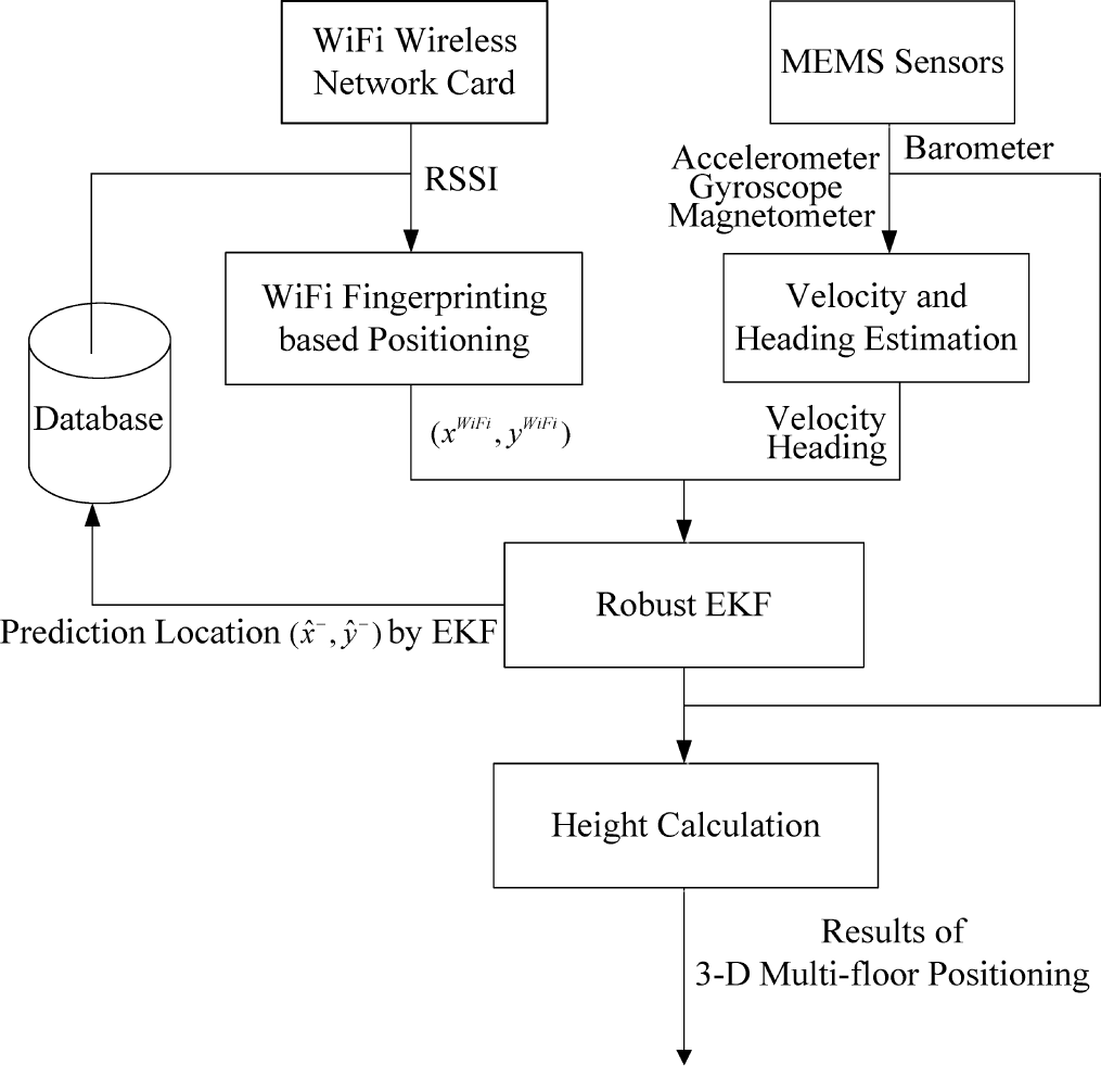
The flow chart of the proposed indoor integrated WiFi/MEMS positioning algorithm is shown in Figure 1. There are four main modules contained in this system, namely WiFi fingerprinting-based positioning, velocity and heading estimation, robust EKF and height calculation modules.
The velocity and heading data obtained from the MEMS sensors, v and φ, together with the results of WiFi fingerprinting-based positioning are set as the input data of the robust EKF. The output data of the robust EKF is the estimated 2D coordinates of the target. After that, we integrate this estimated 2D coordinates and the height, which is calculated from the height calculation module, to output the estimated 3D coordinates of the target.
3.1. WiFi Fingerprinting-Based Positioning
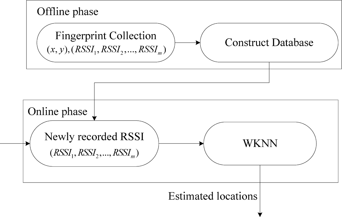
In our system, the WiFi fingerprinting-based positioning involves two phases, the offline phase and online phase, as described in Figure 2.
In the offline phase, the RSSI measurements from all of the hearable access points (APs) at each reference point (RP) are recorded as the fingerprints, and the fingerprints and their corresponding Cartesian coordinates are then used to construct the fingerprint database. In the online phase, the newly recorded RSSI measurements are matched against the pre-constructed fingerprint database to obtain the estimated locations of the target.
In the indoor environment, there could be large positioning errors when RSSI measurements with significant fluctuation are used for positioning. To solve this problem, we rely on the predicted EKF state to smooth the WiFi RSSI fluctuation. Specifically, we select K (K > 1) RPs’ RSSI vectors recorded in the database with the minimal physical distances from the predicted EKF state. Then, we use these RPs’ RSSI vectors to calculate the predicted RSSI vector.
3.2. Velocity and Heading Estimation
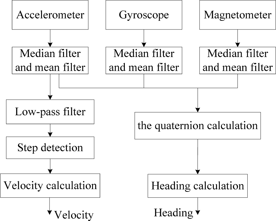
We rely on the three-axis accelerometer, three-axis gyroscope and three-axis magnetometer in a smartphone to estimate the velocity and heading angles of the target. As can be seen from Figure 3, we first eliminate the device noise, as well as smooth the waveform with the help of a median filter and a mean filter, respectively. After that, we estimate the velocity based on the triaxial accelerometer data and, meanwhile, the heading angles by using the quaternion algorithm.
3.2.1. Velocity Estimation
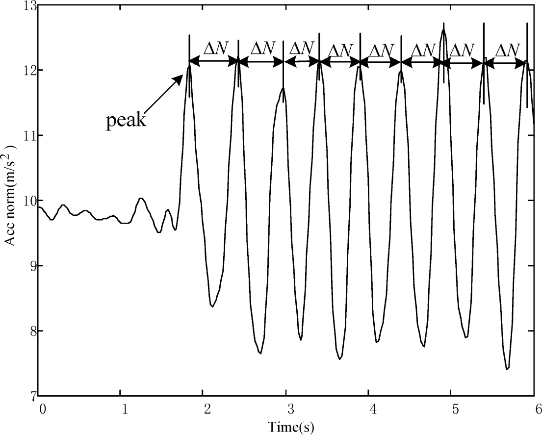
Based on the physiological characteristics of people, the waveform of the three-axis accelerometer modulus values describes the cyclical changes. The cyclical changes can be then used to detect the steps of people. In concrete terms, we calculate the three-axis accelerometer modulus values in Equation (3):
Since the frequency of the output data from MEMS sensors is fs, the time interval during the k-th step is calculated as:
For simplicity, by assuming that the velocity of the target during each step is a constant, the velocity for the k-th step is calculated by:
3.2.2. Heading Estimation
In this paper, we use the quaternion algorithm to estimate the heading angles of the target. The quaternion algorithm features the advantages of low computation cost and wide applications.
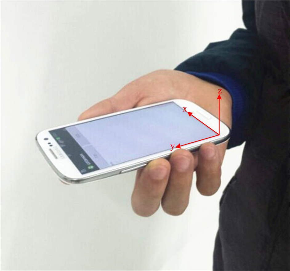
As shown in Figure 5, we define a local smartphone x-y-z frame with respect to the mobile platform, as well as a reference coordinate frame in which the E-axis points east, the N-axis points north and the U-axis points upwards with respect to the horizon ground. The attitude rotation matrix depicts the relationship of the coordinates in the reference coordinate frame and in the local smartphone x-y-z frame, such that:
In Equation (7), the attitude rotation matrix is determined when the quaternion, q, is obtained. Based on the vector differential equation in rigid body angular motion, we have:
We use Equation (7) to update the attitude rotation matrix when the solutions of Equations (10) and (11) have been obtained. In this case, the heading angles can be estimated by using the attitude rotation matrix.
In practical applications, the low-cost gyroscope in a smartphone is not ideal. Thus, the heading angles could involve accumulated errors due to the gyroscope drift. Therefore, the integration of the gyroscope, accelerometer and magnetometer for the sake of calculating the attitude angles can effectively improve the heading precision. To achieve this goal, the EKF model is considered in this paper to integrate all of the sensing information to obtain the accurate estimation of the heading angles. The EKF model is described as:
Finally, by using the EKF model to update the quaternion, we calculate the heading angles in Equation (15).
3.3. Robust EKF
3.3.1. EKF Model
The locations of people depend on the walking velocity and heading. On this basis, we set the state vector , which consists of the locations of the people (x, y), the velocity v and the heading φ. The EKF model is shown in Equation (16).
The measurement vector consists of the locations estimated by WiFi fingerprinting-based positioning (xWiFi, yWiFi) and the velocity and heading data obtained from MEMS sensors, vMEMS and φMEMS.
3.3.2. Robust Least Squares Estimation
Based on the robust least squares estimation, we distribute smaller weights to the measurement vector, , which correspond to the residuals larger than the standard deviation of the measurements. By using the IGG3 weight function [22], the weights of measurements are calculated by:
Finally, the prediction and updating process of the robust EKF is described as follows.
Prediction process:
Updating process:
where is the Jacobian matrix. is the gain of the robust EKF. Pn is the error covariance matrix. Hn is the measurement sensitivity matrix. I is a unit matrix. is the equivalent weight matrix. .
3.4. Height Calculation
3.4.1. Altitude Estimation
The altitude is estimated based on the characteristic that the atmospheric pressure measured by the barometer decreases as the altitude increases [23,24]. The process of altitude calculation is described as follows.
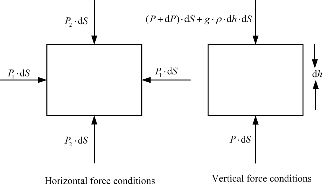
When the force balance is preserved, the air is in a stationary condition, as shown in Figure 6.
In Figure 6, the static atmosphere equation in the vertical force condition is described by:
By conducting the integration calculation on both sides of (23), one has:
Based on Equations (25) and (26), the geopotential height, h, is calculated by:
3.4.2. Multi-Floor Positioning
In the staircase scenario, the accuracy of the WiFi-based height calculation deteriorates seriously. Furthermore, there is no significant impact on accuracy by adding the height into the state vector in the condition that the target is on a floor. On this basis, the height is calculated separately in our system.
The motion behaviors of the people inside a building can be simply classified into two categories, walking up or down stairs in staircases and walking on a floor. Figure 7 shows the flow chart of height calculation. In our experiments, the step lengths of the people with respect to the motion behaviors in a staircase and on a floor are set to be 0.4 m and 0.68 m, respectively.
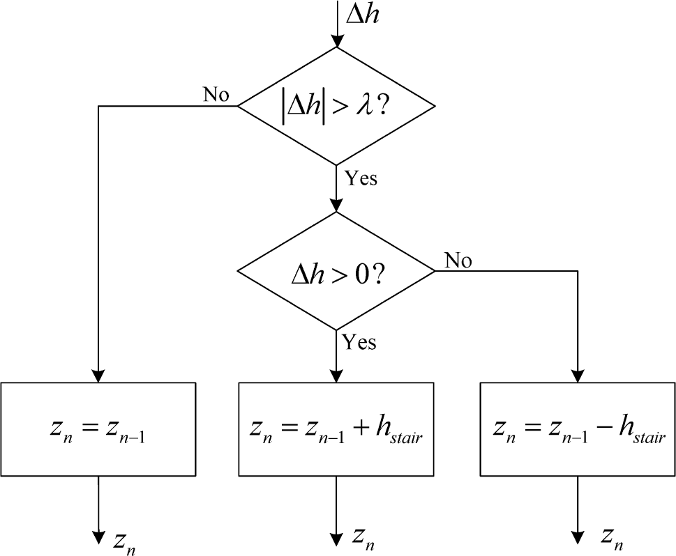
When the target is located in a staircase, we first use Equation (25) to estimate the altitude of the target, h1. Second, we calculate the height of the target based on the distance between h1 and the altitude of the entrance of staircase h2, Δh = h1 − h2, as shown in Figure 8.
In Figure 8, by setting a threshold λ, if |Δh| ≤ λ, we set the height of the target in the current step as equal to the height of the target in the previous step. If |Δh| > λ and Δh > 0, we set the height of the target in the current step as the previous height, adding a stair height hstair. Otherwise, we set the height of the target in the current step as the previous height, subtracting hstair.
When the target is located on a floor, we set the height of the target equal to the current floor height.
Furthermore, the steps of the judgment of whether the n-th location of the target is in a staircase or on a floor are as follows.
Calculate the distance between the n − 1-th locations of the target , and and the location of the entrance of the i-th staircase (xi, yi, zi), di,n−1.
Compare the values of di,n−1 and r, where r is a given threshold.
When di,n−1 ≥ r and the n-th locations of the target are in the same staircase or on the same floor.
When di,n−1 < r if the n − 1-th location of the target is in a staircase, the n location of the target is on a floor. To the contrary, if the n − 1-th location of the target is on a floor, the n-th location of the target is in a staircase.
4. Experimental Results
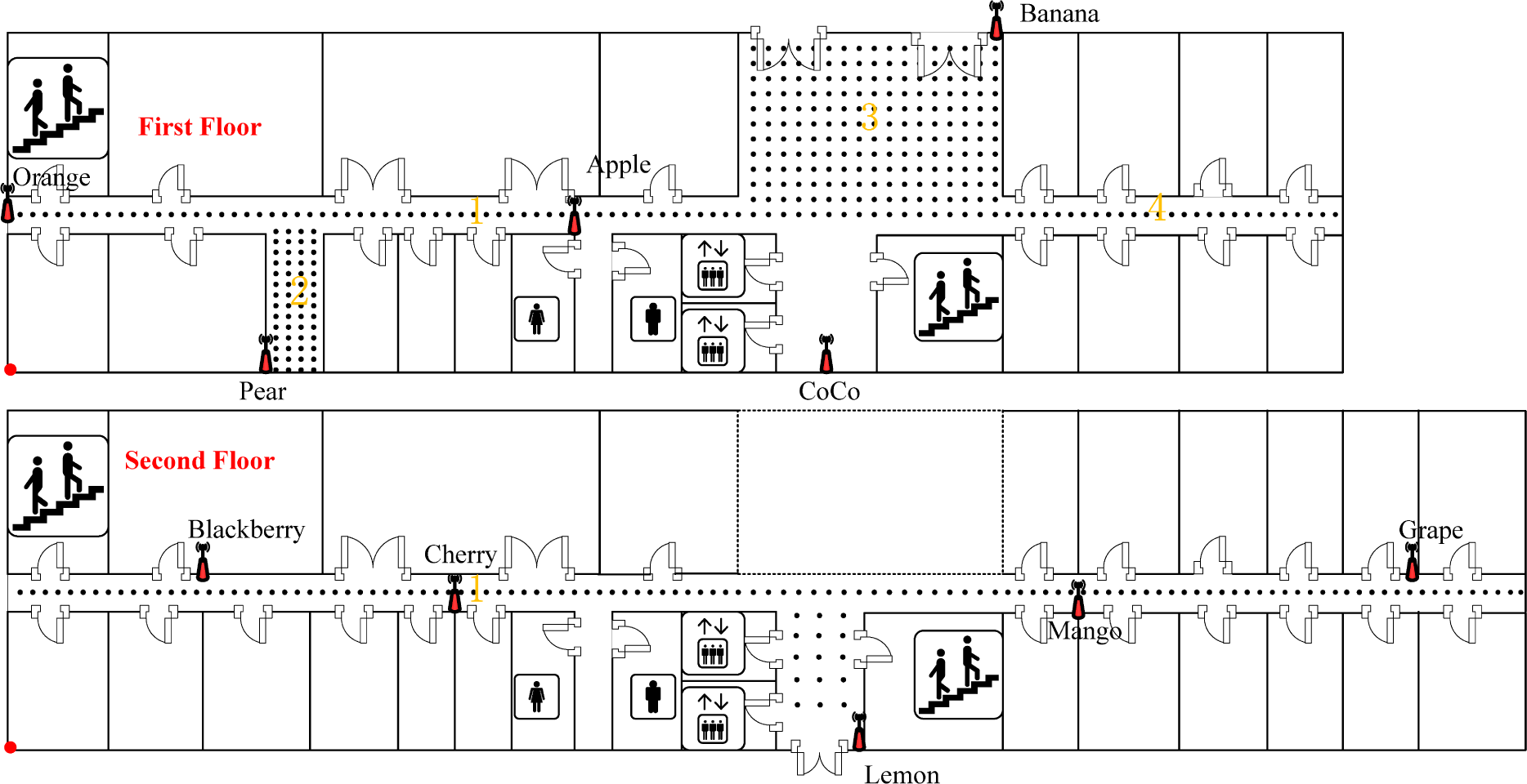
The testbed is selected on the first and second floors in a building at a university. These first and second floors have different dimensions of 64.6 × 18.5 m2 and 81.2 × 18.5 m2, respectively, as shown in Figure 9. There are 10 D-Link DAP 2310 APs (marked in red) deployed in this environment, named orange, pear, apple, banana, coco, blackberry, cherry, lemon, mango and grape, respectively. The RPs are uniformly calibrated with an interval of 0.6 m.
In our experiments, a Samsung Galaxy S3 smartphone, which is integrated with a WiFi module, accelerometer, gyroscope, magnetometer and barometer, is selected as the receiver. We invented two apps, WifiSensors and WifiLocation, to conduct MEMS sensors and WiFi RSSI recording. The recorded data are saved in the security digital (SD) card with the frequency of recording equal to 50 Hz.
The real path of the target is shown in Figure 10. Specifically, the target starts the motion at the starting point, A, on the first floor and goes straight to the entrance of a staircase, B. After that, the target goes upstairs to Location C, which is the entrance of this staircase on the second floor, and then continues to go to the entrance of another staircase, D. Finally, the target goes downstairs and back to the starting point, A. During the testing, we always keep the smartphone in the direction of walking in the system. In this case, the orientation of the smartphone is not fixed. The path distance is about 107 m, and the walking time is 140 s.
Figure 11a shows the estimated paths by using the conventional MEMS sensor-based positioning (MSBP) approach [16], the WiFi fingerprinting-based positioning (WFBP) approach [4] and the proposed integrated WiFi/MEMS positioning (IWMP) approach. The results in Figure 11a prove that the proposed approach effectively reduces the accumulated errors involved in MSBP and, thereby, significantly improves the accuracy of 3D positioning in a multi-floor environment. In Figure 11b, we observe that in some certain areas, the results of WFBP exhibit significant errors, which result in a standard deviation of positioning errors larger than 16 m, while the proposed approach achieves a standard deviation of positioning errors smaller than 1 m.
The cumulative distribution functions (CDFs) of the errors for height estimation by adopting the proposed height calculation approach and the conventional barometer-based height calculation approach [24] and K-means-based height calculation approach [20] in IWMP, MSBP and WFBP, respectively, are compared in Figure 12a. From Figures 11a and 12a, we can observe that the results of the barometer-based height calculation approach are not stable, and the performance of the K-means-based height calculation approach deteriorates seriously when the target is inside a staircase.
The CDFs of errors for 3D positioning by using the IWMP, MSBP and WFBP approaches are also compared in Figure 12b. As shown in Table 2, we can find that the proposed approach achieves the root mean square error (RMSE) of 0.8 m, and 90% of the errors are smaller than 1.7 m, which is much better than the accuracy performance of the conventional MSBP and WFBP approaches.
In general, there are three main reasons that the proposed algorithm can achieve an accuracy of 1 m. First of all, since the test bed is selected in long and straight corridors, we can easily detect most of the large errors by WiFi positioning when the initial locations of the target are obtained. Second, we only use the results of WiFi positioning with errors smaller than 5 m to integrate with MEMS sensor-based positioning for the sake of avoiding the influence of large errors from WiFi positioning. As can be seen from Figure 12b, we observe that about 33% of the errors from WiFi positioning in our system is smaller than 5 m. Third, the robust EKF is an adaptive filtering approach, which is able to adaptively adjust the weights of the measurement vector.
5. Conclusions
In this paper, we proposed a novel smartphone-based indoor integrated WiFi/MEMS multi-floor positioning algorithm to conduct 3D positioning in a multi-floor environment. The experimental results show that our approach can reduce the accumulated error involved in MEMS sensor-based positioning, as well as the significant errors of WiFi fingerprinting-based positioning. Compared to the conventional MEMS sensor-based positioning and WiFi fingerprinting-based positioning approaches, our approach achieves higher accuracy performance with an RMSE of 0.8 m and 90% of the errors smaller than 1.7 m for 3D positioning. However, a better way to modify the step lengths to adapt to different people forms interesting work for the future.
Acknowledgments
The authors wish to thank the reviewers for the careful review and valuable suggestions. This work was supported in part by the Program for Changjiang Scholars and Innovative Research Team in University (IRT1299), the National Natural Science Foundation of China (61301126, 61471077), the Special Fund of Chongqing Key Laboratory (Chongqing Science and Technology Commission (CSTC)), the Fundamental and Frontier Research Project of Chongqing (cstc2013jcyjA40041, cstc2013jcyjA40032, cstc2013jcyjA40034), the Scientific and Technological Research Program of Chongqing Municipal Education Commission (KJ130528, KJ1400413), the Startup Foundation for Doctors of Chongqing University of Posts and Telecomunications (CQUPT) (A2012-33), the Science Foundation for Young Scientists of CQUPT (A2012-77, A2013-31) and Student Research Training Program of CQUPT (A2013-64).
Author Contributions
These authors contributed equally to this work.
Conflicts of Interest
The authors declare no conflict of interest.
References
- Subhan, F.; Hasbullah, H.; Rozyyev, A.; Bakhsh, S. Analysis of Bluetooth signal parameters for indoor positioning systems. Proceedings of IEEE 2012 International Conference on Computer and Information Science, Kuala Lumpeu, Malaysia, 12–14 June 2012; pp. 784–789.
- Gezici, S.; Tian, Z.; Giannakis, G.B.; Kobayashi, H.; Molisch, A.F.; Poor, H.V.; Sahinoglu, Z. Localization via ultra-wideband radios: A look at positioning aspects for future sensor networks. Signal Process. Mag. 2005, 22, 70–84. [Google Scholar]
- Tsukuda, D.; Fujimoto, M.; Oda, Y.; Wada, T.; Okada, H.; Mutsuura, K. A new indoor position estimation method of RFID tags for continuous moving navigation systems. Proceedings of IEEE 2012 International Conference on Indoor Positioning and Indoor Navigation, Sydney, Australia, 13–15 November 2012; pp. 1–8.
- Bahl, P.; Padmanabhan, V.N. RADAR: An in-building RF-based user location and tracking system. Proceedings of the 19th Annual Joint Conference of the IEEE Computer and Communications Societies, Tel Aviv, Israel, 26–30 March 2000; pp. 775–784.
- Youssef, M.; Agrawala, A. The Horus location determination system. Wirel. Netw. 2008, 14, 357–374. [Google Scholar]
- Tian, Z.; Tang, T.; Zhou, M.; Tan, T. Fingerprint indoor positioning algorithm based on affinity propagation clustering. EURASIP J. Wirel. Commun. Netw. 2013, 2013, 272. [Google Scholar]
- Zhou, M.; Tian, Z.; Xu, K.; Yu, X.; Wu, H. Error Analysis for RADAR Neighbor Matching Localization in Linear Logarithmic Strength Varying WiFi Environment. Sci. World J. 2014, 2014, 647370. [Google Scholar]
- Chen, L.; Li, B.; Zhao, K.; Rizos, C.; Zheng, Z. An improved algorithm to generate a WiFi fingerprint database for indoor positioning. Sensors 2013, 13, 11085–11096. [Google Scholar]
- Guvenc, I. Enhancements to RSS based indoor tracking systems using Kalman filters. Proceedings of International Signal Processing Conference (ISPC) and Global Signal Processing Expo (GSPx), Dallas, TX, USA, 31 March–3 April 2003.
- Xiao, W.; Ni, W.; Toh, Y. K. Integrated WiFi Fingerprinting and Inertial Sensing for Indoor Positioning. Proceedings of IEEE 2011 International Conference on Indoor Positioning and Indoor Navigation, Guimaraes, Portugal, 21–23 September 2011.
- Malyavej, V.; Kumkeaw, W.; Aprpimai, M. Indoor Robot Localization by RSSI/IMU Sensor Fusion. Proceedings of the 10th IEEE International Conference on Computer, Telecommunications and Information Technology, Krabi, Thailand, 15–17 May 2013.
- Liu, X.; Zhang, S.; Lin, X. WLAN/MARG integrated positioning system using data fusion. Syst. Eng. Electr. 2012, 34, 2361–2365. [Google Scholar]
- Wang, H.; Lenz, H.; Szabo, A.; Bamberger, J.; Hanebeck, U.D. WLAN-based pedestrian tracking using particle filters and low-cost MEMS sensors. Proceedings of the 4th IEEE Workshop on Positioning, Navigation and Communication, Hannover, Germany, 22–22 March 2007.
- Atia, M.M.; Korenberg, M.; Noureldin, A. A WiFi-aided reduced inertial sensors-based navigation system with fast embedded implementation of particle filtering. Proceedings of the 8th IEEE International Symposium on Mechatronics and Its Applications, Sharjah, UAE, 10–12 April 2012.
- Tamazin, M.; Noureldin, A.; Korenberg, M. J. Robust Modeling of Low-Cost MEMS Sensor Errors in Mobile Devices Using Fast Orthogonal Search. J. Sensors 2013, 2013, 101820. [Google Scholar]
- Tian, Z.; Zhang, Y.; Zhou, M. Pedestrian dead reckoning for MARG navigation using a smartphone. EURASIP J. Adv. Signal Process. 2014, 2014, 65. [Google Scholar]
- Zhang, R.; Bannoura, A.; Hoflinger, F.; Reindl, L.M.; Schindelhauer, C. Indoor Localization Using a Smart Phone. Proceedings of 2013 IEEE Sensors Applications Symposium (SAS), Galveston, TX, USA, 19–21 February 2013; pp. 38–42.
- Guarnieri, A.; Pirotti, F.; Vettore, A. Low-Cost MEMS Sensors and vision system for motion and position estimation of a scooter. Sensors 2013, 13, 1510–1522. [Google Scholar]
- Susi, M.; Renaudin, V.; Lachapelle, G. Motion mode recognition and step detection algorithms for mobile phone users. Sensors 2013, 13, 1539–1562. [Google Scholar]
- Deng, Z.; Wang, W.; Xu, L. A K-Means Based Method to Identify Floor in WLAN Indoor Positioning System. Software 2012, 33, 114–117, In Chinese. [Google Scholar]
- Zhao, S.H.; Chan, S.C. A novel algorithm for mobile station location estimation with none line of sight error using robust least M-estimation. Proceedings of IEEE International Symposium on Circuits and Systems, Seattle, WA, USA, 18–21 May 2008; pp. 1176–1179.
- Yang, Y.; Gao, W.; Zhang, X. Robust Kalman filtering with constraints: A case study for integrated navigation. J. Geod. 2010, 84, 373–381. [Google Scholar]
- Du, X.; Pei, J.; Zhang, L.; Liu, C. Differential barometric altimetry method based on mobile phone base stations. J. Beijing Univ. Aeronaut. Astronaut. 2013, 39, 83–88, In Chinese. [Google Scholar]
- Gao, S.; Wei, X. Error analysis and correction for the atmospheric pressure measurement of altitude. Electron. Meas. Technol. 2012, 2012, 60–63, In Chinese. [Google Scholar]



| h0 (km) | T0 (K) | β (K/km) | P0 (Pa) |
|---|---|---|---|
| −2 | 301.15 | −6.5 | 127,774 |
| 0 | 288.15 | −6.5 | 101,325 |
| 11 | 216.65 | 0 | 22,632 |
| Error performance | IWMP | MSBP | WFBP |
|---|---|---|---|
| RMSEs | 0.8 m | 6.1 m | 21.8 m |
| 50% errors | 0.5 m | 6.1 m | 9.2 m |
| 70% errors | 0.8 m | 6.5 m | 16.0 m |
| 90% errors | 1.7 m | 8.0 m | 44 m |
© 2015 by the authors; licensee MDPI, Basel, Switzerland This article is an open access article distributed under the terms and conditions of the Creative Commons Attribution license (http://creativecommons.org/licenses/by/4.0/).
Share and Cite
Tian, Z.; Fang, X.; Zhou, M.; Li, L. Smartphone-Based Indoor Integrated WiFi/MEMS Positioning Algorithm in a Multi-Floor Environment. Micromachines 2015, 6, 347-363. https://doi.org/10.3390/mi6030347
Tian Z, Fang X, Zhou M, Li L. Smartphone-Based Indoor Integrated WiFi/MEMS Positioning Algorithm in a Multi-Floor Environment. Micromachines. 2015; 6(3):347-363. https://doi.org/10.3390/mi6030347
Chicago/Turabian StyleTian, Zengshan, Xin Fang, Mu Zhou, and Lingxia Li. 2015. "Smartphone-Based Indoor Integrated WiFi/MEMS Positioning Algorithm in a Multi-Floor Environment" Micromachines 6, no. 3: 347-363. https://doi.org/10.3390/mi6030347
APA StyleTian, Z., Fang, X., Zhou, M., & Li, L. (2015). Smartphone-Based Indoor Integrated WiFi/MEMS Positioning Algorithm in a Multi-Floor Environment. Micromachines, 6(3), 347-363. https://doi.org/10.3390/mi6030347


