Article

Microfluidic Vortex Enhancement for on-Chip Sample Preparation

1
Institute of Sensor and Actuator Systems, Vienna University of Technology, Gusshausstrasse 27-29/E366, 1040 Vienna, Austria
2
Core Facility Flow Cytometry & Department of Surgery, Research Laboratories, Center of Translational Research, Medical University of Vienna, Lazarettgasse 14, 1090 Vienna, Austria
3
Institute of Microsensors, -Actuators and -Systems (IMSAS) & Microsystems Center Bremen (MCB), University of Bremen, Otto-Hahn-Allee 1, 28359 Bremen, Germany
4
Health and Environment Department, Austrian Institute of Technology, Muthgasse 11, 1190 Vienna, Austria
*
Author to whom correspondence should be addressed.
Micromachines 2015, 6(2), 239-251; https://doi.org/10.3390/mi6020239
Submission received: 2 December 2014 / Accepted: 30 January 2015 / Published: 6 February 2015
(This article belongs to the Special Issue Biomedical Microdevices)

Abstract

:
In the past decade a large amount of analysis techniques have been scaled down to the microfluidic level. However, in many cases the necessary sample preparation, such as separation, mixing and concentration, remains to be performed off-chip. This represents a major hurdle for the introduction of miniaturized sample-in/answer-out systems, preventing the exploitation of microfluidic’s potential for small, rapid and accurate diagnostic products. New flow engineering methods are required to address this hitherto insufficiently studied aspect. One microfluidic tool that can be used to miniaturize and integrate sample preparation procedures are microvortices. They have been successfully applied as microcentrifuges, mixers, particle separators, to name but a few. In this work, we utilize a novel corner structure at a sudden channel expansion of a microfluidic chip to enhance the formation of a microvortex. For a maximum area of the microvortex, both chip geometry and corner structure were optimized with a computational fluid dynamic (CFD) model. Fluorescent particle trace measurements with the optimized design prove that the corner structure increases the size of the vortex. Furthermore, vortices are induced by the corner structure at low flow rates while no recirculation is observed without a corner structure. Finally, successful separation of plasma from human blood was accomplished, demonstrating a potential application for clinical sample preparation. The extracted plasma was characterized by a flow cytometer and compared to plasma obtained from a standard benchtop centrifuge and from chips without a corner structure.

1. Introduction

A primary objective in microfluidics is the miniaturization of laboratory devices and subsystems to so-called lab-on-a-chip (LoC) systems. In this field, many publications focus on the microfluidic investigation of the properties and the handling of various analytes. However, a crucial precondition to obtain a fully integrated LoC is sample preparation directly on the chip. The preparation steps include focusing, separating and concentrating cells or particles in suspension and mixing and exposing targets to samples, among others. While numerous analysis techniques have been developed for on-chip application, the necessary preparation steps are often performed off-chip [1]. Consequently, new flow engineering methods have to be developed and applied to meet the challenges faced prior to the actual analysis [2,3].
Currently, considerable efforts towards the development of microfluidic chips based on inertial fluid forces can be observed [4]. Recirculation areas, so called microvortices, prove to be a versatile and powerful tool in microfluidics. Shelby et al. were among the first to investigate the high radial acceleration present in microvortices and their effect on particles and cells [5,6,7].
The operation principle of several microfluidic devices is based on the creation of microvortices. They are utilized for on-chip microcentrifuges [8,9,10], to focus or separate particles [11,12,13], to manipulate cells [7,14], to trap particles [15,16], to enrich rare cells, e.g., circulating tumor cells [17,18], to fabricate micromixers [19,20,21], to synthesize size-controlled nanoparticles [22], or to extract plasma from blood [23,24]. All these works rely on the efficient generation of microvortices.
A thorough review article on microfluidic separation and sorting, covering the application of microvortices, was recently published [25]. Numerical investigation of microvortices or recirculation areas has been performed under diverse settings [14,26,27,28,29]. Apart from the fact that most continuous flow systems rely on a pumping mechanism, microvortex generating systems can be divided into passive, i.e., utilizing hydrodynamic effects, and active ones. Microvortices are actively formed by an oscillating microbubble [30], by nickel nanowires in rotating magnetic fields [16], by piezoelectric actuation [31] or by an ionic wind mechanism [32,33,34]. Active mechanisms to generate microvortices increase complexity of fabrication and operation and, therefore, susceptibility to failures.
Passive microvortices are created by channel geometries like sudden expansions in microscale channels [7,12,15,18,19], cylindrical microcavities [35], trapezoidal side chambers [14], microbifurcations [28], embedded obstacles inside the flow channel [21,36,37], two counterflowing liquid streams [9] or at the boundary layer between sheath and center stream [22].
Microfluidic channels with sudden expansions like backward-facing steps are a well-established structure to induce microvortices [38]. Laminar flow characteristics demand high flow rates to generate vortices at the microscale. In case of rare and costly samples, e.g., neonatal blood or bone marrow fluid, elevated flow rates are challenging.
We introduce a geometry that enhances the vortex growth, thereby reducing flow rate and sample consumption. It consists of a corner structure that is located directly before the expansion channel and protrudes into the channel under a defined angle (Figure 1a). This design allows reducing the volume flow rate significantly while maintaining vortex area and vortex shape. First, the geometric parameters of the channel and the flow rate were systematically varied in a simulation study to achieve an optimal design for a maximum vortex area. Second, the chip was fabricated with silicon technology and characterized by a fluorescence streamline visualization experiment. Finally, as proof-of-concept, the novel channel design was successfully applied as a human blood plasma extractor.
Figure 1. (a) Schematic of the microfluidic chip showing the backward-facing step and the novel corner structure in detail (angle of corner structure α, step height h); (b) Photograph of a fabricated chip.
Micromachines 06 00239 g001

2. Materials and Methods

In contrast with designs with plain backward-facing steps, the channel in our approach is initially constricted by a corner structure before it features a sudden expansion. This corner structure changes the flow profile in the region of the channel expansion, thereby enhancing the area of microvortices. The complete chip design depicted in Figure 1a comprises one inlet, where the sample enters the microfluidic channel, two outlets and the corner structure, 40 µm long and 10 µm wide at the edge of the expansion [39].
This influence is analyzed by a simulation study in Section 3.1 and measured using fluorescent particles as tracers in Section 3.2. To quantify the effect of the corner structure, the area of the microvortex is determined. We optimized our design for a maximum vortex area. As shown by Chiu et al. [7] particles with higher density than the buffer solution are ejected from the microvortices. Hence, a larger vortex can increase the separation efficiency. The vortex area can directly be assessed in simulations as well as experiments and, hence, allows a comparison of CFD analysis and microfluidic measurements. To find the maximum value of the vortex area an optimization was performed by a series of simulations with varying angles of the corner structure α and step heights h. By varying the angle α the effective protrusion length of the corner structure into the channel is considered. To prevent clogging and limit the shear force in the narrowed area, we choose to fix the maximum length of the corner structure to 40% of the channel width.
The channel widths of the inlet and outlet 1 are 100 µm and 50 µm, respectively. The width of outlet 2 is the sum of the step height h and the width of the inlet channel. A uniform channel depth of 100 µm was chosen for the device.

2.1. Numerical Models

The laminar flow profile was calculated by applying the incompressible Navier-Stokes model on COMSOL Multiphysics 4 platform. The numerical model was simplified by assuming a steady state flow regime. At the channel wall a non-slip boundary condition was applied. The physical properties of water were applied to the fluid in the model (dynamic viscosity µ = 10–3 Pa · s, density ρ = 1000 kg/m3).
For the validation of the streamline visualization experiment, the liquid phase was modeled as a solution of 14% w/w sucrose in water (dynamic viscosity µ14%sucrose = 1.53 m Pa · s, density ρ14%sucrose = 1056 kg/m3) utilizing a three-dimensional model of the channel structure. For the inlet a volume flow rate was set, whereas for the outlets a hydrodynamic resistance equivalent to the fluidic setup was applied.

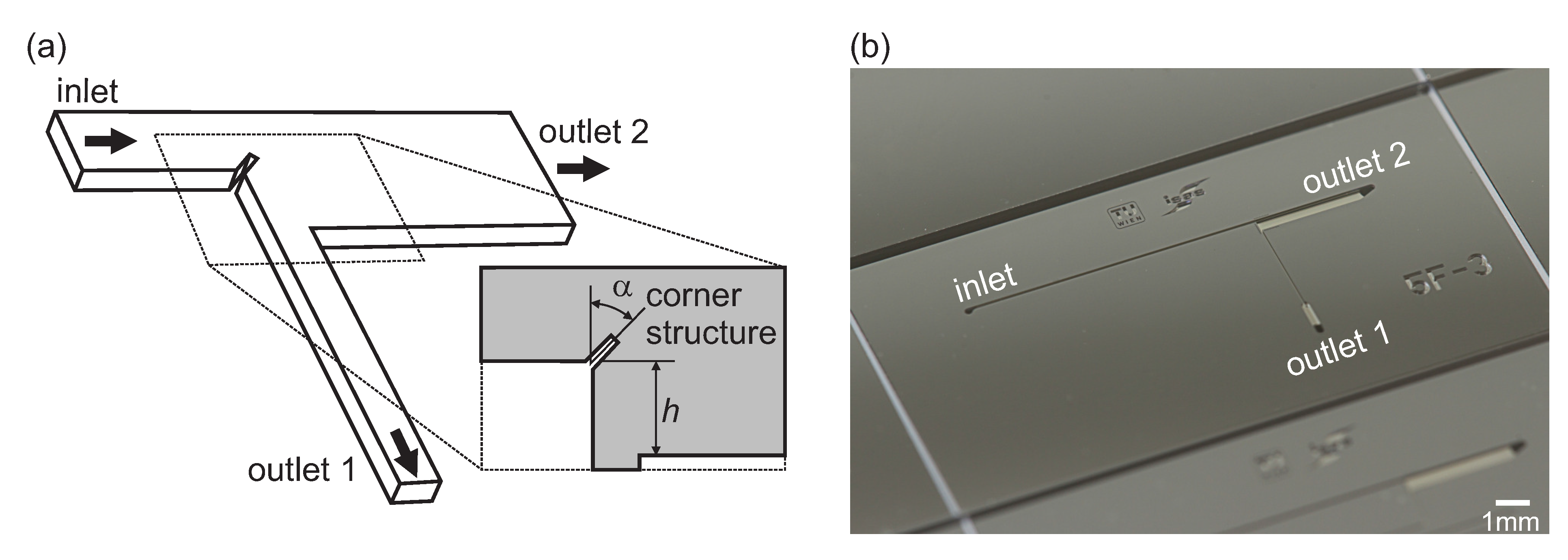
2.2. Device Fabrication

The microfluidic chip was fabricated applying standard micromachining techniques with a silicon (Si) wafer (350 µm thick, <100> orientation, ø = 100 mm, double side polished) as substrate and a borosilicate glass wafer (500 µm thick, ø = 100 mm, double side polished) as cover. Initially, inlet and outlets for the fluid connections were patterned on the bottom side of the Si wafer by lithographic steps. The microfluidic channel was fabricated into the top side of the Si wafer. On both sides Si was structured using deep reactive ion etching (DRIE). Finally, the glass wafer was anodically bonded onto the top side of the silicon wafer, sealing the microfluidic channel structure. A detailed description of the fabrication of microfluidic devices using glass and silicon has been published recently [40]. On a 100 mm wafer 20 devices are fabricated. Figure 1b shows a photograph of a diced microfluidic chip.

2.3. Particle Suspension and Blood Preparation

For the streamline visualization measurement in Section 3.2 a sample with 0.1% v/v fluorescent green 3 µm sized polystyrene particles (G0300, Distrilab B.V., Leusden, The Netherlands) was prepared by diluting the suspension with a density-matched solution of 14% w/w sucrose in deionized (DI) water. To avoid sticking of the fluorescent particles to the channel walls, the chip was preflushed with a sterile-filtered solution of 2 g/L alginic acid sodium salt (Sigma-Aldrich, St. Louis, MO, USA) in DI water. After a settling time of 2 min the visualization of the streamlines was started.
For the plasma separation experiments blood was collected by venipuncture from healthy donors taking part in a clinical study, approved by the local institutional ethics board. The blood sample was diluted with a phosphate buffered saline (PBS) solution by a factor of 20 which led to the best performance for the current design. Similar dilution rates are reported by other groups using cell deviation mechanisms [41]. Generally, there is a trade-off between dilution rate and separation efficiency. To prevent sedimentation of blood cells the sample was continuously agitated with a magnetic syringe stirrer (neMIX, Cetoni, Korbussen, Germany) before entering the chip.

2.4. Experimental Setup

Fluorescence images were captured with a Nikon AZ 100 upright microscope (Nikon, Tokyo, Japan), equipped with an AZ Plan Fluor 5x objective and a digital camera (D5100, Nikon). The exposure time was varied from 1/200 s to 3 s according to the light intensity and the applied flow rate. The fluorescent particles were stimulated with a mercury arc lamp (Intensilight C-HGFI, Nikon) and an optical single-band filter set (GFP-3035D-NTE, Semrock, Rochester, NY, USA).
The microfluidic device was connected with standard PEEK (polyether ether ketone) tubings (outer diameter ø = 794 µm, inner diameter ø = 250 µm) via thermoplastic bonded-port connectors (Labsmith CapTite, Mengel Engineering, Virum, Denmark), which are glued onto the backside of the silicon device, in combination with a screwed-in fitting (Labsmith CapTite). This world-to-chip interface is illustrated in the electronic supplementary information, Figure S1. To provide stable flow rates a syringe pump (neMESYS, Cetoni, Korbussen, Germany) was used in all experiments. For the blood plasma separation experiments another syringe pump (Cetoni neMESYS) was used to set the plasma outflow rate.

2.5. Procedures for Image Analysis

To acquire the size of the vortex area, all images were analyzed with Photoshop CS5 (Adobe Systems Incorporated, San Jose, CA, USA). In the simulated streamline plots the perimeter of the outmost circulating streamline was traced. The area of the recirculation was measured using the histogram tool.
Micrographs of the fluorescent particle traces were initially posterized. This simplifies the differentiation between circulating and passing-by streamlines. Subsequent steps are equal to the postprocessing of the simulation results.

3. Measurements and Results

An optimization of the corner structured channel design was performed utilizing numerical models in Section 3.1. To determine the microvortex enhancement and compare the simulations with the measurements, a streamline visualization using fluorescent particles was conducted in Section 3.2. A potential application of sudden expansion channels for on-chip sample preparation is the separation of human blood plasma. Inducing microvortices in expansion channels increases the plasma extraction yield [24]. In Section 3.3 the effect of enhancing the vortex area by the corner structured chip is investigated in respect to separation efficiency.

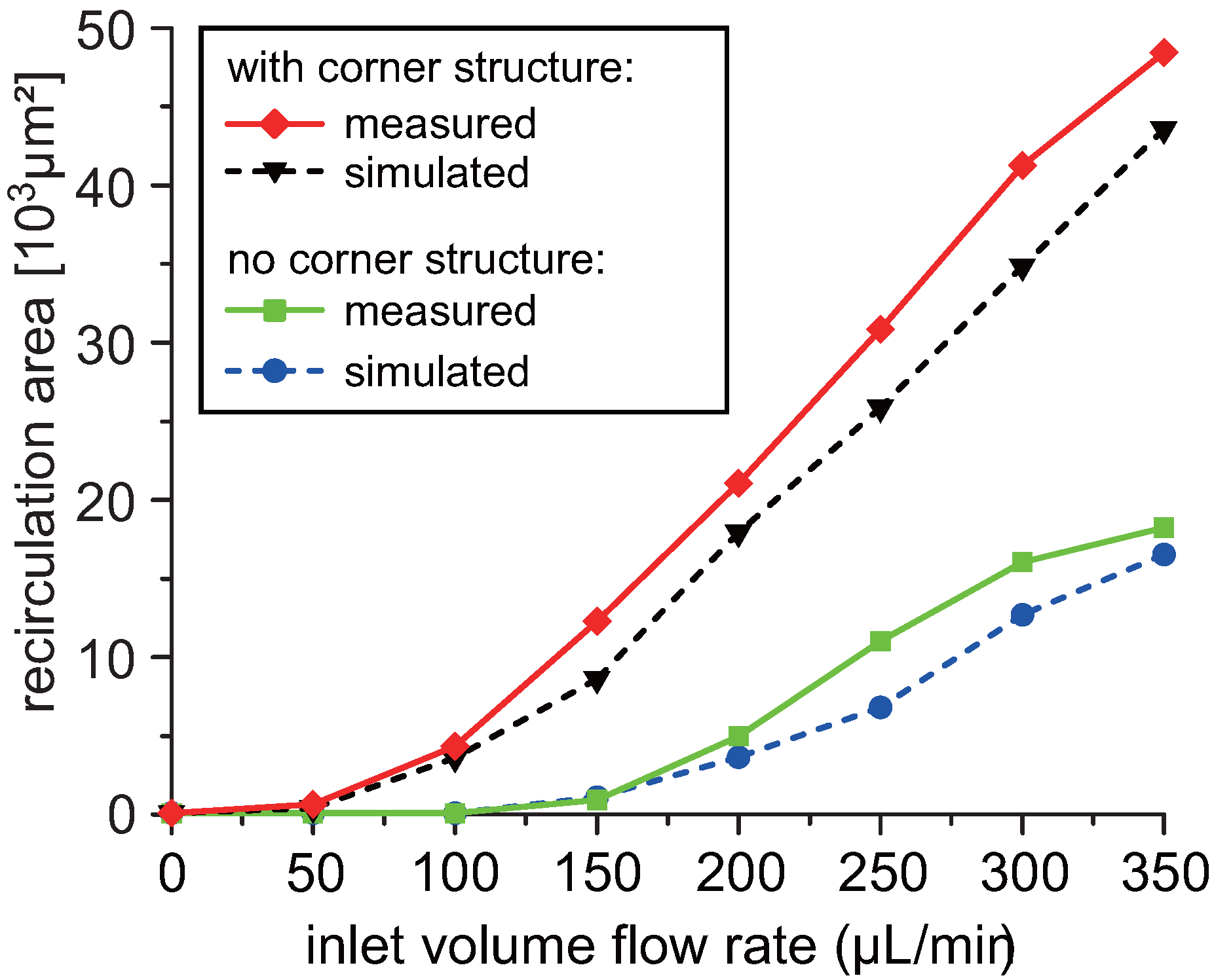
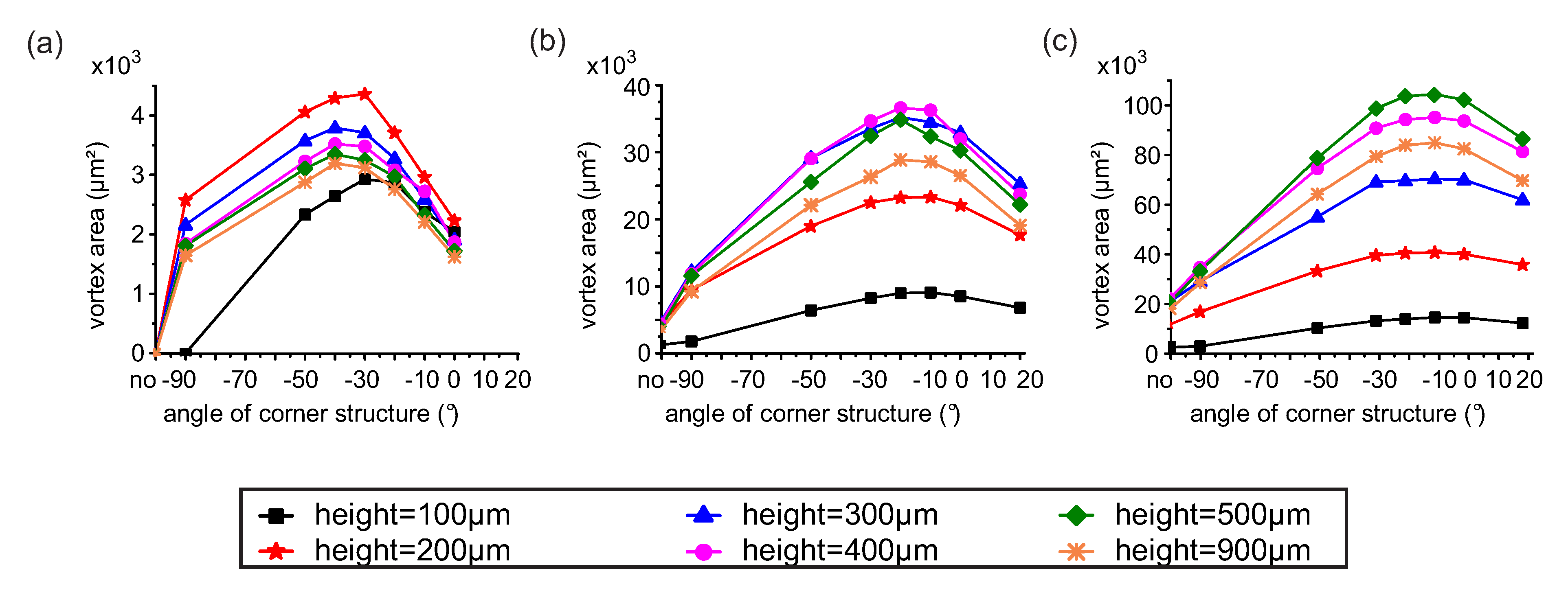
3.1. Design Optimization

In order to optimize the channel geometry and the corner structure for a maximum vortex area, a computational analysis was performed according to Section 2.1. The computational data in Figure 2 shows a representative velocity and streamline profile of a backward-facing step in the channel with (a) and without (b) corner structure at a volume flow rate of 150 µL/min. This comparison illustrates the formation of microvortices by the corner structure whereby no recirculation can be observed in designs with a plain backward-facing step.
Figure 2. Velocity streamlines in a sudden expansion channel (h = 400 µm) with (a) and without (b) the corner structure (width × length: 10 µm × 40 µm, α = –30°) at Re = 25. Re was calculated at the inlet channel (width × depth: 100 µm × 100 µm) with inlet flow rate 150 µL/min. The color of streamlines indicates the velocity magnitude (m/s).
Micromachines 06 00239 g002
The Reynolds number Re is the ratio of inertial to viscous forces in flow (Re = ρuDh, with ρ, u, Dh and µ being the density, mean downstream velocity, hydraulic diameter and dynamic viscosity, respectively). The hydraulic diameter Dh can be defined as Dh = 4 · A/P, with A being the cross sectional area and P the wetted perimeter of the microfluidic channel prior to the expansion. For the proposed chip design and flow rates, Re is in the range of 5 to 60 in the inlet channel, stating the laminar flow regime.
In the CFD analysis, three parameters were varied to maximize the vortex area: step height h, angle of the corner structure α and volume flow rate. To visualize the microvortices in the microfluidic channel, velocity streamlines were plotted. Next, the microvortex area was calculated using image processing tools as described in Section 2.5. Figure 3 summarizes the results of the simulation study. The three multiple line graphs (a), (b) and (c) represent the volume flow rates 100 µL/min, 200 µL/min and 300 µL/min, respectively. The microvortex area is plotted against the angle of the corner structure α, including the case of no corner structure, i.e., a channel with a plain backward-facing step design (values at the ordinate). An angle of 0° corresponds to a vertical corner structure protruding into the channel, i.e., perpendicular to the flow direction. Each line in the plot corresponds to an individual channel step height h.
Figure 3. Microvortex area as a function of the angle of the corner structure calculated in the simulation study for different step heights and inlet volume flow rates of 100 µL/min (a) 200 µL/min (b) and 300 µL/min (c).
Micromachines 06 00239 g003
Independently of the angle α and the step height h, the corner structure generally increases the microvortex area.
To identify the design which is best applicable for the wide flow rate range, the vortex area was normalized. Normalization enables a comparison of microvortex areas at different flow velocities with each other. Hence, three values, corresponding to 100 µL/min, 200 µL/min and 300 µL/min, represent the performance of a channel design. Subsequently, the mean value x and the standard deviation sx for each of the different channel geometries were calculated. Based on this data, the geometric dimension was chosen with respect to the highest mean value while having a low standard deviation (sx < 10%). This optimization scheme led to the optimum design featuring a step height h of 400 µm and an angle α of −30° (x = 87%, sx = 6%).
In summary, by applying the optimized corner structure to a sudden expansion channel (inlet channel width 100 µm, step height 400 µm, flow rate 200 µL/min) the microvortex area is increased by more than a factor of 4. This optimized design creates a channel constriction just before the expansion, resulting in a minimum channel width of about 65 µm. A plain backward-facing step design with an equivalent narrowed inlet channel width of 65 µm causes a smaller vortex. The improvement in microvortex area of the corner structured compared to a uniform narrowed channel for a volume flow rate of 200 µL/min amounts to approximately 40%.

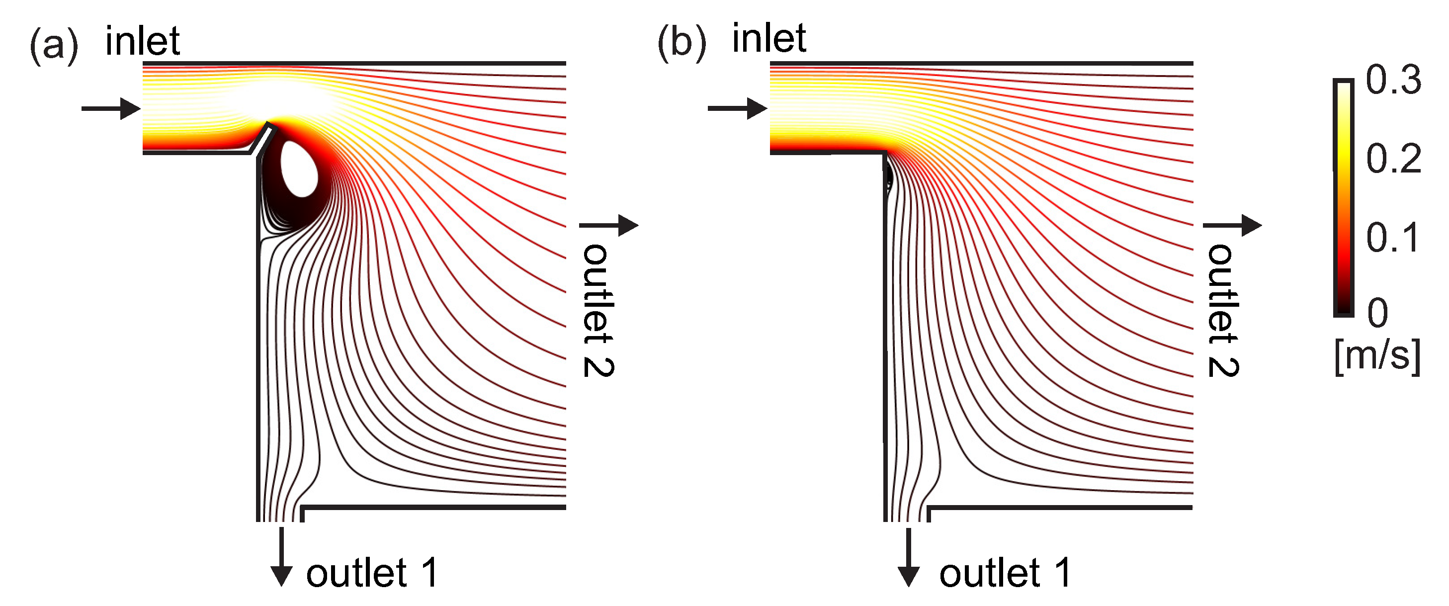
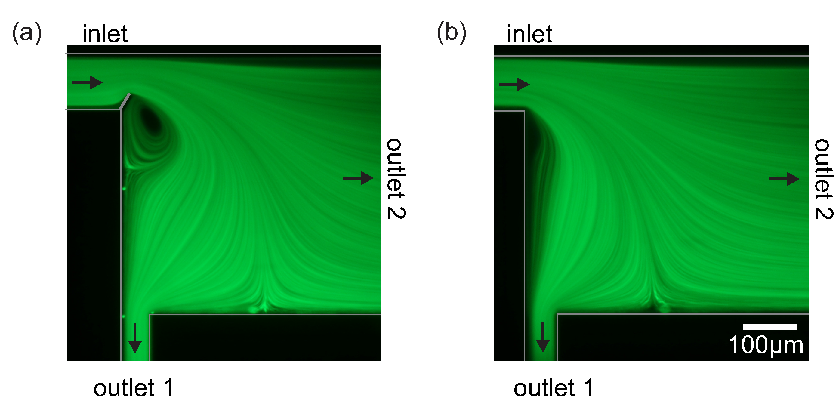
3.2. Streamline Visualization

To visualize and characterize the enlargement of the microvortex area by the corner structure a constant flow of a suspension with fluorescent particles was injected to trace the streamlines. Figure 4 compares the fluorescent particle trajectories of chips with (a) and without (b) corner structure at a constant flow rate of 150 µL/min. These measurements verify the previous simulation study, depicted in Figure 2. Introducing the corner structure lowers the volume flow rate necessary for vortex formation onset. Additional micrographs of fluorescent particle streamline measurements, comparing the plain backward-facing step channel versus the optimized corner structured chip, are available as electronic supplementary material in Figure S2.
Figure 4. Micrographs of fluorescent particle streamlines in the optimized sudden expansion channel with (a) and without (b) corner structure at Re = 25.
Micromachines 06 00239 g004
To characterize the formation and the enhancement of the microvortices the solution with the fluorescent particles was pumped through the microfluidic device at volume flow rates, ranging from 50 to 350 µL/min. Figure 5 compares the vortex areas of the simulation study (blue circles, black triangles) with the measured values (green rectangles, red diamonds). These results validate the simulation, which was performed according to Section 2.1. The difference between simulated and measured data arises from the fact that simulated streamlines are compared with measured particle trajectories and the neglection of particle-particle interactions.
The greatest influence on vortex formation and enhancement by the corner structure is observed at low flow rates. At a volume flow rate of 200 µL/min the vortex area is enhanced by a factor of 4.4, whereas at higher flow rates (up to 350 µL/min) the factor is still greater than 2.5. At flow rates below 150 µL/min the formation of a microvortex is only provided by the channel with the corner structure.
Furthermore, this figure reveals that, by applying the corner structure, the flow rate can be reduced without a decrease in vortex size.
Figure 5. Comparison of the simulated (dashed lines) and measured (solid lines) vortex area in the sudden expansion channel with and without corner structure as a function of the inlet volume flow rate.
Micromachines 06 00239 g005

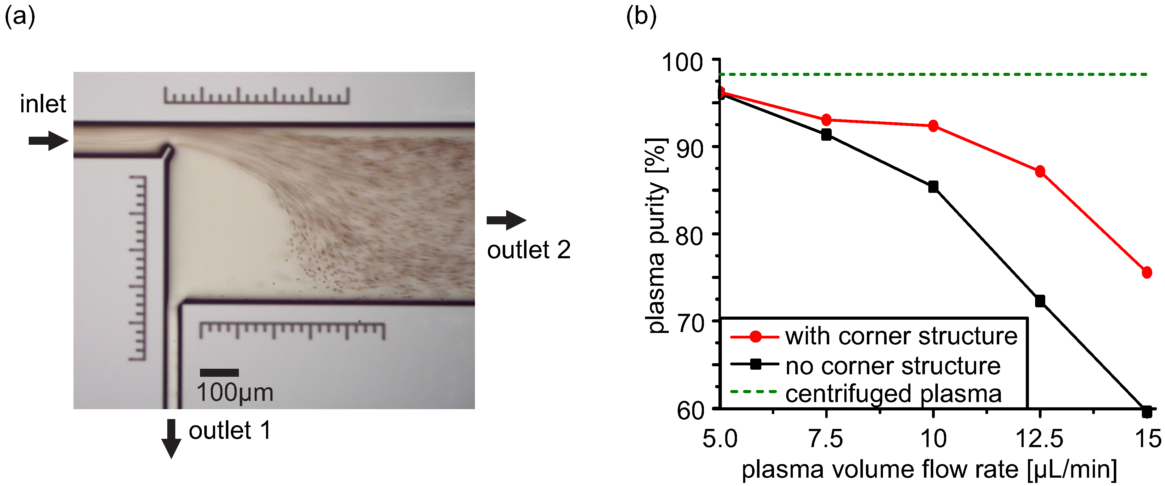
3.3. Human Blood Plasma Separation

As an example of integrated sample preparation, the corner structured chip was tested for the ability to separate plasma from anticoagulated human blood. Figure 6a depicts a micrograph of the separation using a sudden expansion channel with corner structure at a flow rate of 200 µL/min. During the measurements no hemolysis has been observed. As the red blood cells (RBCs), which constitute about 95% of all blood cells, are denser than the liquid phase, they do not enter the vortex. Hence, a larger vortex means a larger cell-free area. In addition, the corner structure as well as the sudden expansion geometrically enhances the cell-free layer, which forms due to hydrodynamic lift of deformable cells in shear flow. This phenomenon has been systematically investigated by Faivre et al. [42]. Thus, RBCs are concentrated at outlet 2, whereas plasma is extracted at outlet 1.
Figure 6. (a) Bright-field image of human blood plasma separation experiment at a flow rate of 200 µL/min. The concentrated blood stream exits at outlet 2. (b) Purity of plasma generated by the microfluidic chip with and without corner structure in comparison to centrifuged plasma.
Micromachines 06 00239 g006
A flow cytometer (Gallios, Beckman Coulter Inc., Miami, FL, USA) is used to determine the purity (the percentage of removed cells) and the quality of the generated plasma. The purity p is defined as p = 1 − cp/cf, where cp is the number of cells in the plasma fraction and cf is the number of cells in the feed (inlet) fraction.
Figure 6b compares the purity of conventional, i.e., generated with a bench-top centrifuge, plasma (dotted green) with plasma extracted from the microfluidic chip with (red circles) and without (black rectangles) corner structure. The inlet volume flow rate was kept constant at 200 µL/min, the plasma extraction rate was varied between 5 µL/min and 15 µL/min, corresponding to a yield (the percentage of plasma over the total volume) up to 7.5%.
At low plasma flow rates the designs with and without corner structure perform equally, attaining a plasma purity of over 95%. The purity of centrifuged plasma was about 98% due to the presence of microparticles < 3 µm. In the conducted flow cytometer measurement this is the maximum purity reached with standard benchtop centrifuges. By applying the corner structure at elevated plasma flow rates, a higher purity is reached compared to designs with a plain backward-facing step. At a flow rate of 12.5 µL/min the particle count in the plasma sample is reduced by more than 50% compared to the design without corner structure. This corresponds to an increased purity of 87%. As seen, especially at higher flow rates the corner structure increases plasma purity, reducing the trade-off between throughput and quality.
This proof-of-concept confirms that the corner structure increases the separation efficiency by enhancing the vortex area. Microscale blood fractionation is a research area of great interest. A variety of microfluidic devices with the aim of integrating blood plasma extraction have been investigated and reviewed [41,43,44], thereby harnessing the advantages of miniaturized systems. Although, in comparison the yield of the presented system is lower, there are several possibilities to improve the performance, e.g., with a symmetric geometry [45], parallelization [46] or installing units in series [23,47].

4. Conclusions

This work reports on a microfluidic chip which utilizes a novel corner structure in a sudden expansion channel to generate and enhance microvortices under laminar flow conditions. By optimizing the geometric properties, the vortex area is increased by more than a factor of 4 compared to plain backward-facing steps at 200 µL/min, which was proven by fluorescent streamline visualization. In addition to the enlarged microvortex area, the new design exhibits a lower minimal volume flow rate that triggers microvortex formation.
Consequently, the proposed channel design can be used to improve separation of cells and particles in suspension, hereby meeting typical challenges of on-chip sample preparation. The extraction of human blood plasma is presented as an application of the proposed chip design. An enhanced purity of more than 90% is reached with a cell count reduction by a factor of 2 compared to channels without corner structure.
Channel protrusions, such as the presented corner structure, represent a simple method to improve the performance of microvortex-based microfluidics.

Supplementary Materials

Supplementary materials can be accessed at: https://www.mdpi.com/2072-666X/6/2/239/s1.

Acknowledgments

For the sensor fabrication and technical support we thank Edda Svasek and Peter Svasek (MEMS Technology Lab of the Institute of Sensor and Actuator Systems and Center for Micro- and Nanostructures, Vienna University of Technology). We gratefully acknowledge the support of the Austrian Research Promotion Agency, grant No. 829651.

Author Contributions

Anna Haller conceived the idea for the project, designed and performed the experiments, analyzed the data and wrote the paper. Andreas Spittler designed and performed the flow cytometer experiments and analyzed the data. Lukas Brandhoff performed experiments and revised the manuscript. Helene Zirath performed experiments and revised the manuscript. Dietmar Puchberger-Enengl contributed reagents and materials and revised the manuscript. Franz Keplinger revised the manuscript and provided senior expertise. Michael J. Vellekoop conceived the idea for the project, revised the manuscript and provided senior expertise.

Conflicts of Interest

The authors declare no conflict of interest.

References

  1. Mach, A.J.; Adeyiga, O.B.; di Carlo, D. Microfluidic sample preparation for diagnostic cytopathology. Lab Chip 2013, 13, 1011–1026. [Google Scholar] [CrossRef] [PubMed]
  2. Culbertson, C.T.; Mickleburgh, T.G.; Stewart-James, S.A.; Sellens, K.A.; Pressnall, M. Micro total analysis systems: Fundamental advances and biological applications. Anal. Chem. 2014, 86, 95–118. [Google Scholar] [CrossRef] [PubMed]
  3. Verpoorte, E. Microfluidic chips for clinical and forensic analysis. Electrophoresis 2002, 23, 677–712. [Google Scholar] [CrossRef] [PubMed]
  4. Amini, H.; Lee, W.; di Carlo, D. Inertial microfluidic physics. Lab Chip 2014, 14, 2739–2761. [Google Scholar] [CrossRef] [PubMed]
  5. Shelby, J.P.; Lim, D.S.W.; Kuo, J.S.; Chiu, D.T. Microfluidic systems: High radial acceleration in microvortices. Nature 2003, 425, 38. [Google Scholar] [CrossRef] [PubMed]
  6. Shelby, J.P.; Chiu, D.T. Controlled rotation of biological micro- and nano-particles in microvortices. Lab Chip 2004, 4, 168–170. [Google Scholar] [CrossRef] [PubMed]
  7. Chiu, D.T. Cellular manipulations in microvortices. Anal. Bioanal. Chem. 2007, 387, 17–20. [Google Scholar] [CrossRef] [PubMed]
  8. Mach, A.J.; Kim, J.H.; Arshi, A.; Hur, S.C.; di Carlo, D. Automated cellular sample preparation using a Centrifuge-on-a-Chip. Lab Chip 2011, 11, 2827–2834. [Google Scholar] [CrossRef] [PubMed]
  9. Pertaya-Braun, N.; Baier, T.; Hardt, S. Microfluidic centrifuge based on a counterflow configuration. Microfluid. Nanofluid. 2011, 12, 317–324. [Google Scholar] [CrossRef]
  10. Lee, J.; Ha, J.; Bahk, Y.; Yoon, S.; Arakawa, T.; Ko, J.; Shin, B.; Shoji, S.; Go, J. Microfluidic centrifuge of nano-particles using rotating flow in a microchamber. Sens. Actuators B Chem. 2008, 132, 525–530. [Google Scholar] [CrossRef]
  11. Park, J.S.; Song, S.H.; Jung, H.I. Continuous focusing of microparticles using inertial lift force and vorticity via multi-orifice microfluidic channels. Lab Chip 2009, 9, 939–948. [Google Scholar] [CrossRef] [PubMed]
  12. Wang, X.; Zhou, J.; Papautsky, I. Vortex-aided inertial microfluidic device for continuous particle separation with high size-selectivity, efficiency, and purity. Biomicrofluidics 2013, 7, 044119. [Google Scholar] [CrossRef]
  13. Hsu, C.H.; Di Carlo, D.; Chen, C.; Irimia, D.; Toner, M. Microvortex for focusing, guiding and sorting of particles. Lab Chip 2008, 8, 2128–2134. [Google Scholar] [CrossRef] [PubMed]
  14. Zhang, W.; Frakes, D.H.; Babiker, H.; Chao, S.H.; Youngbull, C.; Johnson, R.H.; Meldrum, D.R. Simulation and experimental characterization of microscopically accessible hydrodynamic microvortices. Micromachines 2012, 3, 529–541. [Google Scholar] [CrossRef]
  15. Zhou, J.; Kasper, S.; Papautsky, I. Enhanced size-dependent trapping of particles using microvortices. Microfluid. Nanofluid. 2013, 15, 611–623. [Google Scholar] [CrossRef]
  16. Petit, T.; Zhang, L.; Peyer, K.E.; Kratochvil, B.E.; Nelson, B.J. Selective trapping and manipulation of microscale objects using mobile microvortices. Nano Lett. 2012, 12, 156–160. [Google Scholar] [CrossRef] [PubMed]
  17. Hur, S.C.; Mach, A.J.; di Carlo, D. High-throughput size-based rare cell enrichment using microscale vortices. Biomicrofluidics 2011, 5, 022206. [Google Scholar] [CrossRef]
  18. Sollier, E.; Go, D.E.; Che, J.; Gossett, D.R.; O’Byrne, S.; Weaver, W.M.; Kummer, N.; Rettig, M.; Goldman, J.; Nickols, N.; et al. Size-selective collection of circulating tumor cells using Vortex technology. Lab Chip 2014, 14, 63–77. [Google Scholar] [CrossRef] [PubMed]
  19. Lee, M.G.; Choi, S.; Park, J.K. Rapid multivortex mixing in an alternately formed contraction-expansion array microchannel. Biomed. Microdevices 2010, 12, 1019–1026. [Google Scholar] [CrossRef] [PubMed]
  20. Lee, J.; Kwon, S. Mixing efficiency of a multilamination micromixer with consecutive recirculation zones. Chem. Eng. Sci. 2009, 64, 1223–1231. [Google Scholar] [CrossRef]
  21. Shih, T.R.; Chung, C.K. A high-efficiency planar micromixer with convection and diffusion mixing over a wide Reynolds number range. Microfluid. Nanofluid. 2007, 5, 175–183. [Google Scholar] [CrossRef]
  22. Kim, Y.; Lee Chung, B.; Ma, M.; Mulder, W.J.M.; Fayad, Z.A.; Farokhzad, O.C.; Langer, R. Mass production and size control of lipid-polymer hybrid nanoparticles through controlled microvortices. Nano Lett. 2012, 12, 3587–3591. [Google Scholar] [CrossRef] [PubMed]
  23. Marchalot, J.; Fouillet, Y.; Achard, J.L. Multi-step microfluidic system for blood plasma separation: Architecture and separation efficiency. Microfluid. Nanofluid. 2014, 17, 167–180. [Google Scholar] [CrossRef]
  24. Sollier, E.; Cubizolles, M.; Fouillet, Y.; Achard, J.L. Fast and continuous plasma extraction from whole human blood based on expanding cell-free layer devices. Biomed. Microdevices 2010, 12, 485–497. [Google Scholar] [CrossRef] [PubMed]
  25. Sajeesh, P.; Sen, A.K. Particle separation and sorting in microfluidic devices: A review. Microfluid. Nanofluid. 2014, 17, 1–52. [Google Scholar] [CrossRef]
  26. Liou, T.M.; Lin, C.T. Study on microchannel flows with a sudden contraction-expansion at a wide range of Knudsen number using lattice Boltzmann method. Microfluid. Nanofluid. 2013, 16, 315–327. [Google Scholar] [CrossRef]
  27. Nejat, A.; Kowsary, F.; Hasanzadeh-Barforoushi, A.; Ebrahimi, S. Unsteady pulsating characteristics of the fluid flow through a sudden expansion microvalve. Microfluid. Nanofluid. 2014, 17, 623–637. [Google Scholar] [CrossRef]
  28. Balan, C.M.; Broboana, D.; Balan, C. Investigations of vortex formation in microbifurcations. Microfluid. Nanofluid. 2012, 13, 819–833. [Google Scholar] [CrossRef]
  29. Liu, S.J.; Wei, H.H.; Hwang, S.H.; Chang, H.C. Dynamic particle trapping, release, and sorting by microvortices on a substrate. Phys. Rev. E 2010, 82, 026308. [Google Scholar] [CrossRef]
  30. Yazdi, S.; Ardekani, A.M. Bacterial aggregation and biofilm formation in a vortical flow. Biomicrofluidics 2012, 6, 044114. [Google Scholar] [CrossRef]
  31. Shang, X.P.; Cui, X.G.; Huang, X.Y.; Yang, C. Vortex generation in a microfluidic chamber with actuations. Exp. Fluids 2014, 55, 1758. [Google Scholar] [CrossRef]
  32. Qin, L.; Vermesh, O.; Shi, Q.; Heath, J.R. Self-powered microfluidic chips for multiplexed protein assays from whole blood. Lab Chip 2009, 9, 2016–2020. [Google Scholar] [CrossRef] [PubMed]
  33. Arifin, D.R.; Yeo, L.Y.; Friend, J.R. Microfluidic blood plasma separation via bulk electrohydrodynamic flows. Biomicrofluidics 2007, 1, 14103. [Google Scholar] [CrossRef] [PubMed]
  34. Yeo, L.Y.; Hou, D.; Maheshswari, S.; Chang, H.C. Electrohydrodynamic surface microvortices for mixing and particle trapping. Appl. Phys. Lett. 2006, 88, 233512. [Google Scholar] [CrossRef]
  35. Fishler, R.; Mulligan, M.K.; Sznitman, J. Mapping low-Reynolds-number microcavity flows using microfluidic screening devices. Microfluid. Nanofluid. 2013, 15, 491–500. [Google Scholar] [CrossRef]
  36. Tsai, C.H.; Yeh, C.P.; Lin, C.H.; Yang, R.J.; Fu, L.M. Formation of recirculation zones in a sudden expansion microchannel with a rectangular block structure over a wide Reynolds number range. Microfluid. Nanofluid. 2011, 12, 213–220. [Google Scholar] [CrossRef]
  37. Tsai, C.H.; Lin, C.H.; Fu, L.M.; Chen, H.C. High-performance microfluidic rectifier based on sudden expansion channel with embedded block structure. Biomicrofluidics 2012, 6, 24108–241089. [Google Scholar] [CrossRef] [PubMed]
  38. Biswas, G.; Breuer, M.; Durst, F. Backward-facing step flows for various expansion ratios at low and moderate Reynolds numbers. J. Fluids Eng. 2004, 126, 362. [Google Scholar] [CrossRef]
  39. Haller, A.; Buchegger, W.; Vellekoop, M. Towards an optimized blood plasma separation chip: Finite element analysis of a novel corner structure in a backward-facing step. Procedia Eng. 2011, 25, 439–442. [Google Scholar] [CrossRef]
  40. Iliescu, C.; Taylor, H.; Avram, M.; Miao, J.; Franssila, S. A practical guide for the fabrication of microfluidic devices using glass and silicon. Biomicrofluidics 2012, 6, 16505–1650516. [Google Scholar] [CrossRef] [PubMed]
  41. Yu, Z.T.F.; Aw Yong, K.M.; Fu, J. Microfluidic blood cell sorting: Now and beyond. Small 2014, 10, 1687–703. [Google Scholar] [CrossRef] [PubMed]
  42. Faivre, M.; Abkarian, M.; Bickraj, K.; Stone, H.A. Geometrical focusing of cells in a microfluidic device: An approach to separate blood plasma. Biorheology 2006, 43, 147–159. [Google Scholar] [PubMed]
  43. Hou, H.W.; Bhagat, A.A.S.; Lee, W.C.; Huang, S.; Han, J.; Lim, C.T. Microfluidic devices for blood fractionation. Micromachines 2011, 2, 319–343. [Google Scholar] [CrossRef]
  44. Kersaudy-Kerhoas, M.; Sollier, E. Micro-scale blood plasma separation: From acoustophoresis to egg-beaters. Lab Chip 2013, 13, 3323–3346. [Google Scholar] [CrossRef] [PubMed]
  45. Sollier, E.; Rostaing, H.; Pouteau, P.; Fouillet, Y.; Achard, J.L. Passive microfluidic devices for plasma extraction from whole human blood. Sensors Actuators B Chem. 2009, 141, 617–624. [Google Scholar] [CrossRef]
  46. Mach, A.J.; di Carlo, D. Continuous scalable blood filtration device using inertial microfluidics. Biotechnol. Bioeng. 2010, 107, 302–311. [Google Scholar] [CrossRef] [PubMed]
  47. Kersaudy-Kerhoas, M.; Kavanagh, D.M.; Dhariwal, R.S.; Campbell, C.J.; Desmulliez, M.P.Y. Validation of a blood plasma separation system by biomarker detection. Lab Chip 2010, 10, 1587–1595. [Google Scholar] [CrossRef] [PubMed]

