Article

Manufacturing and Characterization of a Thermoelectric Energy Harvester Using the CMOS-MEMS Technology

1
Department of Mechanical Engineering, National Chung Hsing University, Taichung 402, Taiwan
2
Department of Civil and Environmental Engineering, National University of Kaohsiung, Kaohsiung 811, Taiwan
*
Author to whom correspondence should be addressed.
Micromachines 2015, 6(10), 1560-1568; https://doi.org/10.3390/mi6101439
Submission received: 15 September 2015 / Revised: 9 October 2015 / Accepted: 12 October 2015 / Published: 16 October 2015
(This article belongs to the Special Issue CMOS-MEMS Sensors and Devices)

Abstract

:
The fabrication and characterization of a thermoelectric energy harvester using the complementary metal oxide semiconductor (CMOS)-microelectromechanical system (MEMS) technology were presented. The thermoelectric energy harvester is composed of eight circular energy harvesting cells, and each cell consists of 25 thermocouples in series. The thermocouples are made of p-type and n-type polysilicons. The output power of the energy harvester relies on the number of the thermocouples. In order to enhance the output power, the energy harvester increases the thermocouple number per area. The energy harvester requires a post-CMOS process to etch the sacrificial silicon dioxide layer and the silicon substrate to release the suspended structures of hot part. The experimental results show that the energy harvester has an output voltage per area of 0.178 mV·mm−2·K−1 and a power factor of 1.47 × 10⁻³ pW·mm−2·K−2.

1. Introduction

Thermoelectric energy harvesters can be applied in electronic devices and equipments as an auxiliary electrical power source [1,2,3,4], and they have a capability of converting waste heat into electrical power to achieve waste energy recycling. Several devices were miniaturized using MEMS technology [4,5,6,7,8]. Microdevices fabricated by this technology have the benefits of small volume, high performance and low cost [9,10,11,12]. Recently, many studies have employed MEMS technology to develop various energy harvesters. For instance, Su et al. [13] presented a micromachined thermoelectric energy harvester with 6 μm high polycrystalline silicon germanium thermocouples. The area of the harvester was 1 mm × 2.5 mm. The harvester had an output voltage of 1.49 V and an output power of 0.4 μW at the temperature difference of 3.5 K. Huesgen et al. [14] fabricated a micro thermoelectric generator using MEMS technology. To enhance the output power, the thermocouples of the generator were made of p-Bi0.5Sb1.5Te3 and n-Bi0.87Sb0.13, in which deposited by thin-film processes with high integration density on the wafer surface. The power factors of the generator were 8.14 × 10⁻³ μW·mm−2·K−2. Yu et al. [15] utilized the CMOS process to make thermoelectric energy generator with an efficient heat dissipation path. To reduce the internal thermal-contact resistance of the energy generator, the silicon substrate of the generator was etched into two comb-shaped blocks thermally isolated from each other, which formed the hot and cold sides. The thin-film-based thermal legs were located between the two blocks along the winding split line. The measured open-circuit voltage of the generator was 146 mV·K−1. Yuan et al. [16] employ MEMS technology to manufacture a planar micro thermoelectric generator. To obtain a better performance under a large variety of heat sources, the micro thermoelectric generator with a large thermal resistance was designed. The generator was built of two periodically etched silicon substrates that were respectively utilized as heat concentrator and heat evacuator. To prevent the direct heat loss from concentrator to evacuator, the substrates were etched as the thick air cavities. The maximum output power of the thermoelectric generator was 138 μW·cm−2 when the input power was 4 W·cm−2. Kouma et al. [17] fabricated a micro thermoelectric generator with high aspect ratio and high integration density thermocouples. To improve the thermoelectric property, the fabrication of the micro generator adopted thermoelectric nanopowders filled in a photosensitive glass mold using aerosol deposition, followed by hot isostatic pressing. The thermocouples had an aspect ratio of 3.5. The thermoelectric generator had an output voltage per area of 0.16 V·cm−2·K−1 and an output power factor of 9.3 μW·cm−2·K−2. Kao et al. [18] developed a thermoelectric energy harvester using the commercial CMOS process. The measurement results showed that the harvester had an output voltage per area of 0.093 mV mm−2·K−1 and a power factor of 6.4 × 10⁻⁷ μW·mm−2·K−2. In this work, we develop a thermoelectric energy harvester using the commercial CMOS process. The fabrication energy harvester in this work is easier than that of Su et al. [13], Huesgen et al. [14], Yuan et al. [16] and Kouma et al. [17]. The output power of the energy harvester in this work exceeds that of Kao et al. [18]
MEMS devices made by the commercial CMOS process are called CMOS-MEMS technology [19,20,21]. Many microsensors and microactuators have been manufactured using this technology [22,23]. In this work, we fabricate a thermoelectric energy harvester using the CMOS-MEMS technology. This technology usually requires a post-CMOS process to add functional films [24,25,26] and to release the suspended structures [27,28,29]. To obtain the suspended structures of hot part, the thermoelectric energy harvester needs a post-CMOS process to etch the sacrificial silicon dioxide layer and the silicon substrate. The structure of the thermoelectric energy harvester consists of eight circular energy harvesting cells, and each cell is constructed by 25 thermocouples in series. The output power of the thermoelectric energy harvester depends on the temperature difference between the hot and cold parts of the thermocouples. To increase the temperature difference of the thermocouples, the hot part of the thermocouples is designed as suspended structures to decrease heat-sinking.

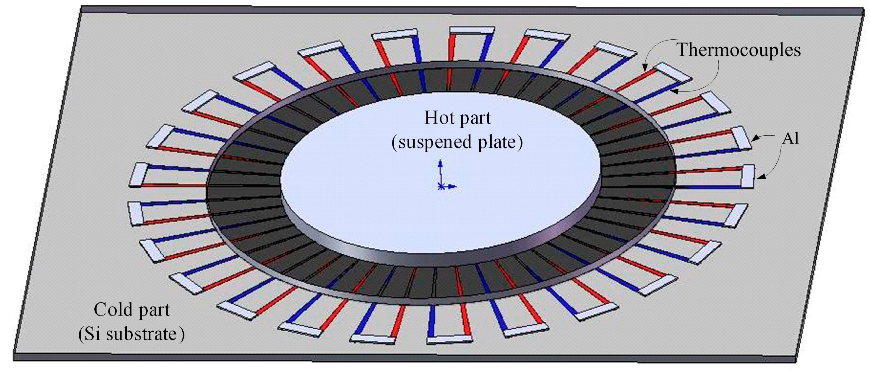
2. Structure of the Energy Harvester

The thermoelectric energy harvester is made up of eight energy harvesting cells in series. Figure 1 illustrates the schematic structure of an energy harvesting cell. The diameter of an energy harvesting cell is 360 μm. Each harvesting cell is composed of 25 thermocouples in series. Each thermocouple is constructed by p-type and n-type polysilicon strips. Dimensions of each polysilicon strip are 2 μm wide, 130 μm long and 0.2 μm thick. As shown in Figure 1, the energy harvesting cell consists of a hot part and a cold part. The hot part of the energy harvesting cell is the junctions of n-type and p-type polysilicon strips located on the suspended plate, and the cold part of the energy harvesting cell is the other junctions of n-type and p-type polysilicon strips anchored on the silicon substrate. The suspended plate of the hot part is sustained by the thermocouples. The p-type and n-type polysilicon strips in the hot part and cold part are connected with aluminum each other, as shown in Figure 1.
The output power of the thermoelectric energy harvester is proportional to the temperature difference between the hot and cold parts. In addition, the hot part of the harvester is suspended to decrease heat sink. The cold part of the harvester covers with a silicon dioxide layer of 6 μm to insulate the conduction of heat source. The finite element method software, CoventorWare, was employed to simulate the temperature distribution of the thermoelectric energy harvester. The model of the energy harvester is established in accordance with Figure 1, followed by meshing the model using the triangular element. The materials of the energy harvester contain polysilicon, silicon dioxide, aluminum, and silicon substrate. The thermal conductivities of the materials [30] are polysilicon, 31 W/m·K; aluminum, 237 W/m·K; silicon dioxide, 1.25 W/m·K; silicon substrate, 149 W/m·K. The ambient temperature of 293 K and thermal flux of 20 pW/μm2 are set. Figure 2 reveals the simulation of temperature distribution for the thermoelectric energy harvester. The results showed that the temperature difference between the hot and cold parts of the thermocouples was 15 K.
Figure 1. Structure of an energy harvesting cell.
Micromachines 06 01439 g001
Figure 2. Simulated temperature distribution for the thermoelectric energy harvester.
Micromachines 06 01439 g002
The output voltage of the thermoelectric energy harvester is given by [31]:
V out = n ( α p α n ) Δ T
where n represents the number of thermocouples in series; αp is the Seebeck coefficient of p-type polysilicon; αn is the Seebeck coefficient of n-type polysilicon; ΔT is the temperature difference of the hot and cold parts in the thermoelectric energy harvester and Vout is the output voltage of the thermoelectric energy harvester. According to Equation (1), we know that the output voltage of the energy harvester is proportional to the number of thermocouples and the temperature difference of the hot and cold parts, ΔT. The output voltage relies on the Seebeck coefficients of p-type polysilicon, αp, and n-type polysilicon, αn.
In this design, each harvesting cell has 25 thermocouples, so the number of thermocouples in the thermoelectric energy harvester is 200. The difference of Seebeck coefficient of αp − αn measured by a polysilicon thermocouple test-key is 0.0014 mV/K. The values n = 200 and αp − αn = 0.0014 mV/K are substituted into Equation (1), and then the relation between the output voltage and temperature difference for the energy harvester can be yielded. Figure 3 depicts the simulated output voltage of the thermoelectric energy harvester. The simulate results reveal that the thermoelectric energy harvester has an output voltage of about 2.8 mV at the temperature difference of 10 K and an output voltage of about 4.2 mV at the temperature difference of 15.
Figure 3. Simulated output voltage and power of the thermoelectric energy harvester.
Micromachines 06 01439 g003
When connecting an external resistor, the output power of the energy harvester can be used. If the internal resistance of the energy harvester equals to the external resistance, the maximum output power of the energy harvester can be expressed as [32]:
P out = V out 2 4 R
where Vout represents the output voltage of the energy harvester, R is the resistance of the energy harvester and Pout is the output power of the energy harvester. In this design, the resistance of the energy harvester is 8 kΩ. The values n = 200, αp − αn = 0.0014 mV/K, R = 8 kΩ and the output voltage in Figure 1 are substituted into Equation (2), the maximum output power of the thermoelectric energy harvester can be obtained. Figure 3 presents the simulated maximum output power of the thermoelectric energy harvester. The simulated results show that the thermoelectric energy harvester has an output power of 0.245 pW at the temperature difference of 10 K and an output power of 0.55 pW at the temperature difference of 15 K.

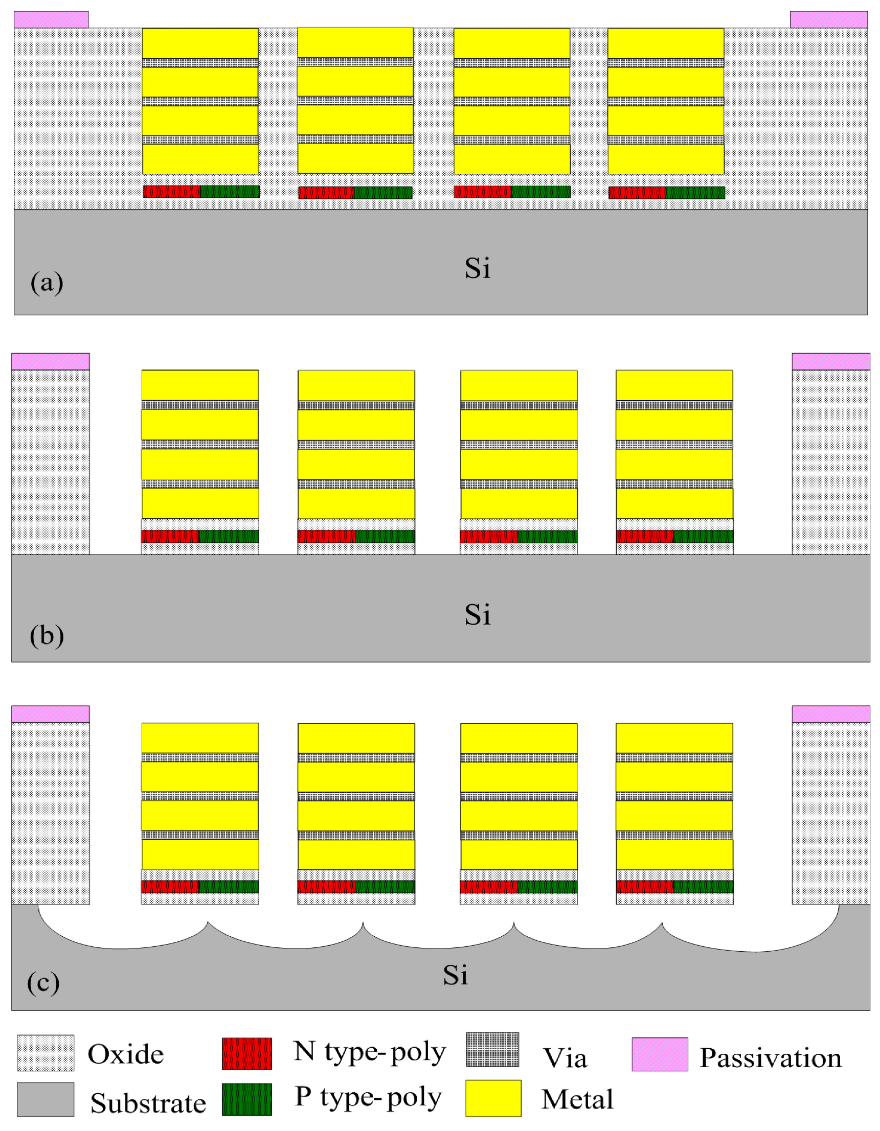
3. Fabrication of the Energy Harvester

The thermoelectric energy harvester was manufactured utilizing the commercial 0.18 μm CMOS process of Taiwan Semiconductor Manufacturing Company (TSMC). Figure 4 illustrates the fabrication flow of the thermoelectric energy harvester. The cross-sectional view of the thermoelectric energy harvester after completion of the CMOS process is shown in Figure 4a.
To obtain the suspended structures of the hot part, the thermoelectric energy harvester needed a post-process to remove the sacrificial materials of silicon dioxide and silicon substrate [33,34,35] Figure 4b displays the etching of the silicon dioxide layer. The sacrificial silicon dioxide layer was etched using CHF3/O2 reactive ion etching (RIE) to expose the silicon substrate. Then, the silicon substrate was etched using XeF2 RIE to release the suspended structure of hot part in the energy harvester. The removing of the silicon substrate is shown in Figure 4c. The p-type and n-type polysilicons in the thermocouples were connected with the aluminum layer. The profile of the thermoelectric energy harvester was measured using a scanning electron microscope (SEM) [36]. Figure 5 shows a SEM image of the thermoelectric energy harvester after the post-process. As shown in Figure 5, the thermoelectric energy harvester contains eight energy harvesting cells. Figure 6 depicts an SEM image of an energy harvesting cell. As shown in Figure 6, the energy harvesting cell consists of 25 thermocouples, and the suspended circular plat locates at the center position.
Figure 4. Fabrication flow of the thermoelectric energy harvester. (a) after the complementary metal oxide semiconductor (CMOS) process; (b) etching the silicon dioxide layer; (c) etching the silicon substrate.
Micromachines 06 01439 g004
Figure 5. SEM image of the thermoelectric energy harvester.
Micromachines 06 01439 g005
Figure 6. SEM image of an energy harvesting cell.
Micromachines 06 01439 g006

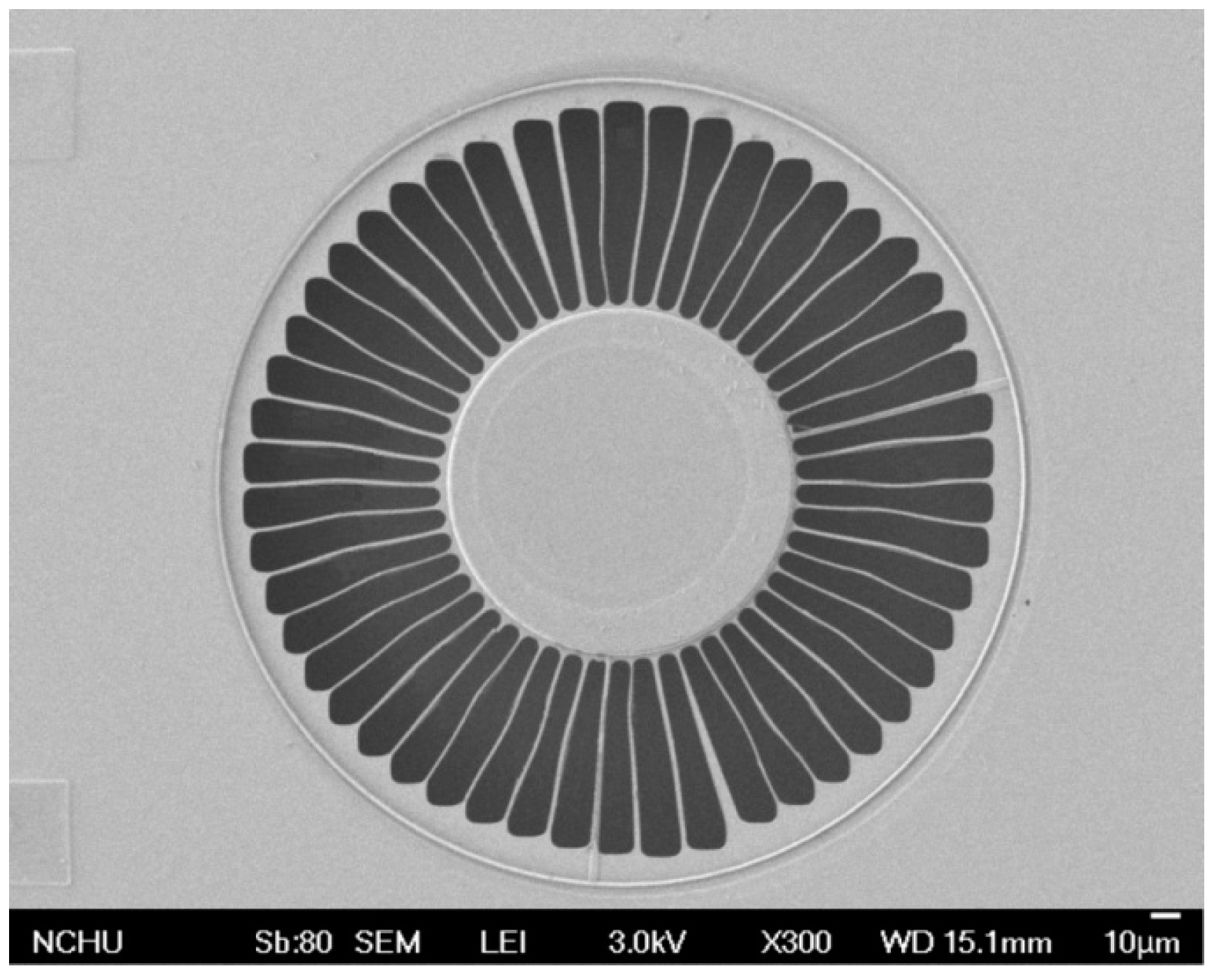
4. Results and Discussion

Figure 7 shows the measurement instruments for the thermoelectric energy harvester. A heater, a cooler, a multifunction electrical meter and an LCR (inductance capacitance resistance) meter were employed to test the performance of the thermoelectric energy harvester. The energy harvester was set on the cooler. The power supplier provided a power to the heater and cooler. The heater was used to generate a heat source to the thermoelectric energy harvester. The suspended part of the energy harvester was heated by the radiation heat source. The cooler was utilized to increase a heat sink for the cold part of the energy harvester. The LCR meter was adopted to measure the resistance of the energy harvester. The multifunction electrical meter was employed to record the output voltage of the energy harvester.
Figure 7. Measurement setup for the thermoelectric energy harvester.
Micromachines 06 01439 g007
The resistance of the thermoelectric energy harvester was measured by the LCR meter, and the measured results showed that the energy harvester had a resistance of 8 kΩ. The temperature difference between the hot and cold parts in the thermoelectric energy harvester was measured using an infrared thermometer. The output voltage of the thermoelectric energy harvester was detected by the multifunction electrical meter. Figure 8 reveals the measurement results of the output voltage for the thermoelectric energy harvester. The measured results showed that the thermoelectric energy harvester had an output voltage of 2.65 mV at the temperature difference of 10 K and an output voltage of 4 mV at the temperature difference of 15 K. The area of the thermoelectric energy harvester chip was about 1.5 mm2. The output voltage per area of the thermoelectric energy harvester was 0.178 mV·mm−2·K−1. A comparison to the simulated results in Figure 2, the measured output voltage of the energy harvester has an error percentage of about 5%.
Figure 8. Measured output voltage and power of the thermoelectric energy harvester.
Micromachines 06 01439 g008
The output voltage of the thermoelectric energy harvester was utilized to evaluate its output power. The resistance R = 8 kΩ and the measured output voltage in Figure 8 were substituted into Equation (2), the maximum output power of the thermoelectric energy harvester was obtained. Figure 8 depicts the maximum output power of the thermoelectric energy harvester. The results showed that the thermoelectric energy harvester had an output power of 0.22 pW at the temperature difference of 10 K and an output power of 0.5 pW at the temperature difference of 15 K. The power factor of the thermoelectric energy harvester was 1.47 × 10⁻³ pW·mm−2·K−2.
Kao et al. [18] employed the CMOS-MEMS process to manufacture a thermoelectric micro generator. The output voltage per area of the micro generator was 0.093 mV·mm−2·K−1, and its power factor was 6.4 × 10⁻⁷ μW·mm−2·K−2. Kouma et al. [17] developed a thermoelectric micro generator with high aspect ratio thermocouples. The measured results showed that the thermoelectric generator had an output voltage per area of 0.16 V·cm−2·K−1 and an output power factor of 9.3 μW cm−2·K−2. A comparison to Kao et al. [18], the output power factor in this work exceeds that of Kao et al. [18] because the thermocouple number per area in this work is increased.

5. Conclusions

A thermoelectric energy harvester has been manufactured using the commercial CMOS process. The thermoelectric energy harvester consisted of eight energy harvesting cells, and each harvesting cell contained 25 thermocouples in series. The thermocouples were made of p-type and n-type polysilicons. The output power of the energy harvester depended on the number of the thermocouples. To enhance the output power, the thermocouple number per area was increased. The energy harvester required a post-process to release the suspended plat of hot part. The post-process used CHF3/O2 RIE to etch the sacrificial silicon dioxide layer and utilized XeF2 RIE to etch the silicon substrate. The experimental results showed that the thermoelectric energy harvester had an output voltage of 4 mV at the temperature difference of 15 K, and its output voltage per area was 0.178 mV·mm−2·K−1. Owing to increase the thermocouple number per area, the output power factor in this work exceeds that of Kao et al. [18]. The thermoelectric energy harvester is suitable for application in portable electronic devices as an auxiliary electrical power source.

Acknowledgments

The authors would like to thank National Center for High-performance Computing (NCHC) for chip simulation; National Chip Implementation Center (CIC) for chip fabrication and the National Science Council of the Republic of China for financially supporting this research under Contract No MOST 104-2221-E-005-029-MY2.

Author Contributions

Shih-Wen Peng carried out the design and fabrication of the thermoelectric energy harvester and measured its characterization. Po-Jen Shih simulated and analyzed the performance of the energy harvester. Ching-Liang Dai supervised the work of Shih-Wen Peng and wrote the paper. All authors read and approved the final manuscript.

Conflicts of Interest

The authors declare no conflict of interest.

References

  1. Elefsiniotis, A.; Samson, D.; Becker, T.; Schmid, U. Investigation of the performance of thermoelectric energy harvesters under real flight conditions. J. Electron. Mater. 2013, 42, 2301–2305. [Google Scholar] [CrossRef]
  2. Davila, D.; Tarancon, A.; Calaza, C.; Salleras, M.; Fernandez-Regulez, M.; San Paulo, A.; Fonseca, L. Monolithically integrated thermoelectric energy harvester based on silicon nanowire arrays for powering micro/nanodevices. Nano Energy 2012, 1, 812–819. [Google Scholar] [CrossRef]
  3. Ibragimov, A.; Pleteit, H.; Pille, C.; Lang, W. A Thermoelectric energy harvester directly embedded into casted aluminum. IEEE Electron. Device Lett. 2012, 33, 233–235. [Google Scholar] [CrossRef]
  4. Thangaraj, K.; Elefsiniots, A.; Becker, Th.; Schmid, U.; Lees, J.; Featherston, C.A.; Pullin, R. Energy storage options for wireless sensors powered by aircraft specific thermoelectric energy harvester. Microsyst. Technol. 2014, 20, 701–707. [Google Scholar] [CrossRef]
  5. Yang, S.M.; Cong, M.; Lee, T. Application of quantum well-like thermocouple to thermoelectric energy harvester by BiCMOS process. Sens. Actuators A Phys. 2011, 166, 117–124. [Google Scholar] [CrossRef]
  6. Dai, C.L.; Chang, Y.M. A resonant method for determining mechanical properties of Si3N4 and SiO2 thin films. Mater. Lett. 2007, 61, 3089–3092. [Google Scholar] [CrossRef]
  7. Su, J.; Vullers, R.J.M.; Goedbloed, M.; van Andel, Y.; Leonov, V.; Wang, Z. Thermoelectric energy harvester fabricated by Stepper. Microelectron. Eng. 2010, 87, 1242–1244. [Google Scholar] [CrossRef]
  8. Dai, C.L.; Kao, P.H.; Tai, Y.W.; Wu, C.C. Micro FET pressure sensor manufactured using CMOS-MEMS technique. Microelectron. J. 2008, 39, 744–749. [Google Scholar] [CrossRef]
  9. Gardner, J.W.; Varadan, V.K.; Awadelkarim, O.O. Microsensors, MEMS and Smart Devices; John Wiley & Sons Ltd.: Chichester, UK, 2001. [Google Scholar]
  10. Yadav, S.; Sharma, P.; Yamasani, P.; Minaev, S.; Kumar, S. A prototype micro-thermoelectric power generator for micro-electromechanical systems. Appl. Phys. Lett. 2014, 104, 123903. [Google Scholar] [CrossRef]
  11. Dai, C.L.; Hsu, H.M.; Tsai, M.C.; Hsieh, M.M.; Chang, M.W. Modeling and fabrication of a microelectromechanical microwave switch. Microelectron. J. 2007, 38, 519–524. [Google Scholar] [CrossRef]
  12. Yang, M.Z.; Dai, C.L.; Shih, P.J.; Chen, Y.C. Cobalt oxide nanosheet humidity sensor integrated with circuit on chip. Microelectron. Eng. 2011, 88, 1742–1744. [Google Scholar] [CrossRef]
  13. Su, J.; Leonov, V.; Goedbloed, M.; van Andel, Y.; de Nooijer, M.C.; Elfrink, R.; Wang, Z.; Vullers, R.J.M. A batch process micromachined thermoelectric energy harvester: Fabrication and characterization. J. Micromech. Microeng. 2010, 20, 104005. [Google Scholar] [CrossRef]
  14. Huesgen, T.; Woias, P.; Kockmann, N. Design and fabrication of MEMS thermoelectric generators with high temperature efficiency. Sens. Actuators A Phys. 2008, 145, 423–429. [Google Scholar] [CrossRef]
  15. Yu, X.; Wang, Y.; Liu, Y.; Li, T.; Zhou, H.; Gao, X.; Feng, F.; Roinila, T.; Wang, Y. CMOS MEMS-based thermoelectric generator with an efficient heat dissipation path. J. Micromech. Microeng. 2012, 22, 105011. [Google Scholar] [CrossRef]
  16. Yuan, Z.; Ziouche, K.; Bougrioua, Z.; Lejeune, P.; Lasri, T.; Leclercq, D. A planar micro thermoelectric generator with high thermal resistance. Sens. Actuators A Phys. 2015, 221, 67–76. [Google Scholar] [CrossRef]
  17. Kouma, N.; Nishino, T.; Tsuboi, O. A high-output-voltage micro-thermoelectric generator having high-aspect-ratio structure. J. Micromech. Microeng. 2013, 23, 114005. [Google Scholar] [CrossRef]
  18. Kao, P.H.; Shin, P.J.; Dai, C.L.; Liu, M.C. Fabrication and characterization of CMOS-MEMS thermoelectric micro generators. Sensors 2010, 10, 1315–1325. [Google Scholar] [CrossRef] [PubMed] [Green Version]
  19. Dai, C.L.; Chiou, J.H.; Lu, M.S.C. A maskless post-CMOS bulk micromachining process and its application. J. Micromech. Microeng. 2005, 15, 2366–2371. [Google Scholar] [CrossRef]
  20. Sun, C.M.; Tsai, M.H.; Liu, Y.C.; Fang, W. Implementation of a monolithic single proof-mass tri-axis accelerometer using CMOS-MEMS technique. IEEE Trans. Electron. Devices 2010, 57, 1670–1679. [Google Scholar] [CrossRef]
  21. Dai, C.L.; Chen, H.L.; Chang, P.Z. Fabrication of a micromachined optical modulator using the CMOS process. J. Micromech. Microeng. 2001, 11, 612–615. [Google Scholar] [CrossRef]
  22. Dennis, J.O.; Ahmed, A.Y.; Khir, M.H. Fabrication and characterization of a CMOS-MEMS humidity sensor. Sensor 2015, 15, 16674–16687. [Google Scholar] [CrossRef] [PubMed]
  23. Dai, C.L.; Chen, Y.C.; Wu, C.C.; Kuo, C.F. Cobalt oxide nanosheet and CNT micro carbon monoxide sensor integrated with readout circuit on chip. Sensors 2010, 10, 1753–1764. [Google Scholar] [CrossRef] [PubMed]
  24. Lee, K.Y.; Huang, J.T.; Hsu, H.J.; Chiu, M.C.; Tsai, T.C.; Chen, C.K. CMOS-MEMS piezoresistive force sensor with scanning signal process circuit for vertical probe card. Sens. Actuators A Phys. 2010, 160, 22–28. [Google Scholar] [CrossRef]
  25. Yang, M.Z.; Dai, C.L.; Wu, C.C. A zinc oxide nanorod ammonia microsensor integrated with a readout circuit on-a-chip. Sensors 2011, 11, 11112–11121. [Google Scholar] [CrossRef] [PubMed]
  26. Lu, C.C.; Huang, J. A 3-axis miniature magnetic sensor based on a planar fluxgate magnetometer with an orthogonal fluxguide. Sensors 2015, 15, 14727–14744. [Google Scholar] [CrossRef] [PubMed]
  27. Haris, M.; Qu, H.W. Fully differential CMOS-MEMS z-axis accelerometer with torsional structures and planar comb fingers. J. Micro-Nanolith. MEMS MOEMS 2010, 9, 013031. [Google Scholar] [CrossRef]
  28. Dai, C.L.; Lu, P.W.; Wu, C.C.; Chang, C. Fabrication of wireless micro pressure sensor using the CMOS process. Sensors 2009, 9, 8748–8760. [Google Scholar] [CrossRef] [PubMed]
  29. Yang, M.Z.; Dai, C.L.; Lin, W.Y. Fabrication and characterization of polyaniline/PVA humidity microsensors. Sensors 2011, 11, 8143–8151. [Google Scholar] [CrossRef] [PubMed]
  30. Xie, J.; Lee, C.; Feng, H. Design, fabrication, and characterization of CMOS MEMS-based thermoelectric power generators. J. Microelectromech. Syst. 2010, 19, 317–324. [Google Scholar] [CrossRef]
  31. Strasser, M.; Aigner, R.; Lauterbach, C.; Sturm, T.F.; Franosch, M.; Wachutka, G. Micromachined CMOS thermoelectric generators as on-chip power supply. Sens. Actuat. A Phys. 2004, 114, 362–370. [Google Scholar] [CrossRef]
  32. Sato, N.; Kuwabara, K.; Ono, K.; Sakata, T.; Morimura, H.; Terada, J.; Kudou, K.; Kamei, T.; Yano, M.; Machida, K.; et al. Monolithic integration fabrication process of thermoelectric and vibrational devices for microelectromechanical system power generator. Jpn. J. Appl. Phys. 2007, 46, 6062–6067. [Google Scholar] [CrossRef]
  33. Dai, C.L.; Xiao, F.Y.; Juang, Y.Z.; Chiu, C.F. An approach to fabricating microstructures that incorporate circuits using a post-CMOS process. J. Micromech. Microeng. 2005, 15, 98–103. [Google Scholar] [CrossRef]
  34. Kao, P.H.; Dai, C.L.; Hsu, C.C.; Lee, C.Y. Fabrication and characterization of a tunable in-plane resonator with low driving voltage. Sensors 2009, 9, 2062–2075. [Google Scholar] [CrossRef] [PubMed]
  35. Chang, C.; Lee, C.Y.; Shih, W.P.; Dai, C.L. Wet etching rates of InGaZnO for the fabrication of transparent thin-film transistors on plastic substrates. Thin Solid Film 2010, 518, 3992–3998. [Google Scholar]
  36. Dai, C.L.; Xiao, F.Y.; Lee, C.Y.; Cheng, Y.C.; Chang, P.Z.; Chang, S.H. Thermal effects in PZT: Diffusion of titanium and recrystallization of platinum. Mater. Sci. Eng. A 2004, 384, 57–63. [Google Scholar] [CrossRef]

