3.1. Thermal Analysis
In this section, a beam (
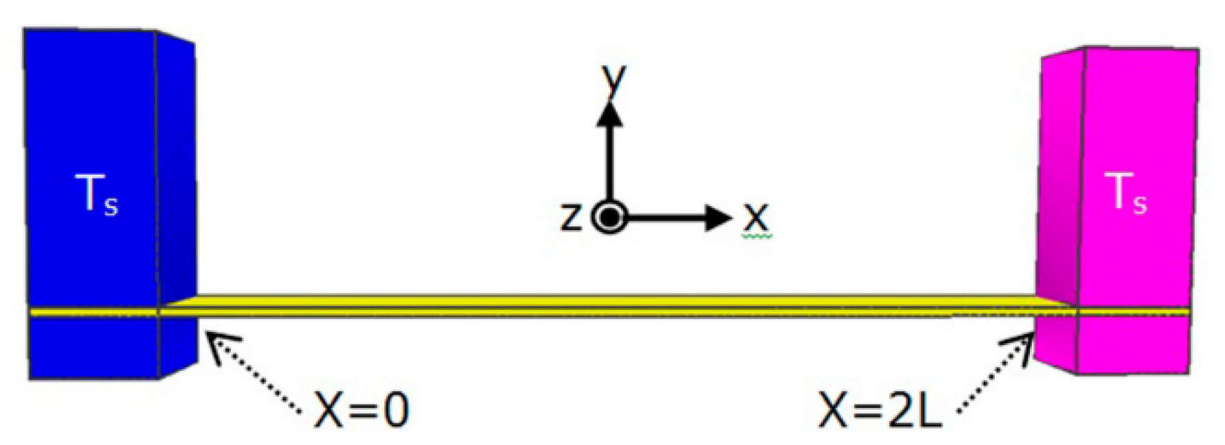
Figure 2) is analyzed in terms of its electro-thermal properties. In this single beam, when the temperature is different between the ambient temperature and the inside of the beam, the change in the length of the beam can be given by [
8,
9]:
where α(
T) is the thermal expansion coefficient and is constant for various temperatures. This equation can be simplified as follows:
Figure 2.
Conventional single beam with length 2L connected to pads with ambient temperature Ts.
Figure 2.
Conventional single beam with length 2L connected to pads with ambient temperature Ts.
By applying a voltage across the beam, the electrical energy, as a function of current
I and resistance
R, is converted to thermal energy, which induces thermal expansion:
Before determining the change in the beam and the force generated (in the next section), we should consider the temperature distribution within the beam using the following equation:
where
kT,
J and ρ are the thermal conductivity, current density and resistivity of the beam, respectively. Both resistivity ρ and thermal conductivity
kT change with temperature. Assuming
kT is a constant and the resistivity of the beam changes linearly as the temperature varies,
kT is assumed to be equal to the thermal conductivity at room temperature, and:
where ρ
0 is the resistivity at
Ts (ambient or surrounding temperature) and λ is the linear temperature coefficient. Equation (5) can be written as follows:
The solution to this differential equation is a combination of a homogeneous term and a non-homogenous constant. According to
Figure 2 and using the initial conditions
T(
x = 0 and
x = 2
L) =
Ts, the final solution to Equation (6) with
can be obtained as follows:
Now, the average temperature in the beam is given by
Thus, by substituting Equation (7) into Equation (8), the average temperature can be obtained as follows:
As previously mentioned and according to
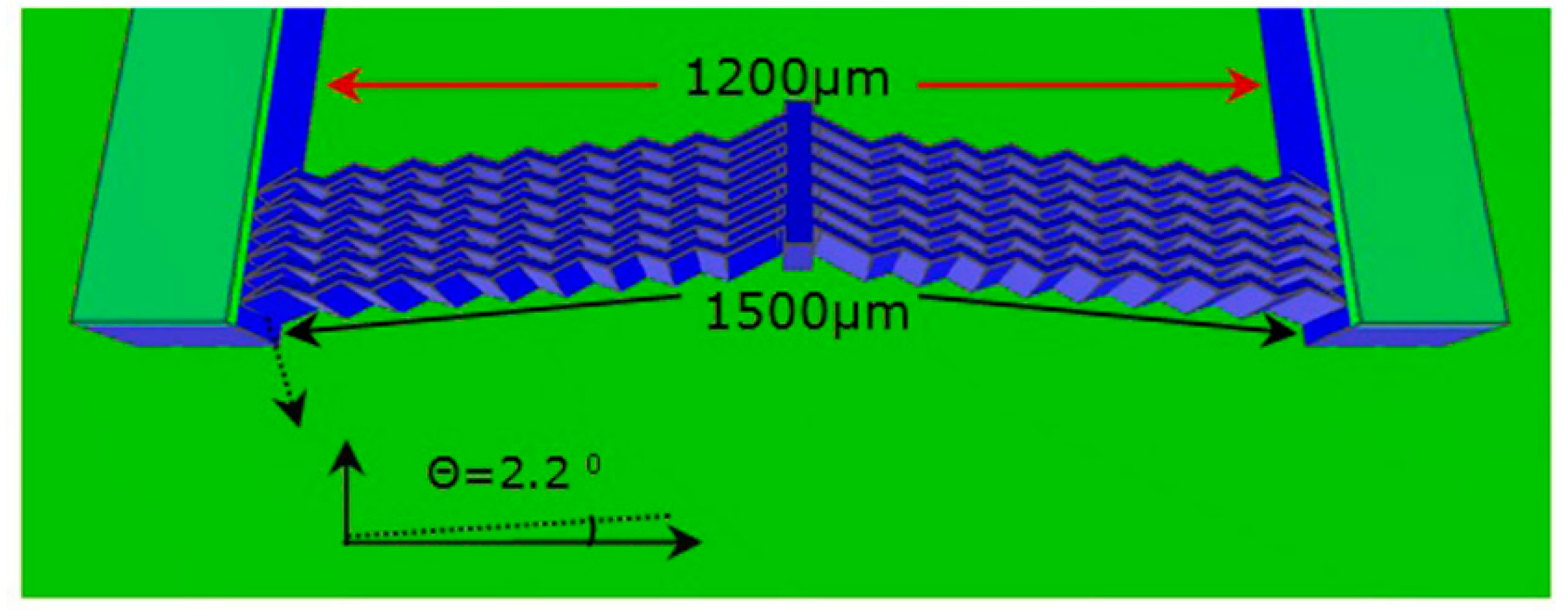
Figure 3, in our integrated structure, there are six spring chevron beams on either side of the center shaft. With a direct distance of 1200 μm, the beams measure 1500 μm in length with a cross-sectional area of 10 μm × 100 μm and a rib angle of 2.2°. The properties of the silicon substrate and the details of the micropump structure are summarized in
Table 1.
Figure 3.
Six spring chevron beams measuring 1500 μm in length with a cross-sectional area of 10 μm × 100 μm and a rib angle of 2.2°.
Figure 3.
Six spring chevron beams measuring 1500 μm in length with a cross-sectional area of 10 μm × 100 μm and a rib angle of 2.2°.
Table 1.
Material properties of silicon wafer and detailed design of proposed structure.
Table 1.
Material properties of silicon wafer and detailed design of proposed structure.
| Length of beams l = 2L | Applied voltage V | Current density J | Resistivity ρ0 | Linear temperature coefficient [10] λ | Thermal conductivity [11,12,13] kT | Ambient temperature Ts | |
|---|
| 1500 μm | 8 V | 5.1 × 10³ A/cm2 | 0.01 ohm-cm | 1.25 × 10⁻⁴ /°C | 1.57 W/cm-°C | 27 °C | 4.5 cm−1 |
According to Ohm’s law and the relations
I =
J·
A,
R = ρ
l/
A and
J =
I/
A =
V/ρ
l, and based on the details presented in
Table 1, solving Equations (7) and (9) in MATLAB yields the following maximum and average temperatures
Tmax and
Tavg, respectively:
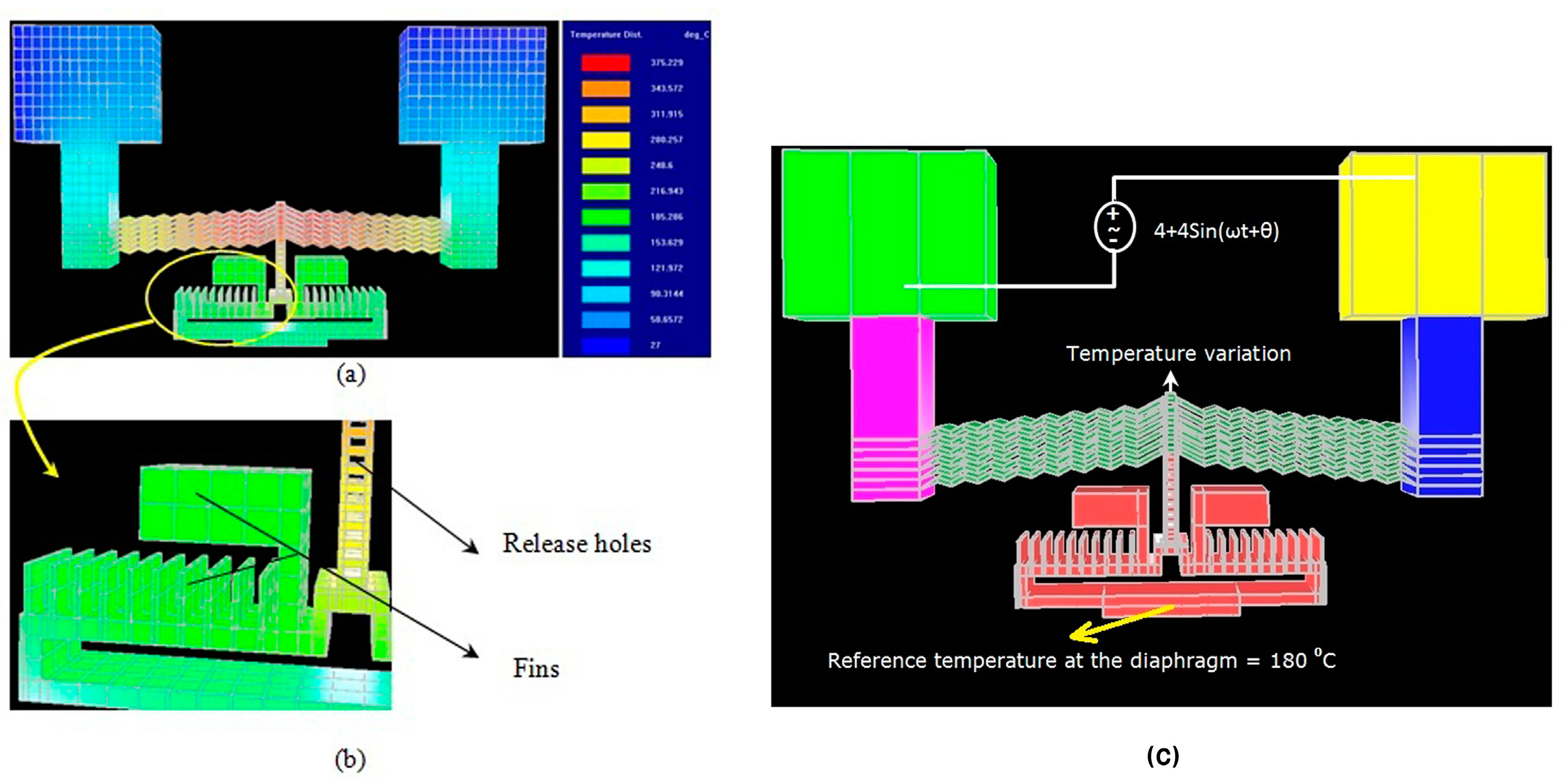
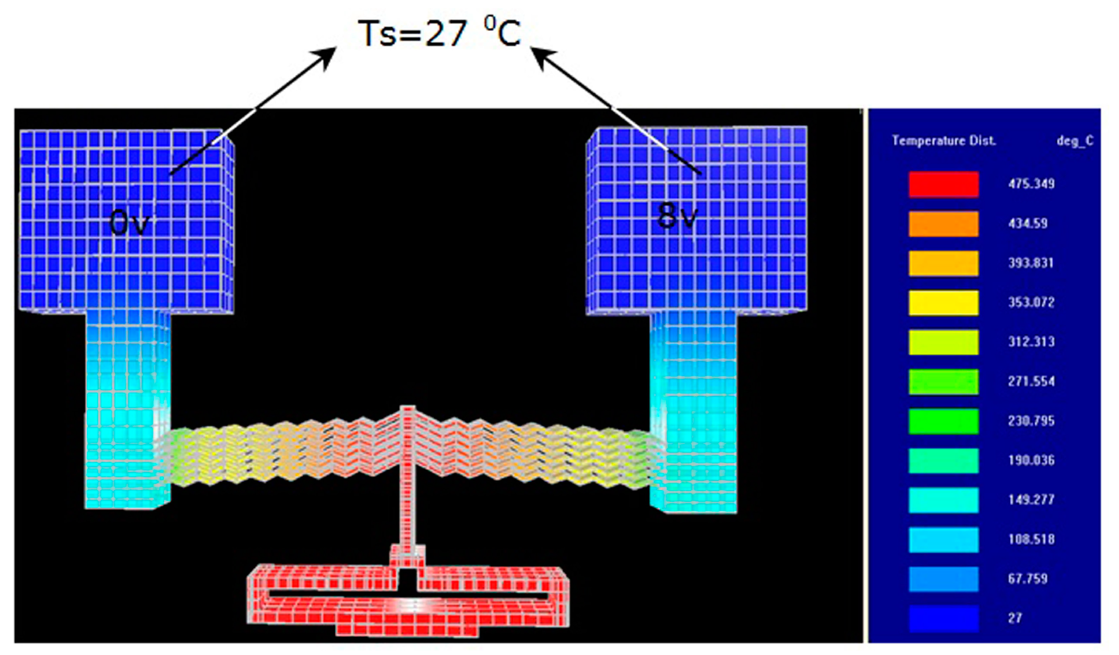
We used the IntelliSuite software program to analyze the static and dynamic behaviors of the proposed structure and visualize the results.
(1) In the static analysis, the structure (half die) was analyzed using the IntelliSuite software program. On the voltage pads, constant temperature (27 °C) boundary conditions were defined. The voltage on one of the pads was fixed at 0 V, whereas on the other pad, a voltage of 8 V was applied. This structure was designed using Intellimask (IntelliSuite, Woburn, MA, USA) and 3D Builder modules and later imported into the thermo-electro-mechanical module. Appropriate materials properties were defined, and the structure was then meshed with a maximum mesh size of 40 μm to generate approximately 18,604 elements.
The simulation results presented in
Figure 4 show the maximum temperature attained in this case. A rise in the temperature of the device above the ambient temperature is a result of Joule heating occurring in the chevron beams. As previously mentioned, when a differential voltage is applied to the pads, the narrower section of the pump structure (chevron beams measuring 10 μm wide) develops a higher resistance to current than the rest of the structure (voltage pads).
Figure 4.
Geometry and boundary conditions of the proposed structure with simulation results obtained for temperature distribution (for half device only).
Figure 4.
Geometry and boundary conditions of the proposed structure with simulation results obtained for temperature distribution (for half device only).
As a result, the power (square of the current times the resistance of the beams) is dissipated in the narrower section, causing it to expand due to induced thermal strain (Joule heating). Because all the beams are identical, the resistance through the beams will be the same, resulting in uniform heating; furthermore, because symmetrical temperature boundary conditions exist, a uniform temperature distribution is also created. Therefore, the maximum temperature is obtained in the center shaft and is equal to 475.5 °C, which is similar to the result, obtained using Equation (10).
Specifically, the maximum temperature was noted at the intersection of the chevron beams and the center shaft. Therefore, the pump cannot be used for its intended application in its present form. The potency and stability of medical drugs are known to degrade at such high temperatures, which might create a problem by changing the sensitive fluid properties in the micropump flow path.
To solve this problem, we proposed certain design modifications to reduce the heat flow and temperature distribution at the flow path while maintaining the high temperature at the
V beams to create greater displacement:
One of the viable options is to optimize the air gap underneath and above the device, which would help locally increase the temperature of the chevron beams alone and not that of the pumping diaphragm (that is in contact with the pumping fluid). Thus, in ongoing research, the air gap plays a crucial role in determining the temperature of the chevron beams. From the chevron beams, heat is initially conducted to the air gap (2 μm) underneath and (2 μm) above the device and then to the handle layer and top plate layer. According to
Figure 5a, the boundary conditions on the voltage pads are similar to those shown in
Figure 4. In addition, the boundary condition of heat convection was defined on the bottom and top of the device layer. The structure was meshed with a maximum mesh size of 40 μm to generate approximately 18,604 elements. The simulation results presented in
Figure 5a,b illustrate a maximum temperature of 375 °C at the center shaft, an average temperature of 260 °C and a temperature of 180 °C at the pump diaphragm for the same input voltage used to generate the results shown in
Figure 4.
We developed another design by providing fins and release holes in the back of the diaphragm and center shaft, respectively (
Figure 5b). The addition of fins and etching holes throughout the central rod provide a significant reduction in temperature. This design reduces the temperature of the center shaft and pump diaphragm by approximately 10 °C.
Although the temperatures obtained in the previous section (i) are still higher than the sustainable limits of medical drugs, the temperature at the contact point (i.e., at the diaphragm) is slightly above the ambient temperature.
Inserting a polymer tube (as an insulator) not only solves the high-temperature problem at the contact of the pump diaphragm but also allows for a higher temperature at the center shaft and thus greater displacement. A biocompatible polymer (such as Parylene) was used as a tube material because it can be conformably deposited and patterned [
14,
15]. Thus, we can use a Parylene tube as an insulating thermoplastic coating on the diaphragm, which prevents heat transfer to the fluid flow and transfers the force and motion of the thermal actuators to the fluid. (The fabrication details of the Parylene tube and the added benefit of eliminating leakage problems will be described in
Section 3.1). As previously mentioned, the temperature at the pump diaphragm was significantly reduced to 180 °C, which is below the melting temperature of Parylene (290 °C).
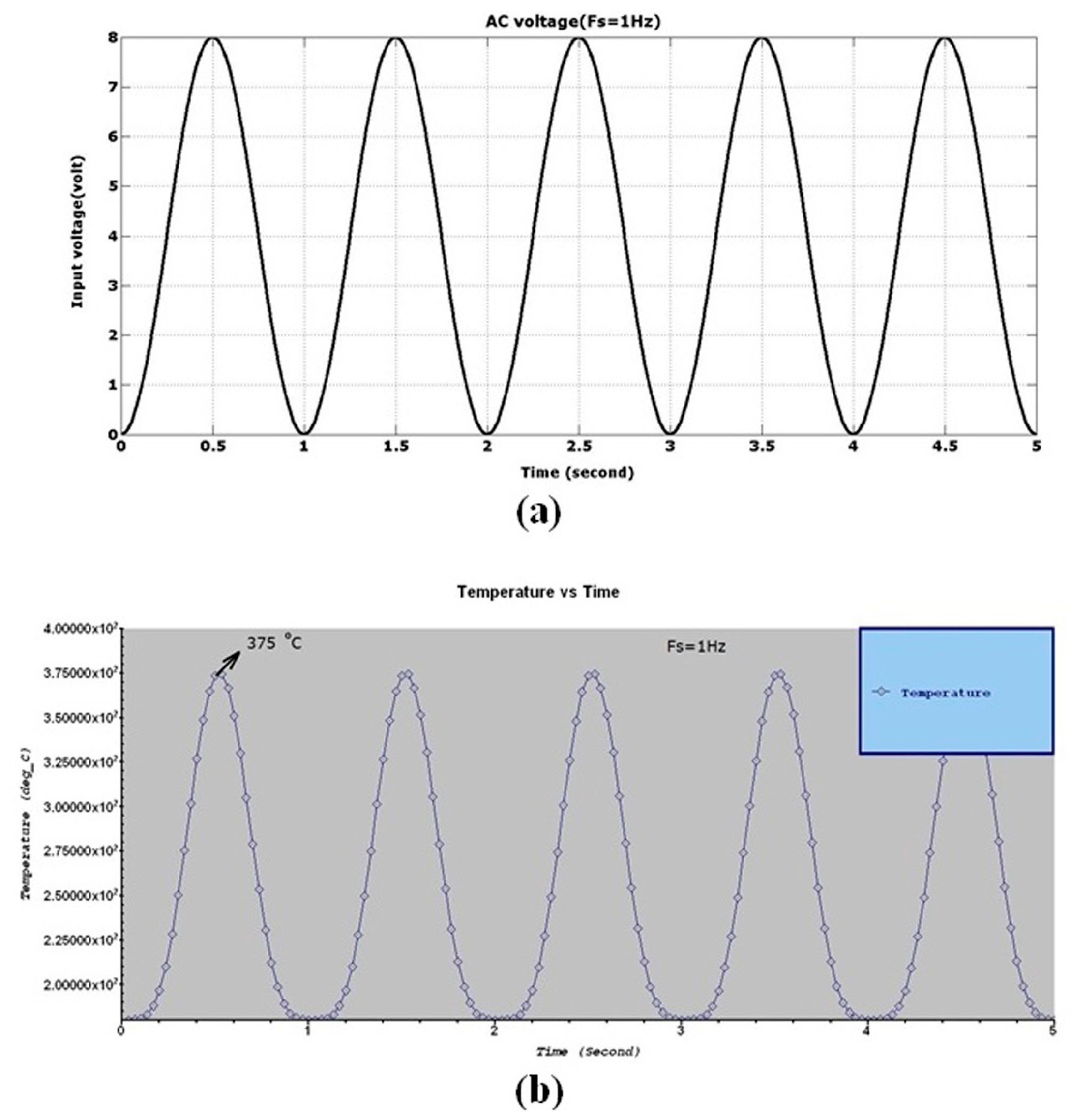
(2) In the dynamic analysis, we analyzed the operation of the structure at different frequencies of the applied input voltage. In this case, we used the thermo-electro-mechanical module to visualize the simulation results obtained for a temperature variation in the center shaft and its dynamic behavior as a function of different applied frequencies. As shown in
Figure 5c, we applied a reference temperature of 180 °C to the pump diaphragm (obtained in
Figure 5a) instead of convective boundary conditions. Moreover, we applied an AC voltage with an amplitude of 8 V and different frequencies in the range of 1–400 Hz.
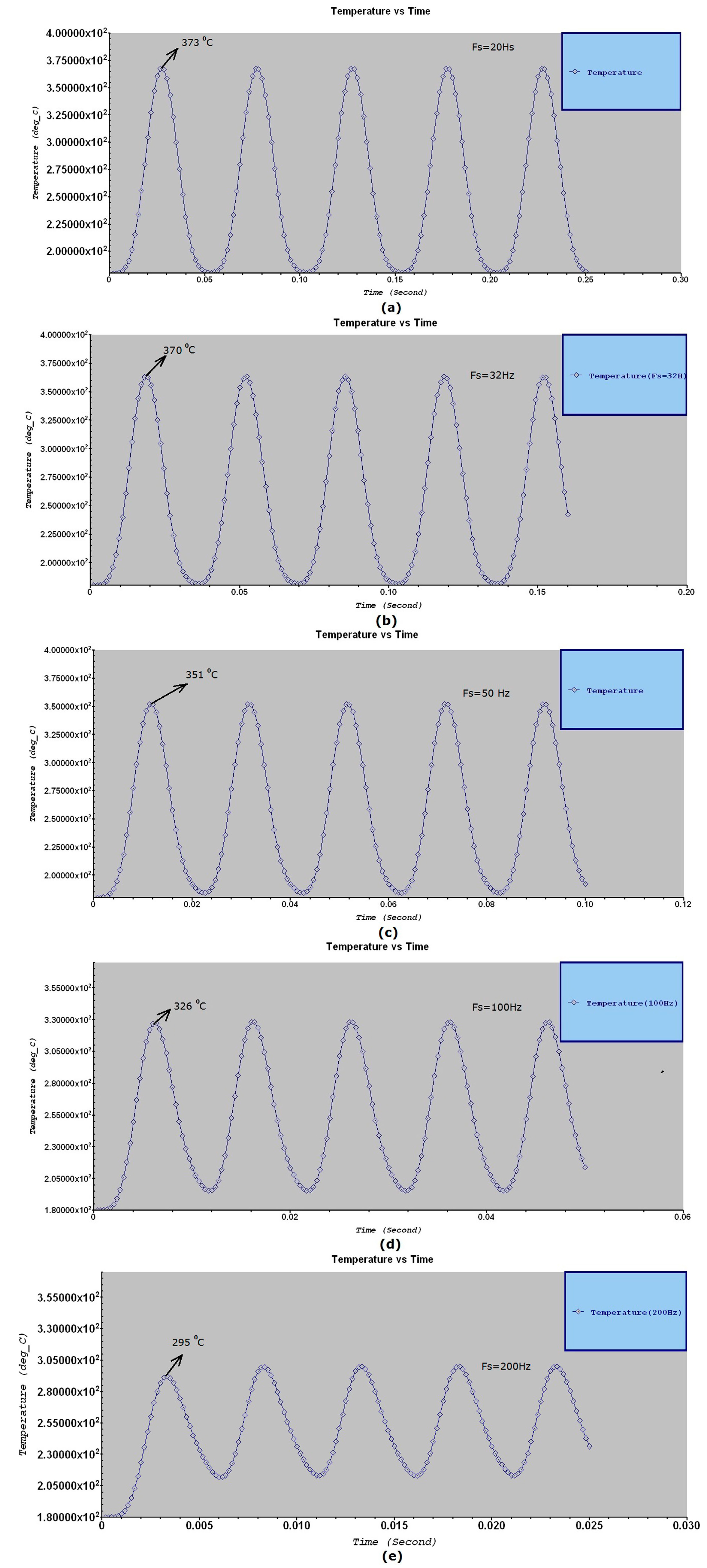
According to
Figure 6 and
Figure 7, the simulation results show that in the frequency range of 1–32 Hz, the maximum temperature of the center shaft is constant at a value of approximately ~375 °C, determined with an accuracy of 99% (~5 °C error), whereas in the other frequency ranges, the waveforms are destroyed. According to
Table 2, the temperature is not constant and will decrease. Thus, in this study, the frequency range 1–32 Hz is considered acceptable.
In contrast to conventional electro-thermal actuator designs, which require higher voltages and introduce higher temperatures, our structure is simpler and uses a lower voltage (8 V) over suitable frequencies. The design also keeps the diaphragm cool to avoid heat flow and to prevent any changes in fluid properties [
9,
16].
Figure 5.
Temperature distribution (Tmax of center shaft is 375 °C, average temperature is 260 °C and pump diaphragm temperature is 180 °C) of modified structure with (a) boundary conditions of heat convection and (b) fins added to the back of the diaphragm and holes etched in the center shaft. (c) Applying AC voltage to the proposed structure to demonstrate dynamic behavior.
Figure 6.
Dynamic behavior of the structure shown in
Figure 5c: (
a) Input voltage applied with a frequency of
f = 1 Hz. (
b) Temperature variation in the center shaft (max Temperature = 375 °C).
Figure 6.
Dynamic behavior of the structure shown in
Figure 5c: (
a) Input voltage applied with a frequency of
f = 1 Hz. (
b) Temperature variation in the center shaft (max Temperature = 375 °C).
Figure 7.
Temperature variation of the center shaft shown in
Figure 5c: (
a) Max Temperature = 373 °C with
f = 20 Hz. (
b) Max Temperature = 370 °C with
f = 32 Hz. (
c) Max Temperature = 351 °C with
f = 50 Hz. (
d) Max Temperature = 326 °C with
f = 100 Hz. (
e) Max Temperature = 295 °C with
f = 200 Hz.
Table 2.
Temperature variation of the center shaft versus frequency of applied voltage.
Table 2.
Temperature variation of the center shaft versus frequency of applied voltage.
| Frequency (Hz) | 1 | 5 | 10 | 20 | 32 | 50 | 100 | 200 | 300 | 400 |
| Temperature (°C) | 375 | 375 | 375 | 373 | 370 | 351 | 326 | 295 | 269 | 250 |
3.2. Pumping Force Analysis
To determine the flow rate of the micropump, it is necessary to estimate the pumping force. When a voltage is applied to the pads, the chevron beams will expand due to Joule heating, which will move the diaphragm and exert a force on the fluid. The maximum force is given by [
17],
where
F is the force at the actuator,
A is the cross-sectional area of the beam and σ is the coefficient of thermal expansion. Because the strain ε is given by ε(
x) = α
T(
x) and the axial stress σ with Young’s modulus
E is given by σ =
Eε, using Equations (2) and (8), the force developed by the actuator with beam springy length
l = 2
L is given by,
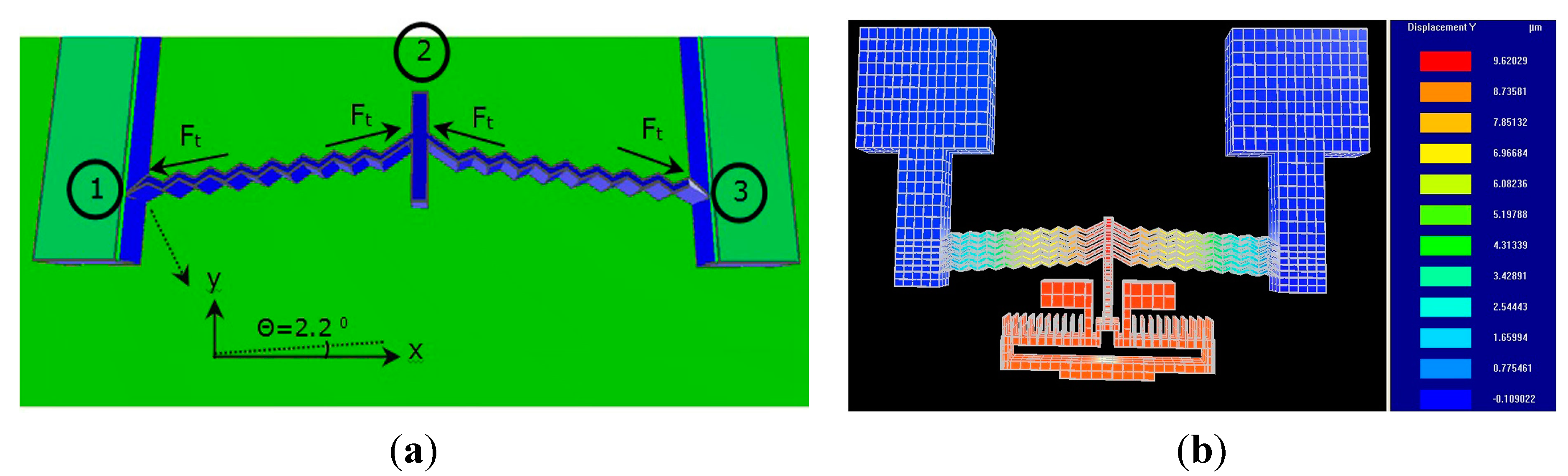
According to
Figure 8a, to obtain a more accurate calculation and because the beam is designed with a rib angle of 2.2°, it is necessary to analyze the force obtained to balance all forces. At points 1 and 3, the resultant force is absorbed by the fixed pad wall. Along the
x direction of node 2,
and along the
y direction,
For
N chevron beams, the total force is:
Figure 8.
(a) Diagram of forces acting on a chevron beam (V form). (b) Simulation results of obtained displacement (9.6 μm) of pump diaphragm.
Figure 8.
(a) Diagram of forces acting on a chevron beam (V form). (b) Simulation results of obtained displacement (9.6 μm) of pump diaphragm.
According to
Figure 5a (
Tavg = 260 °C) and using Equation (12) with θ = 2.20,
L = 750 μm and data listed in
Table 3, we obtained the following value,
and the total force in the
y direction for 6 beams will be,
In addition,
Figure 8b shows that the resulting displacement of the pump diaphragm is approximately 9.6 μm.
In contrast to the design described in a previous study [
16], our structure with a beam springy length
L = 750 μm uses a lower voltage of 8 V. The obtained force is also several times higher than that obtained in comb drive structures [
18,
19].
Table 3.
Material properties of silicon in the chevron beams.
Table 3.
Material properties of silicon in the chevron beams.
| Cross sectional of beams A | Young’s Modulus E | Coefficient of thermal expansion α | number of chevron beams N |
|---|
| 1 × 10⁻⁵ cm2 | 169 × 105 N/cm2 | 2.9 × 10⁻⁶ K−1 | 6 |
3.3. Flow Rate Analysis
To estimate the flow rate of a pump with a nozzle/diffuser arrangement, the pressure loss through the nozzle/diffuser must be determined. The pressure loss depends on the inlet area of the nozzle and the exit area of the nozzle. However, we can still estimate the maximum flow rate (for the corresponding force) by replacing the nozzle/diffuser arrangement with check valves. For opening and closing the inlet and outlet of the fluid channel, we proposed and used check valves with a spring mode structure. Cheng and Tseng designed check valves using a spring design called the compliant orthoplanar spring [
20]. Each check valve consisted of a 1 mm circular plate suspended on four bridge springs. Similarly, as shown in
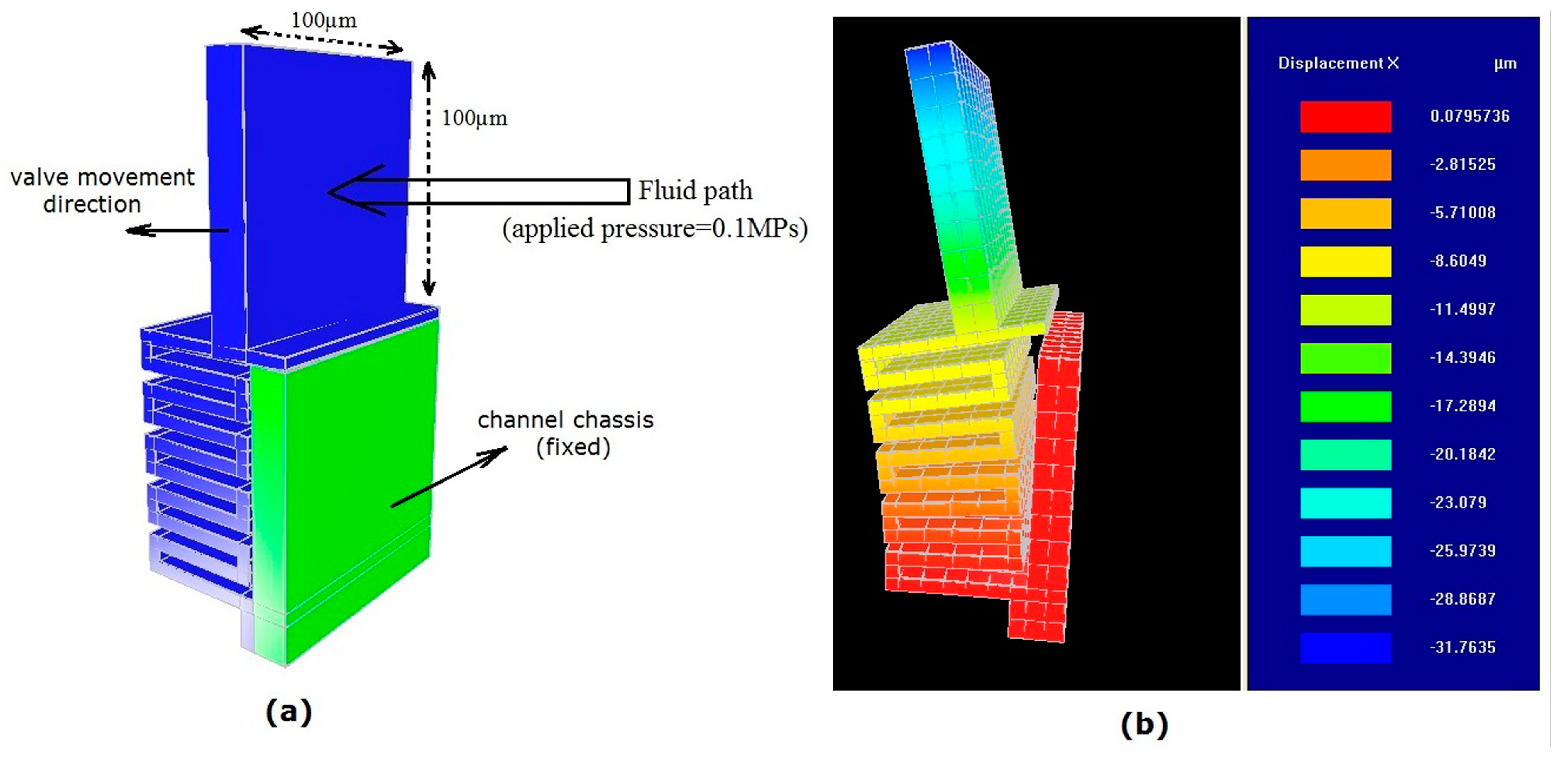
Figure 9a, our structure has a 100 μm × 100 μm movable area and is fixed and connected via a spring beam to the channel chassis (one bridge).
The simulation results show that a pressure of 0.1 MPa with a 1 mN pumping force (according to the pressure equation P = F/A) is needed to open/close the fluid channel to displace the check valve by approximately 31.7 μm.
Figure 9.
(a) Geometry of proposed check valve. (b) Simulation result showing 31.7 μm displacement with an applied 1 mN pumping force.
Figure 9.
(a) Geometry of proposed check valve. (b) Simulation result showing 31.7 μm displacement with an applied 1 mN pumping force.
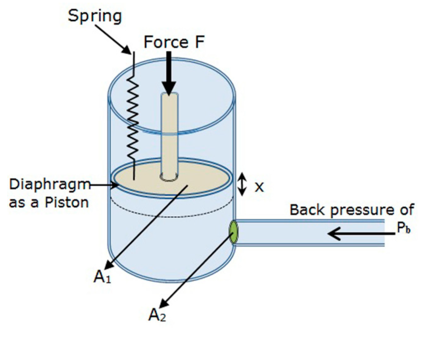
To estimate the flow rate of the pump based on the obtained force of 3.4 mN (calculated by subtracting 1 mN force dissipation from 4.4 mN total force), the pump system can be modeled as a piston moving in a cylindrical vessel with a pipe attached to the bottom (
Figure 10). The previously described micropump (
Figure 1) essentially consisted of a diaphragm and a nozzle/diffuser arrangement. For the device to operate as a pump, an AC voltage with frequency of 1–32 Hz is applied to the pads. For half of the cycle, the diaphragm deflects and pumps the fluid through the exit channel. For the other half of the cycle, the diaphragm returns to its initial position, during which fluid is siphoned through the inlet channel. Thus, the diaphragm exerts a periodic force F on the fluid.
Figure 10.
Piston-cylinder model of micropump with inlet/outlet.
Figure 10.
Piston-cylinder model of micropump with inlet/outlet.
According to
Figure 10, the piston moves through the cylinder, which has the same volume as the pump chamber. A damping factor was introduced to make the system critically damped, thereby removing oscillations in the system. Thus, by introducing the damping term and creating a lumped parameter model of the system, the force balance equation of the model is,
where
x is the displacement of the piston,
b is the damping factor (2
) required to remove oscillations in the system,
m is the mass of the piston,
k is the spring constant,
p1 is the pressure below the piston, A
1 is the cross-sectional area of the piston, and F is the force acting on the piston. To determine the final differential equation, we use the Bernoulli and Darcy-Weisbach equations (for a liquid such as insulin) [
21]:
where
is the outlet flow velocity,
is the density of the liquid,
is the pipe friction coefficient,
D is the diameter and
p2 is the outlet pressure. The outlet pressure should be able to overcome the pressure drop across the catheter (Δ
p) and the back pressure (
pb):
The resulting dynamic Equation (18) for the micropump takes the form of a nonlinear lumped model approximation of an ordinary differential equation (ODE):
Using a volumetric equation (
), the final differential equation will be,
Equation (23) is the governing equation for the exit and inlet channels of the pump.
Table 4 summarizes the nomenclatures and the values for the terms in Equation (23). This equation states the correlation between the fluid displaced by the pump and different parameters such as the geometry of the pump, mass of the diaphragm, applied force, stiffness
k (calculated as a ratio of the force to the displacement), and frequency of the applied force (
Table 4).
Table 4.
Nomenclature of value parameters used in Equation (23) for solving with MATLAB software.
Table 4.
Nomenclature of value parameters used in Equation (23) for solving with MATLAB software.
| Density of silicon d | Mass of Diaphragm m | Stiffness of diaphragm k | Back pressure pb | Density of fluid (insulin) ρl | Area of piston A1 | Area of outlet A2 | Force of actuator F |
|---|
| 2.3 g/cm3 | 8.6 μg | 354 N/m | 8 mm hg | 1 g/cm3 | 750 × 100 μm2 | 100 × 100 μm2 | 3.4 mN |
The obtained differential Equation (23) was evaluated and solved by numerical methods in MATLAB (ode45) to determine the flow rate of a liquid given by Equation (24). By applying a sinusoidal voltage, the value of the input force F takes the form F sin(ωt), where the term ω is the angular frequency of the input voltage.
As previously mentioned and according to the
Table 2, a sinusoidal input voltage with an amplitude of 8 V and maximum frequency of 32 Hz can be applied to our structure and can be used to solve Equation (23).
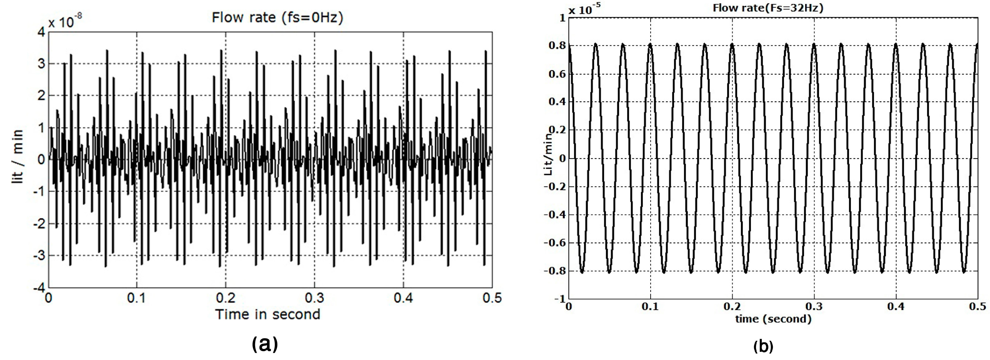
Figure 11 shows the simulation results of the estimated flow rate of the micropump obtained using Equation (24). With minimum and maximum frequencies of 0 and 32 Hz, respectively, the obtained flow rate will be approximately ~0 and 8 μL/min for half of the proposed die structure. Because we have a symmetrical structure, the maximum flow rate will be approximately 16 μL/min.
Figure 12 shows the simulation results obtained for various flow rates of the proposed micropump
versus the applied frequency. The figure suggests good performance and linearity up to 32 Hz.
Figure 11.
(a) Flow rate obtained at ~0 μL/min with dynamic behavior and fs = 0 Hz. (b) Flow rate obtained at ~8 μL/min (half die) with dynamic behavior and fs = 32 Hz.
Figure 11.
(a) Flow rate obtained at ~0 μL/min with dynamic behavior and fs = 0 Hz. (b) Flow rate obtained at ~8 μL/min (half die) with dynamic behavior and fs = 32 Hz.
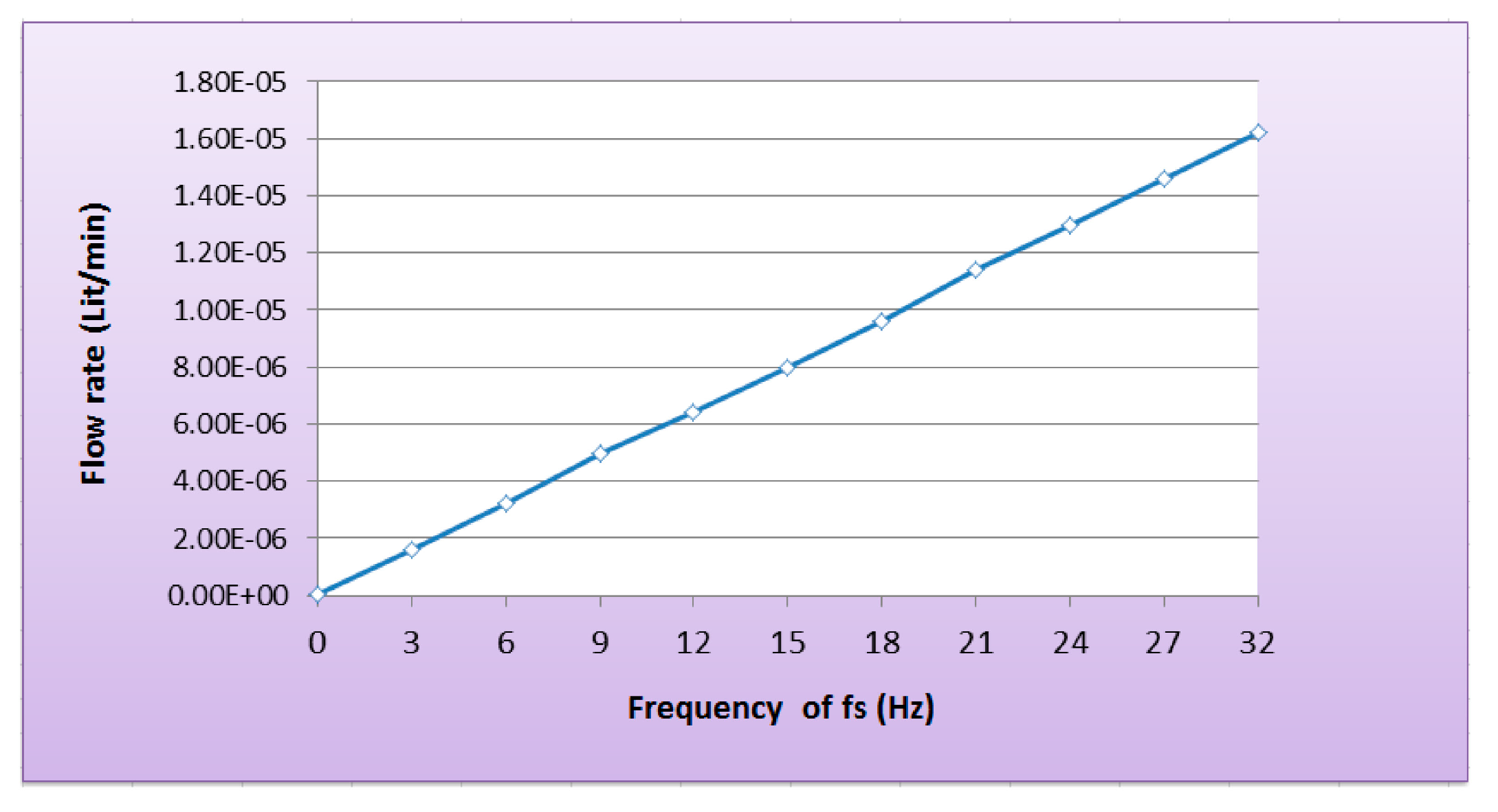
Figure 12.
Flow rate (0–16 μL/min) versus applied frequency (0–32 Hz).
Figure 12.
Flow rate (0–16 μL/min) versus applied frequency (0–32 Hz).
This result is highly intuitive because the flow rate depends on the force, which in turn depends on the average temperature of the chevron beams and, finally, the frequency of the sinusoidal input voltage. The flow rate depicted in
Figure 11b is the maximum delivery that can be achieved for the proposed in-plane micropump with good linearity over the frequency range of 0–32 Hz (
Figure 12). It is evident that the obtained flow rate is high and can be linearly controlled with an applied frequency, in contrast to designed described in previous studies [
6,
22].
3.4. Fluid Flow Leakage
As mentioned previously, to accommodate the motion of the moving parts in the pump layer (i.e., actuator, diaphragm, and check valves), a micron-sized gap was provided up and down the pump with a glass plate and handle layer, respectively. This design gave rise to some performance issues related to fluid leakage through this 2 μm gap. The flow path of the fluid was from the inlet valve through the pump chamber and towards the outlet through the outlet valve. The fluid was pressurized in the pump chamber by the in-plane motion of the diaphragm. Thus, the majority of the fluid would move towards the outlet valve, but due to the gap provided between the pump die and the top cover plate and bottom handle layer, some fluid would also leak through this gap.
Thus, it had to be ensured that the fluid would avoid the electro-thermal actuator (its temperature of 180 °C) and the electrical connections to operate the pump. Reducing the size of the gap was not an option because it would have stalled or limited the motion of the moving diaphragm due to friction. The actual physical separation of the fluid from the pump structure was concluded to be the best option. This separation could be achieved by enclosing the fluid in a type of flexible tube running between the vibrating actuators [
14,
15]. Parylene was used as a suitable material for this type of tube structure. Due to its physical properties and low Young’s modulus (3 GPa, which is approximately 60 times less than that of silicon), Parylene exhibits excellent mechanical properties,
i.e., high tensile and yield strength, biocompatibility, ease of manufacturing and sufficient deformation under small loads.
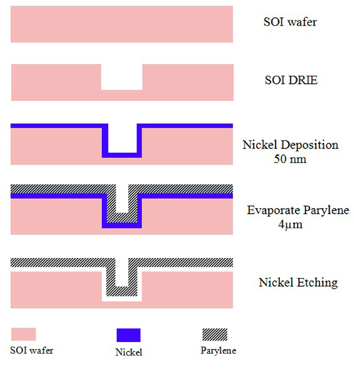
A special technique for manufacturing enclosed Parylene microchannels was used in this study. Parylene is deposited on a mold and on a flat surface. The molded Parylene is released from the mold and bonded to the flat Parylene layer, forming a free-standing, tube-like structure.
According to the process suggested (in
Figure 13), Parylene can be evaporated over a deep reactive-ion etching (DRIE) silicon mold already deposited with a layer of nickel or oxidized silicon to form a layer of silicon dioxide. This nickel or oxide layer is then etched away using the appropriate chemical agents.
The reasons for using a polymer tube as a covering for the pump chamber are as follows:
The tube not only fits into the narrow, trench-like structure in between the silicon V-beam actuators but also prevents contact between the fluid and the silicon actuators and prevents fluid leakage.
The tube serves as an insulating material that prevents the transmission of heat from the thermal actuators to the enclosed fluid.
Figure 13.
Process flow diagram for the lower portion of the Parylene microtube [
15,
23].
Figure 13.
Process flow diagram for the lower portion of the Parylene microtube [
15,
23].


