2. Operating Principles
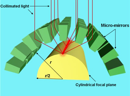
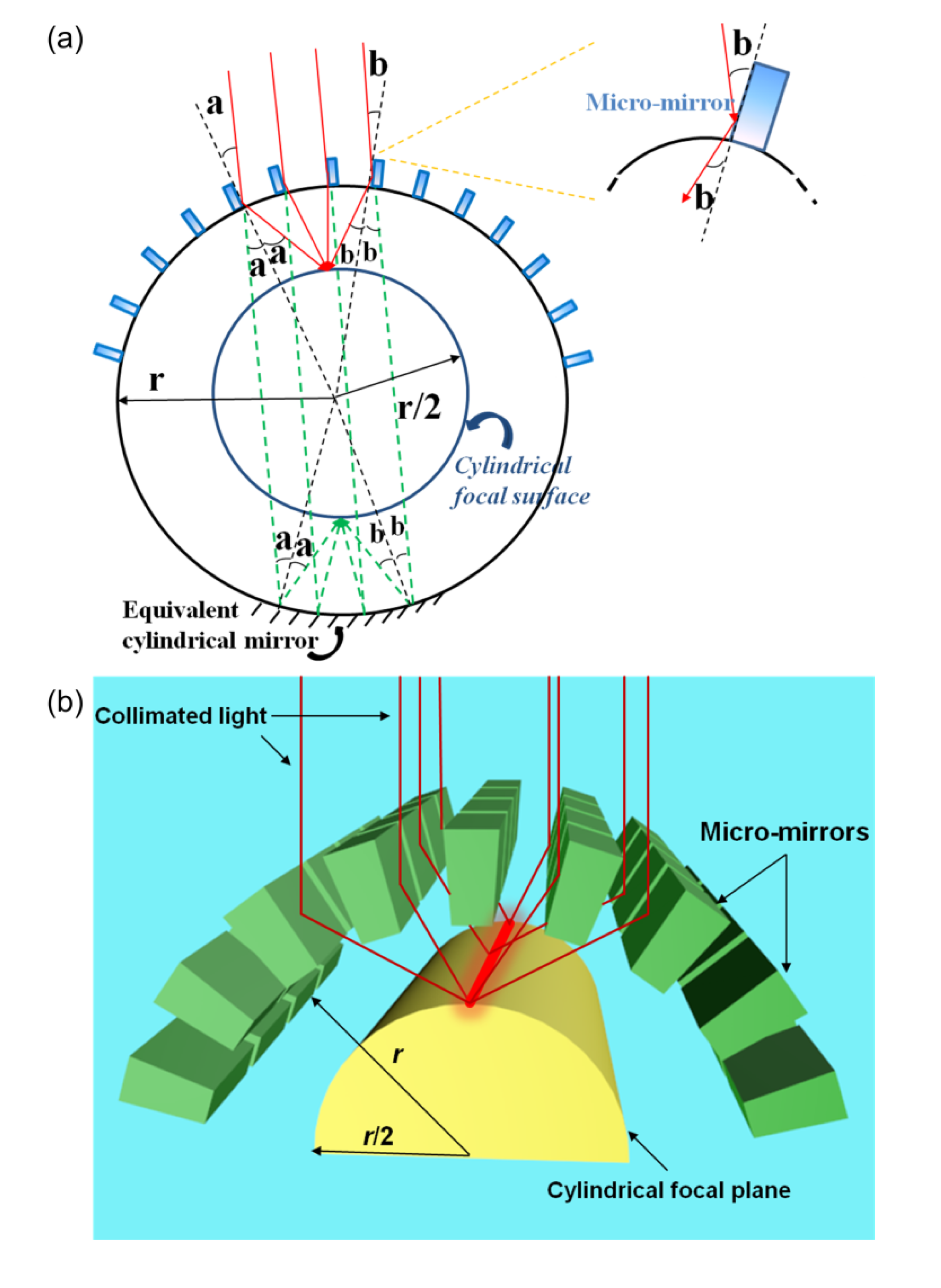
Figure 1a schematically illustrates the operating principle of our bio-inspired cylindrical lens. Here, a collimated beam is applied as the light source and only a part of the device is displayed to elucidate the focusing mechanism. From the cross-section view, high-aspect-ratio micro-mirrors with reflecting sidewalls are spherically arranged onto a thin, transparent, cylindrical elastomeric membrane (radius of curvature:
r) to focus the incident light by reflection. The orientation of each micro-mirror aims directly at the geometric center of the cylinder, as shown in the upper half of the cylinder in
Figure 1a. The incident rays are reflected by the sidewall of each micro-mirror and then converged in an overlapping fashion onto a cylindrical focal plane with the radius of curvature of
r/2 (
Figure 1a), thus, enhancing the light sensitivity of the device [
17]. Due to the spherical symmetry across the longitudinal axis of the cylinder, the focusing behavior of our device is almost equivalent to that by a cylindrical mirror with the same radius of curvature
r as shown in the bottom half of the cylinder in
Figure 1a. In this case, since the height of each micro-mirror (
i.e., 80 μm) is much smaller than
r (
i.e., 2.07 mm) of the cylindrical substrate, reflection is assumed to occur at the top surface of the cylinder. Therefore, the incident paraxial light is focused in the same way with a focal length
f of
r/2 (
i.e., 1.035 mm). The way our device focuses, thus, only differs from the cylindrical mirrors in that the object and the real image are located on the opposite sides of the device, much like a conventional refractive cylindrical lens, so that the imager does not obstruct the incoming light at all, as would happen in reflective cylindrical mirrors. Hence, a theoretical FOV up to 180° can ideally be achieved if a sufficiently large array of micro-mirrors covers the entire cylindrical substrate. An equivalent 3-D representation of
Figure 1a is shown in
Figure 1b to demonstrate the 1-D focusing and beam shaping mechanism of our device. The structure of our device consists of an array of distributed, 3-D, high aspect-ratio micro-mirrors with smoothened sidewalls curved into a cylindrical configuration. A beam of collimated rays is first reflected by the sidewalls and then focused into a straight line image along the longitudinal axis of the cylindrical focal plane with a radius of curvature of
r/2. In other words, the height of the image is expanded without altering its width. This schematic clearly shows the ability of such a device to elongate the focused image in only one axis (
i.e., 1-D), equivalent to that of the conventional refraction-based cylindrical lens.
Figure 1.
(a) Schematic representing the operating principle of our device with radius of curvature r under collimated illumination. The way the incoming light is reflected by an array of micro-mirrors is equivalent to that by a mirrored cylindrical surface with the same radius r (see both half of the circle). Due to the spherical symmetry, both have a same cylindrical focal plane with radius of curvature of r/2; (b) An equivalent, 3-D representation of (a) to demonstrate the 1-D focusing and beam shaping mechanism of our device.
3. Fabrication
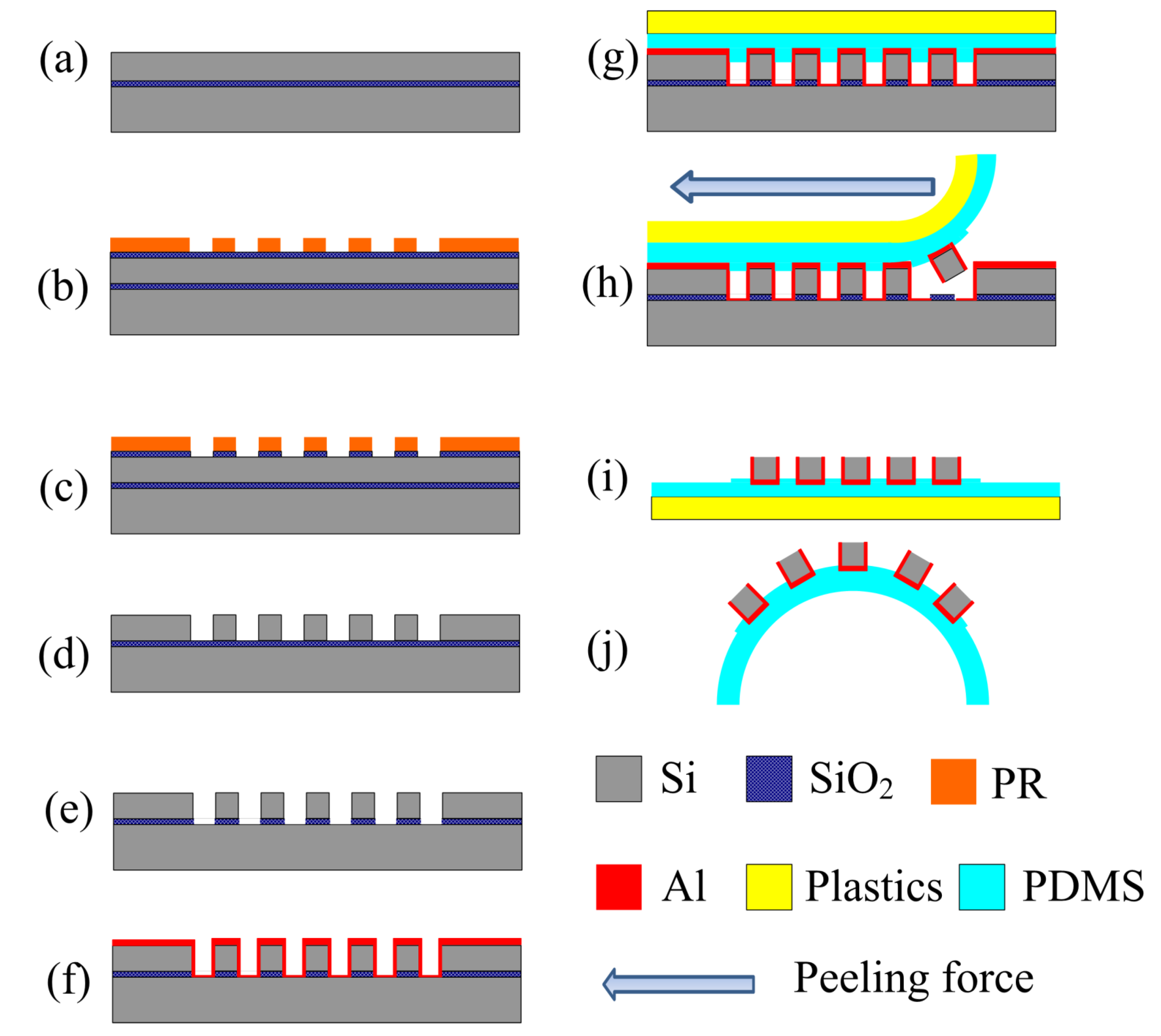
The detailed fabrication process flow for our bio-inspired cylindrical lens by a peeling micro-transfer printing method is illustrated in
Figure 2 [
18,
19]. The process began with a large-scale array of 3-D, high aspect-ratio silicon (Si) micro-mirrors with highly vertical and smoothened sidewalls on a p-type, (100) silicon-on-insulator (SOI) wafer (80 μm-thick device layer and a 2 μm-thick buried oxide (BOX) layer) via contact-mode lithography, reactive ion etching (RIE) and inductively coupled plasma-based (ICP) deep reactive ion etching (DRIE), as shown in
Figure 2a–d, respectively. The height, width, length and spacing of each micro-mirror were 80 μm, 40 μm, 120 μm, and 60 μm, respectively. Prior to the actual transfer-printing step (
Figure 2g), a couple of process optimizations had to be performed to guarantee that (1) sidewalls of each micro-mirror were smoothened to serve as perfect reflectors to focus light without undesirable aberrations and distortions in the images due to scattering; and (2) large-area surface coverage of the micro-mirror array on the cylindrical polymeric membrane to maximize the FOV of the device. First, the sidewall scalloping induced by the DRIE process was removed by a 45% potassium hydroxide (KOH, Fisher Scientific, Waltham, MA, USA) wet-etching process at 40 °C for 5 min [
20]. Second, the BOX layer was selectively undercut by a 6:1 buffered oxide etch (BOE, Fisher Scientific) to a level that all micro-mirrors were just slightly adhered to the underlying substrate and were ready to be transferred onto the elastomeric membrane. These two steps were represented in
Figure 2e. A layer of 400-nm aluminum with reflectivity over 90% in the visible spectrum was subsequently sputtered onto the smoothened facets of the Si micro-mirrors, as shown in
Figure 2f. Next, the preparation of a thin, transparent elastomeric membrane was made via a spin-coating process (spin rates 4000 rpm for 30 s) on a flat plastic substrate. The elastomeric membrane (refractive index
n = 1.43 and thickness
t = 400 μm) was made of pre-polymers of polydimethylsiloxane (PDMS, Sylgard 184, Dow Corning, Midland, MI, USA) with a mass ratio of 10:1 between the base and curing agent and later cured at 75 °C in a baking oven for 6 h. The width of the PDMS membrane was measured to be 6.5 mm. Once curved into a cylindrical configuration, the radius of curvature
r of our device was equivalent to 2.07 mm accordingly. The optical and mechanical properties of PDMS include high transparency at the visible wavelengths and excellent flexibility, making them ideal candidates for substrate materials of our cylindrical lens. Next, the SOI wafer was brought into a conformal contact with the PDMS membrane (
Figure 2g). In fact, prior to the actual contact, a thin, partially cured PDMS of the same mixing ratio was coated onto the PDMS membrane to serve as a glue layer to enhance the adhesion between the membrane and the micro-mirror array. The Si micro-mirrors were successfully transfer-printed to the flat PDMS membrane by a peeling force exerted in the lateral direction, as shown in
Figure 2h,i.
Figure 2j concluded the fabrication process as an array of micro-mirrors built on a flexible PDMS membrane was curved into a cylindrical configuration. The radius of curvature
r was measured to be 2.07 mm, making the theoretical focal length of our device to be 1.035 mm.
Figure 2.
Schematic illustrating the detailed fabrication process of the peeling micro-transfer-printing method applied to realize our device. (a) A large-area array of micro-mirrors fabricated on an SOI wafer by the following steps: (b) Contact-mode standard lithography; (c) Etching of oxide hard mask by RIE; (d) DRIE process; (e) Si sidewall smoothening by a 45% KOH wet-etching process. Plus, a selective undercut etching of the BOX layer by BOE solution; (f) Al sputtered onto the Si pillars to create an array of micro-mirrors; (g) A transparent, flexible PDMS membrane pressed against the structured SOI wafer to achieve conformal contact; (h) A peeling stress in the lateral direction lifting the micro-mirror array onto the PDMS membrane; (i) Micro-mirror array successfully transferred onto the PDMS membrane; (j) The fabrication concluded with the production of an array of micro-mirrors on a cylindrical PDMS membrane. The dimensions in this figure are not to scale.
4. Results and Discussion
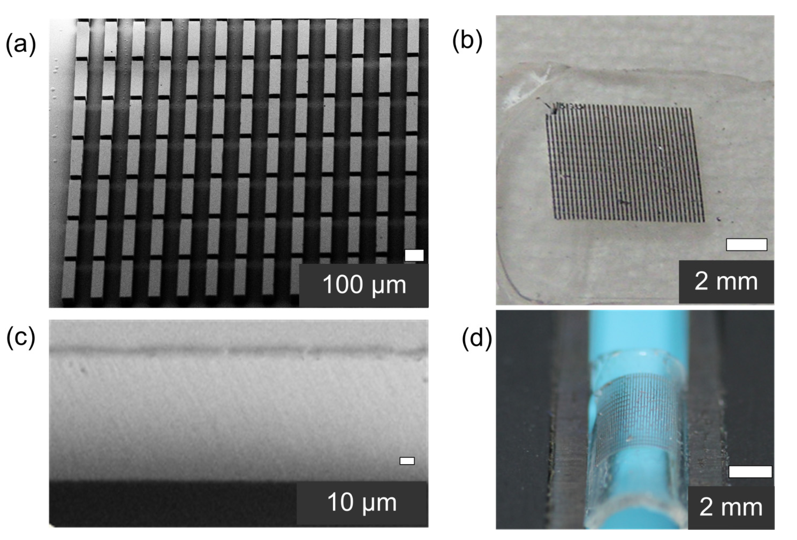
Figure 3 shows scanning electron microscopy (SEM) images representing part of a 55-by-50 array of 3-D, high aspect-ratio Si micro-mirrors (a) fabricated on the SOI wafer and (b) transferred onto a thin, transparent and flexible PDMS membrane.
Figure 3c highlights the highly vertical and smoothened facets of the micro-mirror covered with aluminum, which are critical to an optical reflector.
Figure 3d presents the picture of the micro-mirror array curved into a cylindrical configuration by a cylindrical lens holder. Again, the radius of curvature
r and the theoretical focal length were measured to be 2.07 mm and 1.035 mm, respectively. The yields of the fabrication process were high as more than 90% of the micro-mirrors have been reproducibly transferred from the SOI wafer to the PDMS substrate.
Figure 3.
Representative images of the detailed microstructures of a bio-inspired cylindrical lens. SEM images of a portion of a 55-by-50 array of 3-D, high aspect-ratio Si micro-mirrors (a) fabricated on the SOI wafer and (b) transferred onto a flat PDMS membrane; (c) SEM image highlighting the uniformly aluminum-covered, smoothened facets of the micro-mirror where the reflection takes place; (d) close-up picture of the micro-mirror array on the PDMS membrane curved into a cylindrical configuration by a lens holder.
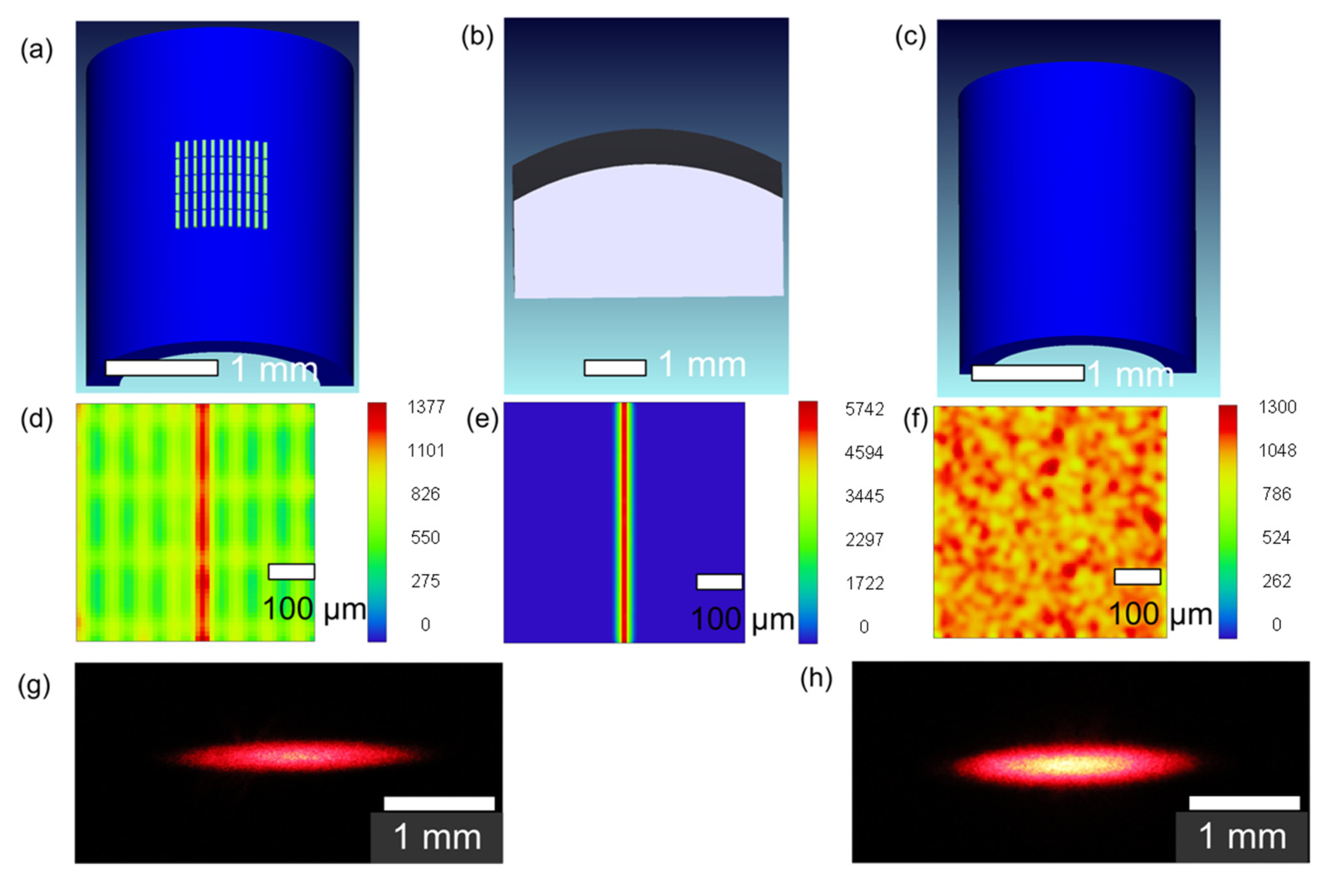
The primary functions of a conventional cylindrical lens are focusing and beam-shaping because it expands light in only one axis. Here, an extensive theoretical study was performed to compare the focusing behavior between our device, a conventional refractive cylindrical lens and a thin cylindrical PDMS membrane utilizing the optical simulation tool Zemax.
Figure 4d–f shows simulated intensity profiles of various corresponding devices of our micro-mirror array on a cylindrical PDMS substrate (
Figure 4a), a conventional refractive cylindrical lens (
Figure 4b) and a cylindrical PDMS membrane itself, with a collimated, rectangular incoming light source (
Figure 4c). For simplicity, an 11-by-5 array of reflective Si micro-mirrors radially arranged on a transparent, cylindrical PDMS membrane (refractive index
n = 1.43, thickness
t = 400 μm and radius of curvature
r = 1.3 mm) was modeled to represent our device, as shown in
Figure 4a. A Gaussian beam profile was applied to represent a collimated laser beam. Well-focused line images shown in
Figure 4d,e can be obtained by both
Figure 4a and
Figure 4b but not by
Figure 4c, indicating that our device has a 1-D focusing and beam-shaping capability equivalent to that of a conventional cylindrical lens, consistent with the operating principles shown in
Figure 1b. One thing should be noted that the focal length of our device calculated in the Zemax was almost 0.65 mm, agreeing to theory.
To characterize the optical performances of our device in terms of focusing and beam-shaping, real focused images generated by our device (
Figure 4g) and a commercial cylindrical lens (
Figure 4h) were captured and compared to those simulated by theoretical modeling shown in
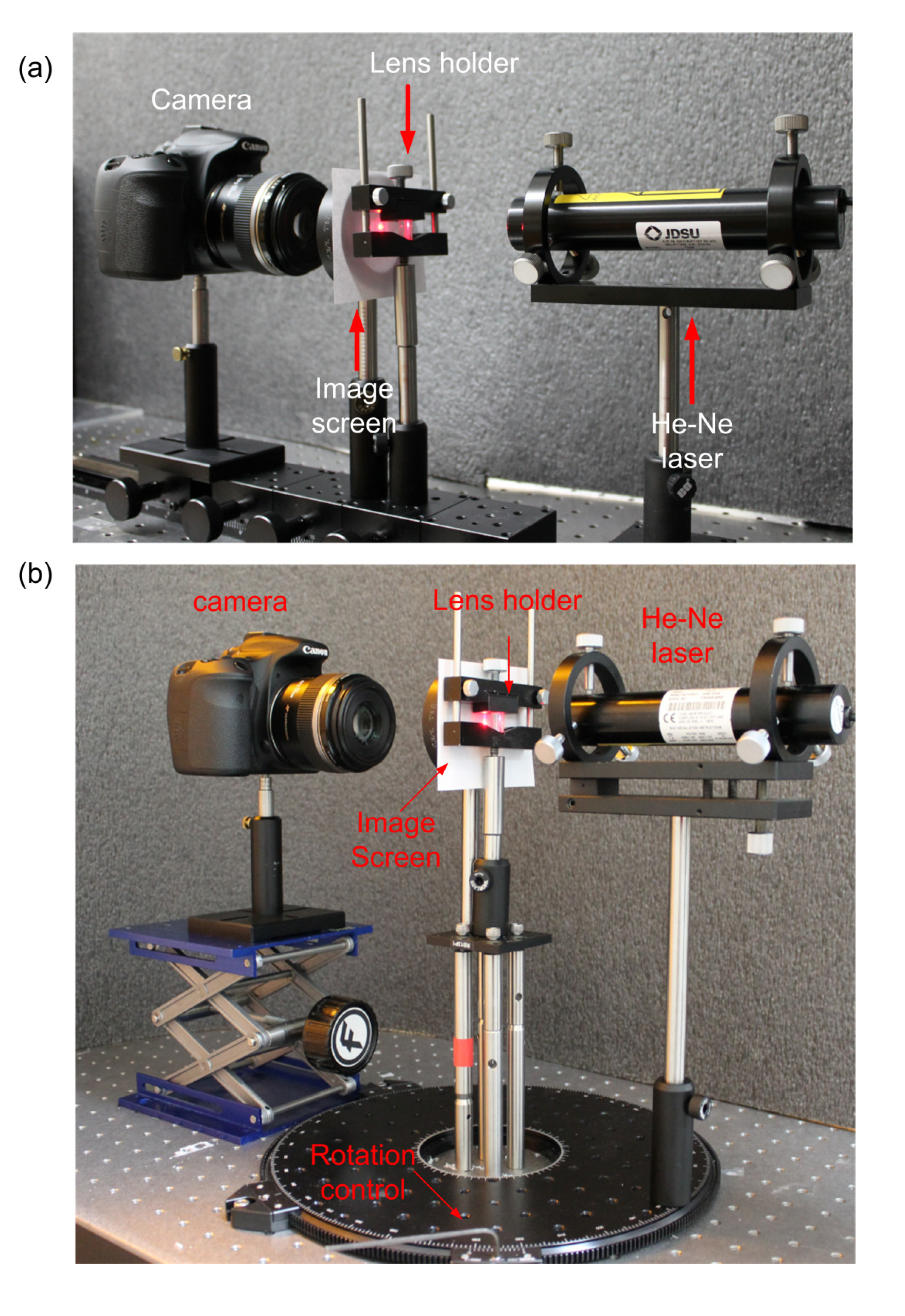
Figure 4a,b. Both focused images were obtained without any post-image processing. A He–Ne laser (wavelength = 630 nm, JDS Uniphase 1107, Milpitas, CA, USA) was applied to produce a collimated light source. The device under test was placed at the lens holder (Edmund Optics, Barrington, NJ, USA). The holder pinched our device by the edges of the PDMS membrane to curve it into a cylindrical shape with radius of curvature close to 2 mm. The out put focused images were first projected on a planar paper screen and then captured by a single lens reflex camera (Canon, EOS 60D, Tokyo, Japan) from behind. The entire optical characterization system was built on an optical linear translation stages and track (Edmund Optics) to ensure excellent alignment, stability and precise focal length measurement see
Figure 5a for the system set-up. For our device, the focal length was measured to be approximately 1 mm in
Figure 4g, equivalent to the
r/2. Again, the focusing characteristics of our device were consistent with theory. More importantly, the overall beam-shaping performance in terms of the quality and clarity of the focused line image generated by our device (
Figure 4g) was qualitatively comparable to those acquired by a commercial cylindrical lens with comparable size (
H = 10.0 mm,
L = 12.0 mm,
f = 10.0mm, N-BK7 plano-convex lens, Thorlabs, Newton, NJ, USA) in
Figure 4h. One thing should be noted: the periodic oscillation observed in the simulated image in
Figure 4a stems from (a) the artifact of the periodic structures of the micro-mirror array within our device and (b) part of the incident light rays are directly passing through our device without reflecting upon the sidewalls. Both results in a somewhat blurry background expose around the focal line. This happens mostly in such area so that the effect is further enhanced. It is difficult to observe in the experimental image in
Figure 4g due to its small size and more importantly, its dimmer intensity compared to the focused image. In addition, the exposure setting of the camera was kept low and hence made it even harder to be seen due to the limited dynamic range of the camera.
Figure 4.
Zemax simulated intensity profiles (d)–(f) of various corresponding devices of (a) our micro-mirror array on a cylindrical PDMS substrate; (b) a conventional cylindrical lens; and (c) a cylindrical PDMS membrane itself, with a collimated light source. The device structures in (a)–(c) are schematically drawn. Pictures of focused line images produced by (g) our device and (h) a commercial refractive cylindrical lens. Note that the beam-shaping performances of both focused line images are almost comparable. The wavelength of the laser beam was 633 nm.
The focusing performance of our device primarily depends on two factors: dimensions of the micro-mirrors and the aspect ratio of each mirror. The former directly dictates the degree of diffraction, i.e., the smaller the inter-mirror spacing, the worse diffraction can be observed. Since the smallest dimensions within our device are still much larger than the wavelength, the effect of diffraction is considered little. The aspect ratio of each mirror determines the number of reflections of the incident light rays while passing through our device. The focusing behavior is contributed by one-time reflection on the sidewalls of the micro-mirror, while two-time reflection can cause the light rays deviate from the focal point. As the aspect ratio of each micro-mirror increases, the number of two-time reflections increases accordingly and broadens the spatial light distribution. As a result, the focusing performance is degraded. In our study, the aspect ratio of 2:1, similar to that found in natural RSCEs (i.e., 2:3), can allow the majority of the incident rays to focus via one-time reflections and thus serves as the basis to determine the aspect ratio and dimensions of our device.
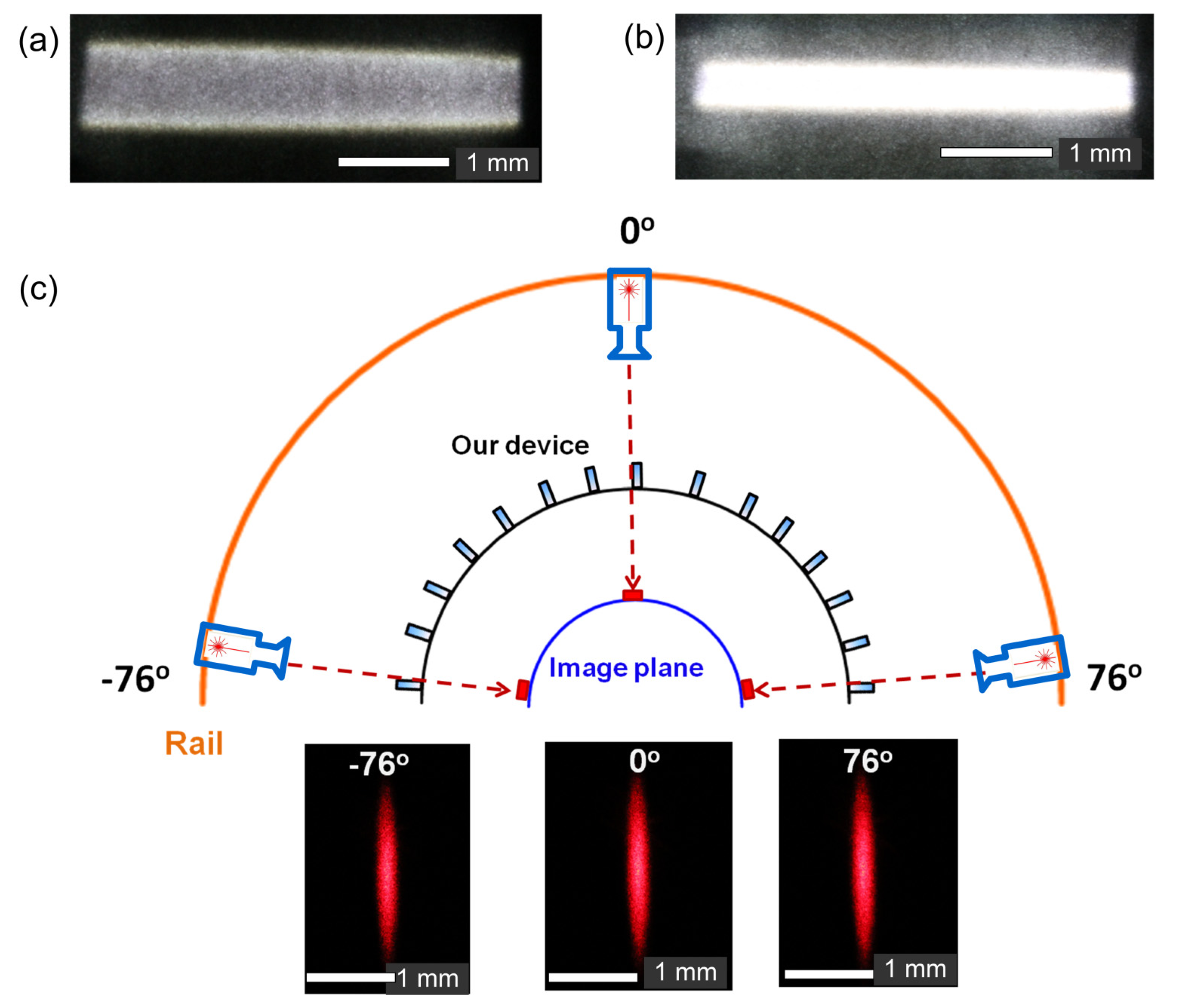
The ability of our device to achieve minimum chromatic aberrations in the focused line images is best demonstrated and compared in
Figure 6a,b. A rectangular, non-collimated white light was applied as the source. Focused line image produced by the same commercial refractive plano-convex cylindrical lens in
Figure 6a showed strong chromatic aberration (
i.e., fringes of purple and yellow at the center and along the boundaries of the image, respectively), while that generated by our device in
Figure 6b revealed no signs of chromatic aberration. Identical camera exposure settings were applied to capture both images. The dimmer aura surrounding the focused line image in
Figure 6b resulted from the fact that few of the incident rays were reflected twice by the micro-mirror array before exiting our device. The reason that this aura was revealed in
Figure 6b was due to larger exposure setting of the camera than those used in
Figure 4g. The superior advantage of minimum chromatic aberration found in our device enables it to perform dispersion-free imaging operations over a wide visible light spectrum.
Spherical aberration, coma and astigmatism are commonly used to quantitatively characterize the extent of deviation from the normal performance in a given optical system. For our cylindrical lens, these parameters were measured with a Shack-Hartmann wavefront sensor (Thorlabs, WFS series) [
21,
22,
23,
24]. Based on the results, our device showed modest aberrations since the measured aberrations (
i.e., coma, tilt, spherical aberration, astigmatism) were modest and comparable to those measured from the same commercial refractive lens described above, as shown in
Table 1. All parameters displayed here are in the unit of waves.
Table 1.
Zernike coefficients of our device and a commercial refractive cylindrical lens (N-BK7) characterized by Shack-Hartmann wavefront sensor system.
Table 1.
Zernike coefficients of our device and a commercial refractive cylindrical lens (N-BK7) characterized by Shack-Hartmann wavefront sensor system.
| Zernike Polynomial | Our device | N-BK7 lens | Physical meaning |
|---|
| 2ρcos(θ) | 0.095 | 0.039 | Tilt in
x-axis |
| 2ρsin(θ) | 0.272 | 0.442 | Tilt in
y-axis |
| ρ2cos(2θ) | 3.259 | 3.933 | Primary Astigmatism |
| (3ρ2 − 2ρ)cosθ | −0.135 | −0.028 | Coma in
x-axis |
| (3ρ2 − 2ρ)sinθ | −0.035 | −0.057 | Coma in
y-axis |
| 6ρ4 − 6ρ2 + 1 | −0.07 | −0.095 | Spherical aberration |
Another fascinating feature of our device lies in its ability to achieve a wide angle (FOV) of 152° enabled by the spherical geometry across the longitudinal axis [
25,
26], as demonstrated in
Figure 6c The FOV measurement started with the sequential illumination of our device placed on a fixed stage at the center of the circular rotating breadboard (RBB12, Thorlabs) by a He-Ne laser mounted on the circumference (see
Figure 5b for the system set-up). Three focused line images captured from three different angles, −76° (left), 0° (center), and 76° (right), in one dynamic scan were selected to represent the total 152° viewing angle. Identical camera exposure settings were used to capture all three representative figures. The result clearly demonstrates the system’s ability to achieve wide-angle FOV. Owing to fact that our cylindrical lens possessed spherical symmetry in any cross section perpendicular to the longitudinal axis of the device and hence no primary optical axis was specified, all representative focused images showed comparable clarity without noticeable distortion and blur commonly seen in most wide-angle fish-eye lenses. The image quality of the focused line images in terms of clarity and brightness remained identical over the entire scanning path corresponding to the 152° FOV.
Figure 5.
Photograph of the optical setup used for (a) image acquisition and (b) FOV measurement.
Figure 5.
Photograph of the optical setup used for (a) image acquisition and (b) FOV measurement.
Figure 6.
Focused line images produced by (a) a commercial plano-convex refractive cylindrical lens revealing strong chromatic aberration and (b) our device without chromatic aberration. These two images demonstrated clear evidence highlighting the distinctive differences in focused images with and without chromatic aberration due to different focusing mechanisms: refraction vs. reflection; (c) composite schematic and pictures representing 152° of FOV achieved by our device captured at three representative angles of incidence: −76° (left), 0° (center) and 76° (right).


