1. Introduction
Today, in this rapidly-developing world of micro-communications, how to develop micromechanical oscillators and filters with high linearity, high power handling capability and low motional resistance, is a matter of debate. Silicon micromechanical resonators, due to their small size, low cost and compatibility with integrated circuit (IC) technology, are a promising alternative to surface acoustic wave (SAW) and quartz crystal resonators in wireless transceivers [
1,
2]. However, low motional resistance, high signal-to-noise ratio and high power handling make it difficult to handle the linearity and small size, and may exclude the use of these resonators in some communication applications. According to Leeson’s equation, which models the phase noise-to-carrier ratio in a resonator-based oscillator, the near carrier noise can be reduced by increasing both power handling capability and quality factor. Therefore, micromechanical resonators, due to their small size, should be driven at a high excitation value, which causes them to turn easily into nonlinear regimes [
3,
4]. However, dynamic pull-in instability limits the structure stable displacement range. In dynamic pull-in instability, the electrostatic force increases much higher than the spring restoring force, and the micromechanical resonator sticks to one of the stationary electrodes. However, the predicted maximum amplitude of vibration due to other effects, such as coupling, between in-plane and out-of-plane modes, frequency hysteresis and intermodulation distortion (IMD) that distort the frequency response, is not reached [
5,
6]. The ability to accurately model nonlinearity and investigate its effect on frequency stability and intermodulation distortion is, therefore, a key requirement to optimum design of silicon micromechanical resonators. There are several mechanical and electrical nonlinearities in silicon micromechanical resonators. Depending on the resonator design and operating conditions, different nonlinearities may be dominant and result in hardening or softening behavior of the dynamic behavior of micromechanical resonators [
7]. Many research works have been conducted on modeling nonlinear effects in micromechanical resonators. Zhang
et al. [
8] investigated the dynamic responses and nonlinear dynamics of the beam-based resonant sensor, using a mass-spring-damping dynamic model. They showed the dependency of the dynamic response on the squeeze film damping and operating conditions. Mestrom
et al. [
7] studied the frequency responses and the nonlinear dynamic properties of clamped-clamped (C-C) beam resonators and predicted the hardening behavior. They also compared their analytical results with experimental results and found a reasonable agreement. Wang
et al. [
9] experimentally extracted the nonlinear mechanical stiffness of the breathe-mode ring resonator. They presented the softening behavior of these resonators and demonstrated that material nonlinearity limits maximum power handling.
However, the study of the nonlinear behavior of distortion in micromechanical resonators is inadequate, and previous works have only focused on the nonlinear dynamic behavior and frequency stability. Navid
et al. [
10] and Lin
et al. [
11] derived analytical formulations for IMD using the third-order input intercept point (IIP
3). They measured IIP
3 at the offset of Δ
ω = 2π × (200 kHz) for a clamped-clamped beam resonator and contour-mode disk resonator, respectively. They found that the electrostatic force is the primary source of IMD and there is a tradeoff between linearity and motional resistance. Unlike previous works, Alastalo
et al. [
6,
12] studied the third-order intermodulation (IM
3) in electrostatic micromechanical resonators, including mechanical nonlinearities. However, assuming micromechanical resonators with a high quality factor and ignoring some second-order nonlinearity components, they used a first-order approximation to estimate the displacement and motional current due to interference.
This paper deals with the nonlinear behavior of distortion in silicon bulk-mode ring resonators. First, a comprehensive nonlinear model, including the effect of large amplitudes around the primary resonance frequency, material and electrical nonlinearities, is derived. The effects of the quality factor and operating conditions on the resonant pull-in instability are then addressed. Next, the second-order approximation for motional current due to IMD is calculated using perturbation techniques and harmonic balance method. Finally, the effect of operating conditions including the ac-drive and DC-bias voltages and quality factor on the harmonic and third-order intermodulation distortions are investigated.
2. Basic Assumptions
Bulk-mode ring resonators, due to their high structural stiffness, ring geometry and having four quasi-nodal points at their outer periphery in some in-plane bulk-modes, offer lower motional resistance and higher quality factors. Hence, these resonators are more extensively developed in radio frequency (RF) transceiver front-end architectures [
13,
14]. In order to derive the in-plane vibrations and resonant frequencies, it is assumed the ring resonator thickness is much smaller than the ring width (
tr <<
Ro −
Ri), and the support beam widths are much smaller than the outer ring radius. Therefore, the ring resonator is modeled as an annular thin-plate with free edge, and the vibration variables are independent of the resonator thickness and its support beams. Moreover, it is assumed that the ring resonator is made of single crystal silicon. Therefore, the equation governing the in-plane vibration of an annular ring, ignoring body force and internal heat source, can be given by [
15,
16]:
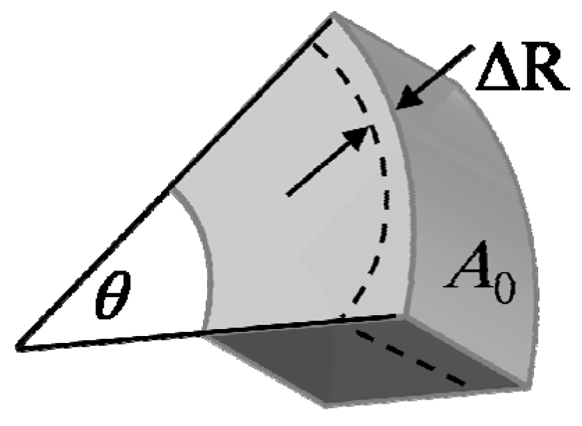
where E, υ and ρ are respectively Young’s modulus, Poisson ratio and density of structural material of the resonator. The parameters A and A0 denote the transduction area under large and small structural deformations, respectively. The displacement vector u = xer + weθ is defined in terms of the radial (x) and circumferential (w) displacements in polar coordinates through the time and mode shape functions as follows:
where
where at the natural resonance frequency of ωnm = hnm√(E/ρ(1 − υ2)), the radial displacements at the inner and outer radii can be assumed as:
where Uo = Ur│r = Ro and Ui = Ur│r = Ri can be expressed by following equation:
In the above equations,
Jn and
Yn are Bessel functions of first and second kinds, respectively.
hnm and
knm are mode consonants of the bulk-mode of (
n,
m), where
n corresponds to the circumferential order and
m corresponds to the radial harmonic [
16]. The relationship between
knm and
hnm is given by:
knm/
hnm = √2/(1 −
υ), and the elastic wave constants of (
Bn/
An,
Cn/
An,
Bn/
An) can be found by solving the following equation:
where the elements of
M are given by [
13,
16]:
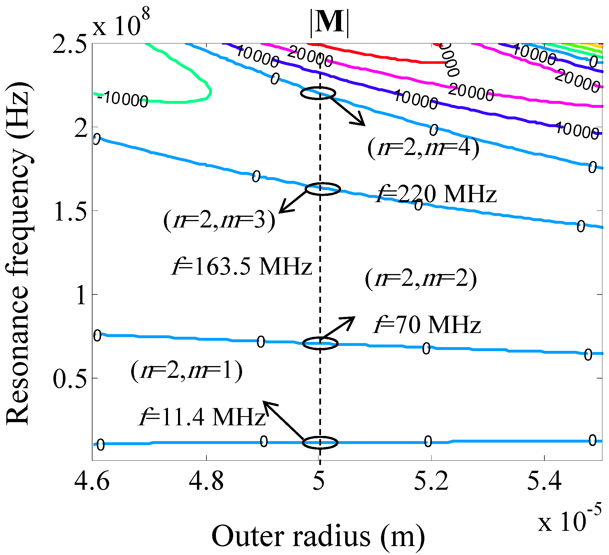
The resonance frequencies of the ring resonator with a given geometry can be obtained by the numerical solution of |
M| = 0, as shown in
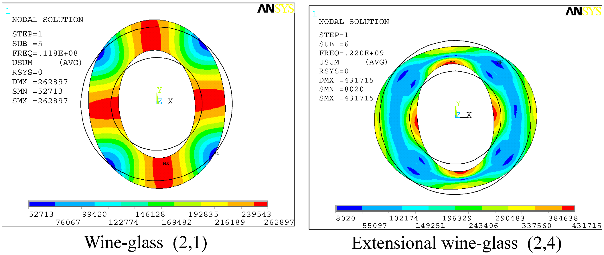
Figure 1. Moreover, the analytical results and mode shapes can be verified and simulated using finite element method (FEM) software, such as ANSYS, as shown in
Figure 2.
Figure 1.
Numerical calculation of mechanical resonance frequency for second-order modes (2, m) in silicon ring resonator with Ri = 30.16 µm and t = 2 µm.
Figure 1.
Numerical calculation of mechanical resonance frequency for second-order modes (2, m) in silicon ring resonator with Ri = 30.16 µm and t = 2 µm.
Figure 2.
ANSYS simulation of the resonance frequencies for in-plane bulk-modes of silicon ring resonator with Ri = 30.16 µm, Ro = 50 µm and t = 2 µm.
Figure 2.
ANSYS simulation of the resonance frequencies for in-plane bulk-modes of silicon ring resonator with Ri = 30.16 µm, Ro = 50 µm and t = 2 µm.
The rest of the paper focuses on the mode shapes of (2,
m), like wine-glass (2,1) or extensional wine-glass (2,4). Thus, the subscript
n = 2 representing the second-order modes will be used and the subscript
nm is also omitted in the following equations. Moreover, the extensional wine-glass (EWG) mode ring resonator with the specifications presented in
Table 1 has been used to evaluate the frequency response caused by nonlinear effects.
Table 1.
The related parameters for silicon ring resonator.
Table 1.
The related parameters for silicon ring resonator.
| Parameter | Value | Unit |
|---|
| Linear Young’s modulus (E0) | 170 | GPa |
| Poisson ratio (υ) | 0.28 | |
| Density (ρ) | 2,330 | kg/m3 |
| First order corrections (E1) | −2.6 | |
| Second order corrections (E2) | −8.1 | |
| Inner radius (Ri) | 30.16 | µm |
| Outer radius (Ro) | 50 | µm |
| Thickness (tr) | 2 | µm |
| Electrode angle (θe) | 70 | deg |
| Resonance frequency (fnm) | 220 | MHz |
3. Nonlinear Distributed Modeling Approach
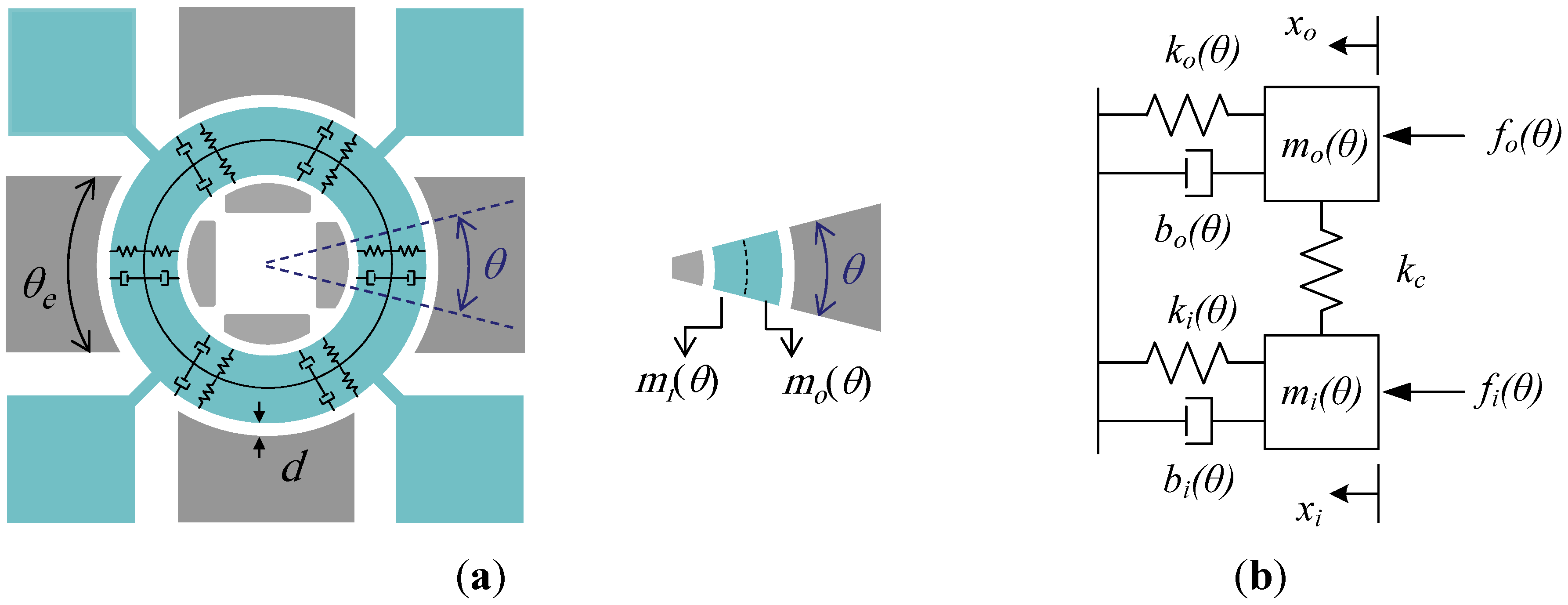
The correct modeling of micromechanical resonators is an important step to analytical investigation and optimum design. Since both actuation and detection are realized using the inner and outer electrodes, the ring resonator can be assumed as two separate ring resonators coupled together at the middle distance between the inner and outer edges. Therefore, each ring resonator can be modeled as a distributed element, as shown in
Figure 3(b).
Figure 3.
(a) The schematic view of the ring resonator; (b) The equivalent mass-spring-damper system of an infinitesimal element of the ring resonator.
Figure 3.
(a) The schematic view of the ring resonator; (b) The equivalent mass-spring-damper system of an infinitesimal element of the ring resonator.
Considering an infinitesimal element, the gap spacing variations in capacitive transducers are assumed along the radial direction. Thus, the governing equation of a second-order mechanical system (mass-sprin-damper) for an infinitesimal element can be expressed as:
where m denotes the lumped mass and b, km and kc are damping coefficient, mechanical stiffness and coupling stiffness, respectively. The parameters fs and fd are the radial electrostatic force per unit radian from the sense and drive electrodes, respectively. The subscripts i and o denote the inner and outer ring resonators, respectively. The effective masses for the infinitesimal elements in the inner and outer ring resonators are given by:
Assuming the first mode as the dominant mode of the system, the inner to outer displacement ratio can be expressed as |xi(t,θ)/xo(t,θ)| ≈ |(Ui/Uo)| = γ. Therefore, substituting Equations (6) and (7) into Equations (11) and (12), and combining them together results in the following expression:
4. Modeling the Origins of the Nonlinearities
Nonlinearities in micromechanical resonators generally arise from electrical and mechanical origins. Electrical nonlinearities include the electrostatic force nonlinearity caused by the variable gap capacitive transducers and fringing effects. The fringing effects due to both the finite resonator thickness and the electrodes are considerable. The general trend of fringing fields is to increase the effective capacitance of the capacitive transducers. Therefore, the electrostatic force is modeled using the parallel plate capacitance approximation, along with the correction term of Cf representing fringing effects as follows:
where
where
VP is the DC-bias voltage and
C0o =
εRotr/
d and
C0i =
εRitr/
d imply the capacitance over the outer and inner initial gaps, and
d is the corresponding initial gap spacing. According to the sense electrodes configuration, the value of
β would be equal to 1 or −1 if the electrodes are placed at the same side or opposite side, respectively. The correction term of capacitance for the fringing effects depends on the dimensions of the structure as follows [
17]:
where λ = d/tr is the initial gap-to-thickness ratio.
A large structural deformation can be contributed to geometric and material nonlinearities; classified as the mechanical nonlinearities. Mechanical nonlinearities are created by the stresses that develop inside the resonator structure under large displacements. Depending on the operation mode, material or geometric nonlinearities can be dominant in micromechanical resonators. Unlike electrical nonlinearities, which can be easily represented by Taylor series with respect to displacement, mechanical nonlinearities can be approximated by deformation analysis for the bulk-mode ring resonator. Therefore, the mechanical nonlinearity is first modeled by considering the higher order terms to the mechanical stiffness as follows:
where
As shown in
Figure 4, the geometric nonlinearities caused by large radial displacements in infinitesimal element could be addressed as follows:
where
Figure 4.
The geometric variation in an infinitesimal element of the ring resonator.
Figure 4.
The geometric variation in an infinitesimal element of the ring resonator.
Moreover, the large displacement develops internal stresses inside the structure of the resonator, and therefore, nonlinear elastic behavior of silicon results in a nonlinear Young’s modulus [
18]:
where
E1 and
E2 denote the first-order and second-order corrections to linear Young’s modulus of
E0, respectively. The values of
E1 and
E2 are listed in
Table 1 for bulk-mode silicon oriented along <100> [
4]. Substituting Equations (23) and (25) into Equation (1), multiplying by cos(2
θ), and then integrating both sides, from
θ = 0 to
θ = 2π results in the approximate expressions for third-order mechanical stiffness coefficients,
k2o and
k2i, as follows:
where
The second-order nonlinearity term (k1i,o) caused by symmetrical structure of the ring structure and mode shape is omitted. Using the self-written numerical codes in MATLAB, the values of k2o and k2i for the case study of this paper were respectively calculated to be −3.79 × 10¹¹ N/m and −1.3662 × 10¹⁰ N/m,.
5. Analysis of Distortion
According to nonlinearity in the bulk-mode ring resonator and multiplying Equation (16) by cos(2θ), and then integrating over the range of 0 to 2π, the governing equation of a second-order mechanical system is rewritten as:
where
ωt is the resonance frequency caused by electrical nonlinearity, and
Q denotes the quality factor. The notations used in Equation (30) are presented in
Table 2, where
θe denotes the electrode-to-resonator overlap angle.
Table 2.
Definitions used in Equation (30).
The DC component in Equation (30) has no effect on the nonlinear analysis and it can be ignored as follows:
where
The approximate analytical method can be used to solve Equation (31). Assuming weak nonlinearities and the value of the product viVP, below the resonant pull-in condition, the problem can be solved using the perturbation technique. The method assumes the resonance frequency along with the solution vary as a function of perturbation terms as:
The second-order approximation of the solution is sufficient to get a more accurate evaluation of the displacement as follows:
Substituting Equations (35) and (36) into Equation (31) and grouping the terms in power of d, the two following expressions are obtained as:
When ac-drive voltage of vi (t) = |vi|cos(ωt) is applied, the solution of Xo0(t) would be:
where H΄ω and H˝ω denote the real and imaginary parts of the transfer function of H(ω), respectively.
Substituting Equation (39) into the right hand side of Equation (38) and setting the secular terms to zero, the expression of ω1 is approximately given by:
Thus, substituting Equation (41) into Equation (36), ώt, the resonance frequency caused by mechanical and electrical nonlinearities, is expressed as follows:
As shown in Equation (42), ώt is a function of the ac-drive amplitude. Substituting Equation (39) into Equation (38), the solution of Xo1(t) is calculated and, therefore, Xo(t) can be expressed as:
where
where H΄nω and H˝nω (n = 2,3) denote the real and imaginary parts of the transfer function of H(nω), respectively. Substituting Equation (43) into Equation (6), the motional current for the infinitesimal element of the micromechanical ring resonator can be obtained using the following equation:
Multiplying by cos(2θ) and then integrating both sides, from 0 to 2π, the total motional current due to the ac-drive voltage at the resonance frequency is finally derived as:
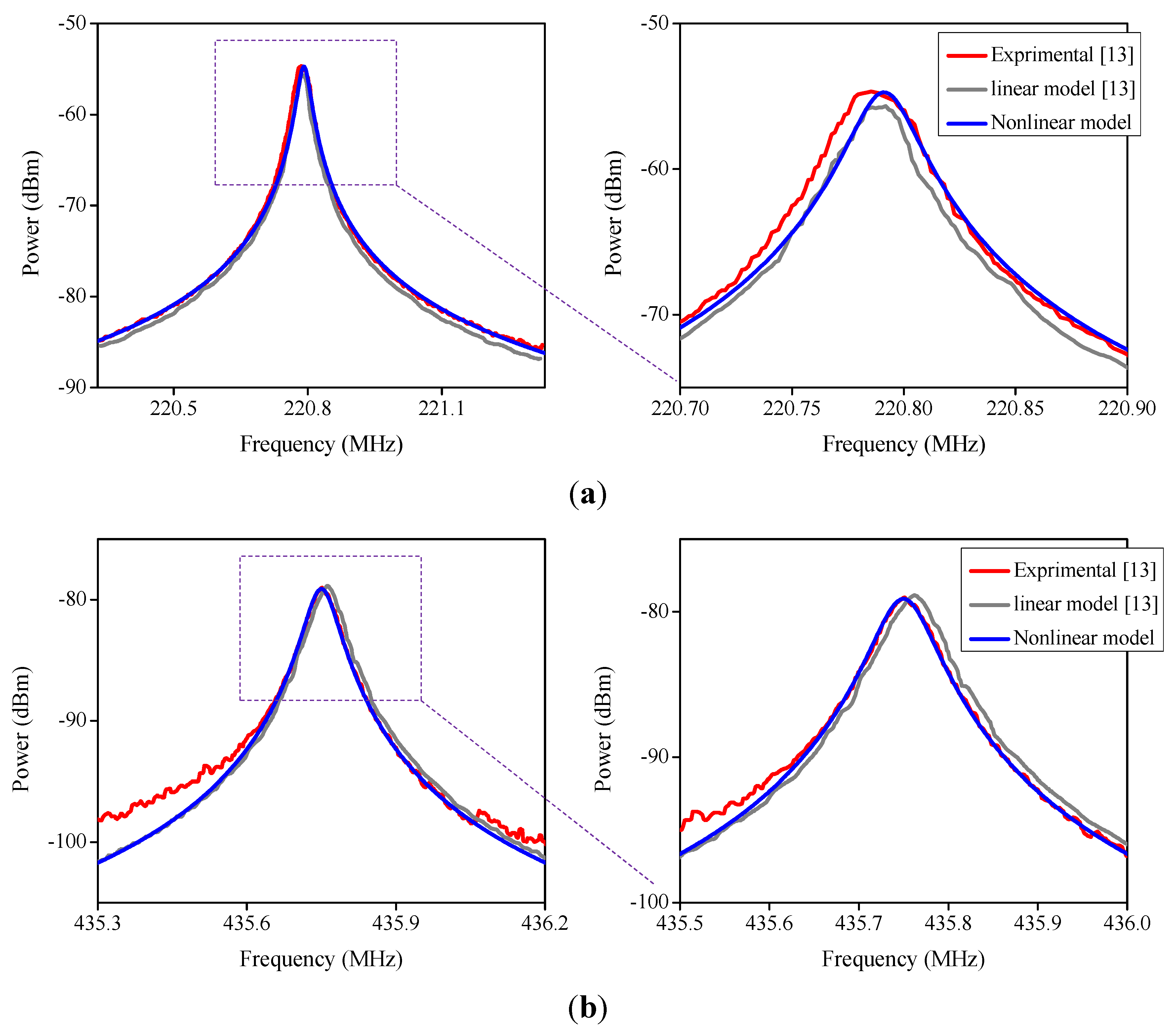
The experimental results of the study conducted by Xie
et al. [
13] were used to experimentally verify a derived expression for the proposed model in a linear regime. The frequency response was measured experimentally using the mixing approach. Therefore, the equations of |
vi| = (|
vLO||
vRF|)/(2
VP),
Ke = [
VP2 + 1/2(|
vLO|
2)]
d−2(
γC0i +
C0o)(sin(2
θe) + 2
θe), and
Po = (
RL|
io|
2)/2 (corresponding to a
RL = 50 Ω), are used in the derived expressions, to match the mixing approach with the proposed model [
19]. Moreover, in order for the analytical and the experimental results to be matched, the ring resonator dimensions, such as inner and outer radius, were adjusted as shown in
Table 3.
Table 3.
Designed parameters of polysilicon ring resonators.
Table 3.
Designed parameters of polysilicon ring resonators.
| Resonance Frequency (MHz) | Inner Radius (µm) | Outer Radius (µm) |
|---|
| Design Values [13] | Adjusted Values [13] | Adjusted Values [This Work] | Design Values [13] | Adjusted Values [13] | Adjusted Values (This Work) |
|---|
| 220.8 | 30.5 | (30.5 + 0.47) | (30.5 + 0.38) | 50 | (50 − 0.47) | (50 − 0.16) |
| 435.8 | 32.6 | (32.6 + 0.12) | (32.6 − 0.05) | 42.3 | (42.3 − 0.12) | (42.3 + 0.1) |
However,
Figure 5 shows that the frequency responses of the nonlinear model have good agreement with the experimental results with smaller adjustments than used in the linear analytical model.
Figure 5.
The frequency response for polysilicon extensional wine-glass (EWG) ring resonators with resonance frequency of (a) 220.8 MHz; (b) 435.8 MHz.
Figure 5.
The frequency response for polysilicon extensional wine-glass (EWG) ring resonators with resonance frequency of (a) 220.8 MHz; (b) 435.8 MHz.
5.1. Resonant Pull-In Condition
Accurate determination of the resonant pull-in condition is critical in the design process to determine the dynamic instability and power handling of the micromechanical resonator. Unlike the static pull-in voltage where analytical formulas and numerical approaches have been well established to estimate it accurately [
20,
21], dynamic pull-in voltage does not have a precise threshold and it depends on the quality factor and operating conditions [
22]. Nayfeh
et al. [
23] applied a shooting method on a reduced-order model of a micro-beam to study dynamic instability near primary and sub-harmonic resonances. They show that dynamic pull-in obtained by adding a resonant
ac actuation force to the static DC component helps pull-in happen at lower voltages. Fargas-Marques
et al. [
24] studied pull-in instability under resonant excitation, considering the nonlinear mechanical stiffness effect that appears with large amplitude oscillations. They used energy methods to derive analytical expressions for static and dynamic pull-in voltages. They also derived an analytical resonant pull-in condition for a combination of DC-bias and
ac-drive voltages to achieve a maximum stable range. They validated these results experimentally using two doubly-clamped micro-beams and show that at resonance, the structure can move beyond the well-known pull-in-limit (one third gap spacing) up to 50 percent of the gap spacing. Moreover, they showed that the introduction of nonlinear mechanical stiffness in the model does not change the resonant pull-in condition.
Using energy analysis and first-order approximation of
Xo(
t), (
Xo(
t) =
Xocos(
ωt)), the steady-state vibration amplitude (
X0) can be found from the energy balance of an energy oscillation loop as follows [
24]:
where E1 and E2 are the gained energy due to VP + vi(t) actuation and the energy losses due to damping as follows:
Substituting Equations (53) and (54) into (52), the following equations are obtained:
where
The resonant pull-in condition (VPvi) can be obtained through the discriminant of the sixth degree polynomial (D) as follows:
where
D = 0 identifies the transition between all-real solutions and the existence of complex solutions [
24].
There are several mechanisms of damping associated with micromechanical resonators, including extrinsic (air damping, anchor loss) and intrinsic losses (thermoelastic damping). For a bulk-mode resonator operating in high vacuum, it is demonstrated that anchor loss is the dominant energy-loss mechanism and limits the quality factor [
25]. This loss mechanism strongly depends on the side-support beam dimensions, and it can be reduced by mechanically isolating the support beams from the substrate and optimally designing their dimensions [
26,
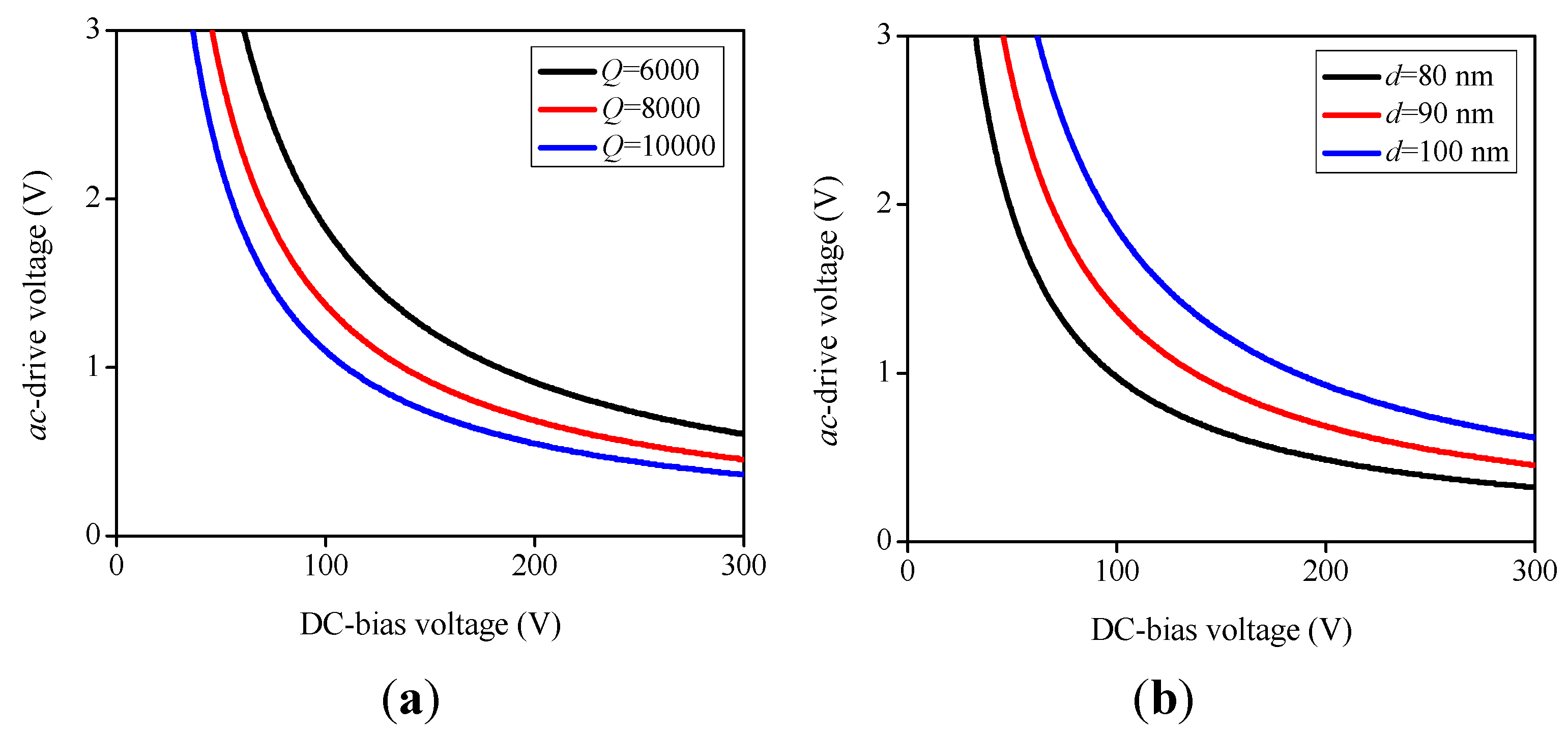
27]. However, in micromechanical ring resonators, resonant pull-in condition limits the maximum allowable quality factor and minimum initial gap spacing as shown in
Figure 6.
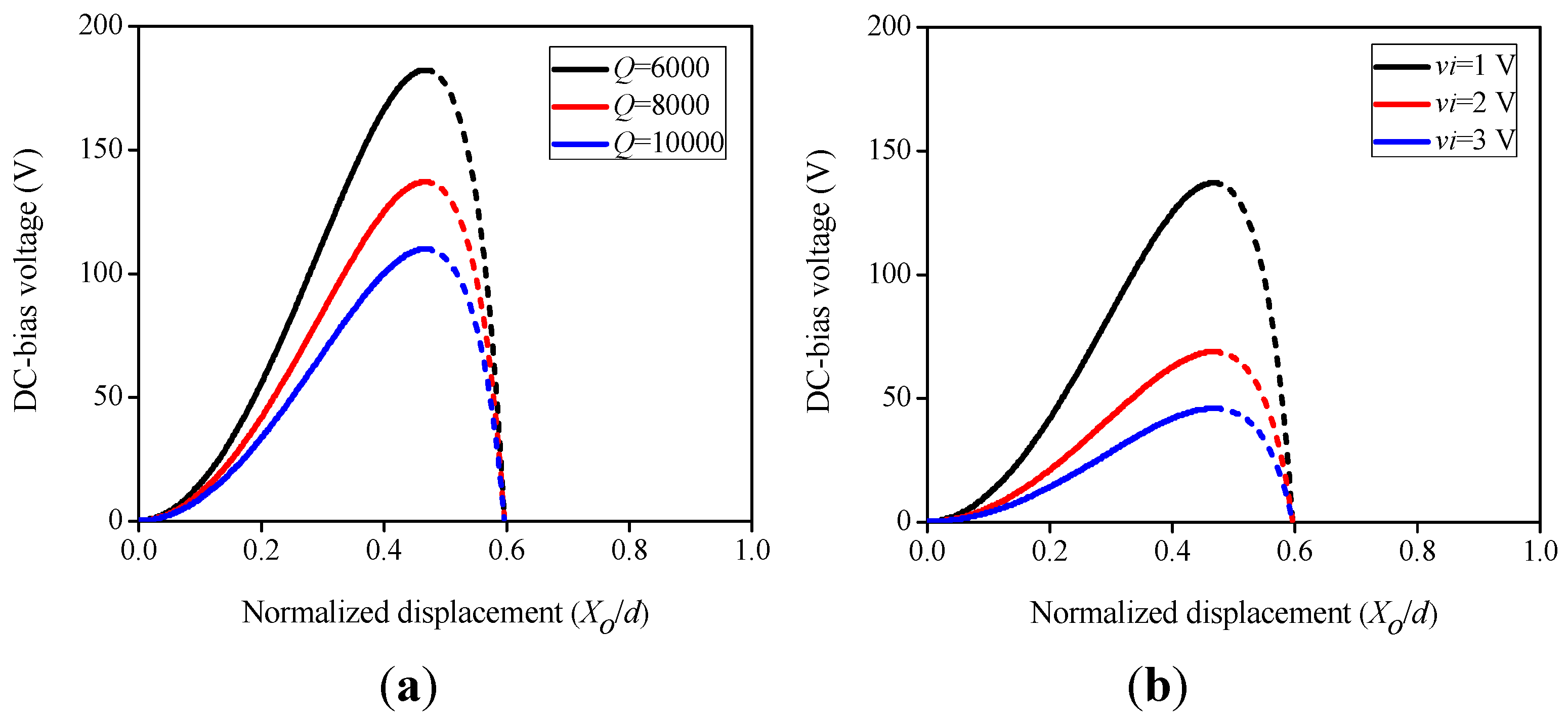
Figure 6.
Maximum combinations of ac-drive and DC-biasvoltages of EWG mode ring resonator for (a) Different values of the quality factor (with d = 90 nm); (b) Different values of the gap spacing (with Q = 8000).
Figure 6.
Maximum combinations of ac-drive and DC-biasvoltages of EWG mode ring resonator for (a) Different values of the quality factor (with d = 90 nm); (b) Different values of the gap spacing (with Q = 8000).
Figure 7.
Variation of the non-dimensional radial displacement with DC-bias voltage for EWG mode ring resonator with d = 90 nm and (a) vi = 1 V; (b) Q = 8000.
Figure 7.
Variation of the non-dimensional radial displacement with DC-bias voltage for EWG mode ring resonator with d = 90 nm and (a) vi = 1 V; (b) Q = 8000.
From
Figure 6, it is shown that the dynamic pull-in voltage (
VPI) under resonant excitation falls with the rise of
ac-drive voltage. Moreover, it can be seen that high quality factors and low gaps greatly minimize the region of stability of the ring resonator.
Figure 7 shows the relationship between the non-dimensional radial displacement of the ring resonator and the DC-bias voltage, where the solid line denotes the stable region and the dashed line denotes the unstable region.
From
Figure 7, the maximum stable displacement in the gap is independent of operating conditions and quality factor and limited to 48% of the initial gap spacing.
5.2. Nonlinear Effects on Frequency Response
To address the nonlinear effects on the frequency response, the ring resonator was excited with voltages large enough to introduce nonlinearity but, at the same time, small enough to prevent dynamic pull-in instability. Therefore, the frequency responses aid in explaining frequency instability.
In order to derive the frequency response of the ring resonator, assuming the first mode is the dominant mode and using the first-order approximation, the solution Xo(t) = Xocos(ωt) is assumed. Thus, the phase difference between the ac-drive voltage, and solution Xo(t), is maintained as the phase of applied voltage, and is fixed as the phase of solution as vi(t) = |vi|cos(ωt − φ) = v1cos(ωt) + v2sin(ωt). Substituting Equations (34) and (35) into (31) and using the method of harmonic balance, the following equations are obtained:
Substituting Equations (60) and (61) into
v12 +
v22 =
vi2 leads to the relationship between the amplitude of
ac-drive voltage and vibration amplitude. As shown in
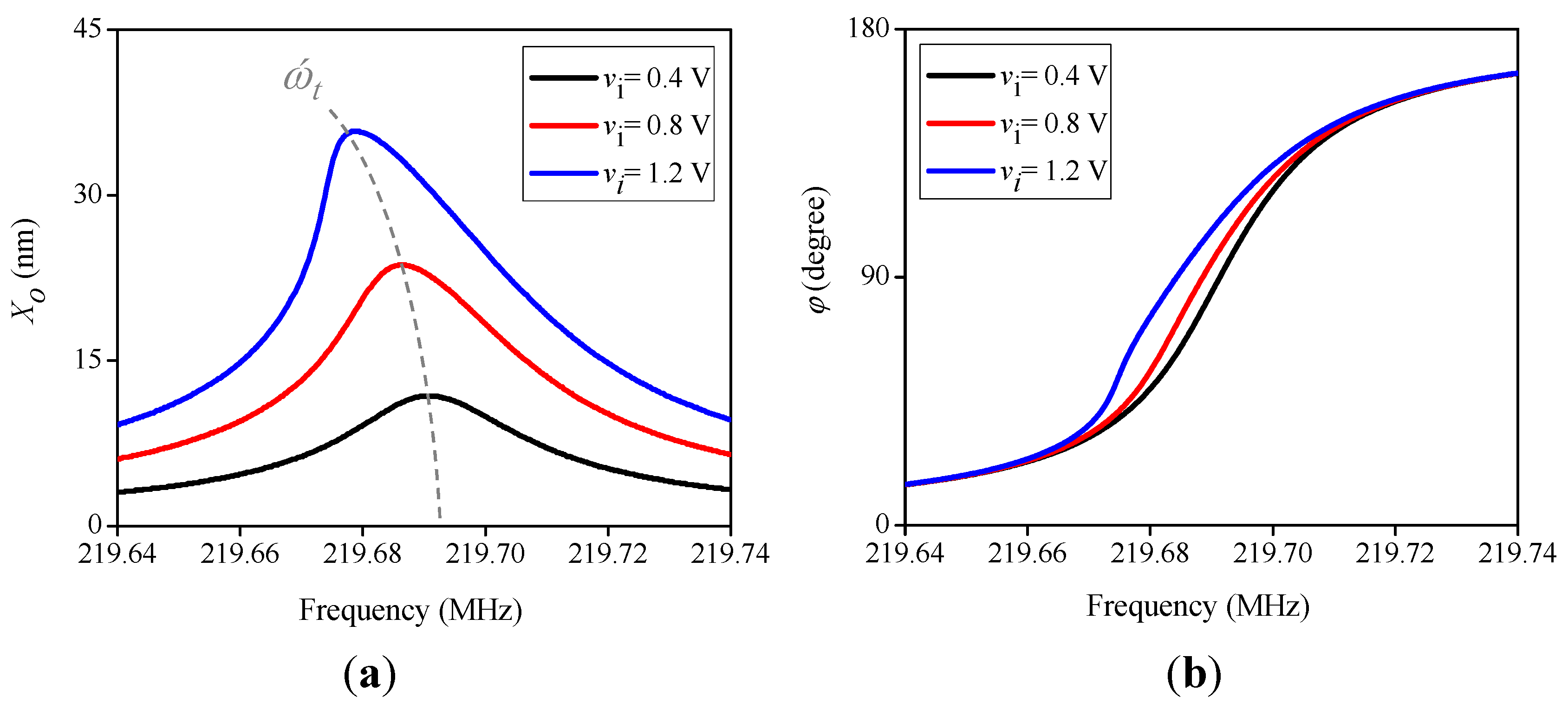
Figure 8, keeping the DC-bias voltage constant, while increasing the
ac-drive voltage (
vi), causes the peak resonance to tilt to a lower frequency, and therefore, the ring resonator exhibits a softening behavior.
Figure 8.
The effect of ac-drive voltage on frequency response for EWG mode ring resonator with Q = 8,000, d = 90 nm and VP = 100 V.
Figure 8.
The effect of ac-drive voltage on frequency response for EWG mode ring resonator with Q = 8,000, d = 90 nm and VP = 100 V.
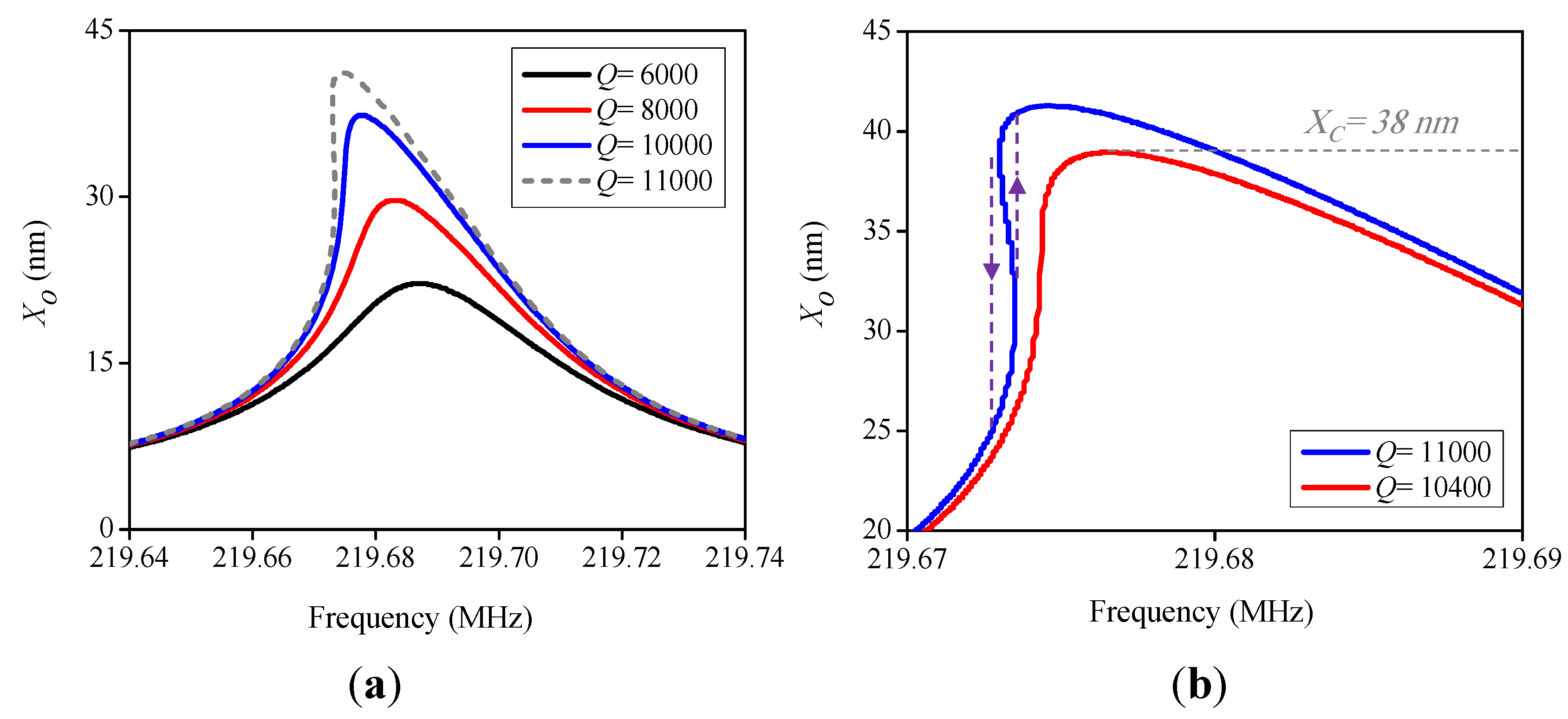
Figure 9.
(a) The effect of quality factor on frequency response for EWG ring resonator withd = 90 nm, VP = 100 V and vi = 1 V; (b) The jump phenomenon due to the frequency hysteresis at Q = 11,000.
Figure 9.
(a) The effect of quality factor on frequency response for EWG ring resonator withd = 90 nm, VP = 100 V and vi = 1 V; (b) The jump phenomenon due to the frequency hysteresis at Q = 11,000.
As shown in
Figure 9, near-resonant pull-in condition (dash line), nonlinear mechanical stiffness has a more significant effect on the frequency response, and frequency stability limits the amplitude of vibration. Therefore, the maximum amplitude predicted by resonant pull-in voltage is not reached.
The greatest vibration amplitude before hysteresis, called the critical vibration amplitude,
Xc, can be used to estimate the limit for power handling as given by
Ec = (
KmXc2)/2 [
18], where
Ec is the maximum stable energy stored in the resonator. Moreover,
Figure 9 shows that the frequency stability limits the maximum allowable quality factor.
5.3. Nonlinear Effects on Harmonic and Intermodulation Distortion
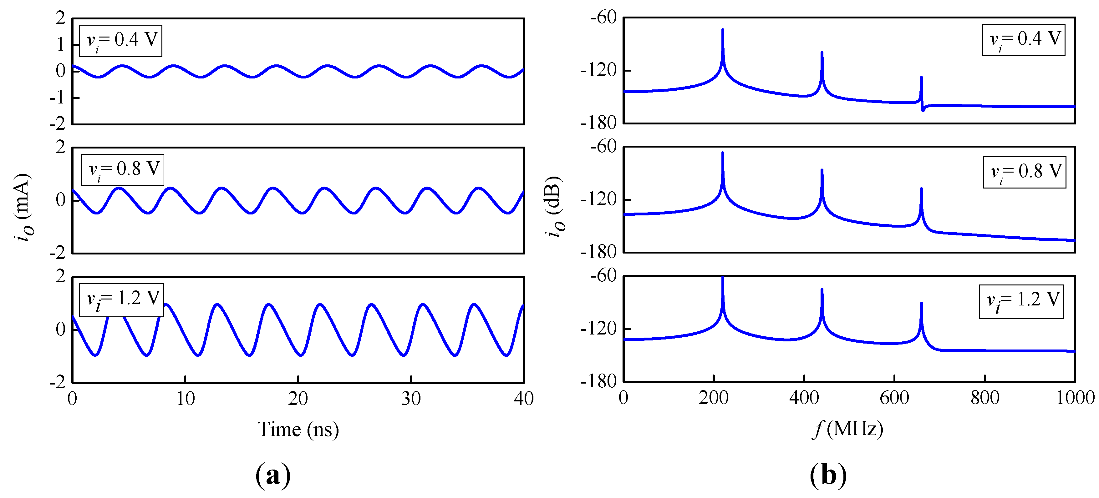
Based on Equation (51), spurious output currents are generated at the harmonic frequencies of 2ω, 3ω,..., Nω, due to mechanical and electrical nonlinearity in micromechanical resonators. To evaluate the harmonic distortions, second-order and third-order harmonic distortions (HD2 and HD3) are defined as the power ratio between second-order and third-order harmonics and the fundamental signal, respectively, as follows:
In
Figure 10, time-histories and amplitude spectrums using fast Fourier transform (FFT) are shown for different values of the product
viVP, below the resonant pull-in condition.
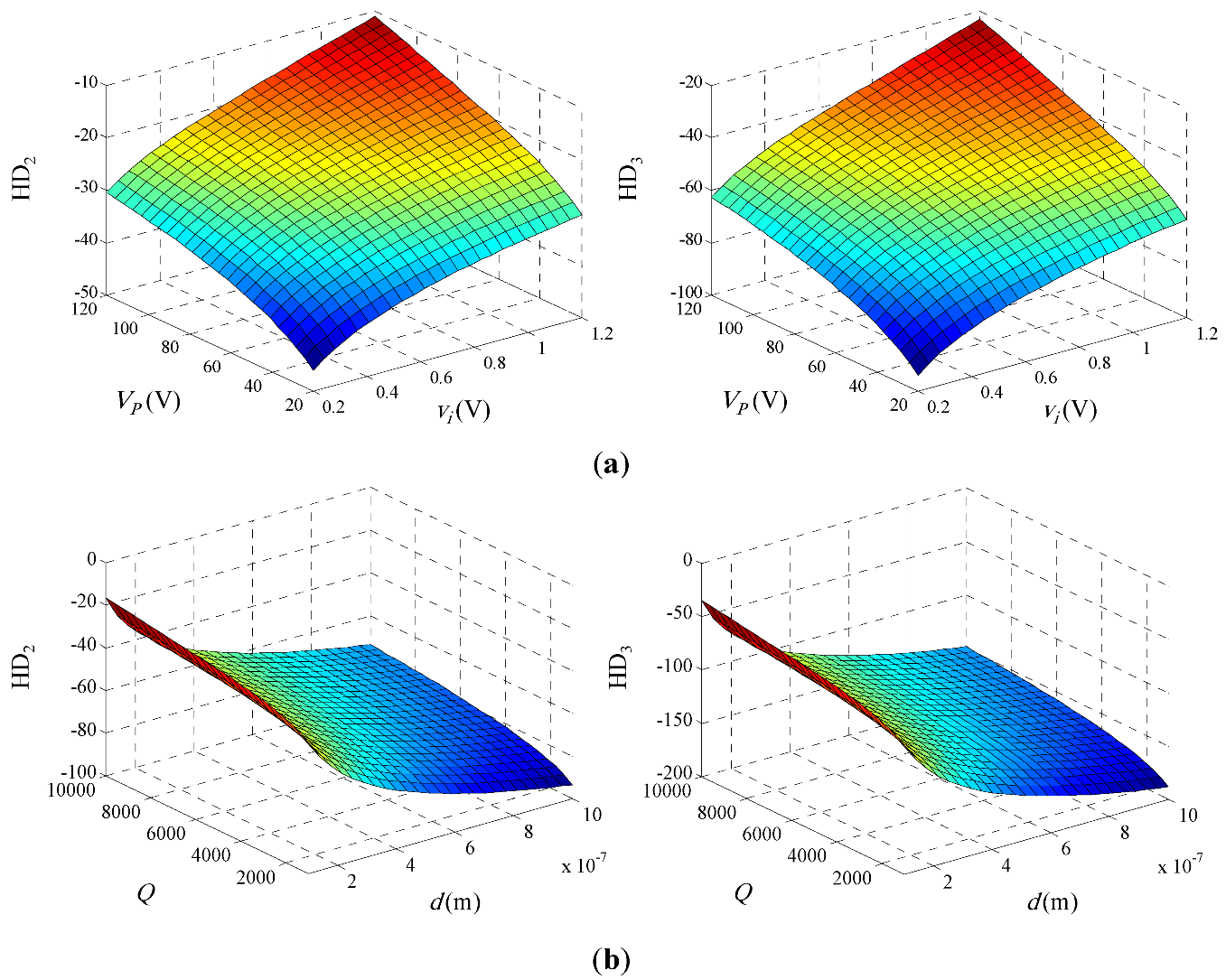
However, the evolution of HD as the operating conditions and design parameters of the bulk-mode ring resonator can be seen more clearly in
Figure 11. It can be seen that harmonic distortions increase as the
ac-drive and DC-bias voltages increase. In addition, as the quality factor increases, harmonic distortions increase, and as the initial gap spacing increases, harmonic distortions decrease.
Figure 10.
(a) The time-histories and (b) Fast Fourier transforms for EWG ring resonator with f = 220 MHz, Q = 8,000, d = 90 nm and VP = 100 V.
Figure 10.
(a) The time-histories and (b) Fast Fourier transforms for EWG ring resonator with f = 220 MHz, Q = 8,000, d = 90 nm and VP = 100 V.
Figure 11.
(a) The effect of the operating conditions on HD for EWG ring resonator with Q = 8,000 and d = 90 nm; (b) The effect of the design parameters on HD for EWG ring resonator with VP = 100 V and vi = 1 V.
Figure 11.
(a) The effect of the operating conditions on HD for EWG ring resonator with Q = 8,000 and d = 90 nm; (b) The effect of the design parameters on HD for EWG ring resonator with VP = 100 V and vi = 1 V.
A nonlinear system with multiple input frequencies, in general, contains undesired outputs at other frequencies, which are called intermodulation components. When two interferences are close to the desired channel, the third order component can fall into the channel and make it corrupt [
28].
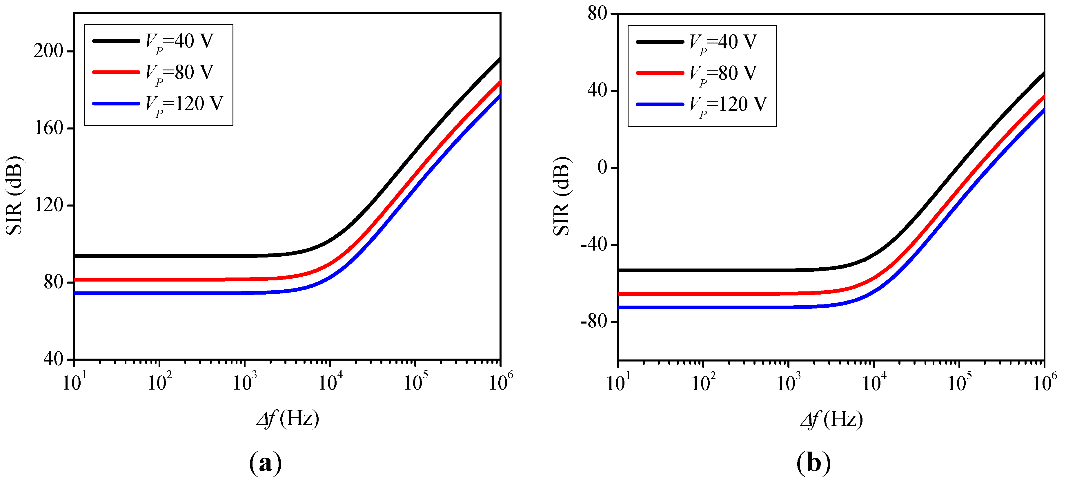
Unlike HD2 products, the presence of third-order intermodulation (IM3) products can greatly deteriorate the performance of the micromechanical filter and mixer-filter, and this indicates the importance of characterizing the IM3 in micromechanical resonators. To characterize this nonlinear behavior, a two-tone test is commonly used to calculate the signal-to-intermodulation ratio (SIR), which is defined as the ratio between the fundamental and third-order intermodulation (IM3) product of the output current as follows:
Here, the aforementioned method is applied for the input drive voltage of vint(t) = |vint|(cos(ω1t) + cos(ω2t)), at the interfering frequencies of ω1 = ωt − Δω, and ω2 = ωt − 2Δω. By using the mentioned perturbation and harmonic balance techniques, the solution of Xo0,int(t) can be obtained as:
substituting Equation (65) into the right hand side of Equation (38) and setting the secular terms to zero, the solution of Xo1,int(t) is then calculated. The total displacement due to interference signals, Xoint(t), is given by:
where
The output motional current for an infinitesimal element of the micromechanical ring resonator can be expressed as:
Multiplying by cos(2
θ) and then integrating both side from 0 to 2π, the intermodulation motional current is given by
ioIM3 =
ioint|
ω = 2ω1 − ω2. Depending on the frequency offset (Δ
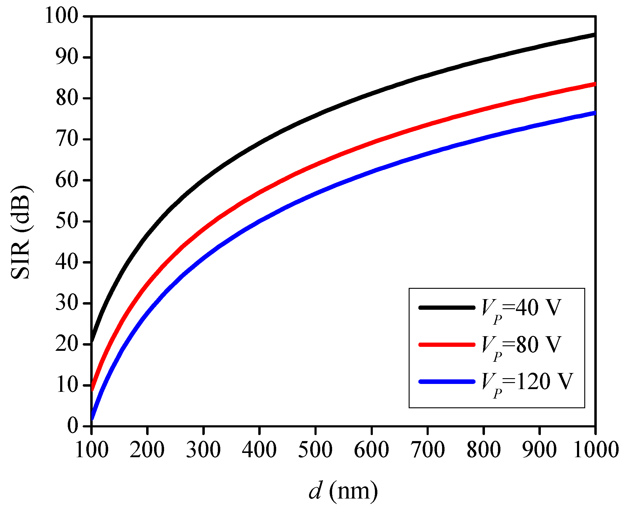
ω), the SIR values will change accordingly. The SIR was calculated at offsets between 10 Hz and 1 MHz for different values of DC-bias voltage under strong and weak interferences, as shown in
Figure 12. The analytical results predict SIR would decrease with increasing DC-bias voltage, as larger displacements generate a larger IM
3 component. Moreover, it is shown that beyond 10 kHz, mechanical attenuation outside the bandwidth of the resonator reduces the magnitude of the interferences and produces high SIR.
Figure 12.
Signal-to-intermodulation ratio (SIR) as a function of the frequency offset for EWG ring resonator with Q = 8,000, d = 90 nm and Pi = −99 dBm (a) Pint = −49 dBm; (b) Pint = 0 dBm.
Figure 12.
Signal-to-intermodulation ratio (SIR) as a function of the frequency offset for EWG ring resonator with Q = 8,000, d = 90 nm and Pi = −99 dBm (a) Pint = −49 dBm; (b) Pint = 0 dBm.
In
Figure 13, the application of the proposed model is shown for the ring resonator used as a front-end filter for Global System for Mobile Communications (GSM) standard. The intermodulation requirements indeed set the minimum value for the gap spacing. The minimum SIR level of 9 dB is considered with two 0 dBm out-of-band interferences (Δ
f = 200 kHz) [
29]. Consequently, the minimum gap spacing is found to be between 110 nm and 120 nm, depending on DC-bias voltage.
Figure 13.
Minimum gap spacing as a function of the DC-bias voltage for EWG ring resonator with Q = 8,000 and Pi = −99 dBm.
Figure 13.
Minimum gap spacing as a function of the DC-bias voltage for EWG ring resonator with Q = 8,000 and Pi = −99 dBm.
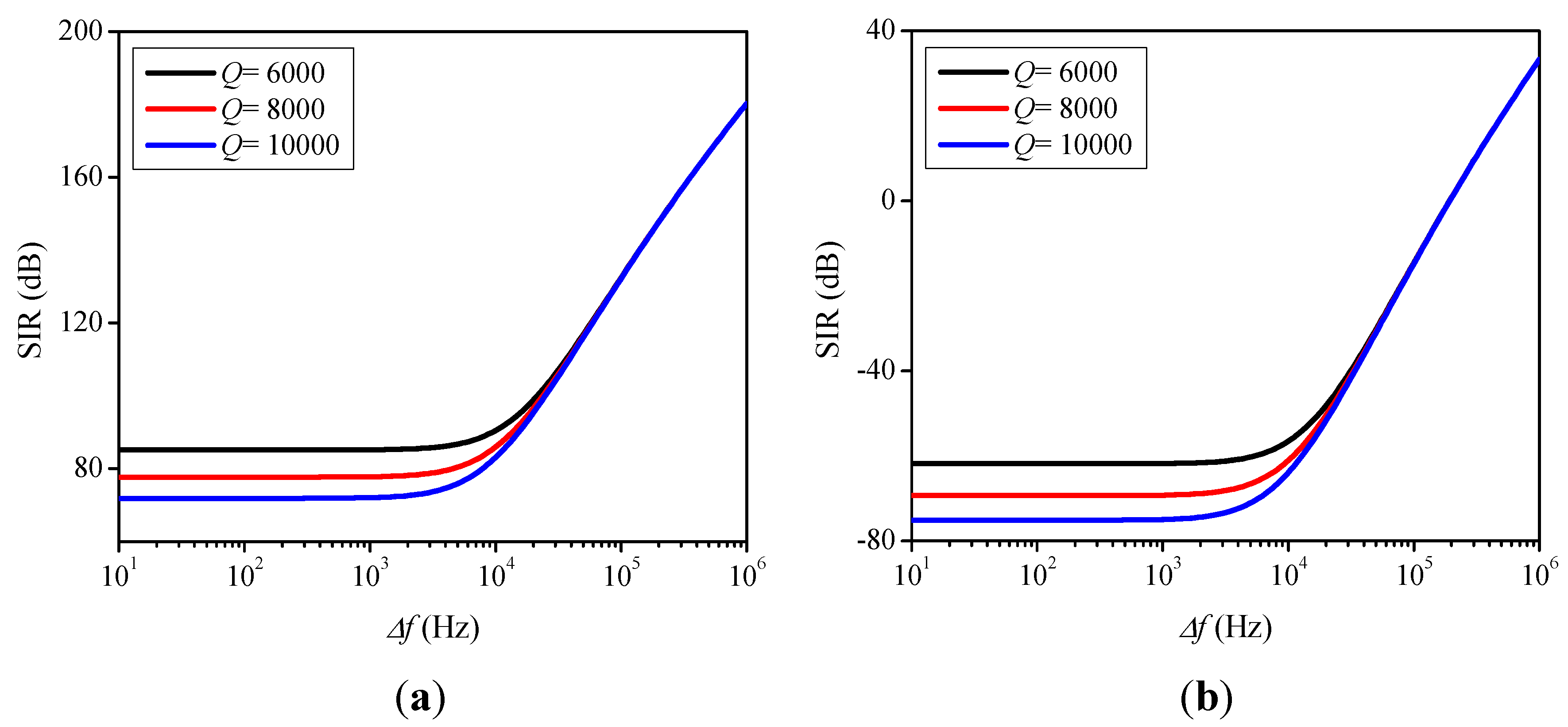
Figure 14 demonstrates the dependence of SIR on the quality factor (
Q), where the analytical results of SIR as a function of quality factor for strong and weak interferes are presented. It can be seen that, for in-band interferences, the SIR increases as the quality factor decreases. However, for out-of-band interferences, the SIR remains relatively constant with quality factor changes.
Figure 14.
Signal-to-intermodulation ratio as a function of the frequency offset for EWG ring resonator with VP = 100 V, d = 90 nm and Pi = −99 dBm (a) Pint = −49 dBm; (b) Pint = 0 dBm.
Figure 14.
Signal-to-intermodulation ratio as a function of the frequency offset for EWG ring resonator with VP = 100 V, d = 90 nm and Pi = −99 dBm (a) Pint = −49 dBm; (b) Pint = 0 dBm.


