Multi-Input Multi-Output Integrated Ionic Polymer-Metal Composite for Energy Controls

Abstract
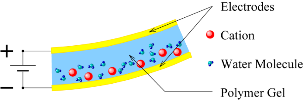
:1. Introduction


2. Experimental System and Control Model
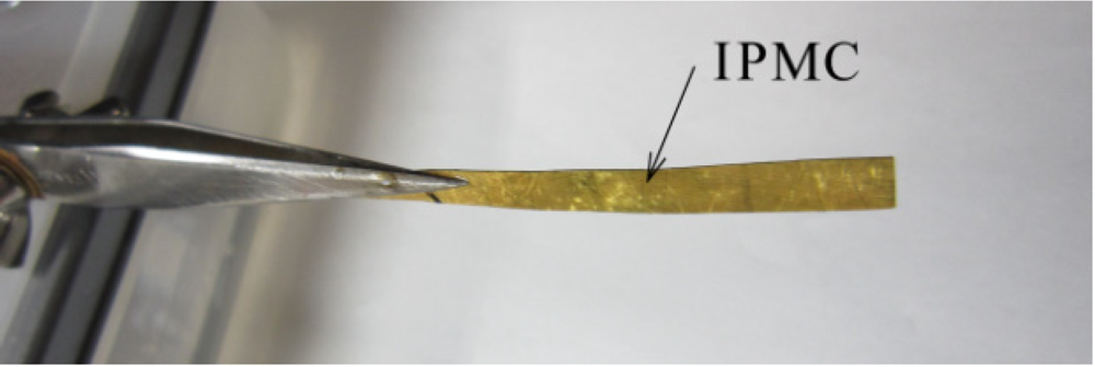
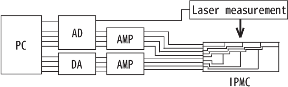
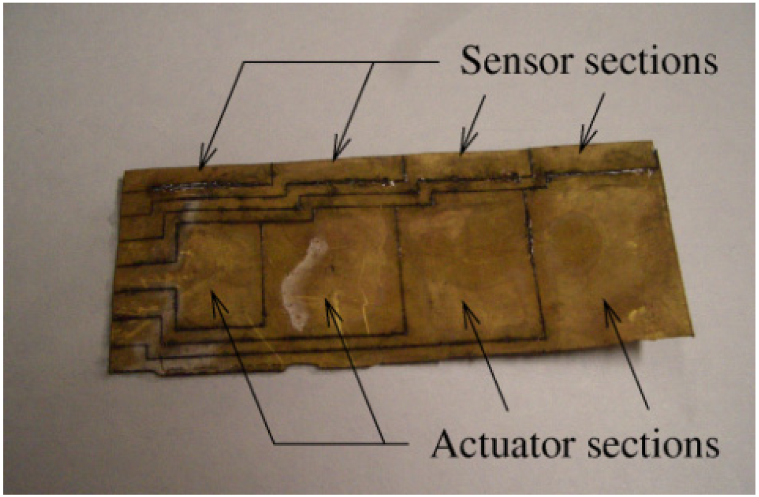
2.1. Construction of Sectioned IPMC and Experimental System
 in Figure 4. We positioned the IPMC horizontally with respect to the surface of the ground. We measured the share displacement
  vertically at each position
  for 1
for 1  with a laser measurement device to verify the sensor output of the IPMC. We assumed that the spatial difference in velocity
  for
for  would be in proportion to the output voltage
  of the
  -th sensor from the left, i.e.,
 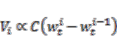 , where
  is a constant and
  . Accordingly, we can approximate the spatial partial derivatives of the share displacements from the spatial differences.
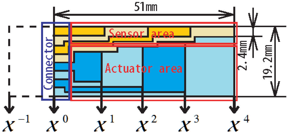

2.2. Control Model of IPMC
 , shear displacement
  , and rotation
  , and we cannot directly obtain the output with respect to the rotation from the experimental IPMC. Thus, we decided to employ the Euler-Bernoulli beam model instead as a real-time control model. The Euler-Bernoulli beam model is actually a reduced large deformation beam made by assuming
  and making a simplification [9], wherein the subscript
  means the derivative with respect to the spatial coordinate . However, we must measure (higher order) spatial derivatives of instead of .
 :
: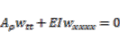 (1)
(1) is the length of the beam,
  is the mass per unit length,
  is the flexural stiffness,
  is the share displacement,
  is the time coordinate, and is the spatial coordinate. Here, the subscript of means partial derivatives with respect to or . Equation (1) can be transformed into a second order DPH system:
 (2)
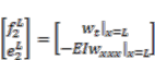
(2)  (3)
(3)  (4)
(4)  ,
,
 and (5)
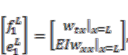
 (6)
(6)3. Control Methods and Experimental Results
3.1. Control Method I: Stabilization
 for
for  and
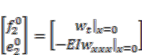
and  in Equations (5) and (6) means a collocated pair of boundary inputs and outputs for passivity-based controls. Let us consider the pair
  in Equation (5) for the IPMC. The third-order derivative of the share displacement
  at
at  can be approximated as
  , where
  is the share displacement at virtual position
  in Figure 4. We regard
  as the output
  in Equation (5). Hence, we send the feedback input
 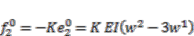 to the first actuator distributed on the interval
  , where the input voltage of the actuator is determined by
  for a constant , and
  is feedback gain. We applied a band-pass filter for
  Hz to the output voltages, because the above assumption is valid around that frequency range.
 and
and  are shown in Figure 6. The control input
  is added to the first actuator after
  . Two impact disturbances are applied to the tip of the IPMC at
  and
and  . We can see that the residual vibration in the controlled IPMC after decreases more rapidly than in the uncontrolled IPMC before this time. This means the total energy of the first term in Equation (4) is dissipated through the second and third terms in Equation (4), because the negative feedback applied to boundary variables and acts as a dissipative element.
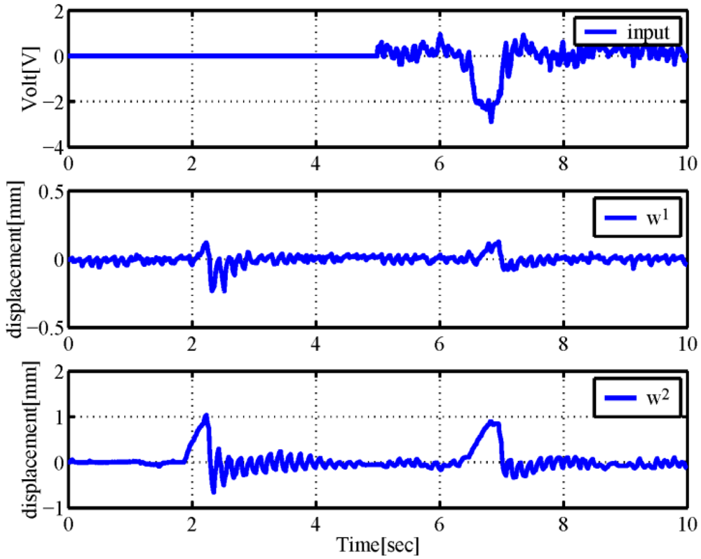
3.2. Control Method II: Detection of Dynamical Changes
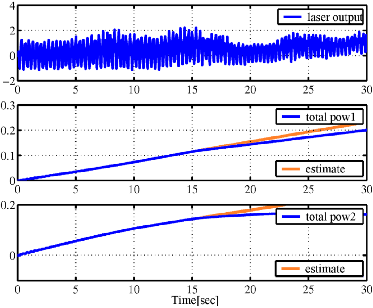
 by placing an external object after
  . The second situation was where the tip of the IPMC was soaked in water and the water level was raised after
  . We believed these environmental changes might increase the energy dissipated by the IPMC.
 (laser output), and the total boundary energy flows in the first and second sensor areas (total pow1 and total pow2) were calculated from the time integral of the product of input and output in Equation (5). The ranges of the figures have been normalized to be dimensionless. The estimated responses before the time of the change in dissipations are also plotted (estimates). , and the change in the dissipation rate can be seen as a change in the slopes of the second and third graphs. We can see from Figure 8 that a change in dissipation is detected, because dissipation constantly increases because of the viscous drag of the water after .
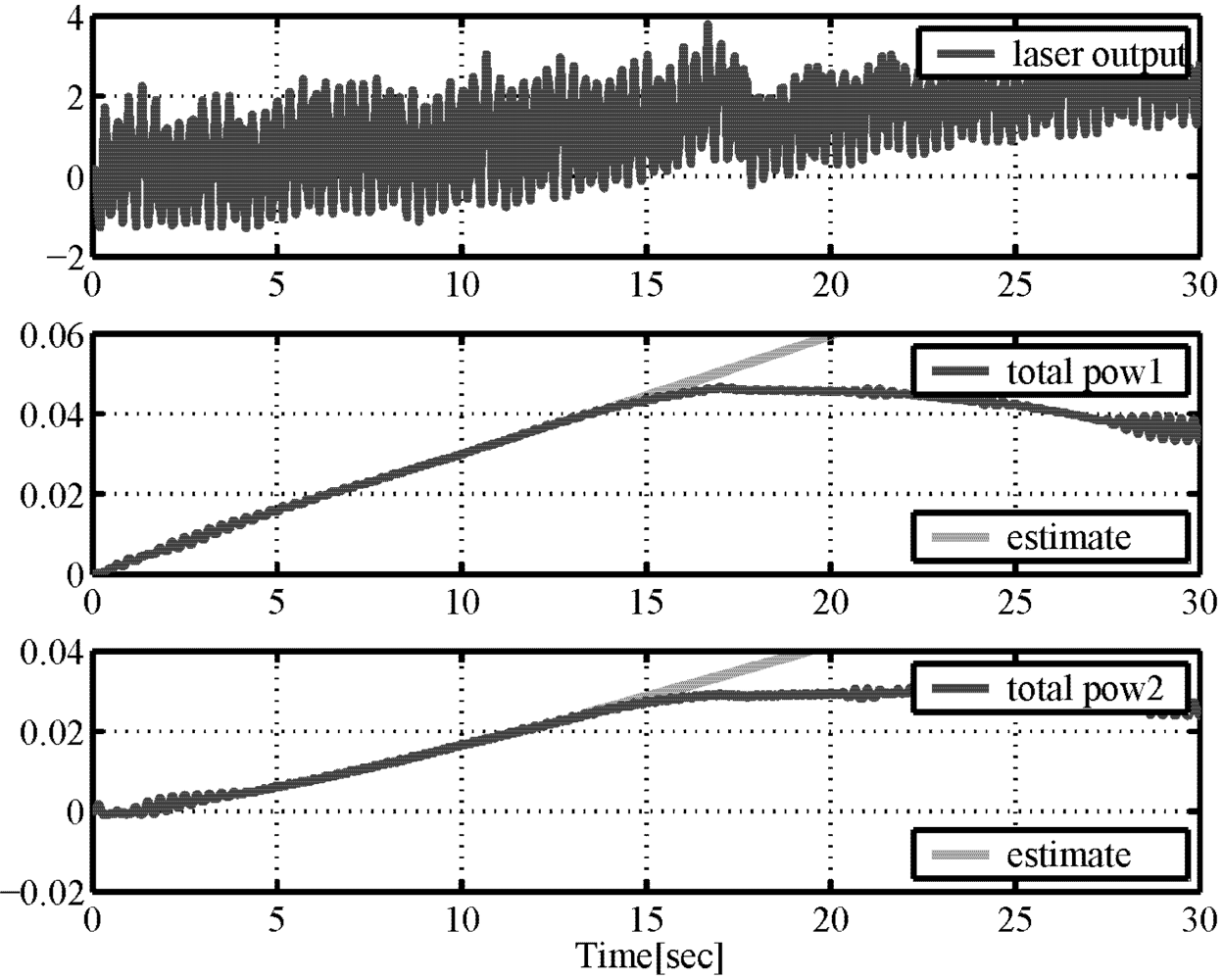
4. Conclusions
Acknowledgments
References
- Electroactive Polymer (EAP) Actuators as Artificial Muscles: Reality, Potential, and Challenges, 2nd; Cohen Y., B. (Ed.) SPIE Press: Washington, DC, USA, 2004.
- Shahinpoor, M.; Kim, K.J. Ionic polymer-metal composites: I. Fundamental. Smart Mater. Struct. 2001, 10, 819–833. [Google Scholar] [CrossRef]
- Kothera, C.; Leo, D. Bandwidth characterization in themicropositioning of ionic polymer actuators. J. Intell. Mater. Syst. Struct. 2005, 16, 3–13. [Google Scholar]
- Mallavarapu, K.; Leo, D. Feedback control of the bending response of ionic polymer actuators. J. Intell. Mater. Syst. Struct. 2001, 12, 143–155. [Google Scholar]
- Onishi, K.; Sewa, S.; Asaka, K.; Fujiwara, N.; Oguro, K. The effects of counter ions on characterization and performance of a solid polymer electrolyte actuator. Electrochim. Acta 2001, 46, 1233–1241. [Google Scholar]
- Yamaue, T.; Mukai, H.; Asaka, K.; Doi, M. Electrostress diffusion coupling model for polyelectrolyte gels. Macromolecules 2005, 38, 1349–1356. [Google Scholar]
- Bennett, M.; Leo, D. Ionic liquids as stable solvents for ionic polymer transducers. Sens. Actuat. A 2004, 115, 79–90. [Google Scholar]
- Asaka, K.; Oguro, K. Bending of polyelectrolyte membrane platinum composites by electric stimuli part II. Response kinetics. J. Electroanal. Chem. 2000, 186–198. [Google Scholar]
- Nishida, G.; Takagi, K.; Maschke, B.; Osada, T. Multi-scale distributed parameter modeling of ionic polymer-metal composite soft actuator. Control Eng. Pract. 2011, 19, 321–334. [Google Scholar]
- Van der Schaft, A.J.; Maschke, B.M. Hamiltonian formulation of distributed-parameter systems with boundary energy flow. J. Geom. Phys. 2002, 42, 166–194. [Google Scholar]
- Van der Schaft, A.J. L2-Gain and Passivity Techniques in Nonlinear Control,2nd revised and enlarged ed.; Springer Communications and Control Engineering Series, Springer-Verlag: London, UK, 2000. [Google Scholar]
- Chen, Z.; Tan, X.; Will, A.; Ziel, C. A dynamic model for ionic polymer-metal composite sensors. Smart Mater. Struct. 2007, 16, 1477–1488. [Google Scholar]
- Kim, K.J.; Tadokoro, S. Electroactive Polymers for Robotic Application: Artificial Muscles and Sensors; Springer: Berlin, Germany, 2007. [Google Scholar]
- Tiwari, R.; Kim, K.J. Improved IPMC sensing by use of cation & through induced nanoto-micro scale surface cracks. Proc. SPIE 2008, 6932, 69323H. [Google Scholar] [CrossRef]
- Nemat-Nasser, S.; Li, J. Electromechanical response of ionic polymermetal composites. J. Appl. Phys. 2000, 87, 3321–3331. [Google Scholar]
- Kamamichi, N.; Yamakita, M.; Asaka, K. A Snake-Like Swimming Robot Using IPMC Actuator/Sensor. In Proceedings of 2006 IEEE International Conference on Robotics and Automation, Orlando, FL, USA, 15–19 May 2006; pp. 1812–1817.
- Yamakita, M.; Sera, A.; Kamamichi, N.; Asaka, K. Integrated design of IPMC actuator/sensor. Adv. Robot. 2008, 22, 913–928. [Google Scholar]
- Takagi, K.; Kamamichi, N.; Stoimenov, B.; Mukai, T.; Asaka, K.; Luo, Z.-W. Frequency response characteristics of IPMC sensors with current/voltage measurements. Proc. SPIE 2008, 6927, 692724. [Google Scholar] [CrossRef]
- Shahinpoor, M.; Henderson, B.K.; Leo, D.J. Sensing capabilities of ionic polymer-metal composites. Proc. SPIE 2001, 4328, 267–274. [Google Scholar]
- Punning, A.; Kruusmaa, M.; Aabloo, A. Surface resistance experiments with IPMC sensors and actuator. Sens. Actuat. A: Phys. 2007, 133, 200–209. [Google Scholar] [CrossRef]
- Simo, J.C.; Vu-Quoc, L. On the dynamics of flexible beams under large overall motions—the plane case: Part I. J. Appl. Mech. 1986, 53, 849–854. [Google Scholar]
- Nishida, G.; Yamakita, M. A Higher Order Stokes-Dirac Structure for Distributed-Parameter Port-Hamiltonian System. In Proceedings of 2004 American Control Conference, Boston, MA, USA, 30 June–2 July 2004; 6, pp. 5004–5009.
- Gotay, M.J. A multisymplectic framework for classical field theory and the calculus of variations II: Space + time decomposition. Differ. Geom. Appl. 1991, 1, 375–390. [Google Scholar]
- Nishida, G.; Sugiura, M.; Yamakita, M.; Maschke, B.; Ikeura, R. Boundary Detection of Variational Symmetry Breaking Using Port-Representation of Conservation Laws. In Proceedings of the 48th IEEE Conference on Decision and Control, Shanghai, China, 15–18 December 2009; pp. 2861–2868.
- Nishida, G.; Maschke, B.; Ikeura, R. Discretized Hamiltonian Systems with Distributed Energy Flows on Divisible Meshe. In Proceedings of IFAC World Congress, Milano, Italy, 28 August–2 September 2011.
Appendixes
A.1. Time Variational Derivative of Hamiltonians
 of the Euler-Bernoulli beam equation:
 (A1)
(A1) is the Lagrangian of the equation, the Hamiltonian has been defined by the Legendre transformation in the multisymplectic formalism [23], and we have denoted the momentum by using the coordinate of Lagrangian systems for simplicity. The time variation in the Hamiltonian is given by
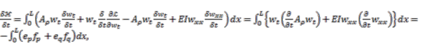 (A2)
(A2) is the variational derivative with respect to time, and the variational derivatives are regarded as partial derivatives.
A.2. Calculation of Boundary Variables
 (A3)
(A3) (A4)
(A4) .
.© 2012 by the authors; licensee MDPI, Basel, Switzerland. This article is an open-access article distributed under the terms and conditions of the Creative Commons Attribution license (http://creativecommons.org/licenses/by/3.0/).
Share and Cite
Nishida, G.; Sugiura, M.; Yamakita, M.; Maschke, B.; Ikeura, R. Multi-Input Multi-Output Integrated Ionic Polymer-Metal Composite for Energy Controls. Micromachines 2012, 3, 126-136. https://doi.org/10.3390/mi3010126
Nishida G, Sugiura M, Yamakita M, Maschke B, Ikeura R. Multi-Input Multi-Output Integrated Ionic Polymer-Metal Composite for Energy Controls. Micromachines. 2012; 3(1):126-136. https://doi.org/10.3390/mi3010126
Chicago/Turabian StyleNishida, Gou, Motonobu Sugiura, Masaki Yamakita, Bernhard Maschke, and Ryojun Ikeura. 2012. "Multi-Input Multi-Output Integrated Ionic Polymer-Metal Composite for Energy Controls" Micromachines 3, no. 1: 126-136. https://doi.org/10.3390/mi3010126
APA StyleNishida, G., Sugiura, M., Yamakita, M., Maschke, B., & Ikeura, R. (2012). Multi-Input Multi-Output Integrated Ionic Polymer-Metal Composite for Energy Controls. Micromachines, 3(1), 126-136. https://doi.org/10.3390/mi3010126