Article

W-Type Hexaferrite Film-Enabled Magnetic Resonance Engineering for Tailored Upper Stop-Band Suppression in Millimeter-Wave Bandpass Filters

1
School of Electrical and Electronic Engineering, Chung-Ang University, Seoul 06974, Republic of Korea
2
Composites Research Division, Korea Institute of Materials Science, Changwon 51508, Republic of Korea
3
Department of Intelligent Semiconductor Engineering, Chung-Ang University, Seoul 06974, Republic of Korea
4
Superintelligence Creative Research Laboratory, Material and Component Research Division, Electronics and Telecommunications Research Institute (ETRI), Daejeon 34129, Republic of Korea
*
Authors to whom correspondence should be addressed.
†
These authors contributed equally to this work.
Micromachines 2026, 17(5), 534; https://doi.org/10.3390/mi17050534
Submission received: 6 March 2026 / Revised: 17 April 2026 / Accepted: 24 April 2026 / Published: 27 April 2026
(This article belongs to the Special Issue Microwave/Millimeter-Wave Devices and Metasurfaces)

Abstract

In this study, we propose a novel approach to enhance upper stop-band attenuation in a split-ring resonator-based bandpass filter by partially inserting W-type hexaferrite films into a strategically placed mechanical hole. The hexaferrite exhibits a substantial increase in magnetic loss tangent in the desired band owing to ferromagnetic resonance, considerably improving attenuation in the upper stop-band while maintaining an acceptable insertion loss in the pass-band. The obtained results indicate that selectively placing the hexaferrite film enhances out-of-band rejection by up to 4 dB, with a slight degradation of 0.84 dB in pass-band insertion loss. Before inserting the hexaferrite film, the bandpass filter exhibited an insertion loss of 1.01 dB at 28 GHz and an attenuation of 20.04 dB at 32 GHz. By contrast, after inserting the hexaferrite film, the bandpass filter exhibited an insertion loss of 1.95 dB at 28 GHz and an attenuation of 24.45 dB at 32 GHz.

1. Introduction

Bandpass filters (BPFs) are essential components in modern wireless communication systems, radar frontends, and sensing platforms, in which these filters selectively pass desired frequency bands while suppressing unwanted signals with frequencies outside the pass band. In particular, BPFs are required for millimeter-wave applications to achieve not only low insertion loss within the pass-band, but also high attenuation in the stop-bands to mitigate interference, ensure spectral purity, and improve overall system performance.
Achieving strong out-of-band rejection ensures electromagnetic compatibility and maintains signal integrity in high-frequency systems. Inadequate attenuation in the stop bands can generate unwanted spurious emissions, harmonic distortion, and adjacent channel interference, all of which degrade system performance and violate regulatory spectral masks. These are particularly problematic in densely packed frequency environments such as those involving 5G and satellite communications, in which multiple systems coexist within close spectral proximity. Therefore, improving the stop-band attenuation of BPFs is essential for satisfying system-level specifications, complying with international communication standards, and minimizing crosstalk in multi-channel transceivers.
High-performance BPFs, owing to their high speed and low latency characteristics, are essential for 5G applications at the 28 GHz band, a primary frequency band for 5G millimeter-wave deployment [1,2,3,4]. Filters operating in this regime must be compact and compatible with highly integrated modules and maintain low insertion loss (typically < 2 dB) and sharp frequency selectivity to suppress interference from adjacent channels.
However, filter design for millimeter-wave applications encounters several challenges, including high conductor and dielectric losses and high sensitivity to fabrication tolerances [5,6]. Furthermore, achieving high selectivity often requires complex, high-order designs, necessitating large circuits and high tuning complexity [7,8] while deteriorating insertion loss [7].
As a result, there is a growing need for alternative approaches that can achieve strong stop-band attenuation without sacrificing size, manufacturability, or critical filtering performance such as insertion loss. To meet these demands, investigations into numerous filter technologies have been conducted, including low-temperature co-fired ceramic (LTCC) BPFs [9,10,11,12,13,14,15,16], on-chip BPFs [17,18,19,20,21], substrate integrated waveguide (SIW) BPFs [22,23,24,25,26,27,28], and microelectromechanical systems (MEMS)-based BPFs [29,30,31,32,33]. However, these approaches often encounter inherent trade-offs regarding circuit footprint, fabrication cost, and integration complexity [34,35]. Relying on conventional circuit-based structural modifications inevitably increases the physical size. This highlights the need for a paradigm shift toward material-based solutions that can selectively suppress undesired bands without expanding the circuit footprint. Addressing this research gap, this study proposes a fundamentally different approach by utilizing the engineered magnetic resonance of W-type hexaferrite films to achieve targeted upper stop-band suppression. The key idea involves exploiting ferromagnetic resonance (FMR), a frequency-selective magnetic loss phenomenon, as a design variable within the filter architecture. We embedded the ferrite film into a split-ring resonator (SRR)-based BPF, which exhibits a high electromagnetic-field concentration within the ring structure [36,37,38,39,40,41,42]. The interaction between the concentrated magnetic field and the ferrite film is maximized, considerably attenuating the upper stop band.
W-type hexaferrite (BaMe2Fe16O27, where Me is a transition metal) is categorized as a hexagonal ferrite, distinguished by strong uniaxial anisotropy along the c-axis. This intrinsic anisotropic characteristic yields pronounced FMR and high magnetic losses in the gigahertz frequency range, rendering W-type ferrites attractive candidates for various high-frequency applications [43]. As the resonance frequency of FMR is proportional to the magnitude of the anisotropy field (Ha), tailoring the anisotropy field of W-type ferrites frequency-selective magnetic loss responses. Among the approaches investigated for tunable magnetic anisotropy, substituting transition metals for Fe sites has proven to be the most effective and simple strategy for controlling the anisotropy field. In this study, Ni–Co-substituted Ba-W hexaferrite films were fabricated, and the relative amounts of Ni and Co were adjusted to achieve the targeted FMR behavior at the 5G frequency band. The implementation of the hexaferrite films introduce a new aspect of filter design, enabling the precise adjustment of out-of-band rejection by manipulating the magnetic loss profile, rather than relying solely on structural complexity. The proposed strategy combines the electromagnetic concentration capabilities of SRR structures with the FMR of W-type hexaferrite films, offering a compact, integrable, and customizable solution for application in next-generation millimeter-wave filtering systems, particularly in the 28-GHz band.
To validate this approach, W-type hexaferrite films were partially inserted into strategically placed mechanical holes within the SRR-based BPF. Consequently, the magnetic loss tangent of the hexaferrite increased remarkably within the target frequency range owing to FMR, thus considerably improving upper stop-band attenuation while preserving acceptable pass-band performance. Experimental results revealed that the selective placement of the ferrite film enhanced out-of-band rejection by up to 4 dB, with only a minor increase of 0.84 dB in insertion loss. Specifically, the insertion loss at 28 GHz increased from 1.01 dB to 1.95 dB, whereas attenuation at 32 GHz improved from 20.04 dB to 24.45 dB after inserting the hexaferrite film. These results confirm the practical viability of magnetic-resonance-assisted filter design in achieving application-specific suppression in the millimeter-wave regime.

2. Design and Simulation

2.1. Split-Ring Resonator-Based BPF

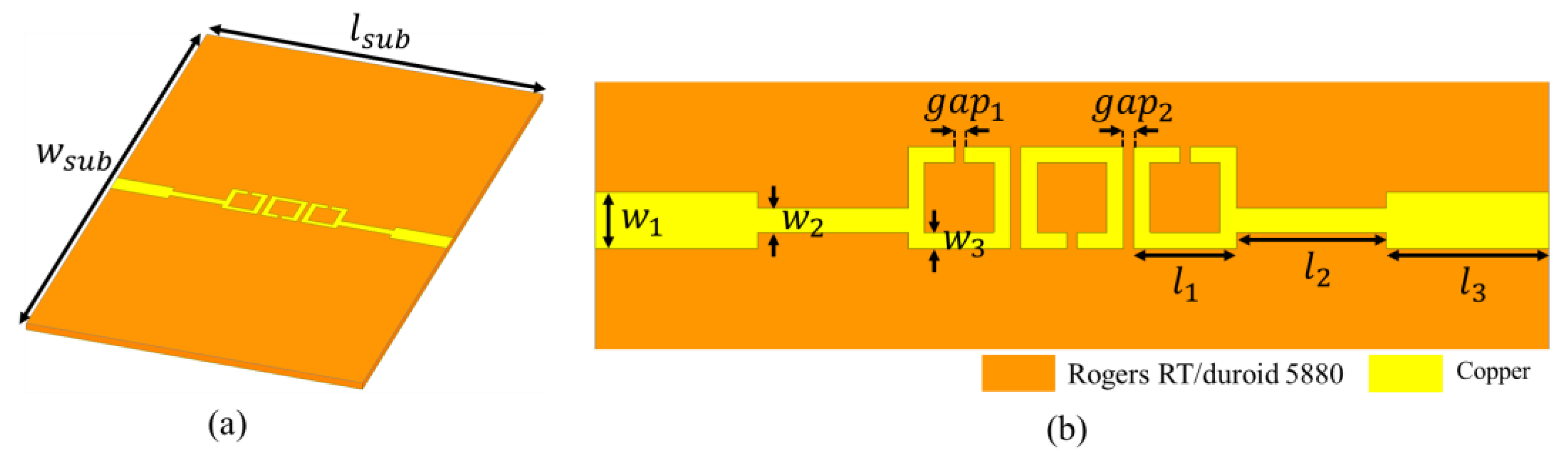
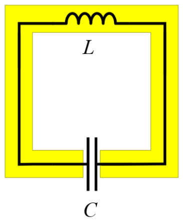
In this paper, we present a third-order SRR-based BPF, operating in the millimeter-wave band as shown in Figure 1. The substrate for the proposed filter is Rogers RT/duroid 5880 with a dielectric constant of 2.2, loss tangent of 0.0009, and thickness of 0.25 mm was used to fabricate the proposed BPF. The thickness of both the top and the bottom metal layers was 0.018 mm. The BPF was designed and simulated using the Ansys high-frequency structure simulator (HFSS) and the simulation applied the finite element method (FEM). Each ring was split, introducing a capacitive element to the structure [36,37,38,39]. An effective inductance (L) and effective capacitance (C) are formed, as shown in Figure 2 [44].
The combination of the inductance and the split-induced capacitance of the ring determined the resonant frequency of the SRR as follows:
f = 1 2 π LC .
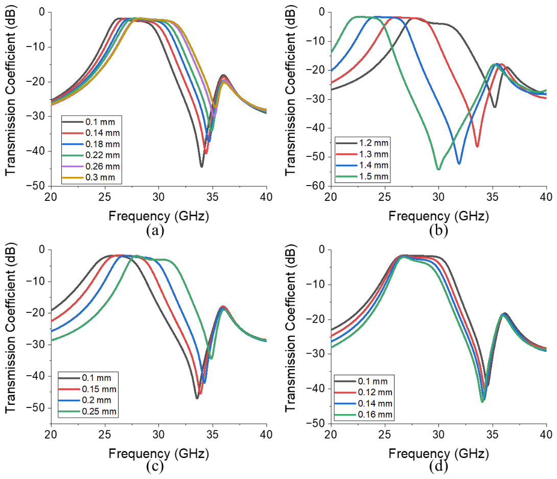
The capacitance increased when g a p 1 decreased, and the inductance increased when l 1 increased or w 3 decreased. This LC resonance behavior is confirmed through simulations, as depicted in Figure 3, which presents the simulated transmission coefficients obtained by varying the geometrical parameters of the filter illustrated in Figure 1b. Figure 3a, Figure 3b and Figure 3c present the transmission coefficients corresponding to the ranges of g a p 1 (0.1–0.3 mm), l 1 (1.2–1.5 mm), and w 3 (0.1–0.25 mm) values, respectively. The figures reveal that decreases in g a p 1 and w 3 and increases in l 1 decrease the size of the bandpass region. For example, as g a p 1 and w 3 decreases, the size of the bandpass region decreases from 4.97 GHz ( g a p 1 = 0.3 mm) to 4.17 GHz ( g a p 1 = 0.1 mm), and 4.39 GHz ( w 3 = 0.25 mm) to 3.9 GHz ( w 3 = 0.1 mm), respectively. In addition, as l 1 increases from 1.2 mm to 1.5 mm, the size of the bandpass region decreases from 4.36 GHz to 3.44 GHz. Moreover, Figure 3d presents the transmission coefficients corresponding to a range of g a p 2 values (0.1–0.16 mm), revealing that as g a p 2 increases, magnetic coupling decreases [38], which, in turn, increases insertion loss from 1.71 dB ( g a p 2 = 0.1 mm) to 3.26 dB ( g a p 2 = 0.16 mm) at 28 GHz and decreases bandwidth from 5.26 GHz ( g a p 2 = 0.1 mm) to 3.42 GHz ( g a p 2 = 0.16 mm), respectively. Based on these analysis results, the final dimensions of the proposed BPF were determined as follows: l s u b = 11.74 mm, w s u b = 18.9 mm, l 1 = 1.26 mm, l 2 = 1.85 mm, l 3 = 2 mm, w 1 = 0.7 mm, w 2 = 0.3 mm, w 3 = 0.2 mm, g a p 1 = 0.125 mm, and g a p 2 = 0.13 mm (Figure 1).
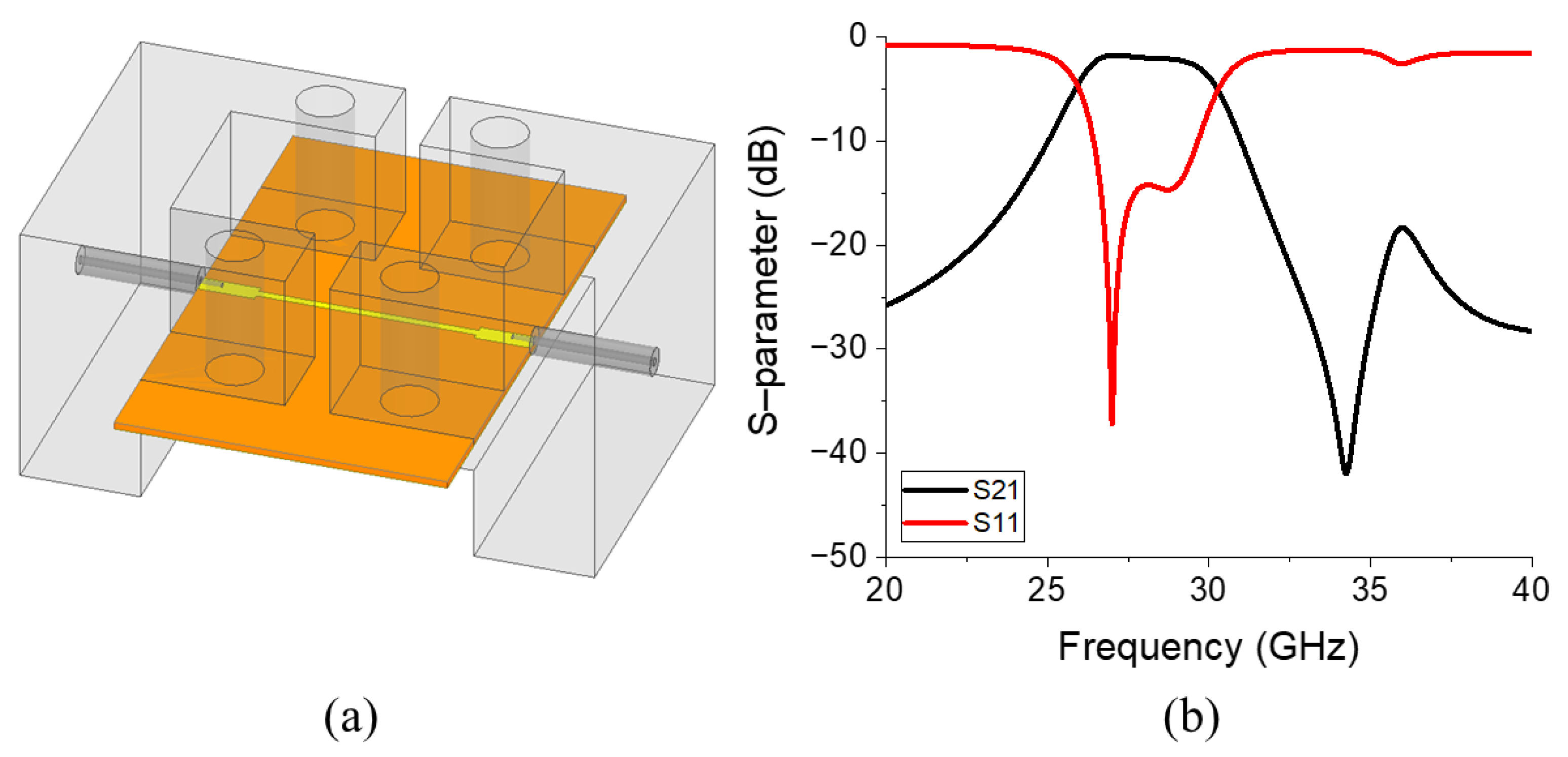
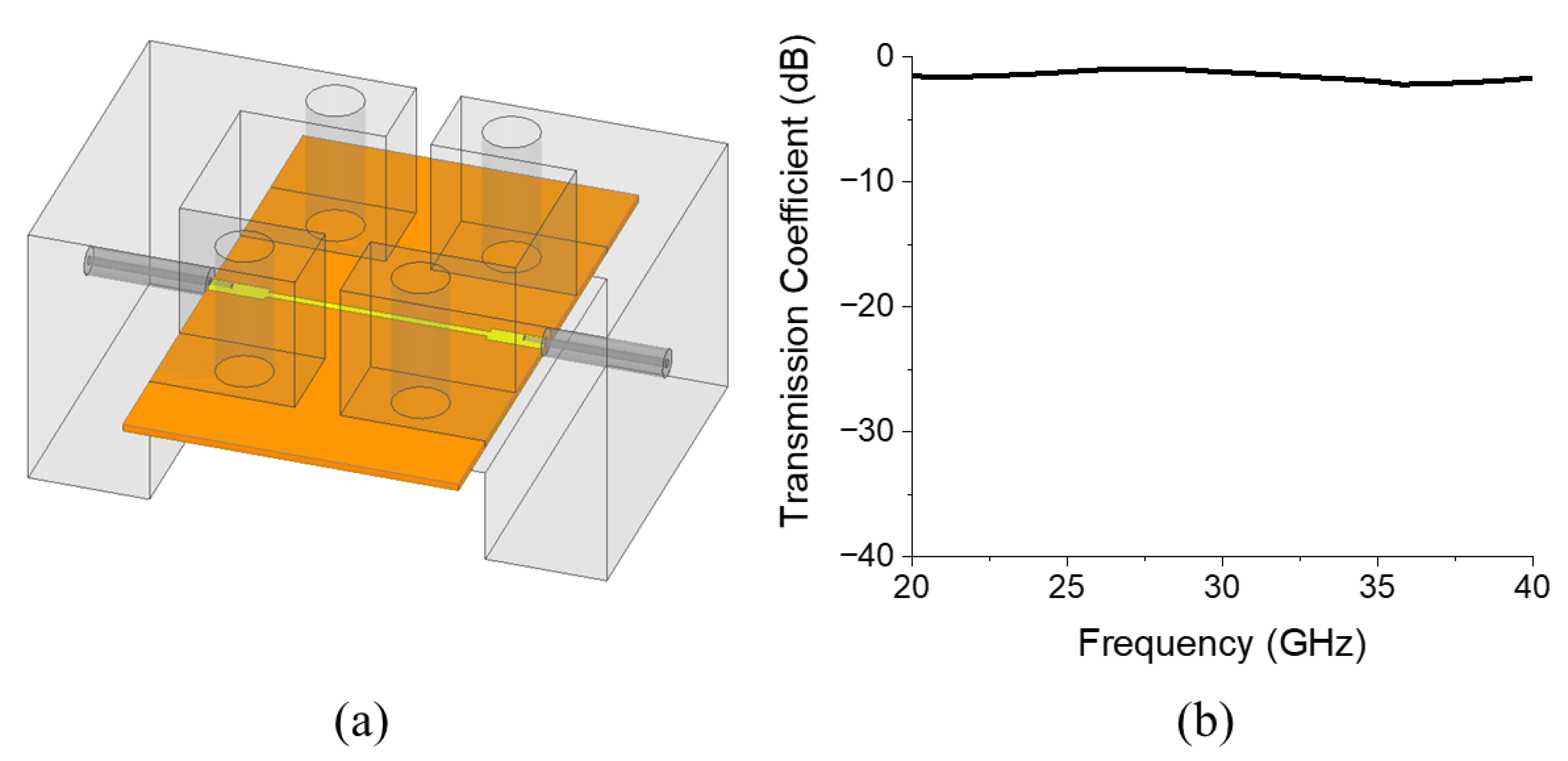
The simulation setup of the proposed BPF, including connectors, is displayed in Figure 4a, and the simulated S-parameters are displayed in Figure 4b. To eliminate the insertion loss generated by the transmission line outside the SRR section, including the connectors, a reference transmission line structure is designed, as depicted in Figure 5a. Figure 5b reveals that the insertion loss of this reference transmission line is 0.94 dB at 28 GHz. By subtracting this insertion loss value, the actual insertion loss of the proposed BPF was obtained as 1.02 dB at 28 GHz, and the upper stop band attenuation of the filter was 18.11 dB at 32 GHz.

2.2. W-Type Hexaferrite Film

W-type hexaferrite has a general chemical formula of BaMe2Fe16O27 (where Me is a transition metal) and a crystallographic structure consisting of R (BaFe6O11) and S (2(MeFe2O4)) blocks stacked in the sequence RSSR*S*S*, where R* and S* blocks are 180° rotated versions of the R and S blocks, respectively. In particular, the R block possesses hexagonal symmetry, which, in turn, imparts the W-type ferrite with a hexagonal crystal structure. This crystallographic characteristic plays a crucial role in determining intrinsically high magnetic anisotropy of W-type ferrites. Such high anisotropy is the origin of FMR, in which the precessional motion of magnetization resonates with the incident electromagnetic wave, generating magnetic losses in the gigahertz frequency range. The resonance frequency of FMR (fFMR) is proportional to the Ha of the material, as expressed in the following relation:
f F M R = γ 2 π H a = 1.4 g H a ,
where γ represents the gyromagnetic ratio and g is the Lande g-factor [45]. The W-type ferrite must exhibit low magnetic losses within the pass-band while providing high magnetic losses in the upper stop-band for application in BPFs. Therefore, the frequency response of the complex permeability, governed by the FMR, should be carefully tailored by appropriately designing the anisotropy field. The anisotropy field of a W-type ferrite is influenced by several factors, including (1) shape anisotropy, (2) lattice parameters, and (3) Fe sublattice occupancy within the crystal structure. Consequently, precise compositional and processing control is required to achieve the desired performance.
In addition to magnetic losses, a low dielectric loss must be maintained across the operating frequency range to preserve the low insertion loss in the pass band. As W-type ferrites are insulating oxides, they generally exhibit low dielectric losses; however, the coexistence of Fe2+ and Fe3+ generates higher dielectric losses than M-type ferrites, which are solely composed of Fe3+ [46]. Therefore, to minimize dielectric losses, compositional design strategies involving transition-metal substitution must be accompanied by optimized calcination conditions that suppress Fe2+ formation.
Ni2+-substituted Ba-W ferrite was selected as the candidate material, and Co2+ was partially substituted for Ni2+ to tailor the FMR frequency to simultaneously achieve (1) high magnetic loss in the upper stop band owing to FMR and (2) low dielectric loss across the entire band [47]. Previous studies have demonstrated that BaNi2Fe16O27 exhibits strong FMR-induced magnetic losses around 40 GHz, while half-substitution of Co2+ shifts the resonance frequency downward by nearly 10 GHz. Furthermore, a linear correlation was identified between fFMR and the Co2+ substitution content, as expressed in the following relationship:
f F M R ( G H z ) = 37.49 − 31.76 ( x ) ,
where ( x ) represents the substitution composition of Co ions in the BaNi2−xCoxFe16O27 system. Based on this relation and considering the FMR bandwidth of W-type ferrites, the Co substitution level of 0.1 was considered to induce magnetic losses starting at approximately 30 GHz and produce the maximum imaginary permeability near 35 GHz, corresponding to strong magnetic attenuation in the upper stop-band. Accordingly, we selected BaNi1.9Co0.1Fe16O27 as the target composition, synthesized the optimized Ba(W) ferrite powder via controlled calcination, and subsequently fabricated the hexaferrite film applied in this study by using this powder.

2.3. BPF with the Hexaferrite Film

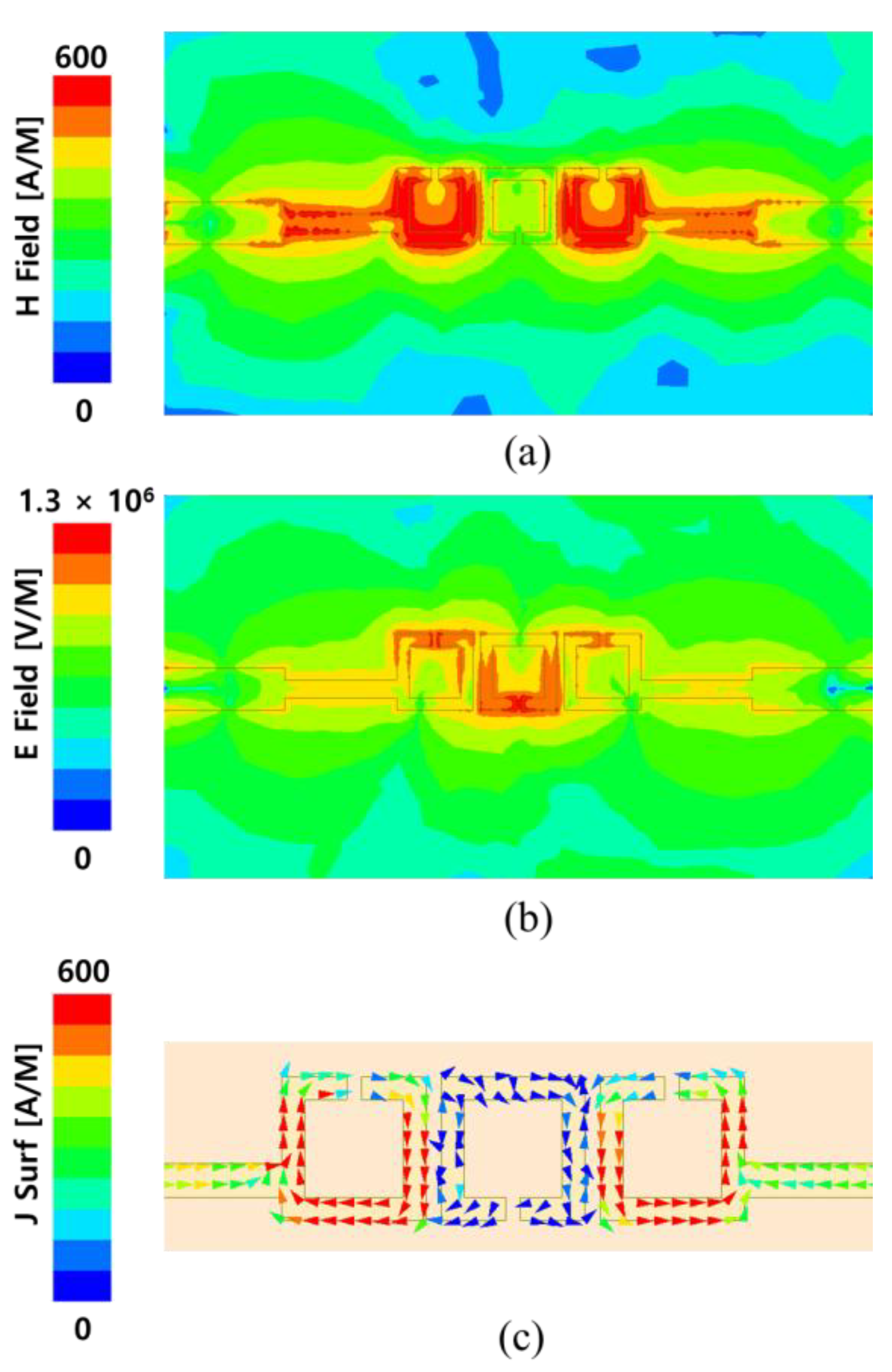
To improve attenuation in the upper stop band, the proposed BPF was first analyzed near the beginning of the stop-band region. Based on the 3-dB cut-off frequency of 30.6 GHz, the electromagnetic-field distribution was examined at 29.9 GHz, which is slightly below the cut-off. Figure 6a indicates that the magnetic field is concentrated in the first and third rings, whereas the electric field is primarily concentrated in the second ring, as depicted in Figure 6b. Furthermore, the surface current analysis shown in Figure 6c indicates a circular current flow, inducing a strong magnetic field inside the ring structure [35].
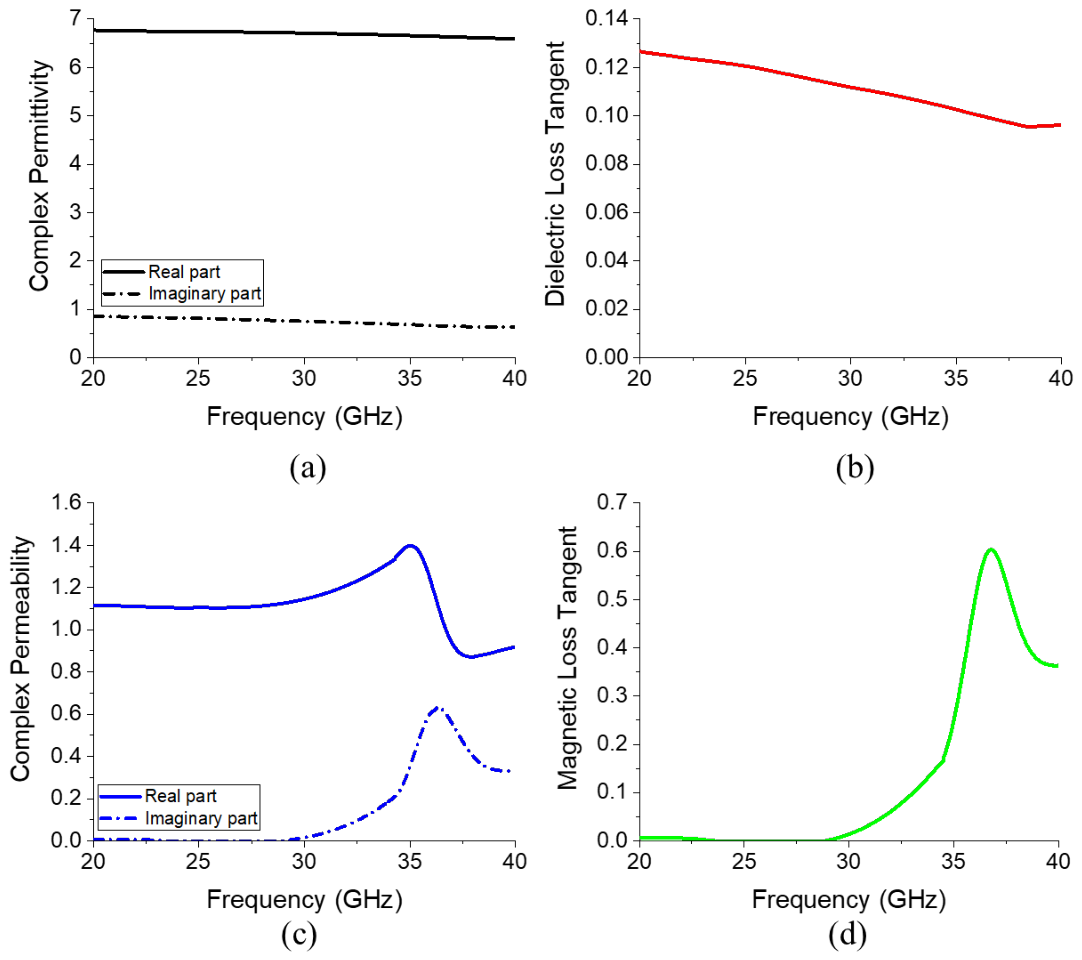
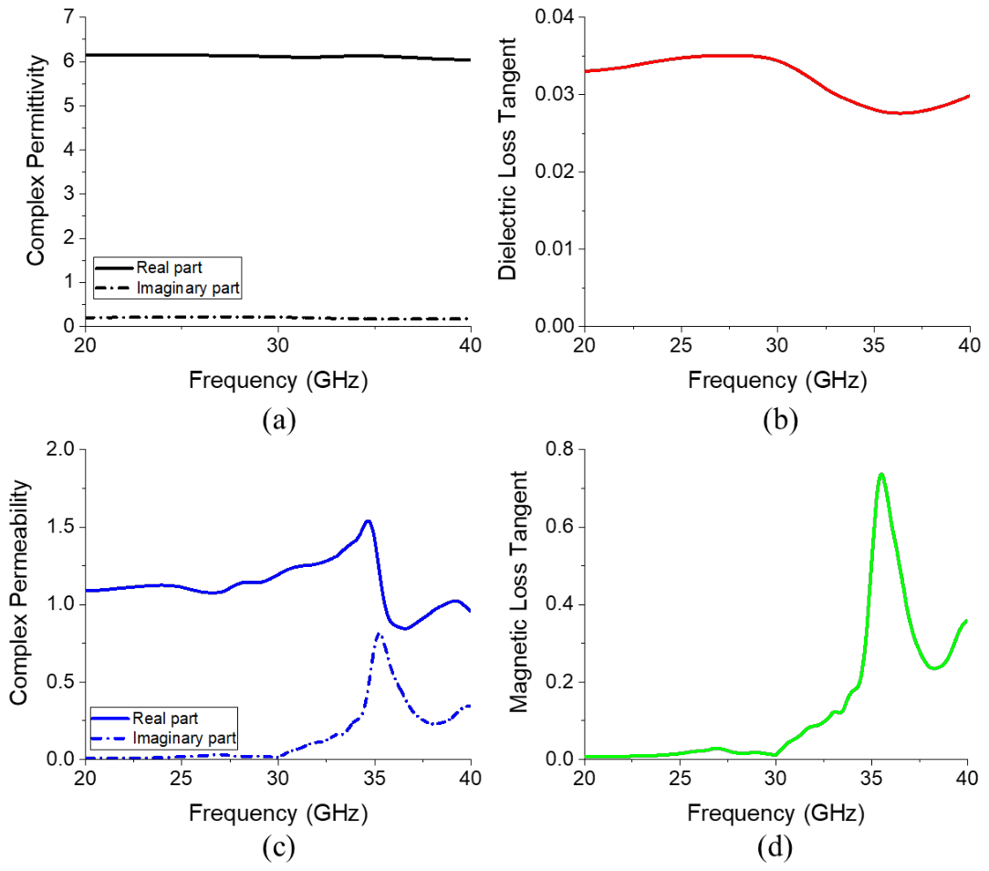
Before inserting the ferrite film at the location where the magnetic field is concentrated, the electromagnetic characteristics of the ferrite film are defined, as shown in Figure 7. To enhance attenuation in the upper stop band, the magnetic loss tangent is configured to begin increasing around 30 GHz, as illustrated in Figure 7d. The frequency-dependent electromagnetic properties of the ferrite film were modeled and assigned in Ansys HFSS using the frequency-dependent material setup.
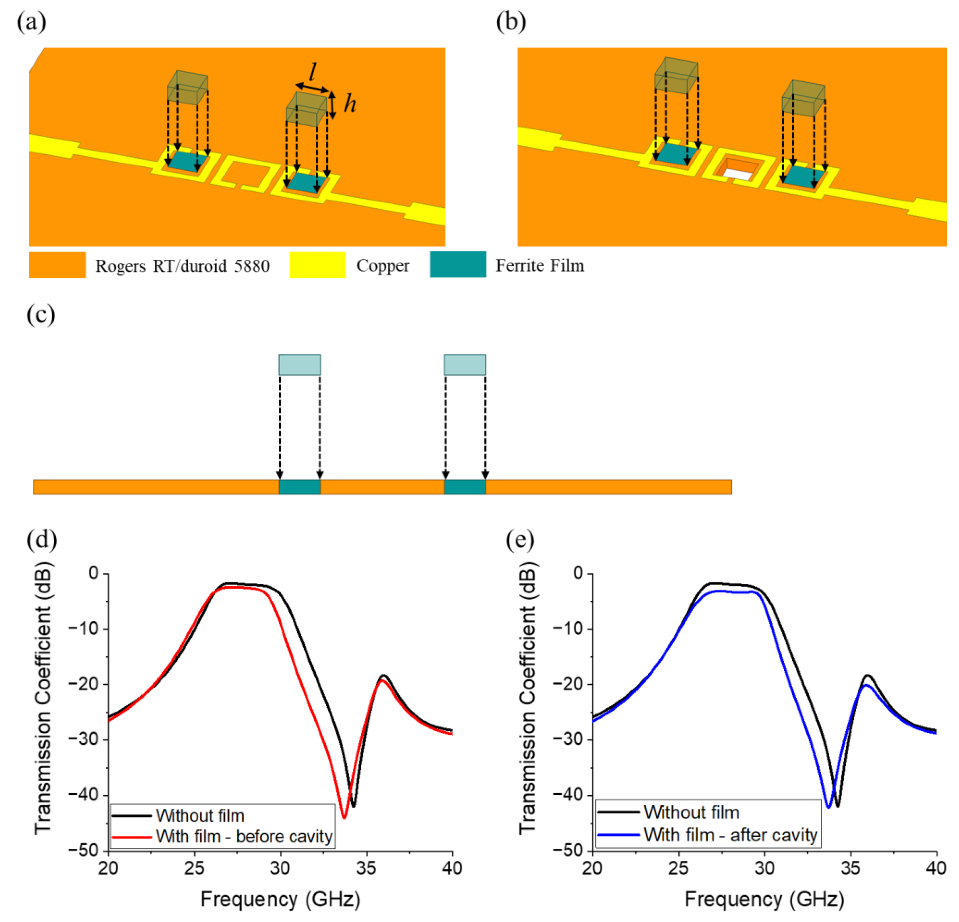
In the first attempt, ferrite films with lateral dimensions of 0.7 mm and a height of 0.25 mm are inserted into the first and third rings, as displayed in Figure 8a, thereby reducing the bandwidth, as shown in Figure 8c. To address this issue, we refer to the electric-field distribution displayed in Figure 6b and form an air cavity in the region where the electric field is concentrated, as illustrated in Figure 8b. This modification effectively lowered the relative permittivity in the region influenced by the electric field, thereby mitigating the bandwidth reduction. Therefore, the reduced bandwidth is compensated for and attenuation is improved, as shown in Figure 8d [48]. Based on this analysis, the structural configuration was determined such that the ferrite films can be inserted into the first and third rings, and a mechanically formed air cavity can be included in the second ring. The specific dimensions of the ferrite films, however, were not finalized at this stage. To optimize the performance of the BPF, i.e., to maximize stop-band attenuation while minimizing the impact on pass-band insertion loss, a parametric study was subsequently conducted to determine the optimal lateral and vertical dimensions of the ferrite films. In addition to the physical dimensions, the electromagnetic properties of the ferrite film were only partially defined at this stage. These frequency-dependent characteristics require additional analysis and optimization to ensure that the desired filtering performance is attained.
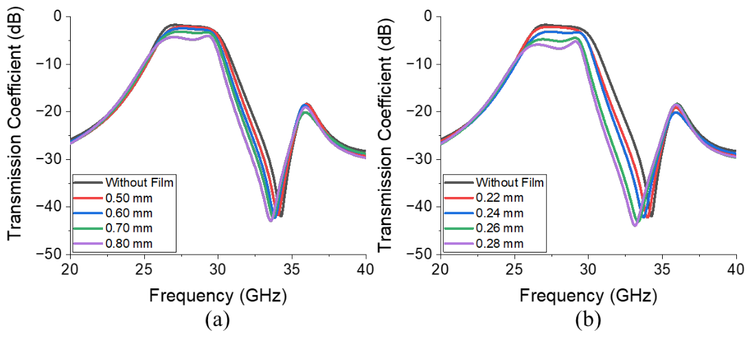
A parametric study is conducted to determine the physical dimensions, l and h , of the ferrite film shown in Figure 8a. Figure 9a presents the transmission coefficients across a range of l values (0.5–0.8 mm). It reveals that as l increases from 0.5 mm to 0.8 mm, insertion loss and attenuation in the upper stop band increase from 1.17 dB to 3.19 dB at 28 GHz and from 20.61 dB to 27.32 dB at 32 GHz, respectively. A similar behavior can be observed in Figure 9b, which presents the transmission coefficients corresponding to various h values (0.22–0.28 mm). As h increases from 0.22 mm to 0.28 mm, insertion loss at 28 GHz increases from 1.27 dB to 5.74 dB, and attenuation at 32 GHz increases from 22.24 dB to 32.66 dB. Because low insertion loss and high attenuation are key to BPFs, the values were selected by considering the trade-offs.
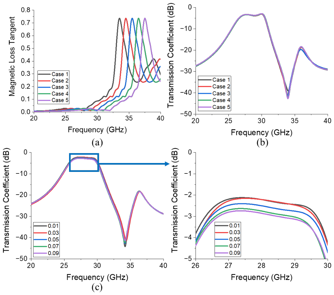
The analysis for determining the electromagnetic characteristics of the ferrite film was carried out in Figure 10. Figure 10b and Figure 10c present the simulated transmission coefficients corresponding to the different magnetic loss tangent cases illustrated in Figure 10a and different dielectric loss tangent (tan δ) values of the ferrite film, respectively.
Figure 10a reveals that even when the magnetic resonance frequency of the ferrite material varies from 28 to 32 GHz, it negligibly impacts both insertion loss and attenuation, as shown in Figure 10b. However, Figure 10c demonstrates that an increase in the dielectric loss tangent noticeably increases insertion loss from 2.21 dB (tan δ = 0.01) to 2.86 dB (tan δ = 0.09), while minimally affecting attenuation. Therefore, minimizing the dielectric loss tangent is essential.
The optimized parameter dimensions obtained from the geometric parametric analysis of the ferrite film are as follows: l = 0.7 mm and h = 0.25 mm, as per Figure 8a. Furthermore, the electromagnetic analysis presented in Figure 10 reveals that the dielectric loss tangent must be maintained as low as possible, and the magnetic loss tangent should begin to increase near 30 GHz to minimize insertion loss.
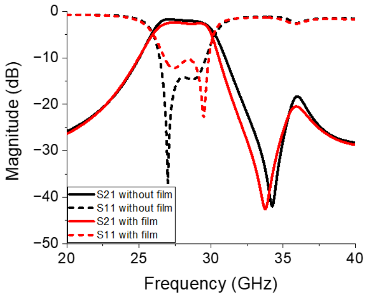
Figure 11 compares the final simulation results obtained from the BPF without and with the integration of the ferrite film. Specifically, the filter with the embedded ferrite film exhibited an insertion loss of 1.59 dB at 28 GHz and an attenuation of 23.58 dB at 32 GHz, whereas the insertion loss and attenuation were 1.02 dB and 18.11 dB, respectively, in the design without ferrite film integration. To isolate the performance of the filtering section, these insertion losses are calculated by subtracting the contribution of the reference transmission line, as depicted in Figure 5. These results validate the effectiveness of the proposed magnetic-resonance-assisted filtering approach in terms of achieving excellent stop-band suppression without increasing the complexity or physical footprint of the circuit. The upper stop-band attenuation of the ferrite-integrated BPF improved considerably while maintaining acceptable insertion loss within the pass-band in relation to that obtained using the SRR-only design.

3. Fabrication and Measurement

3.1. Fabrication

3.1.1. Fabrication of the BPF

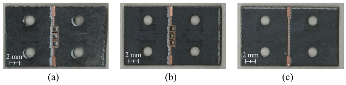
The Rogers RT/duroid 5880 substrate(Chandler, AZ, USA) was used to fabricate the proposed BPF. Moreover, the chemical etching process used to prepare conventional printed-circuit boards (PCBs) proved unsuitable for fabricating small features such as the cavity holes with dimensions of 0.7 mm × 0.7 mm. Therefore, a laser etching process developed by LPKF Laser & Electronics for high-precision PCB fabrication was employed. The fabricated BPF is displayed in Figure 12.

3.1.2. Fabrication of the Ferrite Film

The Ba-W ferrite was synthesized using the optimized composition (BaNi1.9Co0.1Fe16O27) via a molten-salt-assisted sol–gel method. Briefly, stoichiometric amounts of Ba2+, Ni2+, Co2+, and Fe3+ precursors were dissolved in an aqueous solution, to which citric acid was added to initiate the sol–gel reaction. The dried gel powder was subsequently ground and mixed with 50 wt% NaCl, which was the molten-salt medium, followed by calcination at 1250 °C for 3 h. After calcination, any residual NaCl was removed by washing three times with deionized water, yielding single-phase Ba-W hexaferrite powders.
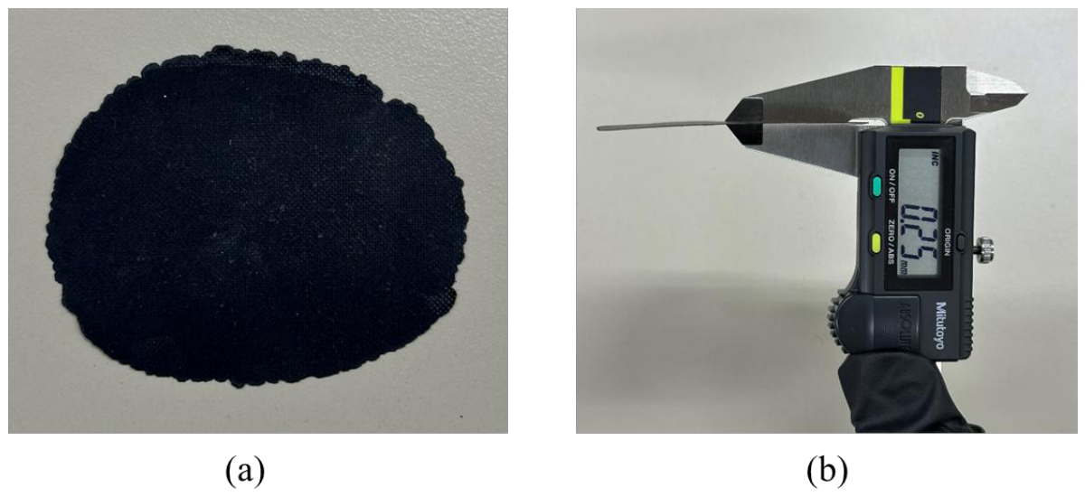
To fabricate the Ba-W hexaferrite films, the synthesized Ni–Co-substituted Ba-W hexaferrite powders were mixed with a thermoplastic polyurethane (TPU) solution at a weight ratio of 3:7, and the mixture was homogenized using a planetary paste mixer (ARE-310, THINKY, Tokyo, Japan) at 2000 rpm for 3 min, followed by defoaming at 2200 rpm for 2 min. The resulting mixed paste was dried in an oven at 130 °C for 24 h. Finally, the dried mixture was hot-pressed using a high-temperature hydraulic press at 150 °C for 1 h under a uniaxial pressure of 40 tons with a 0.25 mm spacer, yielding a W-type hexaferrite–TPU composite film with the target thickness. The detailed synthesis and film fabrication procedure are reported in our previous work [47]. The fabricated hexaferrite film is presented in Figure 13a, and the thickness of the film, measured using a vernier caliper, is confirmed to be 0.25 mm (Figure 13b).
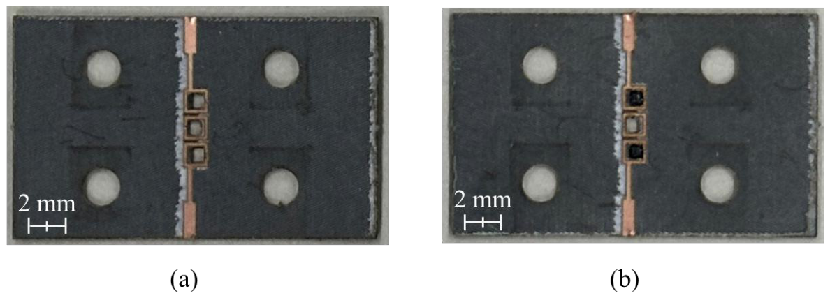
Ferrite films with dimensions of 0.7 mm × 0.7 mm are fabricated using a laser cutting machine (C30, Coryart, Seoul, Republic of Korea) and subsequently embedded in the air cavities, as illustrated in Figure 14b.

3.2. Measurement Results

3.2.1. Measurement of W-Type Hexaferrite Film

The complex permittivity and permeability values of the ferrite films were measured using a vector network analyzer (N5291A, Keysight, Santa Rosa, CA, USA) via a waveguide and free space measurement system (FS-110, EMLabs, Kobe, Japan) in the K- (18–26.5 GHz) and Ka-band (26.5–40 GHz) frequency ranges. The measurements conducted in the K-band employed a waveguide system, and Keysight K11644A (Santa Rosa, CA, USA) mechanical waveguide calibration kits were used for calibration in each band. The measurements in the Ka-band were conducted using a free-space measurement system, with TRL (thru-reflet-line) calibration conducted by following the protocol provided by the manufacturer.
The measured complex permittivity, dielectric loss tangent, complex permeability, and magnetic loss tangent are presented in Figure 15. The real part of the permittivity remained nearly constant at ~6.2, and the imaginary part was ~0.2 within the measured frequency range, corresponding to a dielectric loss tangent of ~0.03 with minimal variation across this frequency range. In contrast, the complex permeability increased sharply above 30 GHz owing to FMR, reaching a maximum at ~35.5 GHz, at which the peak magnetic loss tangent was 0.736. Compared to the virtual material parameters used in the earlier simulations, the fabricated ferrite films yielded consistently lower dielectric losses across the entire frequency band while exhibiting higher magnetic losses in the upper stop-band.
Furthermore, the onset frequency and spectral profile of the measured permeability closely matched the virtual model, validating the correlation between the FMR frequency and the Co substitution content used in the compositional design. These results confirm that fine-tuning the Co content allows the resonance frequency of the W-type hexaferrite to be precisely controlled.

3.2.2. Measurement of BPF with the Hexaferrite Film

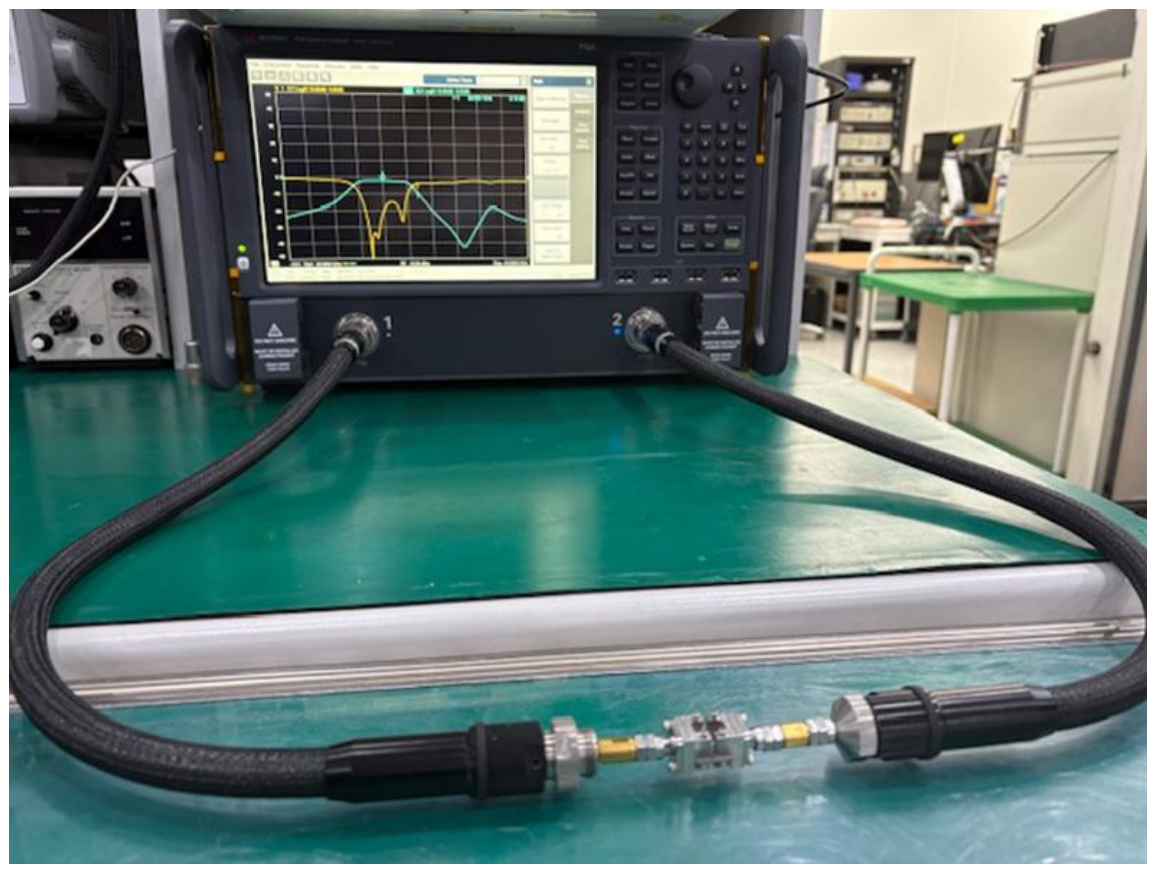
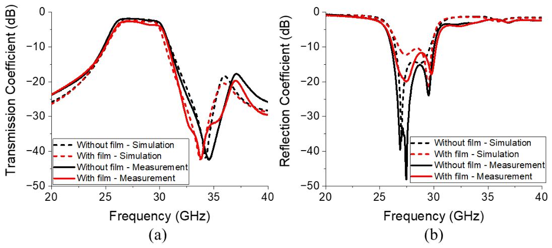
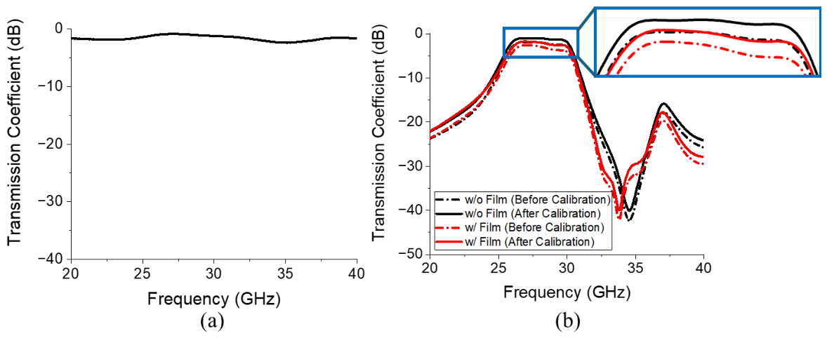
As illustrated in Figure 16, the S-parameters of the proposed BPF were measured using a performance network analyzer (N5227B, Keysight, Santa Rosa, CA, USA). A full two-port calibration was conducted based on the SOLT (short circuit, open circuit, load, and thru) method using a calibration kit (N4694-60001, Keysight, Santa Rosa, CA, USA) Figure 17 compares the simulated and measured S-parameters of the proposed filter. Specifically, Figure 17a and Figure 17b display the transmission and reflection coefficients, respectively. Figure 17a reveals that the filter with the embedded ferrite film exhibited an insertion loss of 1.95 dB at 28 GHz and an attenuation of 24.45 dB at 32 GHz, whereas the design without ferrite film integration exhibited an insertion loss of 1.01 dB and attenuation of 20.04 dB. These results are obtained after subtracting the insertion loss of 0.93 dB measured at 28 GHz from the reference transmission line, as shown in Figure 18a, and Figure 18b compares the results obtained before and after calibration.
Integrating the ferrite film into the BPF improved attenuation performance by 22%, while maintaining acceptable insertion loss within the pass-band. Table 1 compares the measured and simulated results obtained from the proposed BPF. By comparing the performance before and after the insertion of the magnetic film, a substantial improvement in the upper stop-band attenuation is clearly observed. Specifically, at the target frequency of 32 GHz, the attenuation is enhanced by 5.47 dB in the simulation and 4.41 dB in the measurement. These results quantitatively demonstrate that the W-type hexaferrite film successfully induces tailored magnetic resonance to suppress undesired signals in the upper stop-band while maintaining the pass-band characteristics.
To compare the performance of the proposed filter, a comparison with recent millimeter-wave bandpass filters is summarized in Table 2. Conventional technologies such as LTCC [16], TGV [27], MEMS [29], and multilayer PCB [34] provide high stop-band attenuation. However, they generally suffer from high fabrication complexity and cost due to the requirement of 3D multilayer stacking, intricate glass etching, or sophisticated surface micromachining processes. In contrast, the proposed filter introduces a material-based suppression method utilizing the FMR of the W-type hexaferrite film. This approach achieves a competitive upper stop-band attenuation of 24.45 dB at 32 GHz with a simple planar structure, demonstrating significant advantages in terms of cost-effectiveness, fabrication simplicity, and overall miniaturization.

4. Discussion

In this work, a novel approach was proposed for enhancing upper stop-band attenuation in a millimeter-wave BPF, and this method was demonstrated by integrating a W-type hexaferrite film into an SRR-based filter architecture. The proposed method exploits the FMR characteristics of the ferrite material, which were deliberately engineered to exhibit an increasing magnetic loss tangent near 30 GHz while maintaining a low dielectric loss tangent to minimize insertion loss.
Parametric electromagnetic simulations and field-distribution analysis revealed the optimal locations for inserting the ferrite film and forming an air cavity within the SRR structure. A compact square-shaped ferrite film (0.7 mm × 0.7 mm × 0.25 mm) was fabricated and integrated into the regions containing a concentrated magnetic field, while an air cavity was introduced into the region containing a strong electric field to mitigate bandwidth degradation.
Both simulation and measurement results validated the effectiveness of the proposed design strategy. The attenuation offered by the fabricated BPF with the integrated ferrite film improved to 24.45 dB at 32 GHz, representing a 22% enhancement over that offered by the SRR-only design, while maintaining an acceptable insertion loss of 1.95 dB at 28 GHz after calibration. These results confirm that magnetic-resonance-assisted filtering using hexaferrite films can serve as a viable and compact solution for tailored stop-band suppression in millimeter-wave BPFs without increasing circuit complexity and size. The proposed design offers a promising pathway for developing advanced filtering solutions applicable to future 5G and high-frequency communication systems.

Author Contributions

Conceptualization, E.P. and S.L.; methodology, H.K., H.L. and E.P.; software, H.K.; validation, H.L., E.P. and S.-H.H.; formal analysis, H.K., H.L. and E.P.; investigation, H.K., E.P., S.-H.H. and S.-B.L.; data curation, H.K., H.L., K.K. and Y.K.; writing—original draft preparation, H.K. and H.L.; writing—review and editing, H.K., H.L., K.K. and Y.K.; visualization, H.K., H.L. and K.K.; supervision, S.-B.L. and S.L.; project administration, S.L.; funding acquisition, S.L. All authors have read and agreed to the published version of the manuscript.

Funding

This research was supported by the National Research Foundation of Korea (NRF) grant funded by the Korean government (MSIT) (2020M3H4A3081832) and Chung-Ang University Research Scholarship Grants in 2026.

Institutional Review Board Statement

Not applicable.

Informed Consent Statement

Not applicable.

Data Availability Statement

The data presented in this study are available on request from the corresponding author.

Conflicts of Interest

The authors declare no conflicts of interest.

References

  1. He, X.; Ding, D.; Zhang, X.Y. An SIW-based wideband 5G mmWave bandpass filter by using multimode resonator. IEEE Microw. Wirel. Technol. Lett. 2025, 35, 412–415. [Google Scholar] [CrossRef] [Scilit]
  2. Chen, Q.; Cheng, Y.F.; Peng, Q.H.; Liao, C. A Wideband and Compact Millimeter-Wave Antenna Array Fed by Printed Ridge Gap Waveguide for 5G Applications. J. Electromagn. Eng. Sci. 2024, 24, 485–493. [Google Scholar] [CrossRef] [Scilit]
  3. Nam, K.H.; Hong, N.P.; Park, J.S. A Novel Direct-Binary Amplitude Modulator Integrated with a 16-Times Frequency Multiplier for 5G+ Applications. J. Electromagn. Eng. Sci. 2024, 24, 556–564. [Google Scholar] [CrossRef] [Scilit]
  4. Nesser, H.; Grisolia, J.; Alnasser, T.; Viallet, B.; Ressier, L. Towards wireless highly sensitive capacitive strain sensors based on gold colloidal nanoparticles. Nanoscale 2018, 10, 10479–10487. [Google Scholar] [CrossRef] [Scilit] [PubMed]
  5. Rajagopalan, H.; Rahmat-Samii, Y. Dielectric and conductor loss quantification for microstrip reflectarray: Simulations and measurements. IEEE Trans. Antennas Propag. 2008, 56, 1192–1196. [Google Scholar] [CrossRef] [Scilit]
  6. Fischer, B.E.; Lahaie, I.J.; Huang, M.D.; Herben, M.H.A.J.; Reniers, A.C.F.; Smulders, P.F.M. Causes of discrepancies between measurements and EM simulations of millimeter-wave antennas. IEEE Antennas Propag. Mag. 2013, 55, 139–149. [Google Scholar] [CrossRef] [Scilit]
  7. Shen, G.; Che, W.; Feng, W.; Shi, Y.; Shen, Y. Low insertion-loss MMIC bandpass filter using lumped-distributed parameters for 5G millimeter-wave application. IEEE Trans. Compon. Packag. Manuf. Technol. 2021, 11, 98–108. [Google Scholar] [CrossRef] [Scilit]
  8. Ali, M.; Liu, F.; Watanabe, A.; Raj, P.M.; Sundaram, V.; Tentzeris, M.M.; Tummala, R.R. First demonstration of compact, ultra-thin low-pass and bandpass filters for 5G small-cell applications. IEEE Microw. Wirel. Compon. Lett. 2018, 28, 1110–1112. [Google Scholar] [CrossRef] [Scilit]
  9. Shi, Y.; Feng, W.; Wang, H.; Zheng, S.; Zhou, M.; Wu, Q. Compact planar W-band front-end module based on EBG packaging and LTCC circuits. IEEE Trans. Circuits Syst. II Express Briefs 2021, 68, 878–882. [Google Scholar] [CrossRef] [Scilit]
  10. Lee, J.H.; Pinel, S.; Laskar, J.; Tentzeris, M.M. Design and development of advanced cavity-based dual-mode filters using low-temperature co-fired ceramic technology for V-band gigabit wireless systems. IEEE Trans. Microw. Theory Tech. 2007, 55, 1869–1878. [Google Scholar] [CrossRef]
  11. Rigaudeau, L.; Ferrand, P.; Baillargeat, D.; Bila, S.; Verdeyme, S.; Lahti, M.; Jaakola, T. LTCC 3-D resonators applied to the design of very compact filters for Q-band applications. IEEE Trans. Microw. Theory Tech. 2006, 54, 2620–2626. [Google Scholar] [CrossRef] [Scilit]
  12. Lee, J.H.; DeJean, G.; Sarkar, S.; Pinel, S.; Lim, K.; Papapolymerou, J.; Laskar, J.; Tentzeris, M.M. Highly integrated millimeter-wave passive components using 3-D LTCC system-on-package (SOP) technology. IEEE Trans. Microw. Theory Tech. 2005, 53, 2220–2228. [Google Scholar]
  13. Choi, B.G.; Stubbs, M.G.; Park, C.S. A Ka-band narrow bandpass filter using LTCC technology. IEEE Microw. Wirel. Compon. Lett. 2003, 13, 388–389. [Google Scholar] [CrossRef] [Scilit]
  14. Shen, G.; Che, W.; Feng, W.; Shi, Y.; Xu, F.; Xue, Q. Ultra-low-loss millimeter-wave LTCC bandpass filters based on flexible design of lumped and distributed circuits. IEEE Trans. Circuits Syst. II Express Briefs 2021, 68, 1123–1127. [Google Scholar] [CrossRef] [Scilit]
  15. Shen, G.; Che, W.; Xue, Q. Compact microwave and millimeter-wave bandpass filters using LTCC-based hybrid lumped and distributed resonators. IEEE Access 2019, 7, 104797–104809. [Google Scholar] [CrossRef] [Scilit]
  16. Huang, X.; Zhang, X.; Zhou, L.; Xu, J.X.; Mao, J.F. Low-loss self-packaged Ka-band LTCC filter using artificial multimode SIW resonator. IEEE Trans. Circuits Syst. II Express Briefs 2023, 70, 451–455. [Google Scholar] [CrossRef] [Scilit]
  17. Chakraborty, S.; Yang, Y.; Zhu, X.; Sevimli, O.; Xue, Q.; Esselle, K.; Heimlich, M. A Broadside-Coupled Meander-Line Resonator in 0.13-μm SiGe Technology for Millimeter-Wave Application. IEEE Electron Device Lett. 2016, 37, 329–332. [Google Scholar] [CrossRef] [Scilit]
  18. Kim, D.M.; Min, B.W.; Yook, J.M. Compact mm-wave bandpass filters using silicon integrated passive device technology. IEEE Microw. Wirel. Compon. Lett. 2019, 29, 638–640. [Google Scholar] [CrossRef] [Scilit]
  19. Sun, F.; Zhu, H.; Zhu, X.; Yang, Y.; Gomez-Garcia, R. Design of On-Chip Millimeter-Wave Bandpass Filters Using Multilayer Patterned-Ground Element in 0.13-μm (Bi)-CMOS Technology. IEEE Trans. Microw. Theory Tech. 2019, 67, 5159–5170. [Google Scholar] [CrossRef] [Scilit]
  20. Zhu, H.; Yang, Y.; Zhu, X.; Sun, Y.; Wong, S.W. Miniaturized resonator and bandpass filter for silicon-based monolithic microwave and millimeter-wave integrated circuits. IEEE Trans. Circuits Syst. I Regul. Pap. 2018, 65, 4062–4071. [Google Scholar] [CrossRef] [Scilit]
  21. Yang, Y.; Zhu, X.; Dutkiewicz, E.; Xue, Q. Design of a miniaturized on-chip bandpass filter using edge-coupled resonators for millimeter-wave applications. IEEE Trans. Electron Devices 2017, 64, 3822–3828. [Google Scholar] [CrossRef] [Scilit]
  22. Diedhiou, D.L.; Rius, E.; Favennec, J.F.; El Mostrah, A. Ku-band cross-coupled ceramic SIW filter using a novel electric cross-coupling. IEEE Microw. Wirel. Compon. Lett. 2015, 25, 109–111. [Google Scholar] [CrossRef] [Scilit]
  23. Wong, S.W.; Wang, K.; Chen, Z.N.; Chu, Q.X. Design of millimeter-wave bandpass filter using electric coupling of substrate integrated waveguide (SIW). IEEE Microw. Wirel. Compon. Lett. 2014, 24, 26–28. [Google Scholar] [CrossRef] [Scilit]
  24. Hao, Z.C.; Ding, W.Q.; Hong, W. Developing Low-Cost W-Band SIW Bandpass Filters Using the Commercially Available Printed-Circuit-Board Technology. IEEE Trans. Microw. Theory Tech. 2016, 64, 1775–1786. [Google Scholar] [CrossRef] [Scilit]
  25. Zhu, X.C.; Hong, W.; Wu, K.; Tang, H.J.; Hao, Z.C.; Chen, J.X.; Chu, P. Design and implementation of a triple-mode planar filter. IEEE Microw. Wirel. Compon. Lett. 2013, 23, 243–245. [Google Scholar] [CrossRef] [Scilit]
  26. Mira, F.; Mateu, J.; Cogollos, S.; Boria, V.E. Design of ultra-wideband substrate integrated waveguide (SIW) filters in zigzag topology. IEEE Microw. Wirel. Compon. Lett. 2009, 19, 281–283. [Google Scholar] [CrossRef] [Scilit]
  27. Wang, L.; Chen, H.; Li, W.; Zhang, J.; Gao, L.; Cai, X.; Fang, Z.; Li, Y.; Zhu, Y.; Zhang, R. A 28-GHz compact substrate-integrated waveguide bandpass filter with defected ground structure using TGV technology. IEEE Trans. Compon. Packag. Manuf. Technol. 2023, 13, 2008–2015. [Google Scholar] [CrossRef] [Scilit]
  28. Zhang, Q.; Zhao, B.; Hu, S.; Tian, R.; Li, C.; Fang, L.; Zhang, Y.; Liu, Y.; Zhao, J.; Gan, X. A waveguide-integrated self-powered van der Waals heterostructure photodetector with high performance at the telecom wavelength. Nanoscale 2023, 15, 15761–15767. [Google Scholar] [CrossRef] [Scilit]
  29. Dey, S.; Koul, S.K. Reliable, compact, and tunable MEMS bandpass filter using arrays of series and shunt bridges for 28-GHz 5G applications. IEEE Trans. Microw. Theory Tech. 2021, 69, 75–88. [Google Scholar] [CrossRef] [Scilit]
  30. Kim, H.T.; Park, J.H.; Kim, Y.K.; Kwon, Y. Low-loss and compact V-band MEMS-based analog tunable bandpass filters. IEEE Microw. Wirel. Compon. Lett. 2002, 12, 432–434. [Google Scholar]
  31. Stickel, M.; Kremer, P.; Eleftheriades, G.V. A millimeter-wave bandpass waveguide filter using a width-stacked silicon bulk micromachining approach. IEEE Microw. Wirel. Compon. Lett. 2006, 16, 209–211. [Google Scholar] [CrossRef] [Scilit]
  32. Blondy, P.; Brown, A.R.; Gros, D.; Rebeiz, G.M. Low-loss micromachined filters for millimeter-wave communication systems. IEEE Trans. Microw. Theory Tech. 1998, 46, 2283–2288. [Google Scholar] [CrossRef] [Scilit]
  33. Lucyszyn, S.; Miyaguchi, K.; Jiang, H.W.; Robertson, I.D.; Fisher, G.; Lord, A.; Choi, J.Y. Micromachined RF-coupled cantilever inverted-microstrip millimeter-wave filters. J. Microelectromech. Syst. 2008, 17, 767–776. [Google Scholar] [CrossRef] [Scilit]
  34. Rao, Y.; Qian, H.J.; Zhou, J.; Dong, Y.; Luo, X. Miniaturized 28-GHz packaged bandpass filter with high selectivity and wide stopband using multilayer PCB technology. IEEE Microw. Wirel. Compon. Lett. 2022, 32, 664–667. [Google Scholar] [CrossRef] [Scilit]
  35. Qin, W.; Li, Z.; Shi, T.; Sun, W.; Fang, Z. A 1.52-DB-Insertion-Loss, V-Band Coupled Bandpass Filter with a Three-Dimensional Metal Coaxial Structure Using 3D Printing and MEMS Hybrid Technology. In Proceedings of the 2024 IEEE International Symposium on Radio-Frequency Integration Technology (RFIT 2024), Chengdu, China, 28–30 August 2024; Volume 2, pp. 1–3. [Google Scholar]
  36. Leo, A.; Bramanti, A.P.; Giusti, D.; Quaglia, F.; Maruccio, G. Reconfigurable split ring resonators by MEMS-driven geometrical tuning. Sensors 2023, 23, 1382. [Google Scholar] [CrossRef] [Scilit]
  37. Penciu, R.S.; Aydin, K.; Kafesaki, M.; Koschny, T.; Ozbay, E.; Economou, E.N.; Soukoulis, C.M. Multi-gap individual and coupled split-ring resonator structures. Opt. Express 2008, 16, 18131. [Google Scholar] [CrossRef] [Scilit]
  38. Hesmer, F.; Tatartschuk, E.; Zhuromskyy, O.; Radkovskaya, A.A.; Shamonin, M.; Hao, T.; Stevens, C.J.; Faulkner, G.; Edwards, D.J.; Shamonina, E. Coupling mechanisms for split ring resonators: Theory and experiment. Phys. Status Solidi Basic Res. 2007, 244, 1170–1175. [Google Scholar] [CrossRef] [Scilit]
  39. La Spada, L. Metasurfaces for Advanced Sensing and Diagnostics. Sensors 2019, 19, 355. [Google Scholar] [CrossRef] [Scilit]
  40. Zhang, Q.; Wen, X.; Li, G.; Ruan, Q.; Wang, J.; Xiong, Q. Multiple magnetic mode-based Fano resonance in split-ring resonator/disk nanocavities. ACS Nano 2013, 7, 11071–11078. [Google Scholar] [CrossRef] [Scilit]
  41. Kim, N.; In, S.; Lee, D.; Rhie, J.; Jeong, J.; Kim, D.S.; Park, N. Colossal terahertz field enhancement using split-ring resonators with a sub-10 nm gap. ACS Photonics 2018, 5, 278–283. [Google Scholar] [CrossRef] [Scilit]
  42. Du, C.; Zhou, D.; Guo, H.H.; Pang, Y.Q.; Shi, H.Y.; Liu, W.F.; Su, J.Z.; Singh, C.; Trukhanov, S.; Trukhanov, A.; et al. An ultra-broadband terahertz metamaterial coherent absorber using multilayer electric ring resonator structures based on anti-reflection coating. Nanoscale 2020, 12, 9769–9775. [Google Scholar] [CrossRef] [Scilit]
  43. Lee, S.M.; Lee, T.W.; Kang, Y.M. Tunable and broad-band electromagnetic wave absorption using W-type Hexaferrites in 1–40 GHz range. J. Alloys Compd. 2023, 962, 171060. [Google Scholar] [CrossRef] [Scilit]
  44. Imade, Y.; Ulbricht, R.; Tomoda, M.; Matsuda, O.; Seniutinas, G.; Juodkazis, S.; Wright, O.B. Gigahertz optomechanical modulation by split-ring-resonator nanophotonic meta-atom arrays. Nano Lett. 2017, 17, 6684–6689. [Google Scholar] [CrossRef] [Scilit]
  45. Lee, H.; Ryu, S.H.; Kwon, S.J.; Choi, J.R.; Lee, S.B.; Park, B. Absorption-dominant mmWave EMI shielding films with ultralow reflection using ferromagnetic resonance frequency tunable M-type ferrites. Nano-Micro Lett. 2023, 15, 76. [Google Scholar] [CrossRef] [Scilit] [PubMed]
  46. Rai, G.M.; Aen, F.; Misbah-Ul-Islam; Rana, M.U. Dielectric and magnetic behavior of BaCd2−xSrxFe16O27 W-type hexagonal ferrites. J. Alloys Compd. 2011, 509, 4793–4796. [Google Scholar]
  47. Jang, M.; Lee, H.; Jun, S.; Jin, S.; Bok, S.; In, J.; Park, B.J. Broadband electromagnetic wave absorbers with Ni-Co substituted Ba-W hexaferrites synthesized via citric acid-assisted sol-gel reaction. Alloys Compd. 2025, 1039, 183342. [Google Scholar] [CrossRef] [Scilit]
  48. Quan, D.M.; Hung, L.Q. The characteristics of the band-pass filter from the various parameters of the substrate. J. Phys. Conf. Ser. 2020, 1441, 012047. [Google Scholar] [CrossRef] [Scilit]
Figure 1. (a) Perspective view and (b) enlarged top view of the proposed BPF.
Micromachines 17 00534 g001
Figure 2. Equivalent LC circuit.
Micromachines 17 00534 g002
Figure 3. Simulated transmission coefficients obtained by varying the geometric parameters of the BPF illustrated in Figure 1b: (a) g a p 1 (0.1–0.3 mm), (b) l 1 (1.2–1.5 mm), (c) w 3 (0.1–0.25 mm), and (d) g a p 2 (0.1–1.6 mm).
Micromachines 17 00534 g003
Figure 4. (a) Simulation setup of the proposed BPF with a connector and the (b) simulated S-parameters. In (a), the orange and yellow colors represent the Rogers RT/duroid 5880 substrate and copper, respectively, while the grey parts indicate the connectors.
Micromachines 17 00534 g004
Figure 5. (a) Simulation setup of the proposed transmission line with a connector and the (b) simulated transmission coefficient. The color representations in (a) are identical to those in Figure 4.
Micromachines 17 00534 g005
Figure 6. (a) Magnitude of the magnetic-field distribution, (b) electric-field distribution and (c) surface current distributions at 29.9 GHz.
Micromachines 17 00534 g006
Figure 7. (a) Complex permittivity, (b) dielectric loss tangent, (c) complex permeability, and (d) magnetic loss tangent of the ferrite film.
Micromachines 17 00534 g007
Figure 8. (a) Ferrite films inserted into the first and third rings, (b) modified structure with an air cavity formed in the concentrated electric-field region, and (c) side views of the ferrite films inserted into the first and third rings. Simulated transmission coefficients corresponding to the structure shown in (d,e).
Micromachines 17 00534 g008
Figure 9. Simulated transmission coefficients corresponding to variations in the geometrical parameters of the ferrite film illustrated in Figure 8a: (a) l (0.5–0.8 mm) and (b) h (0.22–0.28 mm).
Micromachines 17 00534 g009
Figure 10. (a) Plot of magnetic loss tangent corresponding to different cases with varying magnetic resonance frequencies. (b) Simulated transmission coefficients corresponding to each case shown in (a,c) varying values of dielectric loss tangent.
Micromachines 17 00534 g010
Figure 11. Comparison of the final simulated scattering parameters of the BPF without and with the ferrite film integrated.
Micromachines 17 00534 g011
Figure 12. Fabricated proposed BPF (a) without and (b) with an air cavity and (c) a reference transmission line.
Micromachines 17 00534 g012
Figure 13. (a) Fabricated ferrite film and (b) thickness measurement using a vernier caliper.
Micromachines 17 00534 g013
Figure 14. Fabricated proposed BPF with an air cavity (a) before and (b) after inserting the ferrite films.
Micromachines 17 00534 g014
Figure 15. (a) Complex permittivity, (b) dielectric loss tangent, (c) complex permeability, and (d) magnetic loss tangent of the final ferrite film.
Micromachines 17 00534 g015
Figure 16. Photograph of the measurement setup.
Micromachines 17 00534 g016
Figure 17. Simulated and measured (a) transmission and (b) reflection coefficients of the proposed BPF.
Micromachines 17 00534 g017
Figure 18. Measured transmission coefficients of the (a) reference transmission line and (b) comparison of the results obtained before and after calibration. The blue box indicates the magnified region shown on the right.
Micromachines 17 00534 g018
Table 1. Summary of the simulated and measured results obtained from the proposed BPF.
Insertion Loss
(at 28 GHz)
Attenuation (at 32 GHz)
Simulation resultWithout film1.02 dB18.11 dB
With film1.59 dB23.58 dB
Measurement resultWithout film1.01 dB20.04 dB
With film1.95 dB24.45 dB
Table 2. Performance comparison of the proposed BPF with millimeter-wave filters.
Ref.Technology/Structure f c (a)
(GHz)
Upper Stop-Band Attenuation (dB)Fabrication
Complexity (c)
Suppression Method
[16]LTCC/Quad-mode SIW28N/A (b)ComplexArtificial multi-mode cavity
[27]TGV/HMSIW-DGS28.3>20ComplexDefected ground structure (DGS)
[29]MEMS/Series & Shunt Bridges28N/AComplexTunable electrostatic actuation
[34]Multilayer PCB/Stacked SIR28>24MediumCross-coupling & Harmonic suppression
This workPCB/SRR2824.45SimpleFerromagnetic resonance
(a) Center frequency. (b) N/A: the measured results are not provided in the reference. (c) Design complexity: complex (including 3D multilayer/intricate glass etching/sophisticated surface), medium (including standard multi-layer PCB stacking/conventional blind/basic mechanical packaging), and simple (including standard single layer-PCB fabrication/simple planar patterning/simple material attachment).
Disclaimer/Publisher’s Note: The statements, opinions and data contained in all publications are solely those of the individual author(s) and contributor(s) and not of MDPI and/or the editor(s). MDPI and/or the editor(s) disclaim responsibility for any injury to people or property resulting from any ideas, methods, instructions or products referred to in the content.