1. Introduction
Rapid and reliable identification of foodborne pathogens is fundamental to outbreak prevention, source tracing, and routine hazard screening in modern food-supply chains [
1,
2]. In many practical settings—such as production-line inspection, market surveillance, and port-of-entry screening—decision-making is time-critical and therefore requires field-deployable tools that can provide results with minimal delay and operational complexity [
3,
4]. Among high-risk targets, enterohemorrhagic
Escherichia coli O157:H7 (
E. coli O157:H7) is of particular concern because it can initiate severe disease at extremely low infectious doses and is associated with life-threatening complications, including haemolytic uremic syndrome, through Shiga-toxin-mediated vascular injury [
5,
6,
7]. Accordingly,
E. coli O157:H7 has been designated a key control organism in food safety monitoring frameworks.
A variety of on-site detection platforms have been developed to address this need, each with distinct advantages and limitations. Optical techniques such as fluorescence, surface plasmon resonance (SPR), and localized SPR provide high sensitivity and real-time monitoring, but typically rely on bulky optics, precise alignment, and are particularly susceptible to interference from complex sample matrices like food, which challenges their robustness and true portability for field use [
8]. Isothermal nucleic-acid amplification methods, notably loop-mediated isothermal amplification (LAMP), deliver excellent sensitivity and specificity by amplifying target DNA/RNA [
9]; however, they involve complex sample preprocessing (e.g., cell lysis, nucleic-acid extraction) and are susceptible to aerosol contamination, making them less suited for rapid, minimally processed sample analysis in resource-limited settings. Even sophisticated research tools like electro-photonic traps for single-bacterium analysis exist [
10], but their complexity and cost render them impractical for routine field detection.
Field-effect transistor (FET) biosensors translate biochemical recognition at a solid–liquid interface into an electrical signal by modulating the effective gate potential and, consequently, the channel conductance. This transduction principle supports label-free and real-time readout while retaining the intrinsic advantages of semiconductor devices, including miniaturization, low sample-volume operation, and straightforward integration with electronics, which has motivated extensive use in clinical diagnostics, environmental monitoring, and food-safety screening [
11,
12,
13,
14,
15,
16,
17]. However, many FET-based platforms—including those incorporating nanomaterials such as graphene FETs, carbon nanotube (CNT) FETs, and conventional ion-sensitive FETs (ISFETs)—still face practical challenges related to fabrication reproducibility, long-term stability in complex matrices, and integration into compact, low-power readout systems [
18,
19,
20]. Within this family, the extended-gate FET (EG-FET) is particularly attractive for liquid-phase assays because the sensing interface is physically separated from the transistor core: the extended gate can be independently functionalized with biorecognition layers, offers a larger and more flexible surface for surface chemistry, and reduces direct exposure of the transistor to the electrolyte environment, thereby improving operational robustness and device longevity in practical measurements [
21,
22]. Accordingly, sensitivity and interface stability have been widely optimized through materials and surface engineering (e.g., carbon nanotubes and graphene coatings) to enhance charge-coupling efficiency and interfacial signal transduction [
23,
24,
25,
26,
27]. Furthermore, this “sensing-readout” separation design provides EG-FET systems with distinct practical features: (1) Low cost—disposable extended gates and commercial FETs can be used, significantly reducing consumable and manufacturing expenses; (2) Easy deployment—compatibility with portable electronics is achieved by optimizing operating modes (e.g., constant-charge OCP mode), eliminating reliance on bulky instruments; (3) Simple sample preparation—well-designed interfacial chemistry enables direct analysis of complex biological samples such as whole blood, saliva, and urine; (4) Fast response—real-time, continuous signal monitoring meets the demand for rapid on-site detection [
22]. Therefore, developing integrated EG-FET systems represents a promising pathway toward truly field-ready, practical biosensing platforms.
However, progress at the sensing-element level has not yet translated into equally mature, field-deployable instrumentation. In most reported EG-FET demonstrations, biasing, low-noise current readout, and data processing still rely on bulky benchtop equipment (e.g., semiconductor parameter analyzers, precision source meters, and electrochemical workstations), which undermines portability, increases operational cost, and constrains deployment in decentralized testing scenarios. What remains comparatively underdeveloped is a system-level solution that treats the sensor, analog front-end, embedded acquisition/processing, and user-facing software as a single validated chain, with performance verified in an end-to-end manner under biosensing conditions.
In this work, we develop a compact EG-FET integrated sensing system that combines (i) a self-developed EG-FET sensor array with an antibody-functionalized extended gate for specific capture of E. coli O157:H7, (ii) a microcontroller-based acquisition and processing unit enabling real-time signal conditioning and data transmission, and (iii) a host-side visualization interface for data display and basic analysis. As a representative use case, we construct an EG-FET immunosensing interface by covalently immobilizing monoclonal antibodies specific to E. coli O157:H7 on the extended-gate surface, enabling selective bacterial capture and a concentration-dependent electrical response. This end-to-end prototype reduces reliance on benchtop instrumentation and provides a practical engineering pathway toward deployable foodborne-pathogen sensing; moreover, the architecture is readily extensible by substituting the recognition layer to target other pathogens (e.g., Salmonella, Listeria) or food-safety biomarkers (e.g., mycotoxins and antibiotic residues).
2. Materials and Methods
2.1. Materials and Chemicals
The principal electronic components used to construct the EG-FET integrated sensing system included an n-channel MOSFET (UN600N23TE, UN Semiconductor, Shenzhen, China), a microcontroller unit (MCU, GD32F103C8T6, GigaDevice, Beijing, China), precision operational amplifiers (LTC2051HV, Analog Devices, Wilmington, MA, USA), a USB-to-UART interface (PL2303, Prolific Technology, Shenzhen, China), low-dropout linear regulators (AMS1117, Advanced Monolithic Systems, Livermore, CA, USA), a 3.0 V voltage reference (REF3030, Texas Instruments, Dallas, TX, USA), and screen-printed gold electrodes (G210, Changsha Sanjun Electronic Technology Co., Ltd., Changsha, China).
All chemical and biological reagents were of analytical grade and used as received unless otherwise stated. 3-Mercaptopropionic acid (MPA; M103036, Aladdin, Shanghai, China), 1-ethyl-3-(3-dimethylaminopropyl) carbodiimide hydrochloride (EDC; E106172, Aladdin, Shanghai, China), and N-hydroxysuccinimide (NHS; H109330, Aladdin) were used for surface functionalization. Phosphate-buffered saline (PBS, pH 7.4, C10010500BT, Thermo Scientific, Waltham, MA, USA) served as the working buffer. E. coli O157:H7 monoclonal antibody (EC-mab-01, Shanghai Prajna Biology Technique, Shanghai, China) was employed as the biorecognition element, and bovine serum albumin (BSA, BS114, Hefei, China) was used for blocking nonspecific adsorption. A potassium ferricyanide/ferrocyanide redox probe solution (5 mM) was prepared for electrochemical characterization. Ultrapure water was used throughout. The E. coli O157:H7 bacterial stock was maintained and preserved in-house.
2.2. System Architecture of the EG-FET Integrated Sensing System
2.2.1. Sensing Principle of the EG-FET
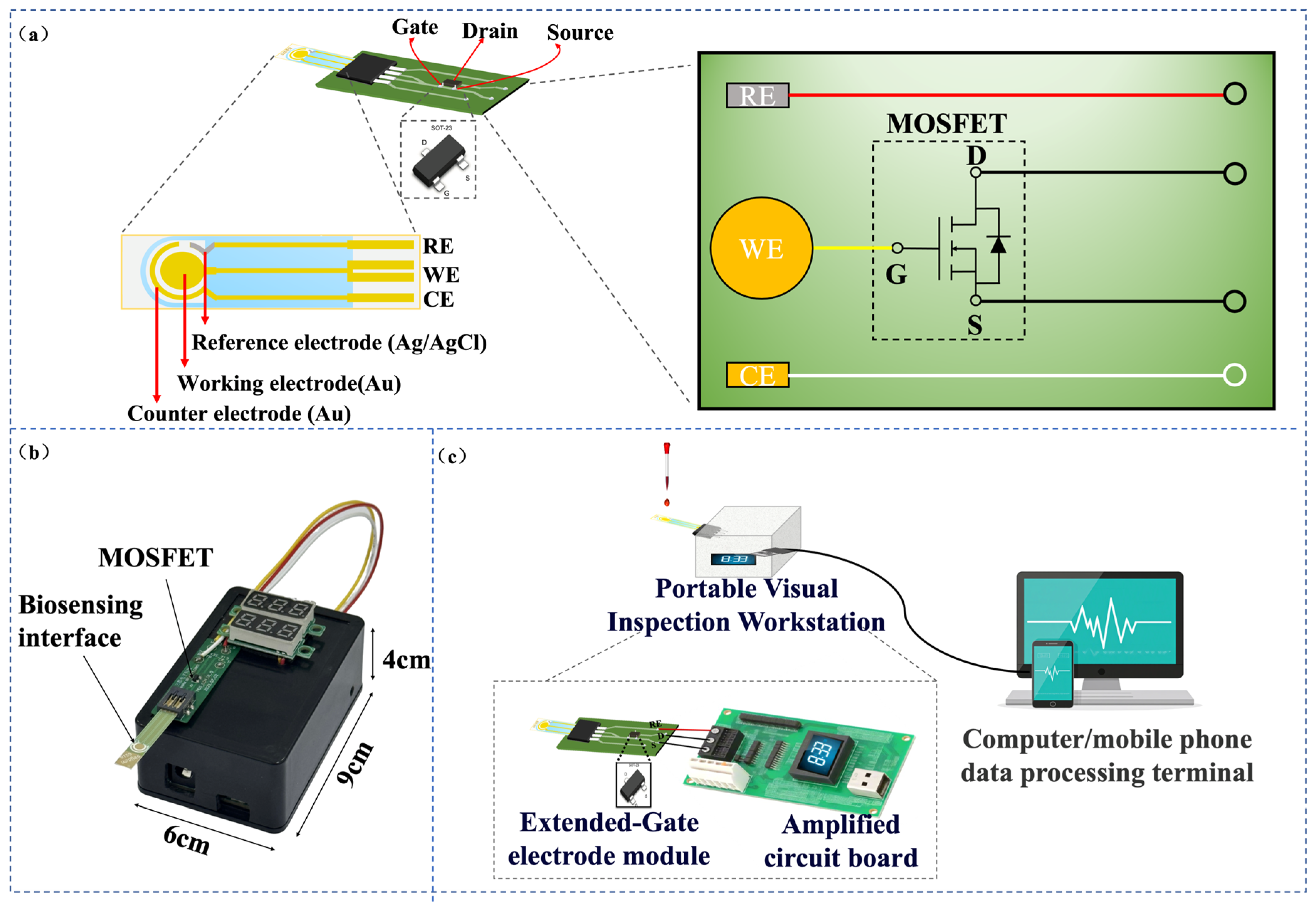
The EG-FET separates the sensing interface from the transistor core. The extended gate is functionalized with biorecognition elements (e.g., antibodies) and contacts the electrolyte during measurement. Binding of the target at the gate/solution interface perturbs the interfacial charge distribution and surface potential, producing an effective gate-voltage shift (ΔVGS), which is capacitively coupled to the MOSFET gate through the conductive connection, modulating channel conduction. This perturbation is capacitively coupled to the MOSFET gate through the conductive connection, modulating channel conduction. The biochemical recognition event is therefore converted into an electrical readout, typically recorded as a change in drain–source current (IDS) at fixed bias or as an equivalent shift in the apparent threshold condition.
2.2.2. Overall System Design
The EG-FET integrated sensing system is implemented as an end-to-end chain comprising a sensor module, an analog front-end for biasing and low-noise current readout, an MCU-based acquisition/communication unit, and host-side software for visualization and data management. The analog front-end converts the weak sensor current into a voltage signal and conditions it for digitization. The MCU (GD32F103C8T6, GigaDevice, Beijing, China) coordinates sampling, performs basic digital processing, and transmits data via a UART link. A host computer interface receives and parses the data stream, displays real-time traces, and stores measurement records for subsequent analysis. Power delivery and voltage referencing are integrated to support stable operation of both analog and digital blocks.
2.3. Hardware Design
2.3.1. Current Sampling and Signal Conditioning Module
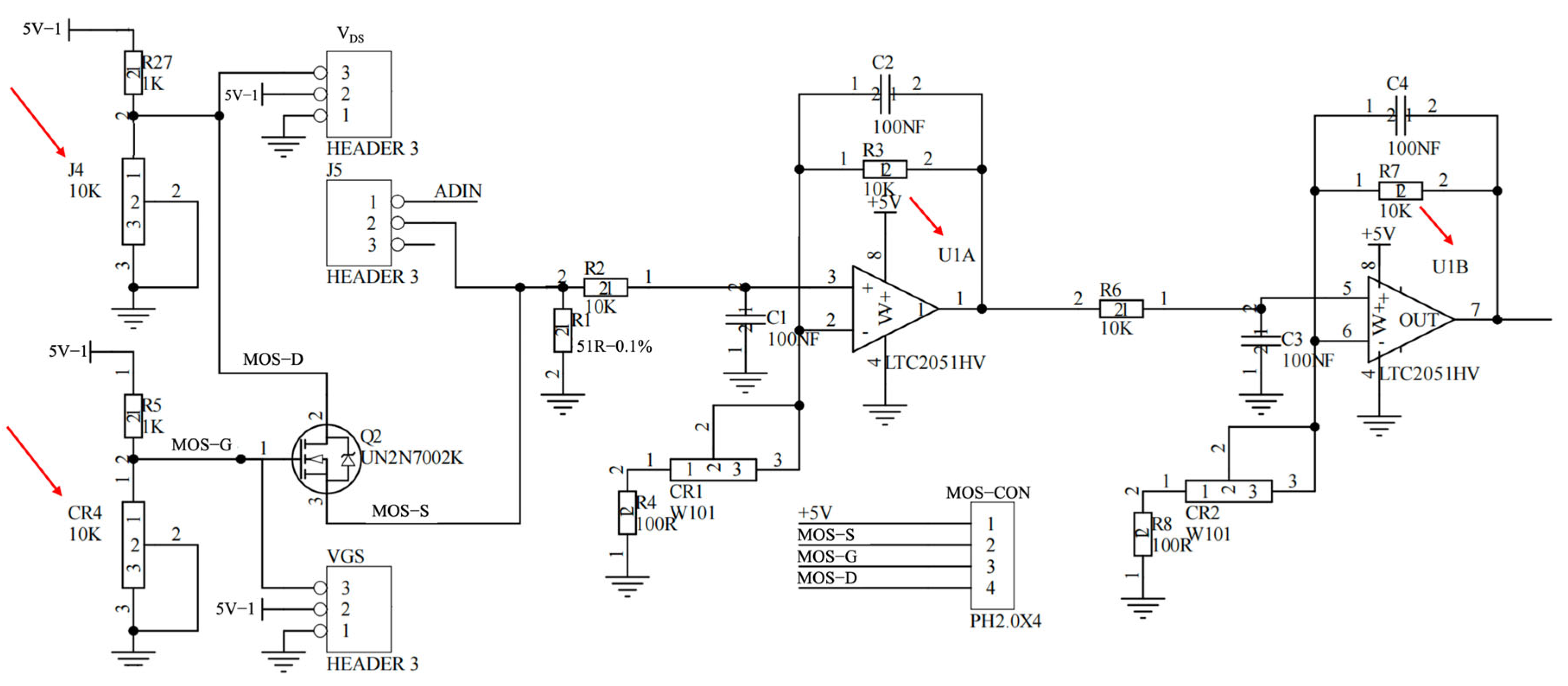
Weak-current readout from the EG-FET is implemented using a low-noise transimpedance stage based on a precision operational amplifier (LTC2051HV, Analog Devices, Wilmington, MA, USA). The drain–source current is converted into a proportional voltage through a feedback network, followed by bandwidth-limiting (RC filtering) to suppress high-frequency noise and improve measurement stability. The conditioned analog signal is routed to the MCU’s ADC for digitization. Component selection and filtering are designed to balance current sensitivity, dynamic range, and response time.
2.3.2. Power Supply Module
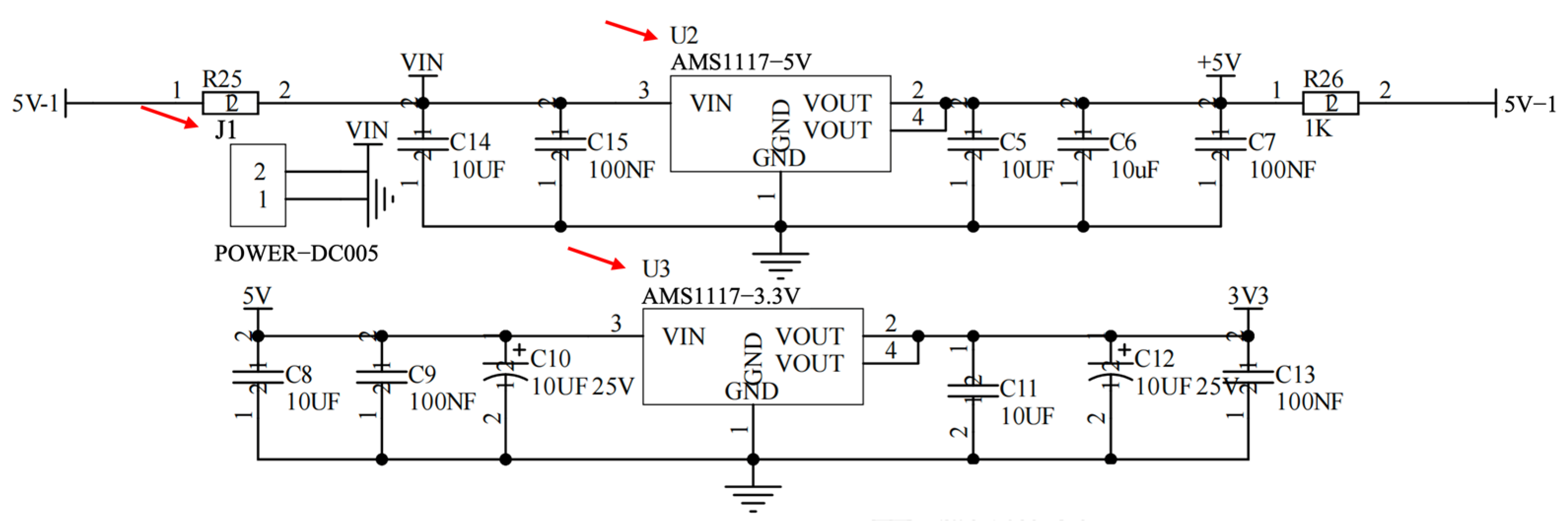
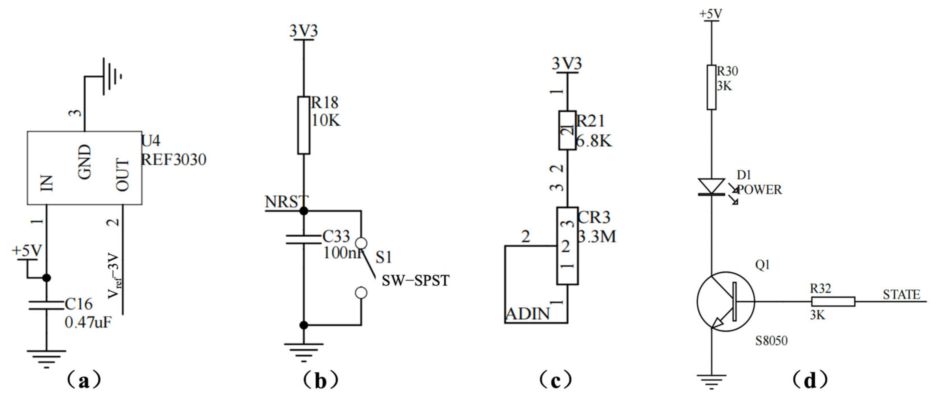
The system supports regulated on-board power for mixed-signal operation. External input power is converted to the required rails using low-dropout regulators (AMS1117, Advanced Monolithic Systems, Livermore, CA, USA), with local decoupling and filtering applied near the analog front-end and the digital core to reduce supply ripple coupling into the measurement path. A dedicated reference source (REF3030, Texas Instruments, Dallas, TX, USA) provides a stable voltage reference for ADC-related measurements and bias stability where applicable.
2.3.3. MCU Module
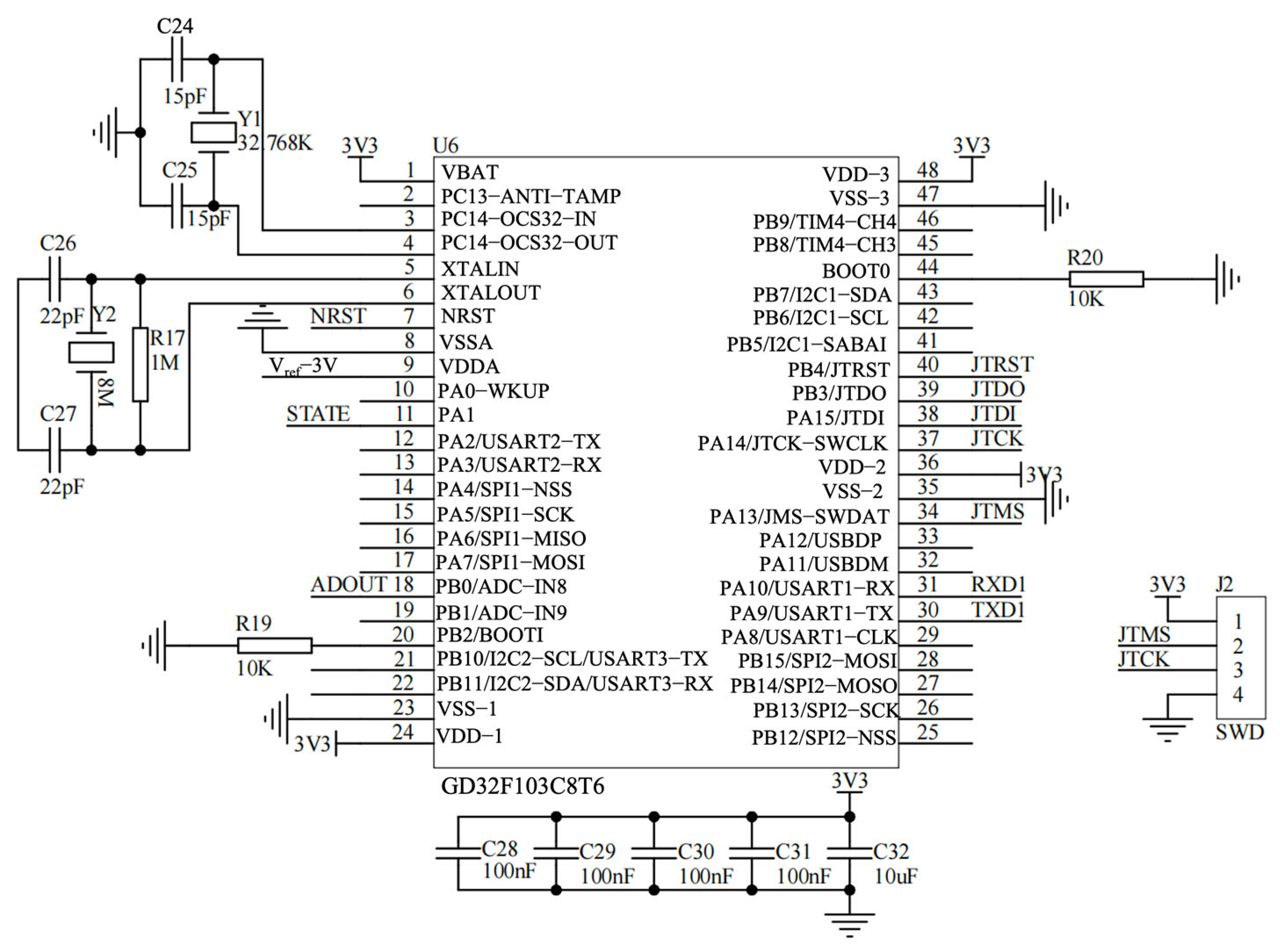
The MCU (GD32F103C8T6, GigaDevice, Beijing, China) serves as the central controller. It manages sampling timing, ADC acquisition, basic data processing, and communication. Standard peripheral interfaces (UART, SPI, and I2C as required) support connectivity to external modules and system expansion. The firmware also handles system initialization and fault recovery through reset/monitoring circuitry.
2.3.4. USB-to-Serial Communication Module
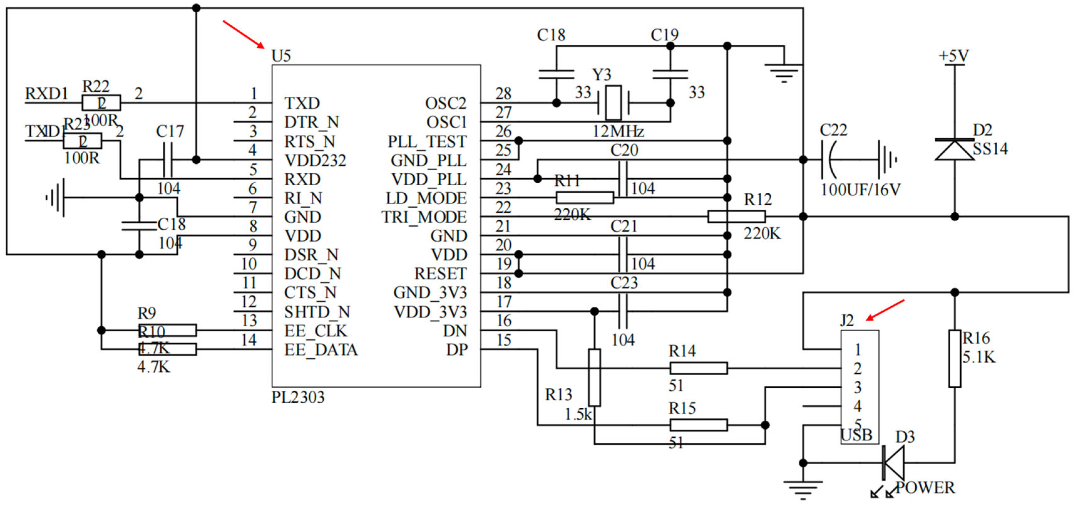
Data transfer to the host computer is implemented using a USB-to-UART bridge (PL2303, Prolific Technology, Shenzhen, China). This module provides a reliable physical and protocol interface for real-time streaming of sampled data and for instrument configuration during testing and debugging.
2.3.5. Auxiliary Modules
To improve measurement robustness and usability, the system includes supporting circuits such as a precision voltage reference, power/reset supervision, and status indicators. Where required, a signal-injection/simulation path is provided for channel verification and calibration during development. These modules ensure repeatable operation and facilitate troubleshooting without altering the sensing interface.
2.4. Software Design
2.4.1. Embedded-Software Architecture
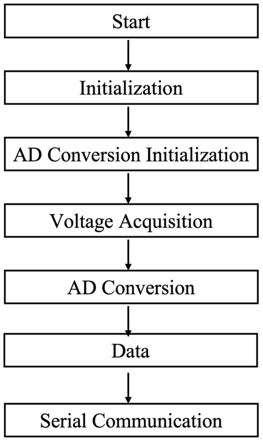
The embedded software implements a deterministic acquisition–processing–transmission pipeline, governed by a state machine. Initialization configures the system clock, critical peripherals (GPIO, interrupts), and the analog-to-digital converter (ADC) with predefined sampling parameters. In the main loop, multi-channel voltage sampling is triggered at fixed intervals. The raw ADC samples are processed through a cascade of a median filter and a moving-average filter to suppress noise, then scaled to physical units using a pre-stored calibration factor. The formatted results are packed into application-layer frames and streamed to the host via a DMA-based UART interface, completing the local sensing-to-reporting sequence.
2.4.2. Host-Software Design
A host application, developed on the platform (Visual Studio 2022, Version 17.9.6), provides communication control, data visualization, and storage. A dedicated communication module manages the serial-port link, receives and parses the embedded data frames, and maintains bidirectional command-data exchange. The graphical interface consolidates real-time waveform display, historical trace review, and system-status monitoring. Acquired data are validated, timestamped, and persisted either to flat files or a local database, enabling offline analysis and report generation. Together, these modules form an integrated PC-side platform for instrument operation and data management.
2.5. Biofunctionalization of the EG-FET Sensor
2.5.1. Electrode Preparation
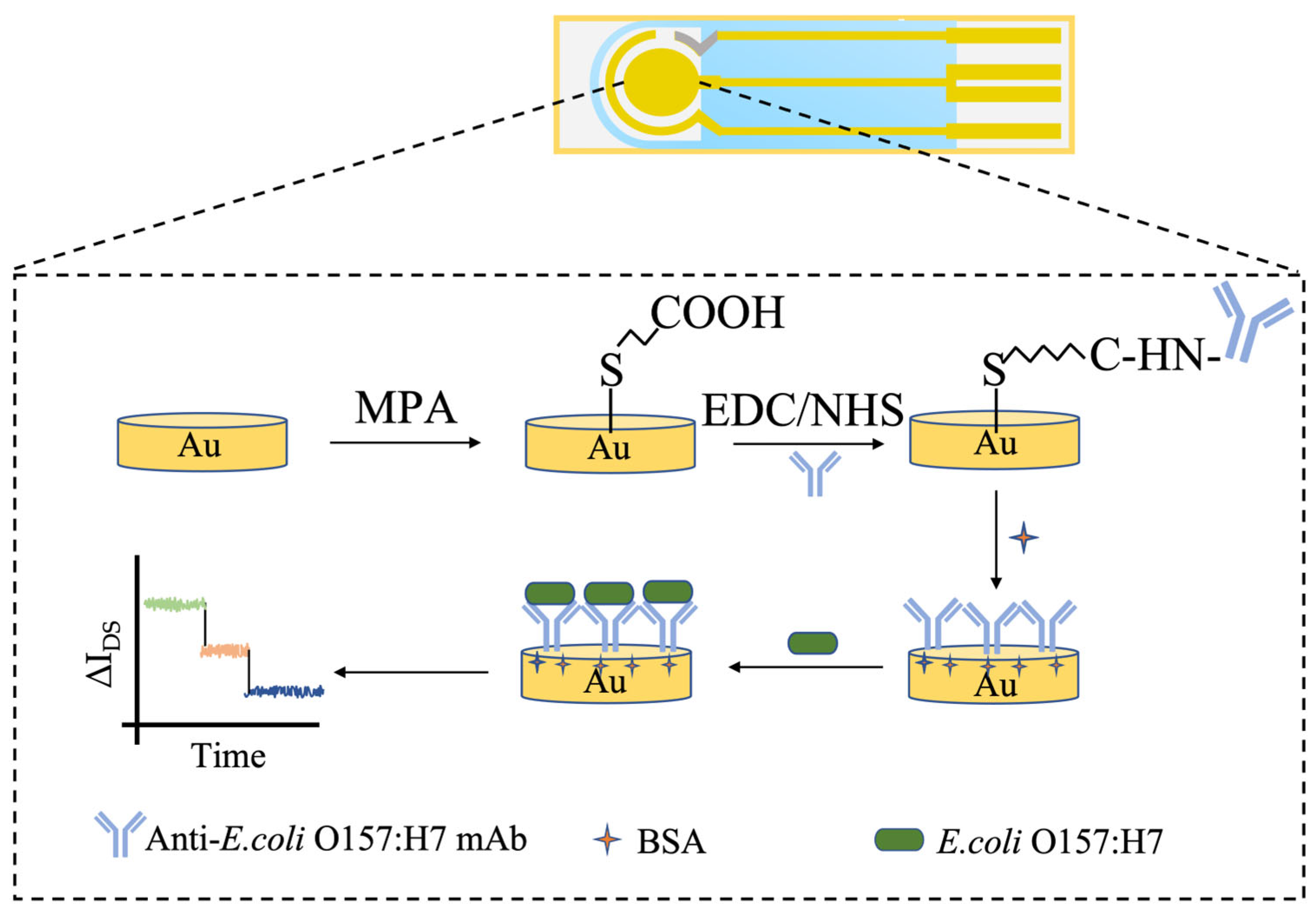
This study employed a 3-mercaptopropionic acid (MPA) self-assembled monolayer method to biofunctionalize the screen-printed gold working electrode of the EG-FET sensor for immobilizing E. coli O157:H7 monoclonal antibodies. A schematic diagram of the process is shown below. All chemical modification steps—including MPA self-assembly, EDC/NHS activation, antibody immobilization, and BSA blocking—were performed simultaneously on the entire three-electrode system (working, counter, and reference electrodes). The specific steps were as follows: First, the screen-printed gold electrode was sequentially cleaned via ultrasonication in anhydrous ethanol and ultrapure water, followed by drying under a stream of nitrogen to ensure a clean electrode surface. The pre-treated gold electrode was then immersed in a 1.25% MPA solution in ethanol and reacted in the dark at room temperature for 18 h. Subsequently, the electrode was removed and thoroughly rinsed with anhydrous ethanol to remove physically adsorbed MPA molecules, resulting in a dense carboxyl-terminated monolayer on the gold surface. The MPA-modified gold electrode was then placed in an aqueous solution containing 100 mM EDC and 20 mM NHS for 1 h to activate the terminal carboxyl groups of MPA, forming reactive esters. Following this, the electrode was gently rinsed with PBS buffer (pH 7.4), each corresponding solution (e.g., 100 µg/mL E. coli O157:H7 monoclonal antibody solution) was precisely dispensed as a 30 µL droplet onto the electrode region using a micropipette, ensuring the droplet completely covers the working electrode. The electrode was then incubated in a humid chamber at 37 °C for 2 h. Under these conditions, the amino groups of the antibody molecules covalently couple with the activated carboxyl groups, achieving stable immobilization of the antibodies on the electrode surface. After the reaction, unbound antibodies were removed by rinsing with PBS buffer. To minimize nonspecific adsorption, the electrode was incubated in a 1% (w/v) bovine serum albumin (BSA) solution for 1 h for blocking. Finally, the prepared electrodes were stored at 4 °C for later use.
2.5.2. Electrode Characterization
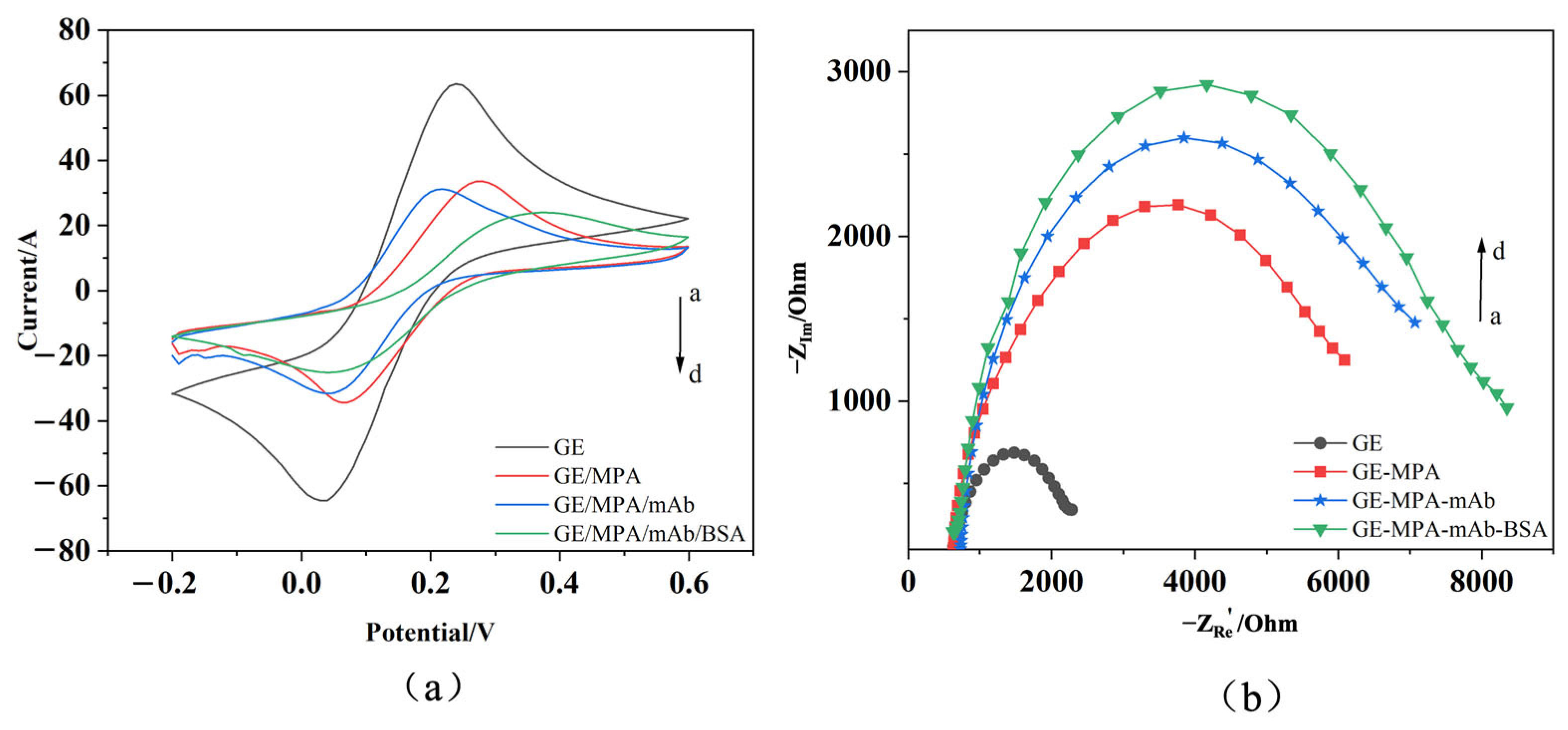
To verify the successful progress of the antibody immobilization process, the electrodes were characterized at each modification stage using cyclic voltammetry (CV) and electrochemical impedance spectroscopy (EIS). All electrochemical measurements were performed on a PalmSens3 electrochemical workstation using a commercially available, integrated screen-printed three-electrode system. This system consists of a gold working electrode, a gold counter electrode, and a screen-printed Ag/AgCl reference electrode. The integrated design ensures that all experiments are conducted on an entirely consistent hardware platform, guaranteeing high comparability of data throughout the entire modification process. Although the gold counter electrode is not completely inert under extreme potentials, its performance remains stable within the limited potential window employed in this study (−0.2 V to +0.6 V vs. Ag/Agcl) and in near-neutral PBS electrolyte, allowing for accurate measurements using the reversible [Fe(CN)6]3−/4− redox probe.
The specific procedure is illustrated in
Figure 1. Characterization System: Characterization was performed in a solution containing [Fe(CN)
6]
3−/
4− (0.005 mol/L). Electrodes at different modification stages were tested in the following sequence: bare gold electrode (GE); gold electrode modified with the MPA self-assembled monolayer (GE-MPA); electrode after monoclonal antibody immobilization (GE-MPA-mAb); and the final immunosensor after BSA blocking (GE-MPA-mAb-BSA).
CV measurements were performed using a screen-printed three-electrode system: a gold working electrode, a gold counter electrode, and a screen-printed Ag/AgCl reference electrode. CV scans were initiated after equilibration at open-circuit potential, with a potential range from −0.2 V to +0.6 V (vs. the integrated Ag/AgCl), a scan rate of 50 mV/s, and a potential step of 0.01 V. After each modification step, the stable voltammogram from the third cycle out of ten consecutive scans was recorded.
EIS measurements were conducted in the same electrolyte and electrode system. Prior to the frequency sweep, the system was equilibrated until the open-circuit potential drift fell below 0.5 mV/s The measurement was performed at a DC bias potential of 0 V with a superimposed sinusoidal AC perturbation of 5 mV amplitude. The impedance spectrum was acquired over a frequency range of 0.1 Hz to 100 kHz, with data points collected logarithmically across this range. The Nyquist plot for each modification-stage electrode was recorded at its respective stable open-circuit potential.
2.6. Preliminary Detection and Data Analysis
All electrical measurements were conducted at room temperature inside an electromagnetic shielding chamber to ensure signal stability. The functionalized sensor was connected to the test system, with its extended gate—the screen-printed gold electrode—serving as the sensing terminal. The sample solution was applied dropwise to its surface, followed by setting the electrical parameters and data acquisition.
2.6.1. Bias Setting and Signal Monitoring Method
The gate voltage (VGS) was fixed near a predetermined threshold voltage (Vth ≈ 1.3 V), while the source-drain voltage (VDS) was fixed at approximately 1 V to ensure the transistor operated in the linear region. This operating point was selected to balance sensitivity and practicality: it provides high transconductance near Vth for effective signal transduction, while the linear region operation offers greater current stability and lower susceptibility to noise compared to the subthreshold regime, ensuring reliable and reproducible measurements. The source-drain current (IDS) was monitored and recorded in real-time as a function of time. When the target analyte binds to the antibodies on the electrode surface, the resulting change in interfacial potential is coupled through the extended gate to the FET channel, thereby modulating IDS. The relative change in IDS (ΔIDS = IDS − I0, where I0 is the baseline current) was used as the signal output for quantitative analysis.
2.6.2. Sensitivity Testing
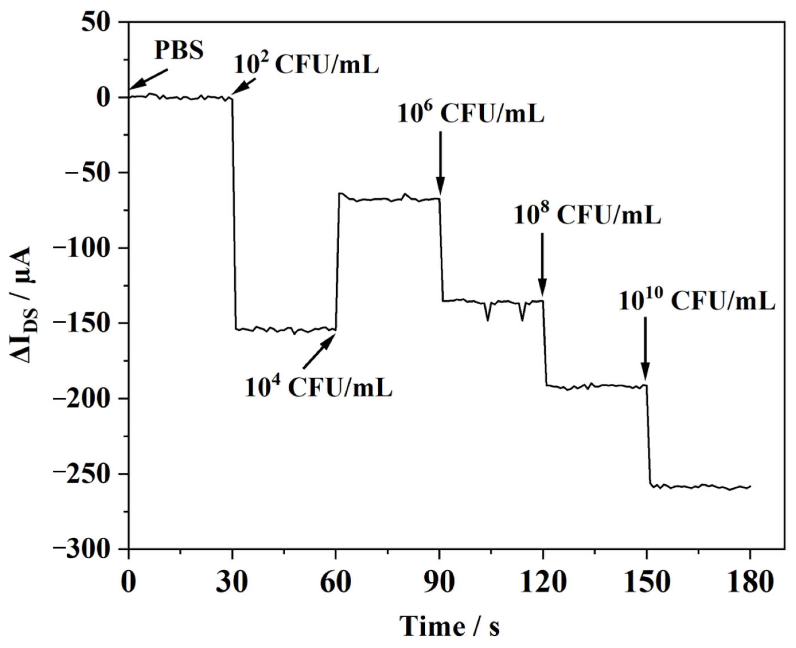
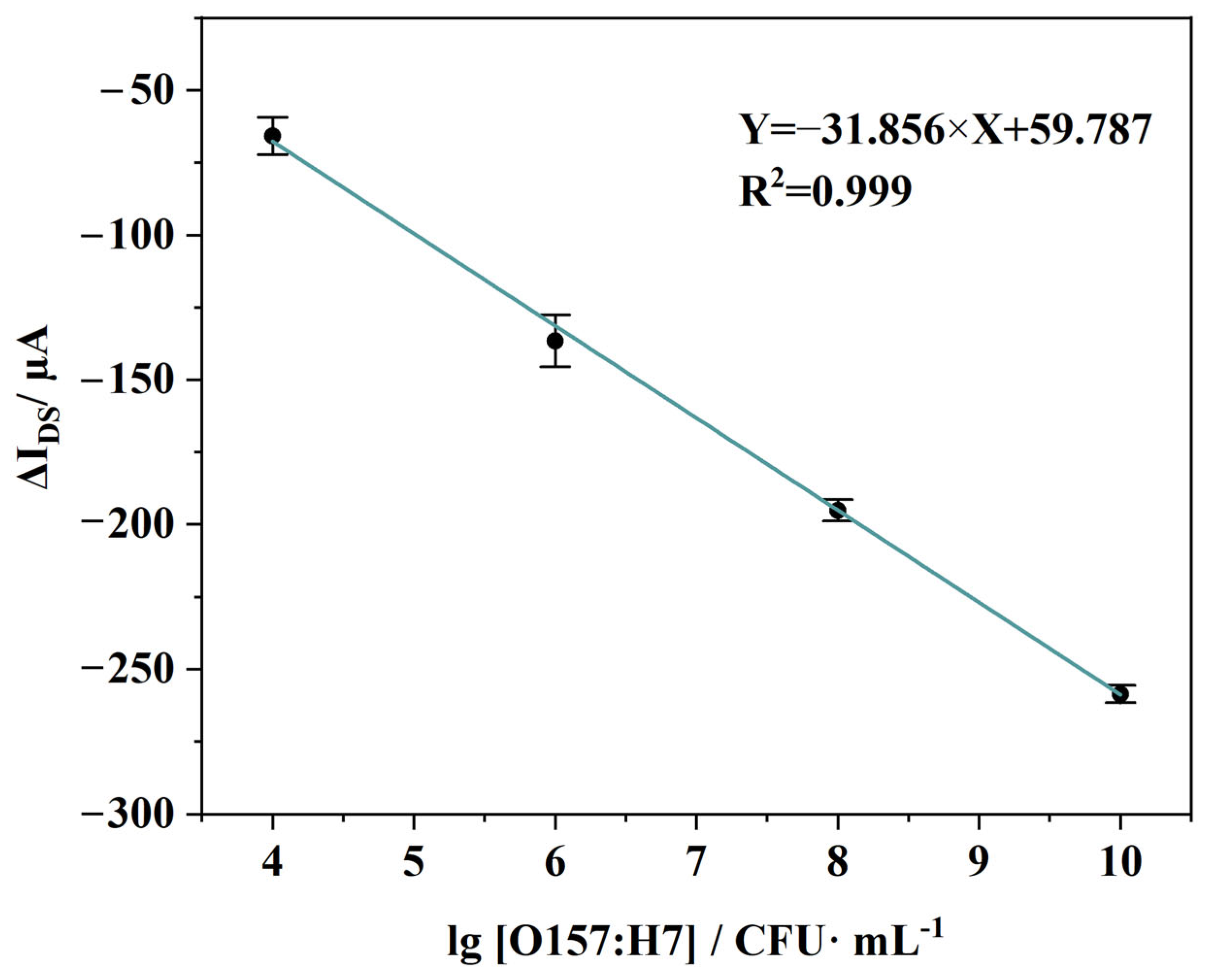
The E. coli O157:H7 bacterial stock was serially diluted with PBS buffer to prepare samples at five concentration points: 102, 104, 106, 108, and 1010 CFU/mL. Following an order from low to high concentration, 50 µL of each bacterial dilution was successively applied to the sensing area. After each application, IDS was continuously monitored until it reached a stable plateau (typically within 5–10 min). All measurements were performed in triplicate. For each concentration measurement, a newly prepared electrode was used. Real-time drain–source current responses curves were plotted using the current data from a 30-s window after signal stabilization for each sample. A standard calibration curve was plotted with the logarithm of bacterial concentration on the x-axis and the corresponding ΔIDS on the y-axis. The limit of detection (LOD) for the sensor was calculated based on this curve.
2.6.3. Specificity Evaluation of the Sensor
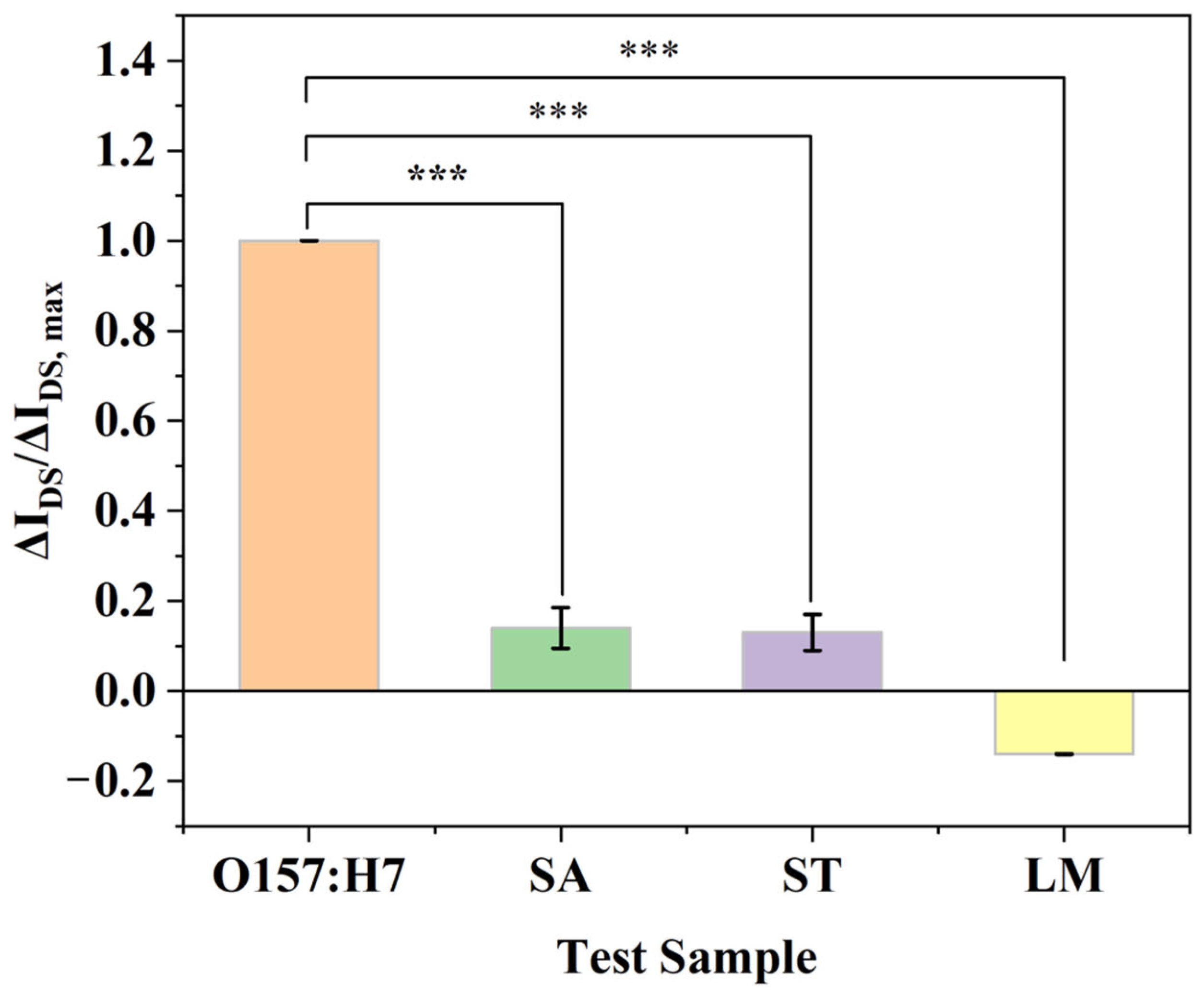
To validate the specific recognition capability of the fabricated sensor toward E. coli O157:H7, this experiment selected three common foodborne interfering bacterial strains for control testing, including: Staphylococcus aureus (SA), Salmonella typhimurium (ST), and Listeria monocytogenes (LM). The experimental setup was as follows: Sensor responses were recorded for E. coli O157:H7, SA, ST, and LM bacterial solutions, as well as for a PBS blank control. Each sample was tested in triplicate. The concentration of E. coli O157:H7 was 105 CFU/mL, while the concentrations of the interfering agents were maintained at least 10-fold higher than that of the target bacterium. All other reaction and detection conditions remained identical. The relative change in drain-source current (ΔIDS) was recorded, and the average values along with standard deviations for each group were calculated. The response signals of the target bacterium were then compared against those of the interfering strains.
4. Discussion
This study demonstrates an integrated EG-FET biosensing system for the detection of
E. coli O157:H7, the performance of which has been verified under laboratory conditions. To fully interpret the significance of these results and clarify the position of this work, it is necessary to discuss them within a broader research context and application prospects. First, the observed sensing signal originates from interfacial potential changes induced by bacterial capture, but this process is significantly constrained by the Debye screening effect. When the concentration of PBS increases from 0.1 × 10
−3 mol/L to 10 × 10
−3 mol/L, the Debye length decreases from 7.0 nm to 0.7 nm. Typically, the length of receptor molecules immobilized on the device ranges from 5 to 15 nm, and their distance from the sensing surface is between 2 and 12 nm [
28,
29]. Consequently, the size of target molecules and their distance from the device surface often exceed the Debye length of the FET, leading to partial charge shielding of the target molecules and thereby reducing detection sensitivity. This provides a theoretical basis for understanding the current sensitivity limits and indicates a future pathway for systematically optimizing buffer ionic strength to improve the signal-to-noise ratio and detection limit.
In terms of innovation, the core contribution of this work lies in the realization of an EG-FET integrated solution that balances performance, cost, and practicality. Unlike many conventional designs, the extended-gate architecture adopted in this study physically separates the sensitive interface from the transistor core. This not only enhances device robustness and flexibility in interface modification but is also key to achieving low-cost, disposable extended gates. Particularly important is our preliminary cost analysis, which shows that the hardware cost of the entire setup can be controlled at approximately USD 5.6, while the cost of the screen-printed gold electrode consumed per test is about USD 1.4. This establishes a highly competitive foundation for subsequent productization. In the future, exploring lower-cost substrate materials such as carbon electrodes will be a major focus for further reducing the cost per test and promoting practical application.
Nevertheless, we must objectively acknowledge that a gap remains between the current stage of this research and the goal of “field applicability.” To date, all experiments have been conducted under controlled laboratory conditions, lacking performance validation in real-world environments such as battery-powered operation, temperature and humidity fluctuations, or long-term continuous operation. Therefore, statements regarding the stability and robustness of the system for field deployment remain somewhat speculative at this stage. This clearly delineates the directions that future research must encompass: namely, long-term stability testing, environmental drift characterization, and validation with actual complex samples. Only through such rigorous evaluation can the current high-performance laboratory prototype be transformed into a reliable field device. Furthermore, to bridge the gap between the sensor’s reliable quantitative detection range (104–1010 CFU/mL) and the stringent regulatory thresholds typically required in practical applications (e.g., 102–103 CFU/mL in the field of food safety), future work may need to introduce a sample pre-concentration step prior to detection.
In summary, this study not only verifies the feasibility of the integrated EG-FET system for pathogen detection, but also, through in-depth analysis of its operating mechanism, cost structure, and application limitations, outlines a clear roadmap for technological development. Future efforts should focus on overcoming performance bottlenecks via interfacial physicochemical optimization, reducing manufacturing costs through material and process innovation, and ensuring reliability in practical scenarios via stringent environmental testing, thereby ultimately achieving the transition from a laboratory concept to a field-ready solution.
5. Conclusions
In this work, we developed a compact EG-FET integrated sensing system that combines an extended-gate sensing electrode, a low-noise readout/acquisition module, and host-side visualization software into an end-to-end prototype for on-site biosensing. By integrating bias control, weak-current conditioning, digital sampling, and real-time data display within a single system, the proposed implementation reduces dependence on benchtop instrumentation and provides a practical engineering route toward deployable FET-based detection. By covalently immobilizing E. coli O157:H7 monoclonal antibodies on the Au extended gate, we constructed a target-specific immunorecognition interface. Measurements in buffer demonstrated a concentration-dependent electrical response, with a linear calibration behavior validated over 104–1010 CFU/mL, and a theoretical limit of detection (LOD) of 9.55 CFU/mL, supporting quantitative detection within this range. The specificity experiments further confirmed that the signal response to the target bacterium (E. coli O157:H7) (ΔIDS/ΔIDS, max = 100%) was significantly higher than that to non-target strains, with a highly statistically significant difference between the two groups (p < 0.001), demonstrating the high specificity of the constructed immunorecognition interface.
This study primarily establishes system feasibility and integration methodology. Future work will focus on the following key directions: optimizing buffer ionic strength to mitigate the Debye screening effect; enhancing the system’s low-concentration precision, long-term stability, and drift resistance; and conducting rigorous robustness evaluation and application-oriented testing. These efforts are directed toward advancing the system toward practical deployment in on-site diagnostic scenarios such as food safety monitoring.