Article

Charge Trapping Effects on n−MOSFET Current Mirrors Under TID Radiation

1
Laboratory of Electronics and Microelectronics (LEMM), University of Monastir, Monastir 5019, Tunisia
2
Institute of Information and Communication Technologies, Electronics and Applied Mathematics (ICTEAM), Université Catholique de Louvain (UCL), Place du Levant 3, 1348 Louvain-la-Neuve, Belgium
*
Author to whom correspondence should be addressed.
Micromachines 2025, 16(9), 1064; https://doi.org/10.3390/mi16091064
Submission received: 12 August 2025 / Revised: 2 September 2025 / Accepted: 6 September 2025 / Published: 20 September 2025

Abstract

This study aims to evaluate the effects of total ionizing dose (TID) radiation on the performance of n−MOSFET current mirrors. We propose an ovel experimental approach to analyze the interaction between charge trapping in the MOSFET gate oxide and the resulting current mirror degradation by subjecting devices to TID doses from 50 krad(Si) to 300 krad(Si) using a 60Co gamma source Experimental data show that threshold voltage shifts by up to 1.31 V and transconductance increases by 27%. This degradation leads to this a reduction of more than 10% in current mirror output accuracy occurs at the highest dose. These quantitative criteria establish a clear benchmark for assessing the impact of TID on current mirror performance. These effects are attributed to positive charge trapping in the gate oxide and at the Si–SiO2 interface induced by ionizing radiation. This study focuses exclusively on radiation effects; electrical stress phenomena such as over−voltage or electrostatic discharge (ESD) are not addressed. The results highlight the critical importance of accounting for TID effects when designing high−performance n−MOSFET current mirrors for radiation−hardened applications.

1. Introduction

As semiconductor technology has advanced, integrated circuit (IC) applications have shown significant progress, while harsh environments, particularly space, have revealed critical challenges for device performance. Statistical analyses of satellite failures indicate that a major portion originates from electronic circuits rather than mechanical components [1,2]. Among these electronic circuits, MOS−based devices—including transistors, amplifiers, and current mirrors—play a pivotal role in analog and mixed−signal systems. Their proper functioning is crucial for tasks such as signal processing, biasing, and control in spaceborne electronics. Space radiation poses a significant threat to the reliable operation of electronic circuits, particularly MOS devices [3]. Exposure to radiation can induce Single−Event Effects (SEEs) and total ionizing dose (TID) effects, where TID refers to the cumulative ionizing radiation absorbed by the device over time, and SEEs correspond to instantaneous disruptions caused by energetic particles [3]. While much research has focused on SEEs, studies addressing TID mechanisms remain limited.
An inverter, as a fundamental building block of MOS circuits [4], is crucial for understanding overall system radiation tolerance. The TID effect is characterized by cumulative degradation of device performance due to high−energy photons and charged particles [5,6,7], primarily through positive charge accumulation in the oxide layer and interface trap formation at the SiO2/Si interface [8,9]. Unlike SEEs, TID cannot be completely mitigated due to its cumulative and physical nature. For electronic devices such as amplifiers, comparators, and voltage references, TID−induced shifts in threshold voltage or transconductance can propagate through circuits, causing timing errors, output drifts, and decreased amplification accuracy. Recent studies have modeled TID effects in advanced FDSOI technologies [10] and provided comprehensive analyses of radiation effects and soft errors in ICs [11].
Even at low doses, MOS devices are highly susceptible to radiation [12,13,14]. Beyond immediate performance impacts, long−term reliability post−radiation is critical, especially for space missions [15]. While TID is a key concern, intrinsic aging mechanisms such as Hot Carrier Injection (HCI), Bias Temperature Instability (BTI), and Time−Dependent Dielectric Breakdown (TDDB) [16,17,18,19] also affect device longevity independently. Though interface traps appear in these studies, their origins are typically process−related, thermal, or bias−induced, rather than radiation−induced. Nevertheless, TID and intrinsic mechanisms can produce similar effects, such as threshold voltage shifts and increased leakage, emphasizing the need for comprehensive reliability modeling.
Electrical stress, including BTI, can degrade MOS device parameters such as threshold voltage and transconductance [20,21,22,23,24]. When combined with TID, degradation may be exacerbated, leading to cascading effects in both analog and digital circuits. Accurate biasing is essential for proper IC operation [25,26,27]. Traditional CMOS dividers, based on resistors or transistors, have limitations due to process, voltage, and temperature dependencies [28]. Current mirrors (CMs) have emerged as efficient biasing elements capable of amplifying or transferring currents while providing better performance in terms of current gain, input−output impedance, and power consumption [29,30]. In electronic systems, current mirrors are frequently used to generate stable reference currents, drive active loads, and implement analog signal processing blocks, making them critical indicators of radiation−induced degradation. These characteristics make current mirrors essential for providing stable reference currents in analog circuits, which is particularly important when assessing TID−induced degradation in n−MOSFET devices.
This work focuses on investigating the TID−induced degradation of n−MOSFET−based current mirrors, with an emphasis on charge trapping mechanisms in the oxide layer under different biasing conditions. While electrical stress phenomena such as over−voltage or electrostatic discharge (ESD) are excluded, this study quantifies threshold voltage shifts and transconductance degradation under TID doses from 50 krad(Si) to 300 krad(Si) using a ^60Co gamma source, linking these effects directly to current mirror performance.
This paper is organized as follows: Section 1 provides a brief introduction and review of related works; Section 2 presents time−dependent hole trapping models and their impact on flat−band voltage shifts in the oxide layer; Section 3 describes reliability analyses of TID effects on n−MOSFET current mirrors; and Section 4 summarizes conclusions and perspectives.

2. Hole Trapping Models and Flat−Band Voltage Shift

2.1. Hole Trapping

Due to ionizing radiation, the charge build−up in the oxide layer arises from the generation of electron−hole pairs and subsequent hole trapping. This supposes that de−trapping of holes is neglected. Another simplifying hypothesis can also be adopted. It consists of assuming that the distribution of hole traps is uniform. This leads to the rate equations that govern the trapping of holes as follows:
p T r a p p e d ( x , t ) t = d γ d t v p F r e e ( x , t ) x
p T r a p p e d ( x , t ) t = σ v p F r e e x , t [ N T p T r a p p e d x , t ]
where γ denotes the rate of generation of electron−hole pairs per unit volume, v is the velocity of holes, σ defines the capture cross−section of the trap sites, and NT is the density of hole traps throughout the oxide layer. Under this form, it is worth noting that Equations (1) and (2) can be solved exactly only when the term γ is not accounted for. An illustration is given in the report of Ning [30].Later, the charge build−up in MOS structures has been undertaken by Viswanathan [31].Interestingly, the rate equations were solved for γ non null, but in two limiting cases:
i—The density of trapped holes is not large compared to the total number of hole traps.
ii—The trapping efficiency is much lower than the rate of electron−hole generation. The solutions thus adopted in the last case can be combined under a general form:
P T r a p p e d h o l e s x , t = N 1 e x λ ,
with {N = γ;   λ =   1 N T } in the first limiting case, and {N = N T ;   λ     =   1 σ γ } in the second one.
The origin of the x−axis is fixed at the gate−dioxide interface. It has been found that the density of trapped holes is exponentially high, with a saturated trend towards the silicon−dioxide interface. In Equation (3), λ can be interpreted as the probability per unit length of a hole being trapped within the oxide layer under irradiation.

2.2. Time−Dependent Hole Trap Density and Transconductance

Because of hole trapping, a potential shift can occur at the oxide terminal, and its expression versus trapped holes p(x,t) is given by V F B t o x , λ = q ε 0 ε r o x 0 t o x x P T r a p p e d x , t d x , where q is the electronic charge, Ɛrox represents the dielectric constant of the oxide layer, Ɛ0 is the permittivity of free space, tox is the oxide thickness, and FB is a subscript representing a flat band. In evaluating the integral as a function of tox, the mean trapping free length is treated as a parameter.
The calculation of F F B t o x , λ under a positive bias voltage leads to the following expression:
V F B t o x , λ = q N t o x 2 Ɛ 0 Ɛ r o x F ( t o x λ )
with
F t o x λ = 1 2 + ( t o x λ + 1 ) t o x 2 λ 2 e t o x ʎ 1 t o x 2 λ 2
For a fixed thickness of the oxide layer and taking the mean trapping free length λ to be less than tox, the pre−exponential factor N will correspond to the hole trap density NT. On the other hand, by identifying ΔVFB for the threshold potential shift ΔVth (TID), as measured under irradiation, we can derive the TID−dependent oxide trapped charge density from the following relation:
N T T I D Ɛ 0 Ɛ r o x q t o x 2 F ( t o x λ ) V t h T I D
To further improve the trapping charge model, it is required to assume the existence of an additional sheet charge near the Si/SiO2 interface, related to surface states or arising from shallow traps. The contribution of all these charge states can be approximately accounted for by defining the effective density of hole traps as follows: NTEFF = (1 + α)NT, where α represents a centesimal percent factor, which is negative if the additional sheet charge is predominated by electron−traps or positive in the reverse case. Here, this correction is not taken into account.
A great deal of interest is also paid to the transconductance parameter. Let VGS (t, TID) = VGS(t, TID = 0) + ∆VFB(t, TID) be the gate−to−source bias voltage under gamma radiation. Similar to the hole trap density, the time−dependent transconductance is expressed as follows:
g m T I D = g m ( T I D = 0 ) 1 ɳ [ q t o x 2 Ɛ 0 Ɛ r o x F ( t o x λ ) ] N T ( T I D )
where ɳ is an empirical factor, and gm (TID = 0) is the initial transconductance before irradiation. Notably, ɳ can be determined from the measured gm (TID) and the calculated NT(TID) using the following relation:
ɳ = 1 g m ( T I D = 0 ) g m ( T I D ) q t o x 2 Ɛ 0 Ɛ r o x F ( t o x λ ) N T ( T I D )

3. Reliability Analyses of Total Ionizing Dose Effects on n−MOSFET Current Mirrors

3.1. TID−Induced Electrical Degradation of an n−MOSFET

The n−MOSFET under investigation was fabricated using 1µm channel Silicon−On−Insulator (SOI) technology, with a gate oxide thickness of tox = 25 nm. Devices were prepared on a standard SOI substrate and underwent pre−irradiation conditioning to ensure uniformity. Details on the epitaxial growth and annealing process are provided in ref. [32]. This study focuses solely on TID effects, excluding electrical stress phenomena such as over−voltage or electrostatic discharge (ESD), to isolate the impact of TID−induced charge trapping on threshold voltage and transconductance. Long−term, time−dependent post−irradiation measurements were not conducted and will be addressed in future work to assess device reliability under prolonged TID exposure.
Concerning VGS−IDS characteristics, measurements were performed before and after irradiation. The n−MOSFET devices were subjected to gamma irradiation using a 60Co source. The total ionizing dose (TID) was incrementally increased up to 300 krad(Si). Measurements were performed at room temperature before and after each irradiation step, without any annealing before for VDS fixed at 50 mV in the linear regime and VDS = 3 V in the saturation regime. As it is seen, the threshold potential shows a negative shift with increased TID, and the relevant data are found to be fitted by the polynomial law:
𝚫𝐕𝐓𝐡= 𝟏.𝟔𝟗 – 𝟏𝟐𝟒𝟏𝟎 − 𝟓 × 𝐓𝐈𝐃
where Vth (TID = 0) = 1.69 V. From the measured ΔVth(TID), we deduced the density NT of induced hole traps as a function of TID using Equation (6). To highlight the impact of TID radiation, pre− and post−irradiation values of threshold voltage and transconductance were compared. The degradation of device performance is directly linked to hole trapping in the gate oxide. Ionizing radiation generates electron−hole pairs in the oxide, and the holes are captured at trap sites, resulting in a net positive charge. Simultaneously, interface traps form at the Si–SiO2 interface, further affecting the threshold voltage and transconductance. These trapped charges reduce effective gate control over the channel, leading to a measurable decrease in current mirror accuracy and overall device performance, as reflected in the observed Vth and gm shifts.
The threshold voltage decreased from Vth = 1.69 V before irradiation to 1.32 V at the highest dose of 300 krad(Si), while transconductance increases from gm = 1.099 µS to 1.40 µS. These comparisons clearly illustrate the extent of TID−induced degradation in the n−MOSFETs and provide quantitative evidence for the charge trapping effects discussed above. The detailed results are summarized in Table 1.
The mean trapping free length is fixed at λ = 5 nm, which corresponds to   e t o x λ = 6 × 10 3 . Results are depicted in Figure 1 for an interfacial charge plot NT2D = NT× tox. It is clear that there is a gradual increases in the amount of trapped holes as the total ionizing dose increases. As it has also been mentioned, the interfacial density of hole traps is related to TID by the following fitting relation:
𝐍𝐓𝟐𝐃(𝟏𝟎𝟏𝟏 𝐜𝐦−𝟐) = −𝟑𝟓𝟔 × 𝟏𝟎−𝟓+ 𝟐𝟑𝟖 × 𝟏𝟎−𝟓× 𝐓𝐈𝐃 − 𝟏. 𝟕𝟖 × 𝟏𝟎−𝟕× 𝐓𝐈𝐃𝟐 in cm−n
In addition to NT, the graph shows the corresponding threshold potential versus TID. A proposed explanation is that exposure to relatively high TID levels induces defects in the MOS capacitance. This can make it difficult for electrons to flow into the conductive channel. Microscopically, an accumulation of holes reduces the switching speed of the MOSFET. As a peculiar feature, the threshold potential shift is found to be more significant at lower TID doses. Additionally, an increase in the threshold voltage can enhance the power consumption. Another fundamental parameter of the n−MOSFET that is impacted by gamma radiation is transconductance. Measurements of this parameter have led to an increasing trend versus TID. The data points are depicted in Figure 2 with the obtained fitting relation:
𝐠𝐦(𝐓𝐈𝐃) = 𝟏.𝟏𝟏 + 𝟏.𝟎𝟐𝟏𝟎−𝟑 × 𝐓𝐈𝐃 n µS
From the measured gm(TID) and NT(TID), we have computed the empirical factor ɳ (TID). Results are found to be fitted using the following equation:
ɳ(𝟏𝟎𝟏𝟓 𝐦−𝟐) = −𝟎.𝟎𝟒𝟐 − 𝟑.𝟑𝟓 × 𝟏𝟎−𝟓× 𝐓𝐈𝐃 + 𝟕 × 𝟏𝟎−𝟕 × 𝐓𝐈𝐃𝟐−𝟏.𝟒𝟓 × 𝟏𝟎−𝟗 × 𝐓𝐈𝐃𝟑
These observed degradations in threshold voltage Vth and transconductance gm can be directly linked to hole trapping mechanisms in the gate oxide and the formation of interface traps at the Si–SiO2 interface. As the total ionizing dose increases, the accumulation of positive charges in the oxide layer reduces the effective gate control over the channel, resulting in a negative shift in Vth th. Simultaneously, trapped charges and interface states scatter carriers, decreasing the channel mobility and consequently the transconductance. This correlation between charge trapping and electrical parameter degradation provides a mechanistic explanation for the performance loss observed in n−MOSFETs under TID irradiation [30,31].
For the conductance, however, we did correlate this parameter with the charge build−up in the oxide. Calculations were performed using TID as an auxiliary variable, which has led to the plot of Figure 3. As it can be noticed, the conductance increases with TID according to the following fitting relation:
𝐠𝐝(𝐓𝐈𝐃) = 𝟏.𝟏𝟔𝟏𝟎−𝟓+ 𝟐.𝟖𝟑𝟏𝟎−𝟖 × 𝐓𝐈𝐃 − 𝟏𝟕𝟏𝟏𝟎−𝟏𝟏 × 𝐓𝐈𝐃
The conductance increases with TID, reflecting enhanced leakage paths induced by oxide charge trapping. Scientific notation is used for small conductance values to improve readability.

3.2. Electrical Degradation Mechanisms in n−MOSFET Current Mirrors

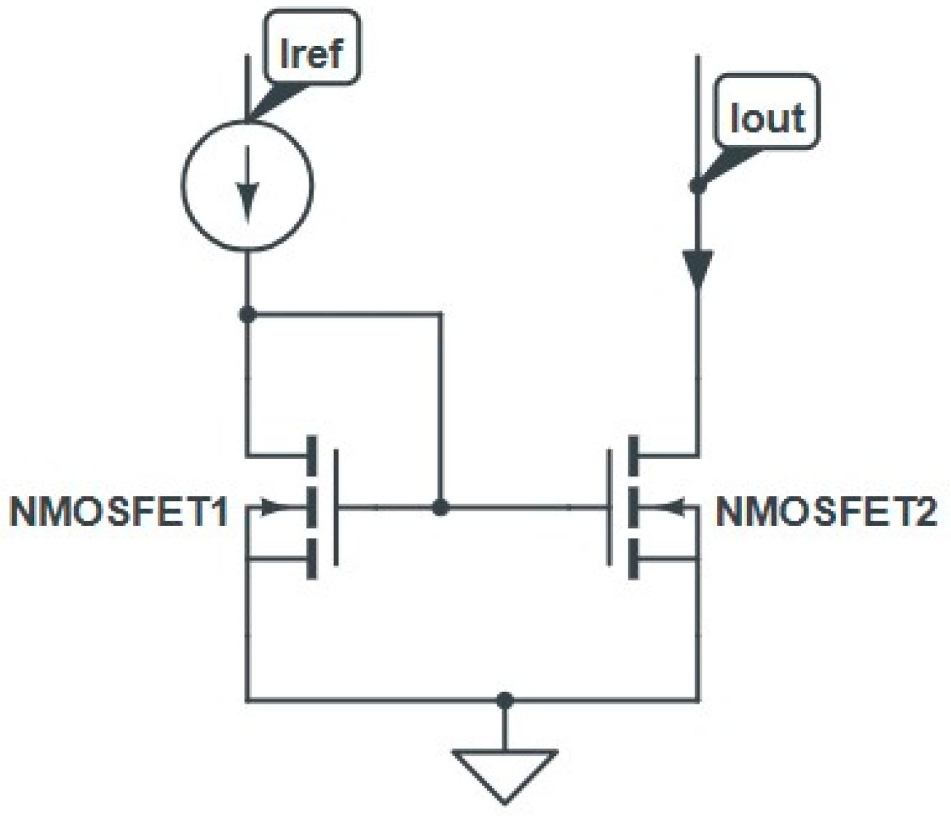
The biasing of the CM as it used in AMS integrated circuits [29] is shown in Figure 4, with its dynamical equivalent scheme. It is constructed using two n−MOS transistors labeled M1 and M2.The diode−connected transistor M1 operates in saturation regime and converts the reference current IeEF into a corresponding gate−to−source voltage VGS1. The transistor M2 is a regenerating module that gives rise to an output current IOUT. If both the transistors M1 and M2 are matched, the gate−to−source biases VGS1 and VGS2 are equal, and then IeEF would be perfect at the output of CM. Under saturation conditions, the reference and output currents are given by the following set of electrical equations: I R E F = 1 2 µ n C o x ( w L ) 1 V G S 1 V T H 1 2 and I O U T = 1 2 µ n C o x ( w L ) 2 V G S 2 V T H 2 2 .
Where µn is the electron mobility, Cox denotes the MOSFET capacitance per unit area, and VTHi = 1.2 is the threshold potential of the n−MOSFETs. From IREF and Iout, we can derive the current gain. This parameter is undoubtedly affected by irradiation. Let TID1 = x TID and TID2 = (1 − x)TID, with 0 ≤ x ≤1 being the total ionizing doses for the MOSFET1 and MOSFET2 transistors, respectively. The current gain of the SCM reads is as follows: A i ( x , T I D ) S C M = ( w L ) 2 ( w L ) 1 × V G S V T H [ 1 x T I D   ] V G S V T H [ x T I D ] , where x represents a dissymmetric percent that characterizes the TID contamination of the n−MOSFETs. The calculation of AiSCM(x.TID) has led to a graph of the current gain of an n−MOSCM versus x for different TIDs, as illustrated in Figure 5. We note that the current gain is a measure of how much an n−MOSFET mirror can replicate a current signal. The plot also shows that the current gain decreases as TID increases. This is because exposure to ionizing radiations damages the MOSFET’s gate oxide and reduces the ability of the gate to control the flow of current between the source and drain. As a further observation, the decreasing rate in current gain is found to change with the dissymmetric percent. Analytically, the x− and TID− dependent current gain are fitted according to the following equations:
A i S C M x , T I D = a 0 + a 1 × T I D + a 2 × T I D 2
a 0 x = 1.017 + 0.00388 × x + 2.14 10 17 × x 2
a 1 x = 0.024 0.0088 × x + 5 10 6 × x 2
a 2 x = 0.057 + 0.00229 × x + 8.35 10 6 × x 2
Usually concerning the dissymmetric percent, it is worth noticing that a relatively high value of this coefficient means that the n−MOSFET gate−oxide becomes more asymmetric. This makes it sufficiently susceptible to submit damages from ionizing radiation. Two other important parameters garnered interest. They were input and output impedances of the SCM. According to the TD1 and TD2 defined above, both impedances are expressed as follows:
R i n S C M x , T I D = 1 g m x T I D
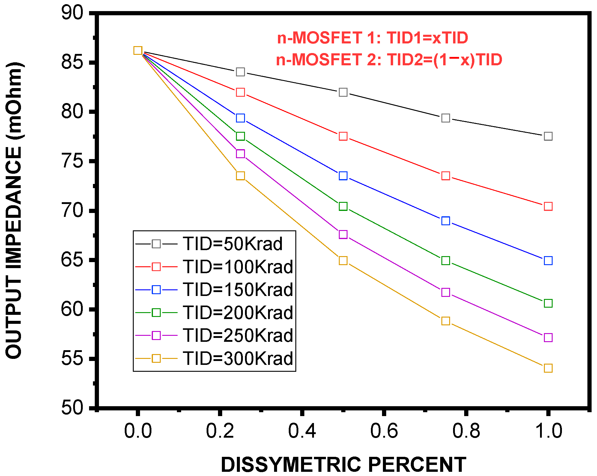
R o u t S C M x , T I D = 1 g d [ ( 1 x ) T I D ]
Using Equations (14) and (15), we calculated RSCMin and RSCMout versus x for different TIDs ranging from 50 Krad to 300 Krad. As it can be seen, Figure 6 shows a clear positive correlation between the dissymmetric percent and input impedance, independently of the TID level. Such an increase in impedance is assigned to the disruption of conduction paths produced by asymmetry. Moreover, the effect of TID is significant, suggesting that defects created by radiation also reinforce the CM resistance at input. The graph in Figure 7, however, shows how the output impedance is affected by the two factors. As it is seen, the impedance at output decreases with an increase in asymmetry percentage and total ionizing dose. The following set of expressions describes the analytical fitting of of RSCMin(x, TID) and RSCMout(x, TID):
R i n S C M x , T I D = a 0 + a 1 × T I D + a 2 × T I D 2
a 0 x = 1.11 1.55 10 18 × x
a 1 x = 7.91 10 4 0.00157 × x
a 2 x = 0.047 6.45 10 4 × x
R o u t S C M x , T I D = a 0 + a 1 × T I D + a 2 × T I D 2
a 0 x = 86295.45 0.63 × x
a 1 x = 1679.69 173.37 × x
a 2 x = 4684.79 + 83.85 × x
In a concluding remark, the input and output impedances of a perfect current mirror should be very low and large enough, respectively. This suggests that degradations induced by geometric dissymmetry and the effect of ionizing radiation have a negative impact on CM’s ability to deliver more current to the load. It is then required to characterize these degradations in an attempt to develop an equivalent model that includes the parameter related to a radiation−hardened environment. In practice, SCMs are suitable for low−voltage applications. Technologically, the limited usage of SCMs contributed to their low output impedances. Some remedies were conceived to further improve the impedance at output. They consisted of Widlar CM [28] and cascade CM [27,28] designs. As it has been found, the output impedance of an SCM is increased due to Widlar and cascade arrangements based on the following ratios:
R o u t W M C R o u t S C M = 1 + R g m 2 and   R o u t C a s c o d e   C M R o u t S C M = r d s 3 g m 3 r D S 2 g D S 1
In conclusion, it is worth mentioning that the cascade technology can open a promising way to construct electronic applications with low−voltage operation and low power consumption. But the use of complex configurations needs a multitude of elementary transistors. Because of different operating regimes, the cascade CMs could exhibit a mismatching in current and voltage between the input and the output. Exposure to ionizing radiations could also lead to further degradations.

3.3. Comparative Analysis with Literature

A comparison of our results with previous studies on TID effects in n−MOSFET devices is provided in Table 2. This table highlights differences in device types, TID dose ranges, measured parameters, and observed degradations, illustrating that n−MOSFET current mirrors experience substantial threshold voltage shifts and output accuracy loss compared to conventional MOSFETs reported in the literature.

4. Conclusions

In this study, we have investigated the combined effects of TID radiation and electrical stress on the performance of current mirrors based on n−MOSFETs. Through experimental measurements and simulations using LTspice, we inferred that both TID radiation and electrical stress independently contribute to the degradation of the current mirror’s accuracy, matching, and electrical performance. Our results demonstrate that TID radiation primarily causes charge trapping in the gate oxide, leading to a threshold voltage shift, while electrical stress provokes these effects by further altering device characteristics, such as transconductance and current gain. Consequently, current mirrors subjected to both TID radiation and electrical stress show significant changes in their characteristics, leading to a loss of precision and reliability. The findings highlight the importance of considering both radiation and electrical stress in the design and qualification of n−MOSFET current mirrors for radiation−hardened applications. To mitigate these effects, it is essential to explore design optimizations such as improved radiation−hardened materials, fault−tolerant circuit topologies, and enhanced device−shielding techniques. Further research should focus on developing a complete model to predict the combined impact of TID radiation and electrical stress. This undoubtedly allows to design more accurate MOSFET−circuits for high gamma−ray doses.

Author Contributions

Conceptualization, S.A.; methodology, M.M.; validation, M.M.; investigation, M.M.; data curation, S.A.; writing—original draft, D.A.; writing—review and editing, L.A.F.; visualization, D.A. All authors have read and agreed to the published version of the manuscript.

Funding

This work was supported by UCLouvain (Université catholique de Louvain).

Data Availability Statement

Data are contained within this article.

Conflicts of Interest

The authors declare no conflicts of interest.

References

  1. Zhang, S.; Shi, J.; Wang, J.L. Satellite on-board failure statistics and analysis. Spacecr. Eng. 2010, 19, 41–46. [Google Scholar]
  2. Cao, Y.; Wang, M.; Zheng, X.; Zhang, E.; Lv, L.; Wang, L.; Ma, M.; Lv, H.; Wang, Z.; Wang, Y.; et al. Combined Effect of TID eadiation and Electrical Stress on NMOSFETs. Micromachines 2022, 13, 1860. [Google Scholar] [CrossRef]
  3. Gao, T.; Yin, C.; Chen, Y.; Chen, R.; Yan, C.; Liu, H. Simulation of Total Ionizing Dose Effects Technique for CMOS Inverter Circuit. Micromachines 2023, 14, 1438. [Google Scholar] [CrossRef]
  4. Bonaldo, S. TID effects in highly scaled gate-all-around Si nanowire CMOS transistors irradiated to ultrahigh doses. IEEE Trans. Nucl. Sci. 2022, 69, 1444–1452. [Google Scholar] [CrossRef]
  5. Wang, S. Research and Modeling of Irradiation Characteristics of Ultra-Deep Submicron Devices. Ph.D. Thesis, Changchun University of Technology, Changchun, China, 2010. [Google Scholar]
  6. Zeng, C.; Li, X.; Gao, L. Research on High Temperature Characteristics of 28 nm Ultra-Thin FDSOI. Microelectronics 2021, 51, 577–581. [Google Scholar]
  7. Solano, J.; Spear, M.; Wallace, T.; Wilson, D.; Forman, F.; Esqueda, I.S. Total Ionizing Dose Response of Commercial 22nm FD-SOI CMOS Technology. In Proceedings of the 2022 IEEE Radiation Effects Data Workshop (REDW) (in conjunction with 2022 NSREC), Provo, UT, USA, 18–22 July 2022; pp. 1–5. [Google Scholar] [CrossRef]
  8. Schrimpf, R.D.; Fleetwood, D.M. Radiation Effects and Soft Errors in Integrated Circuits and Electronic Devices; World Scientific: Singapore, 2004. [Google Scholar]
  9. Nasr, A.; Ashour, M. Experimental Studies for the Evaluation of Non-Ionizing Radiation Levels. In Proceedings of the Second All African IRPA Regional Radiation Protection Congress, Ismailia, Egypt, 22–26 April 2007; p. 223. [Google Scholar]
  10. Nasr, A. Effect of ionizing radiation on the characteristics of photodetectors. In Proceedings of the Second All African IRPA Regional Radiation Protection Congress, Ismailia, Egypt, 22–26 April 2007; p. 231. [Google Scholar]
  11. Prakash, G.; Ganesh, P.; Nagesha, Y.N.; Umakanth, D.; Arora, S.K.; Siddappa, K. Effect of 30 MeV Li3+ ion and 8 MeV electron irradiation on N-channel MOSFETs. Radiat. Eff. Defects Solids 2002, 157, 323. [Google Scholar] [CrossRef]
  12. Oldham, T.; McLean, F. Total ionizing dose effects in MOS oxides and devices. IEEE Trans. Nucl. Sci. 2003, 50, 483–499. [Google Scholar] [CrossRef]
  13. Chen, D.; Forney, J.D.; Pease, R.L.; Phan, A.M.; Carts, M.A.; Cox, S.R.; Kruckmeyer, K.; Burns, S.; Albarian, R.; Holcombe, B.; et al. The Effects of ELDRS at UltraLow Dose Rates. In Proceedings of the 2010 IEEE Radiation Effects Data Workshop, Denver, CO, USA, 20–23 July 2010. [Google Scholar] [CrossRef]
  14. Grasser, T. Stochastic charge trapping in oxides: From random telegraph noise to bias temperature instabilities. Microelectron. Reliab. 2012, 52, 39–70. [Google Scholar] [CrossRef]
  15. Vashishtha, P.; Kofler, C.; Verma, A.K.; Giridhar, S.P.; Tollerud, J.O.; Dissanayake, N.S.L.; Gupta, T.; Sehrawat, M.; Aggarwal, V.; Mayes, E.L.; et al. Epitaxial Interface-Driven Photoresponse Enhancement in Monolayer WS2-MoS2 Lateral Heterostructures. Adv. Funct. Mater. 2025, e12962. [Google Scholar] [CrossRef]
  16. Guérin, C.; Huard, V.; Bravaix, A. General framework about defect creation at the Si/SiO2 interface. J. Appl. Phys. 2009, 105, 114513. [Google Scholar] [CrossRef]
  17. Rauch, S.E.; La Rosa, G. The energy-driven paradigm of NMOSFET hot-carrier effects. IEEE Trans. Device Mater. Reliab. 2005, 5, 701–705. [Google Scholar] [CrossRef]
  18. Tyaginov, S.; Jech, M.; Franco, J.; Sharma, P.; Kaczer, B.; Grasser, T. Understanding and Modeling the Temperature Behavior of Hot-Carrier Degradation in SiON nMOSFETs. IEEE Electron Device Lett. 2016, 37, 84–87. [Google Scholar] [CrossRef]
  19. Wu, Z.; Franco, J.; Truijen, B.; Philippe, R.; Tyaginov, S.; Vandemaele, M.; Bury, E.; Groeseneken, G.; Linten, D.; Kaczer, B. Physics-based device aging modelling framework for accurate circuit reliability assessment. In Proceedings of the 2021 IEEE International Reliability Physics Symposium (IRPS), Monterey, CA, USA, 21–25 March 2021. [Google Scholar]
  20. Schroder, D.K.; Babcock, J.A. Negative bias temperature instability: Road to cross in deep submicron silicon semiconductor manufacturing. J. Appl. Phys. 2003, 94, 1–18. [Google Scholar] [CrossRef]
  21. Ullmann, B.; Jech, M.; Tyaginov, S.; Waltl, M.; Lllarionov, Y.Y.; Grill, A.; Puschkarsky, K.; Reisinger, H.; Grasser, T. The impact of mixed negative bias temperature instability and hot carrier stress on single oxide defects. In Proceedings of the 2017 IEEE International Reliability Physics Symposium, Monterey, CA, USA, 2–6 April 2017; pp. XT-10.1–XT-10.6. [Google Scholar]
  22. Jech, M.; Ullmann, B.; Rzepa, G.; Tyaginov, S.; Grill, A.; Waltl, M.; Jabs, D.; Jungemann, C.; Grasser, T. Impact of mixed negative bias temperature instability and hot carrier stress on MOSFET characteristics—Part II: Theory. IEEE Trans. Elec. Dev. 2019, 66, 241–248. [Google Scholar] [CrossRef]
  23. Zhou, X.J.; Fleetwood, D.M.; Felix, J.A.; Gusev, E.P.; Emic, D. Bias-temperature instabilities and radiation effects in MOS devices. IEEE Trans. Nucl. Sci. 2006, 52, 2231–2238. [Google Scholar] [CrossRef]
  24. Zhao, X.; Gan, P.; Zhao, Q.; Liang, D.; Cao, Y.; Pan, X.; Bermak, A. A 124 fj/Bit cascode current mirror array based PUF with 1.50% native unstable bit ratio. IEEE Trans. Circuits Syst. I Regul. Pap. 2019, 66, 3494–3503. [Google Scholar] [CrossRef]
  25. Qin, Z.; Shintani, M.; Kuribara, K.; Ogasahara, Y.; Sato, T. Organic Current Mirror PUF for Improved Stability Against Device Aging. IEEE Sens. J. 2020, 20, 7569–7578. [Google Scholar] [CrossRef]
  26. Lin, Z.; Fang, Y.; Peng, C.; Lu, W.; Li, X.; Wu, X.; Chen, J. Current mirror based compensation circuit for multi-row read inmemory computing. Electron. Lett. 2019, 55, 1176–1178. [Google Scholar] [CrossRef]
  27. Maloberti, F. Analog Design for CMOS VLSI Systems; Springer: Berlin/Heidelberg, Germany, 2007. [Google Scholar]
  28. Sedra, A.S.; Smith, K.C.; Chandokar, A.N. Microelectronic Circuits—Theory and Applications; Oxford University Press: Oxford, UK, 2013. [Google Scholar]
  29. Carusone, T.C.; David, A. Analog Integrated Circuit Design; John Wiley and Sons: Hoboken, NJ, USA, 2015. [Google Scholar]
  30. Ning, T.H. Capture cross section and trap concentration of holes in silicon dioxide. J. Appl. 1976, 47, 1079–1081. [Google Scholar] [CrossRef]
  31. Amor, S.; André, N.; Kilchytska, V.; Tounsi, F.; Mezghani, B.; Gérard, P.; Ali, Z.; Udrea, F.; Flandre, D.; Francis, L.A. In situ-Thermal Annealing of On-Membrane SOI Semiconducteur-Based Devices After High Gamma Dose irradiation. Nanotechnology 2017, 28, 16. [Google Scholar] [CrossRef]
  32. Viswanathan, C.R.; Maserjian, J. Model for thickness dependence of radiation charging in MOS structures. IEEE Trans. Nucl. Sci. 1976, 23, 1540–1545. [Google Scholar] [CrossRef]
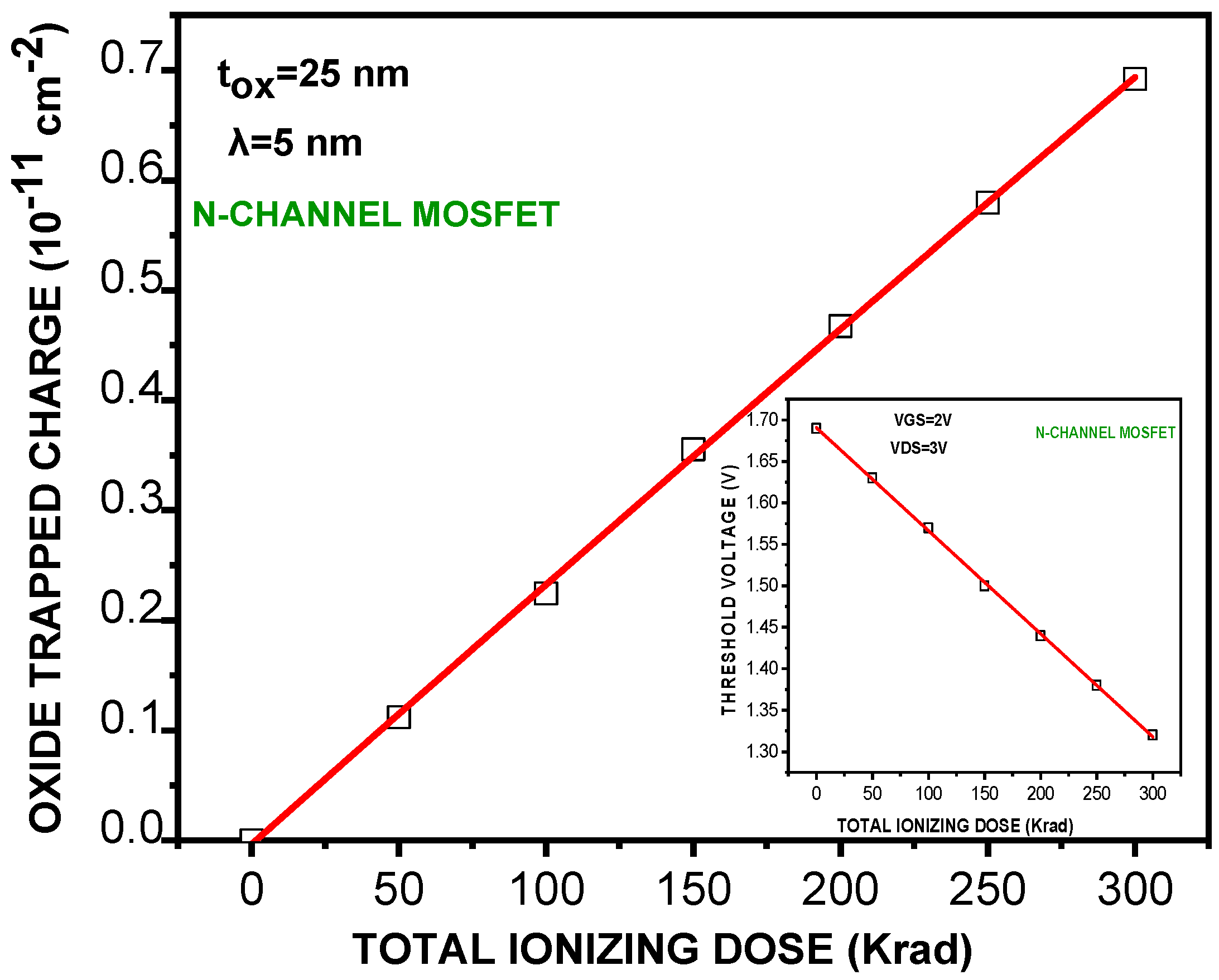
Figure 1. Evolution of oxide trapped charge density and threshold voltage value of an n-MOSFET (L = 1 µm, W = 24 µm, tox = 25 nm) with increasing total ionizing dose (60Co γ source).
Micromachines 16 01064 g001
Figure 2. Transconductance (gm) as a function of TID for an n-MOSFET (L = 1 µm, W = 24 µm). Data were extracted at saturation regime with VDS = 3 V following different total dose levels.
Micromachines 16 01064 g002
Figure 3. Drain conductance gd versus TID for an n-MOSFET under increasing irradiation. Experimental points are shown with polynomial fitting (Equation (12)).
Micromachines 16 01064 g003
Figure 4. Schematic of a basic current mirror based on two nchannel CMOS transistors, NMOSFET1 (diode connected) and NMOSFET2.
Micromachines 16 01064 g004
Figure 5. Current gain of a simple current mirror (SCM) as a function of dissymmetry percentage (x) at different TID levels. The gain decreases as TID increases, highlighting reduced current replication accuracy due to radiation−induced oxide charge trapping.
Micromachines 16 01064 g005
Figure 6. Input impedance of the SCM as a function of dissymmetry percentage under different TID doses. A positive correlation is observed, with both higher dissymmetry and larger TID contributing to increased input impedance.
Micromachines 16 01064 g006
Figure 7. Output impedance of the SCM as a function of dissymmetry percentage under different TID doses. In contrast to the input impedance, the output impedance decreases with higher asymmetry and TID, reducing the ability of the current mirror to drive loads effectively.
Micromachines 16 01064 g007
Table 1. TID−induced degradation in n−MOSFET current mirrors.
TID Dose (krad(Si))Threshold Voltage Vth (V)Transconductance gm (µS)
01.691.099
501.631.16
1001.571.24
1501.501.28
2001.441.32
2501.381.38
3001.321.40
Table 2. Comparative summary of TID−induced threshold voltage and transconductance changes in n−MOSFETs and related devices.
Study/ReferenceDevice TypeTID Range (krad(Si))Observed ΔVth (V)Observed gm ChangeNotes/Key Findings
This workn−MOSFET current mirror, SOI, L = 1 µm, W = 24 µm50–300−0.37 (1.69 → 1.32)+27% (1.099 → 1.40 µS)Charge trapping in oxide, TID−induced degradation of current mirror accuracy
Cao et al., 2022 [2]n−MOSFET0–300−0.3 approx.+20%Combined TID and electrical stress effects studied
Gao et al., 2023 [3]CMOS inverter0–150−0.15+10%Simulation study of TID effects in inverter circuits
Bonaldo, 2022
[4]
GAA Si nanowire CMOS0–500−0.4+25%Ultra−high TID, highly scaled devices, significant ΔVth observed
Dubois et al., 2023 [7]FDSOI 22 nm0–200−0.12+8%Modeling TID effects
Disclaimer/Publisher’s Note: The statements, opinions and data contained in all publications are solely those of the individual author(s) and contributor(s) and not of MDPI and/or the editor(s). MDPI and/or the editor(s) disclaim responsibility for any injury to people or property resulting from any ideas, methods, instructions or products referred to in the content.