
Composite Compensation Method for Scale-Factor Nonlinearity in MEMS Gyroscopes Based on Initial Calibration

Abstract
1. Introduction
2. Mechanical Structure of MEMS Gyroscopes
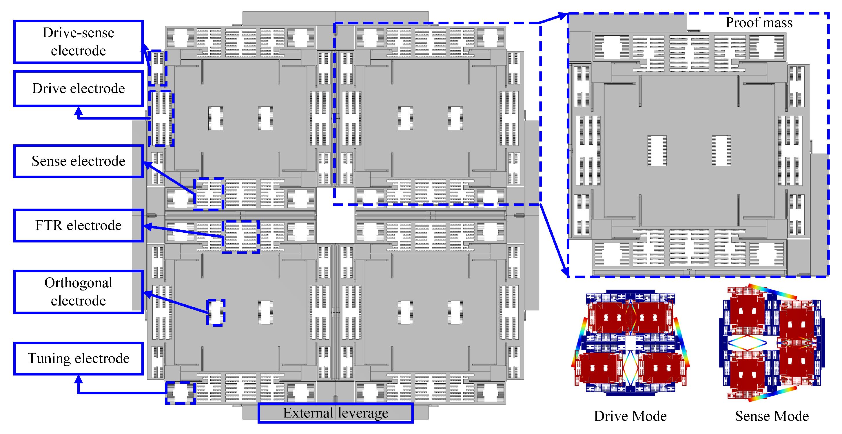
2.1. Mechanical Structure of the QMG
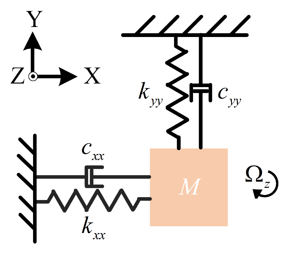
2.2. Dynamic Model
3. Analysis of Closed-Loop Scale-Factor Nonlinearity Mechanism
3.1. Analysis of Nonlinearity Induced by Drive Frequency
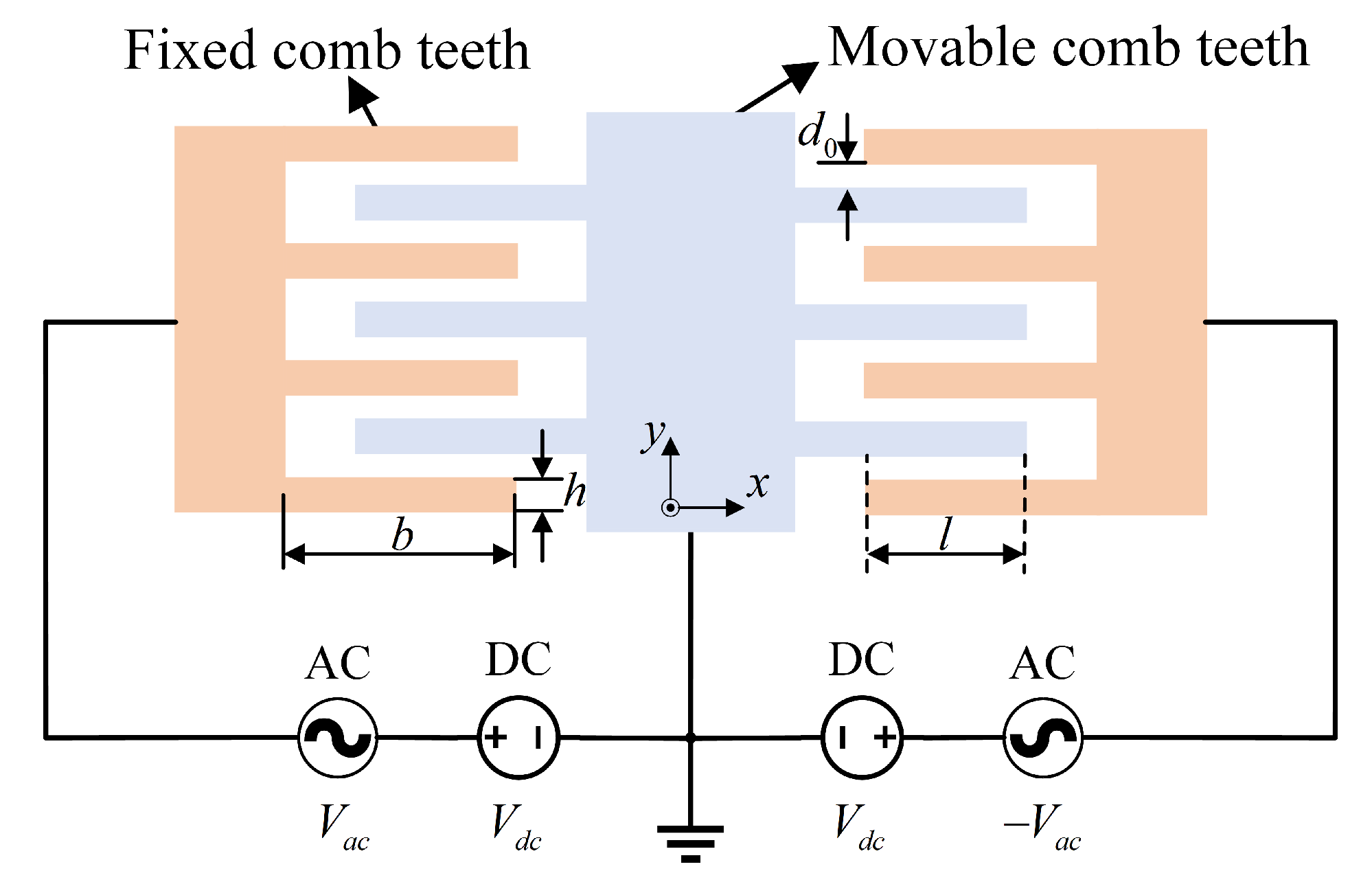
3.2. Analysis of Nonlinearity Introduced by the Sensing Force-Feedback Comb Electrode
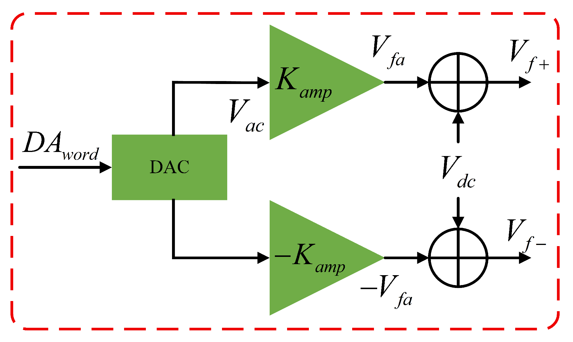
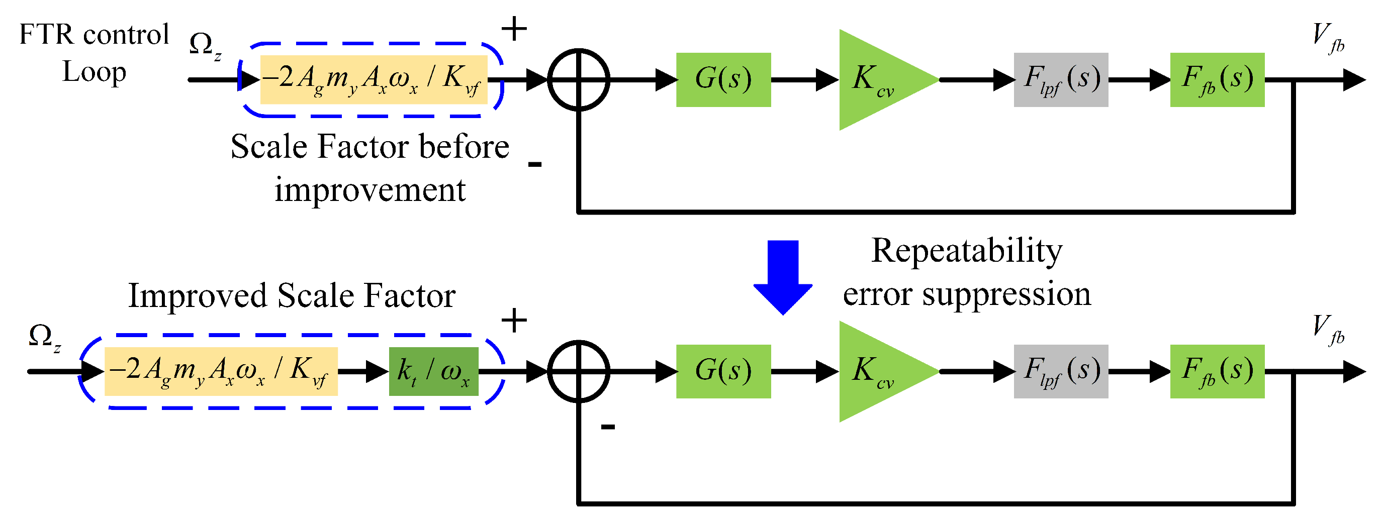
3.3. Analysis of Nonlinearity Introduced by the Force-Feedback Voltage-Generation Circuit
4. Composite Compensation Method with Initial Calibration
4.1. Initial Calibration Method for Scale Factor
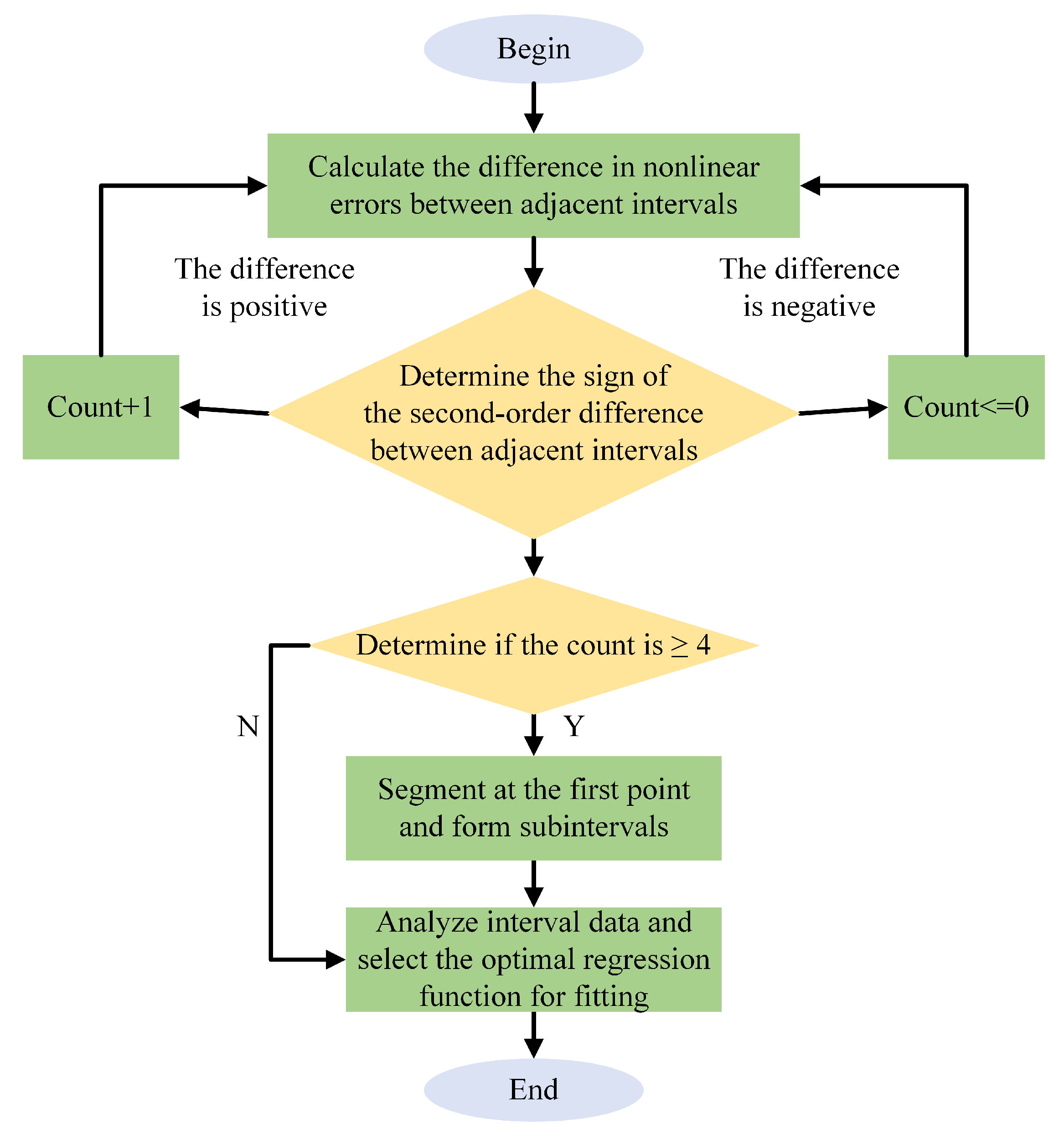
4.2. Piecewise Scale-Factor Nonlinearity Compensation Method
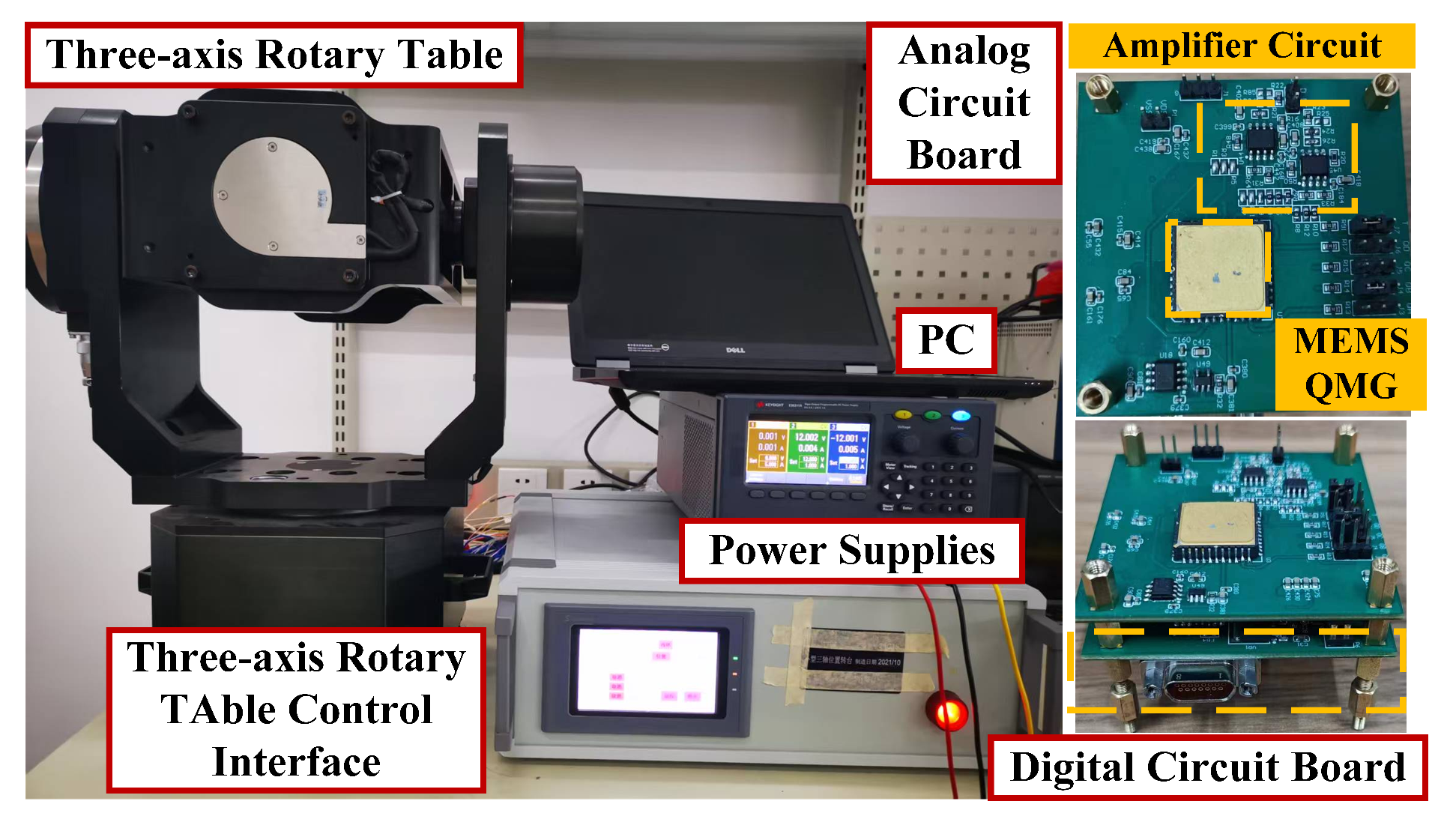
5. Experimental Verification
6. Conclusions
Author Contributions
Funding
Data Availability Statement
Conflicts of Interest
References
- Wang, S.R. Research Status and Advances in Micro-Inertial Instrument Technology. Mech. Manuf. Autom. 2011, 40, 6–12. [Google Scholar]
- Zhou, B. Research Status and Development Trends of Silicon Micromechanical Gyroscopes. In Proceedings of the 2003 Inertial Technology Symposium for Scientists and Engineers; Chinese Society of Inertial Technology: Nanjing, China, 2003; pp. 100–102. [Google Scholar]
- Greiff, P.; Boxenhorn, B.; King, T.; Niles, L. Silicon Monolithic Micromechanical Gyroscope. In Proceedings of the International Conference on Solid-State Sensors & Actuators, San Francisco, CA, USA, 24–27 June 1991. [Google Scholar]
- Huang, Y.X.; Shi, Z.K.; Li, L.; Ma, Y.; Zhao, Q.; Zhang, Z. Optimal Design for Improving Dynamic Characteristics of Force-Feedback Rate Gyroscopes. Chin. J. Sens. Actuat. 2005, 18, 856–859. [Google Scholar]
- Xie, J.W. Nonlinear Dynamics and Detection Performance of Tapered Beam Microgyroscopes. Master’s Thesis, Tianjin University of Technology, Tianjin, China, 2023. [Google Scholar]
- Wang, P.; Li, Q.; Xu, Y.; Zhang, Y.; Xi, X.; Wu, Y.; Wu, X.; Xiao, D. Calibration of Coupling Errors for Scale Factor Nonlinearity Improvement in Navigation-Grade Honeycomb Disk Resonator Gyroscope. IEEE Trans. Ind. Electron. 2023, 70, 5347–5355. [Google Scholar] [CrossRef]
- Prikhodko, I.P.; Trusov, A.A.; Shkel, A.M. Compensation of Drifts in High-Q MEMS Gyroscopes Using Temperature Self-Sensing. Sens. Actuators A Phys. 2013, 201, 517–524. [Google Scholar] [CrossRef]
- Chikovani, V.V.; Petrenko, O.V. Vibratory Gyroscope Scale Factor Multi-Parametric Calibration. In Proceedings of the IEEE International Conference on Methods & Systems of Navigation & Motion Control, Kiev, Ukraine, 14–17 October 2014; pp. 129–131. [Google Scholar]
- Aktakka, E.E.; Woo, J.K.; Najafi, K. On-Chip Characterization of Scale-Factor of a MEMS Gyroscope via a Micro Calibration Platform. In Proceedings of the IEEE International Symposium on Inertial Sensors & Systems, Kauai, HI, USA, 27–30 March 2017. [Google Scholar]
- Norouzpour-Shirazi, A.; Ayazi, F. A Dual-Mode Actuation and Sensing Scheme for In-Run Calibration of Bias and Scale Factor Errors in Axisymmetric Resonant Gyroscopes. IEEE Sens. J. 2017, 18, 1993–2005. [Google Scholar] [CrossRef]
- Vatanparvar, D.; Asadian, M.H.; Askari, S.; Shkel, A.M. Characterization of Scale Factor Nonlinearities in Coriolis Vibratory Gyroscopes. In Proceedings of the 2019 IEEE International Symposium on Inertial Sensors and Systems (INERTIAL), Naples, FL, USA, 1–5 April 2019; pp. 1–4. [Google Scholar]
- Liu, C.Z.; Wang, X.J.; Tang, Q.J. Error Analysis and Compensation Research of Scale Factor for MEMS Gyroscope. In Proceedings of the International Symposium on Optoelectronic Technology & Application: Image Processing & Pattern Recognition, Beijing, China, 13–15 May 2014. [Google Scholar]
- Wu, L.F.; Zhang, F.X.; Peng, Z.H. Research on Fast Calibration Method for Scale Factor of Micro Machined Gyroscope. In Proceedings of the 2008 3rd IEEE Conference on Industrial Electronics and Applications, Singapore, 3–5 June 2008; pp. 1082–1085. [Google Scholar]
- Jianli, L.; Min, D. Fuzzy Modeling and Compensation of Scale Factor for MEMS Gyroscope. In Proceedings of the 2010 International Conference on Digital Manufacturing & Automation, Changsha, China, 18–20 December 2010; pp. 766–771. [Google Scholar]
- Cui, J.; Yan, G.; Zhao, Q. Enhanced Temperature Stability of Scale Factor in MEMS Gyroscope Based on Multi-Parameters Fusion Compensation Method. Measurement 2019, 148, 106947. [Google Scholar] [CrossRef]
- Wang, M.; Cao, H.; Shen, C.; Chai, J. A Novel Self-Calibration Method and Experiment of MEMS Gyroscope Based on Virtual Coriolis Force. Micromachines 2018, 9, 328. [Google Scholar] [CrossRef] [PubMed]
- Zhang, J.; He, C.; Liu, Y.; Liu, D.; Zhao, Q.; Yang, Z.; Yan, G. A Novel Scale Factor Calibration Method for a MEMS Gyroscope Based on Virtual Coriolis Force. In Proceedings of the 10th IEEE International Conference on Nano/Micro Engineered and Molecular Systems, Xi’an, China, 7–11 April 2015; pp. 58–62. [Google Scholar]
- Zhou, R.; Cui, R.; Shen, C.; Shi, Y.; Yu, J.; Ren, Y.; Cao, H. A Self-Test Method for MEMS Gyroscope With Equivalent Inertial Force. IEEE Trans. Instrum. Meas. 2025, 74, 9517010. [Google Scholar] [CrossRef]
- Aktakka, E.E.; Woo, J.K.; Egert, D.; Gordenker, R.J.; Najafi, K. A Microactuation and Sensing Platform with Active Lockdown for In Situ Calibration of Scale Factor Drifts in Dual-Axis Gyroscopes. IEEE/ASME Trans. Mechatronics 2015, 20, 934–943. [Google Scholar] [CrossRef]
- Chen, Y.; Aktakka, E.E.; Woo, J.K.; Najafi, K.; Oldham, K.R. On-Chip Capacitive Sensing and Tilting Motion Estimation of a Micro-Stage for In Situ MEMS Gyroscope Calibration. Mechatronics 2018, 56, 242–253. [Google Scholar] [CrossRef]
- Gadola, M.; Buffoli, A.; Sansa, M.; Berthelot, A.; Robert, P.; Langfelder, G. 1.3 mm2 Nav-Grade NEMS-Based Gyroscope. J. Microelectromech. Syst. 2021, 30, 513–520. [Google Scholar] [CrossRef]
- Li, C.; Wen, H.; Chen, H.; Ayazi, F. A Digital Force-to-Rebalance Scheme for High-Frequency Bulk-Acoustic-Wave Micro-Gyroscopes. Sens. Actuators A Phys. 2020, 313, 112181. [Google Scholar] [CrossRef]
- Nitzan, S.; Ahn, C.H.; Su, T.H.; Li, M.; Ng, E.J.; Wang, S.; Yang, Z.M.; O’Brien, G.; Boser, B.E.; Kenny, T.W.; et al. Epitaxially Encapsulated Polysilicon Disk Resonator Gyroscope. In Proceedings of the IEEE International Conference on MicroElectro Mechanical Systems, Taipei, Taiwan, 20–24 January 2013; pp. 625–628. [Google Scholar]
- Zhou, Y.; Ren, J.B.; Liu, M.; Zhou, T.; Su, Y. An In-Run Automatic Mode-Matching Method for N = 3 MEMS Disk Resonator Gyroscope. IEEE Sens. J. 2021, 21, 27601–27611. [Google Scholar] [CrossRef]

| Parameters | Value |
|---|---|
| Mass | 1.56 mg |
| Frequency (X) | 4634 Hz |
| Frequency (Y) | 4711 Hz |
| Quality factor (X) | |
| Quality factor (Y) | |
| Initial frequency split | 77 Hz |
| Velocity to current factor (X) | A/m/s |
| Voltage to force factor (X) | N/V |
| Velocity to current factor (Y) | A/m/s |
| Voltage to force factor (Y) | N/V |
| Input Rate (°/s) | /V | |
|---|---|---|
| −200 | 29E345 | 1.637 |
| −100 | 14F191 | 0.816 |
| −50 | A78B6 | 0.408 |
| −20 | 43,033 | 0.163 |
| −10 | 21,808 | 0.0815 |
| −5 | 10BF2 | 0.0407 |
| −2 | 6B19 | 0.0163 |
| −1 | 357B | 0.00816 |
| −0.5 | 1AAB | 0.00408 |
| −0.2 | A95 | 0.00163 |
| −0.1 | 539 | 0.0008217 |
| 0.1 | FFA81 | −0.000809 |
| 0.2 | FFF524 | −0.00162 |
| 0.5 | FFE50E | −0.00407 |
| 1 | FFCAF3 | −0.00815 |
| 2 | FF94A1 | −0.0163 |
| 5 | FEF3C7 | −0.0408 |
| 10 | FDE7B1 | −0.0816 |
| 20 | FBC786 | −0.163 |
| 50 | F58F03 | −0.408 |
| 100 | EB0E29 | −0.816 |
| 200 | D61C74 | −1.637 |
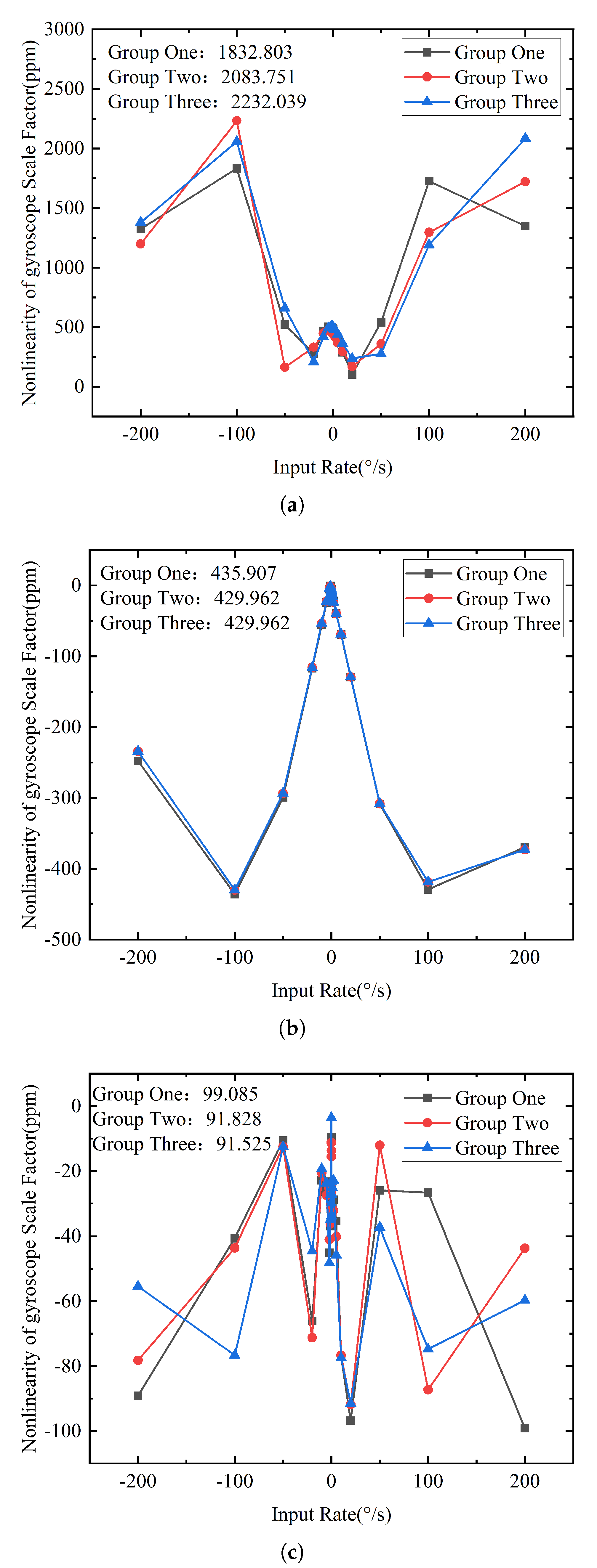
| Group | Origin | Tra Method | This Work |
|---|---|---|---|
| One (ppm) | 1832.803 | 435.907 | 99.085 |
| Two (ppm) | 2083.751 | 429.962 | 91.828 |
| Three (ppm) | 2232.039 | 429.962 | 91.525 |
| SF (LSB/°/s) | 13,709.853 | −13,694.696 | 13,719.534 |
| Repetitive error (ppm) | 1230.656 | 163.253 | 93.534 |
Disclaimer/Publisher’s Note: The statements, opinions and data contained in all publications are solely those of the individual author(s) and contributor(s) and not of MDPI and/or the editor(s). MDPI and/or the editor(s) disclaim responsibility for any injury to people or property resulting from any ideas, methods, instructions or products referred to in the content. |
© 2025 by the authors. Licensee MDPI, Basel, Switzerland. This article is an open access article distributed under the terms and conditions of the Creative Commons Attribution (CC BY) license (https://creativecommons.org/licenses/by/4.0/).
Share and Cite
Ding, Z.; Zhou, Y. Composite Compensation Method for Scale-Factor Nonlinearity in MEMS Gyroscopes Based on Initial Calibration. Micromachines 2025, 16, 851. https://doi.org/10.3390/mi16080851
Ding Z, Zhou Y. Composite Compensation Method for Scale-Factor Nonlinearity in MEMS Gyroscopes Based on Initial Calibration. Micromachines. 2025; 16(8):851. https://doi.org/10.3390/mi16080851
Chicago/Turabian StyleDing, Zhaoyin, and Yi Zhou. 2025. "Composite Compensation Method for Scale-Factor Nonlinearity in MEMS Gyroscopes Based on Initial Calibration" Micromachines 16, no. 8: 851. https://doi.org/10.3390/mi16080851
APA StyleDing, Z., & Zhou, Y. (2025). Composite Compensation Method for Scale-Factor Nonlinearity in MEMS Gyroscopes Based on Initial Calibration. Micromachines, 16(8), 851. https://doi.org/10.3390/mi16080851