
Structural Optimization Design of the Dual-Layer CMUT with Low Power Consumption and High Ultrasonic Reception Performance

 ,
,  ,
, 


Abstract
1. Introduction
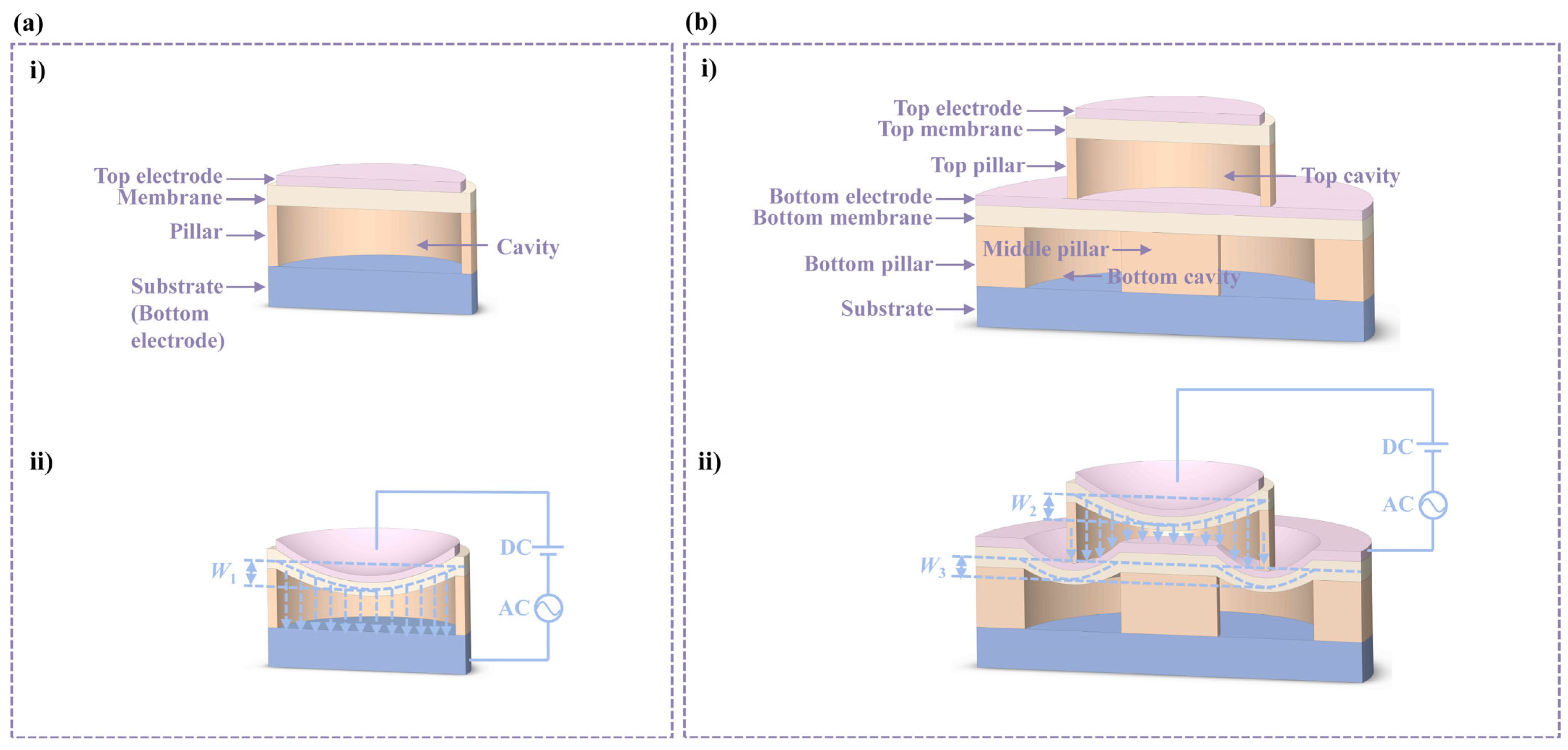
2. Design and Concept of D-CMUT
3. Results
3.1. Collapse Voltage
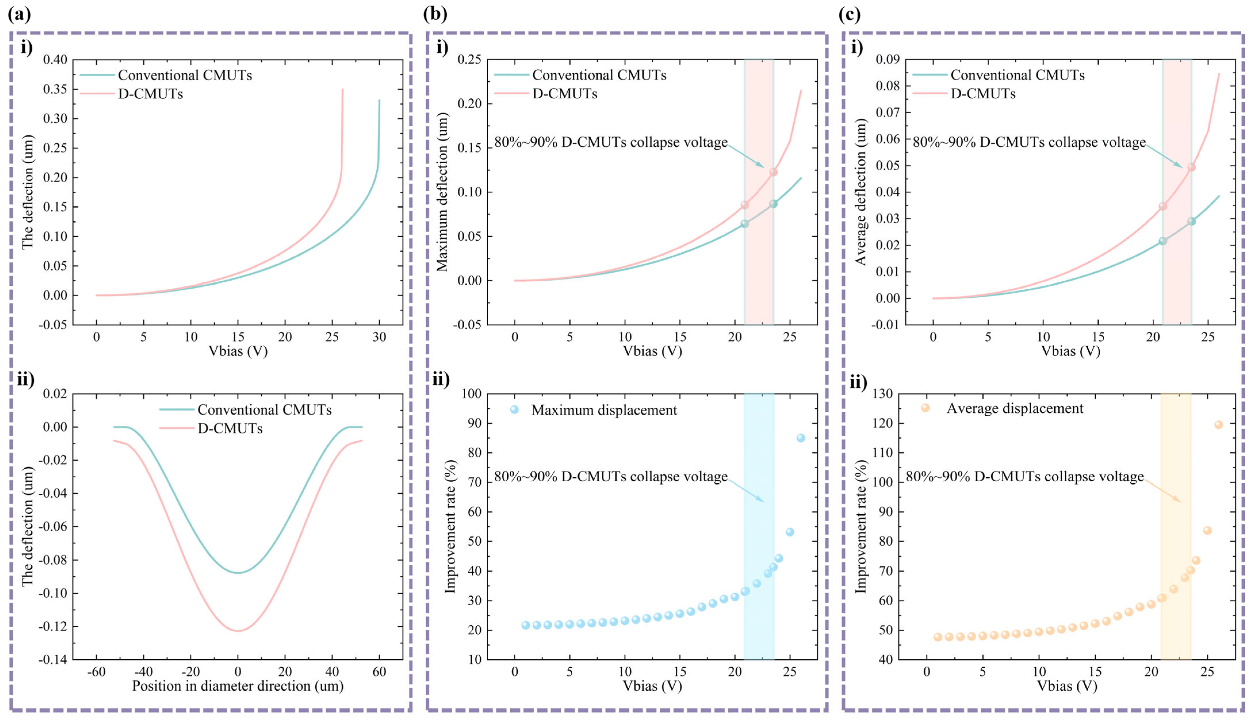
3.2. Membrane Deflection
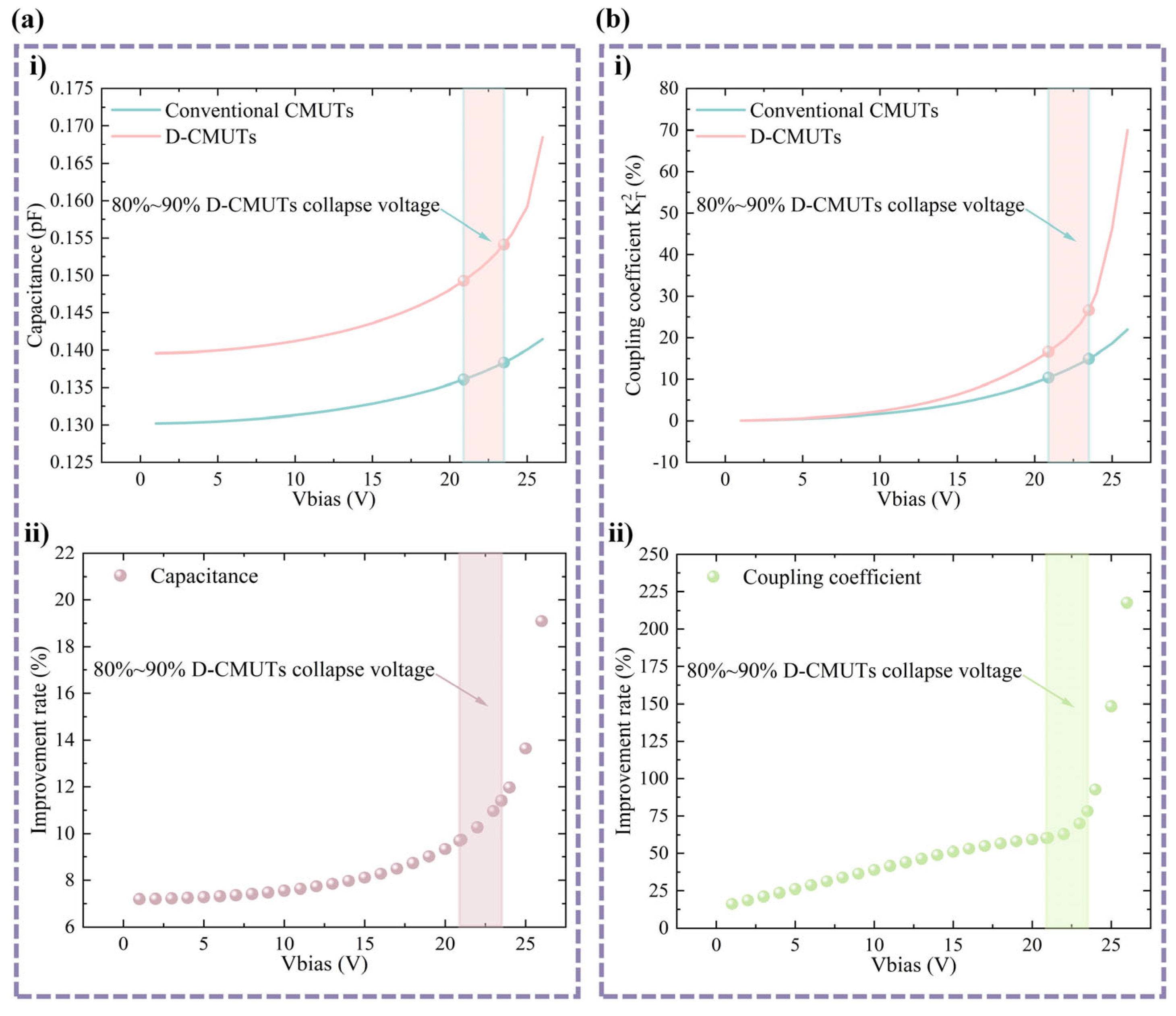
3.3. Electromechanical Coupling Coefficient
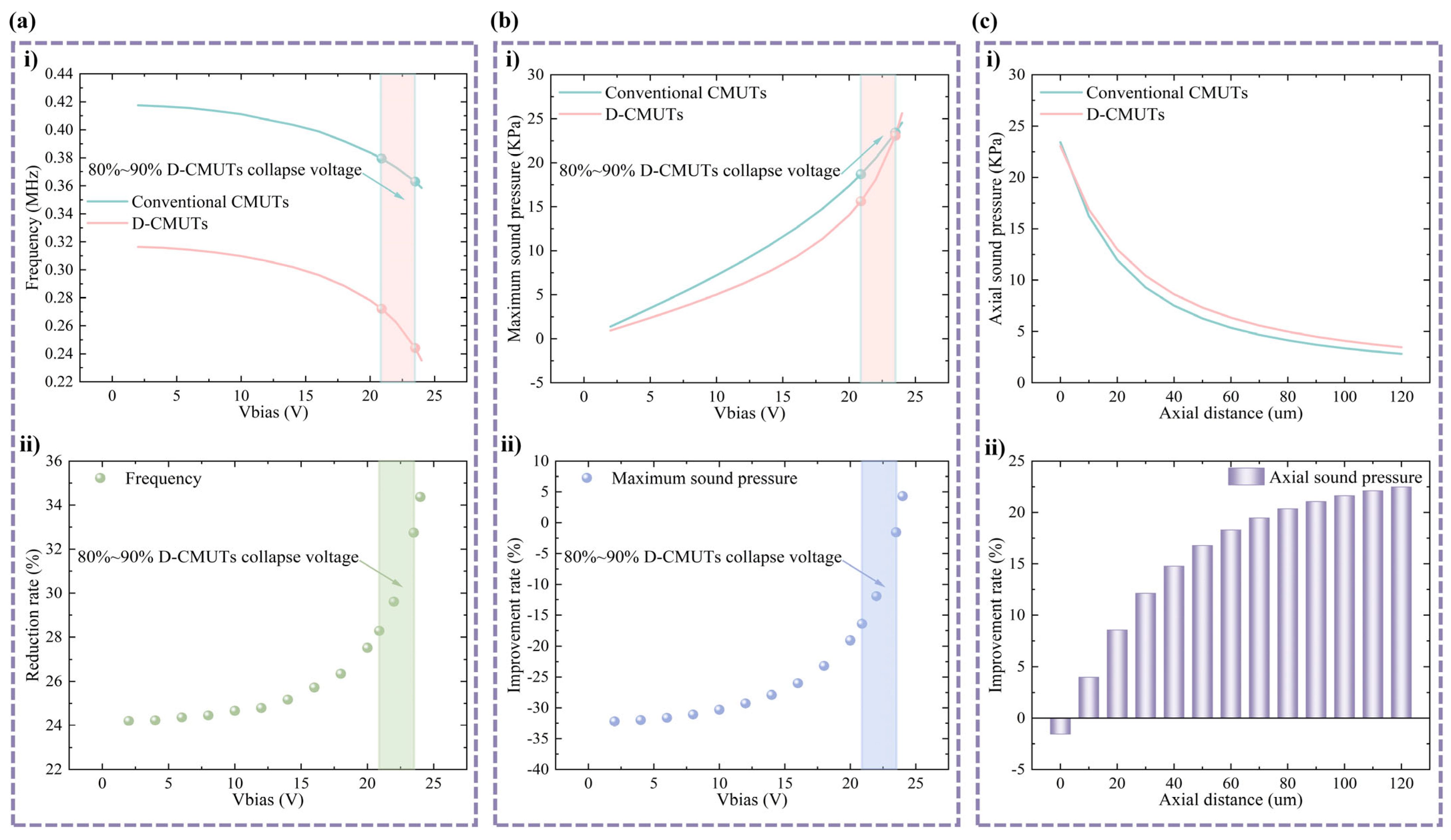
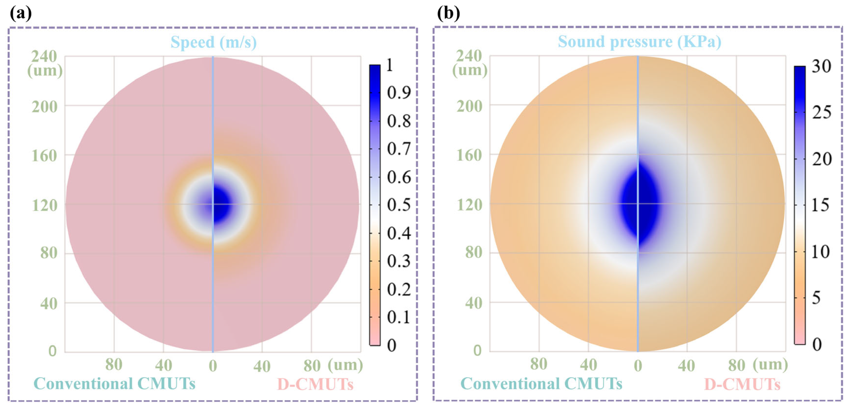
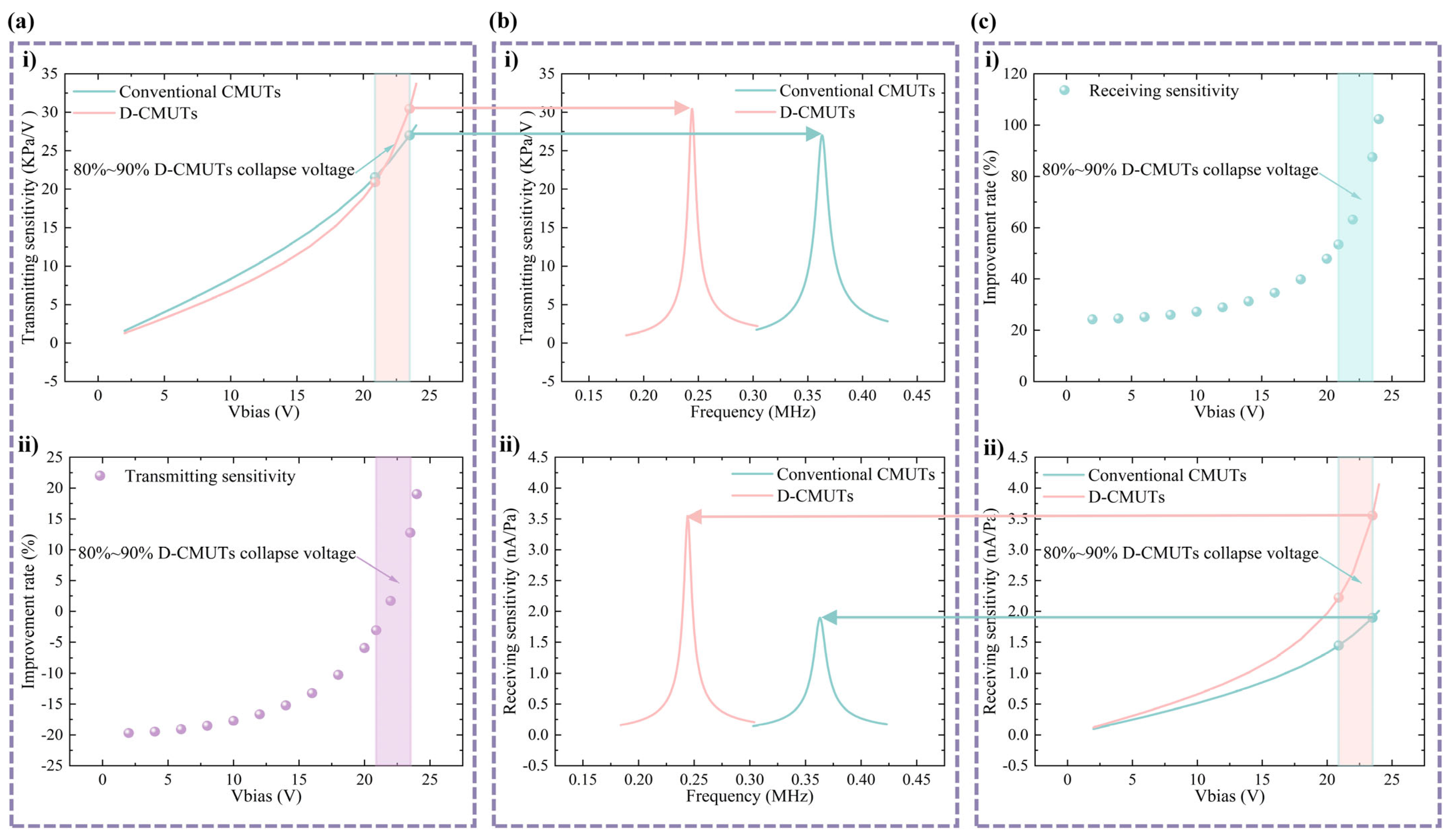
3.4. Ultrasonic Transmitting and Receiving Performances
4. Structural Optimization Design and Discussion
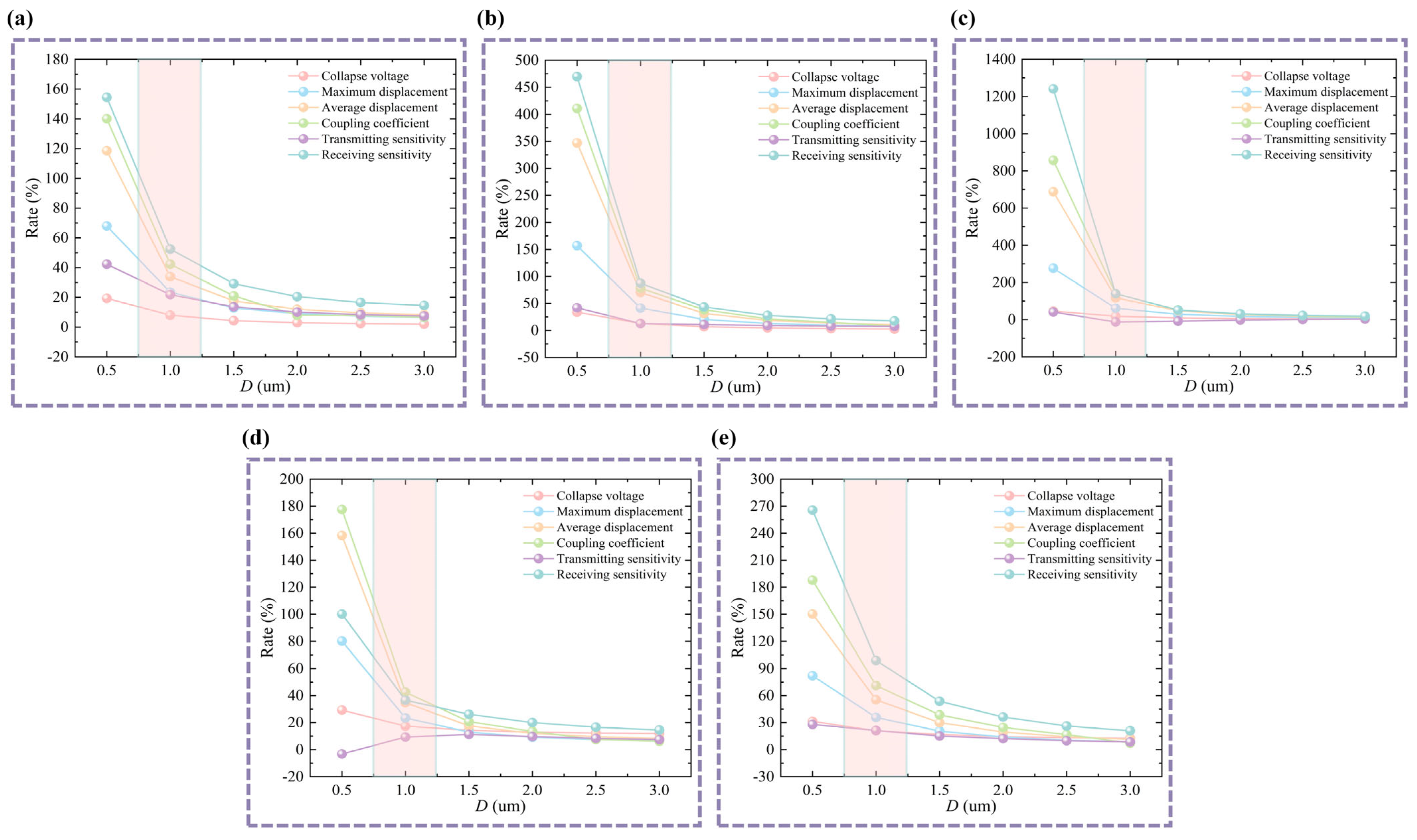
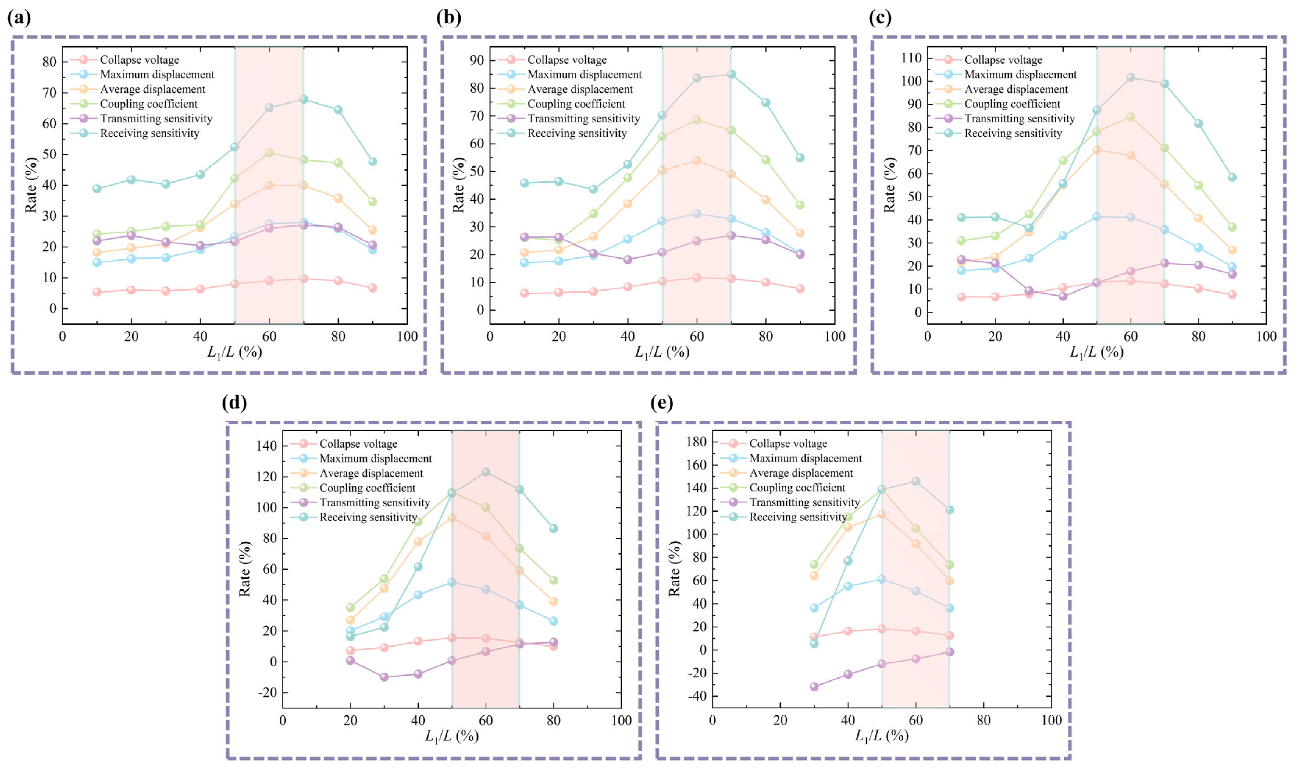
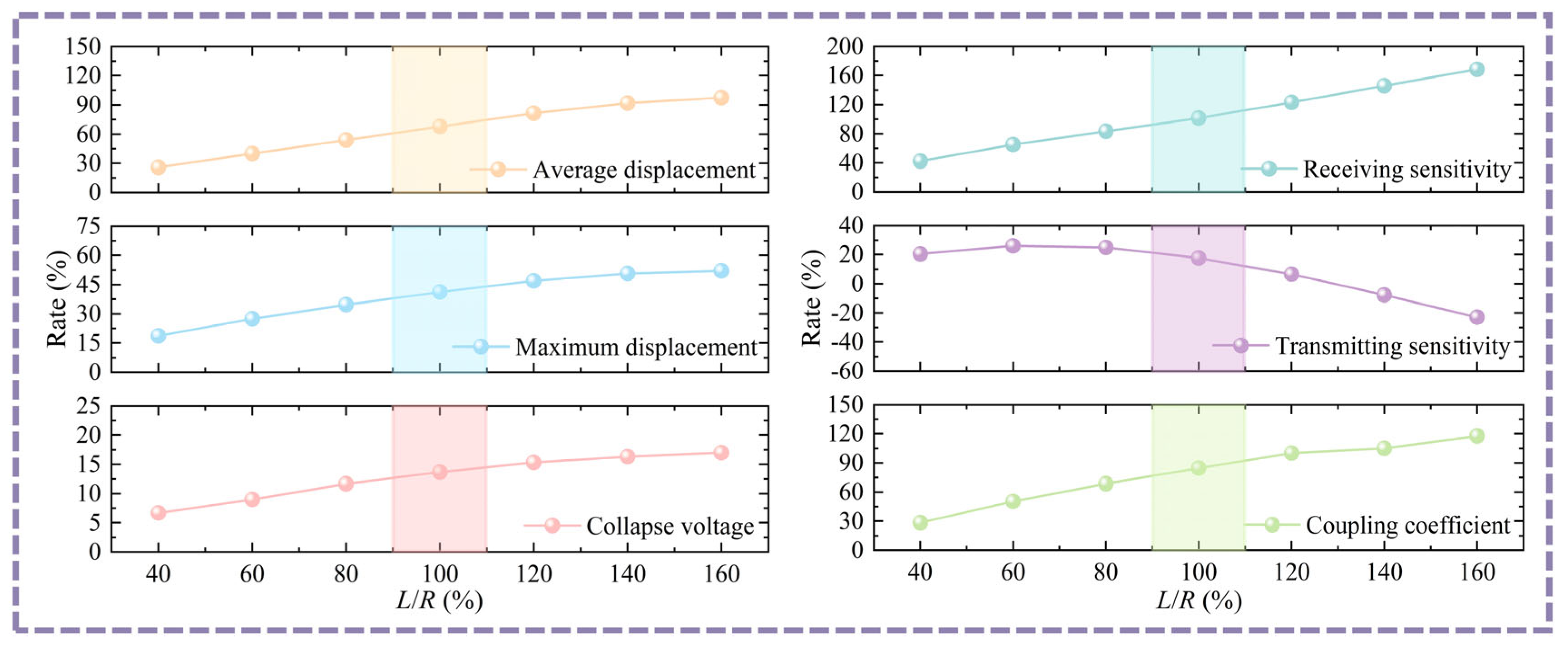
4.1. Structural Optimization Design
4.2. Discussion
5. Conclusions
Author Contributions
Funding
Data Availability Statement
Conflicts of Interest
References
- Peng, C.; Cai, Q.; Chen, M.; Jiang, X. Recent Advances in Tracking Devices for Biomedical Ultrasound Imaging Applications. Micromachines 2022, 13, 1855. [Google Scholar] [CrossRef] [PubMed]
- Zhang, Z.; Liu, R.; Li, G.; Su, M.; Li, F.; Zheng, H.; Qiu, W. A Dual-Mode 2D Matrix Array for Ultrasound Image-Guided Noninvasive Therapy. IEEE Trans. Biomed. Eng. 2021, 68, 3482–3490. [Google Scholar] [CrossRef] [PubMed]
- Li, Z.; Li, J.; Zhao, Y.; Li, Z.; Shi, X.; Qin, S.; Li, J.; Yuan, J.; Ma, Q.; Zhao, Z.; et al. Noninvasive Stress Detection Based on Piezoelectric Micromachined Ultrasonic Transducers for Bolt Loosening Warning. IEEE Trans. Instrum. Meas. 2024, 73, 9509116. [Google Scholar] [CrossRef]
- Choi, W.Y.; Kwak, Y.S.; Park, K.K. Fingerprint Imaging System Based on Capacitive Micromachined Ultrasonic Transducer by Using Impediography Method Including Direct Touch and Waveguide Methods. IEEE Trans. Ultrason. Ferroelectr. Freq. Control 2018, 66, 402–411. [Google Scholar] [CrossRef]
- Lian, Y.; Lu, Z.; Huang, X.; Shangguan, Q.; Yao, L.; Huang, J.; Liu, Z. A Transfer Learning Strategy for Cross-Subject and Cross-Time Hand Gesture Recognition Based on A-Mode Ultrasound. IEEE Sens. J. 2024, 24, 17183–17192. [Google Scholar] [CrossRef]
- Liu, Y.; Fan, Y.; Wu, Z.; Yao, J.; Long, Z. Ultrasound-based 3-D gesture recognition: Signal optimization, trajectory, and feature classification. IEEE Trans. Instrum. Meas. 2023, 72, 9503012. [Google Scholar] [CrossRef]
- Miao, J.; Shen, W.; He, C.; Xue, C.; Xiong, J. Micro-electro-mechanical systems capacitive ultrasonic transducer with a higher electromechanical coupling coefficient. Micro Nano Lett. 2015, 10, 541–544. [Google Scholar] [CrossRef]
- Khuri-Yakub, B.T.; Oralkan, Ö. Capacitive micromachined ultrasonic transducers for medical imaging and therapy. J. Micromech. Microeng. 2011, 21, 054004. [Google Scholar] [CrossRef]
- Brenner, K.; Ergun, A.S.; Firouzi, K.; Rasmussen, M.F.; Stedman, Q.; Khuri-Yakub, B.P. Advances in Capacitive Micromachined Ultrasonic Transducers. Micromachines 2019, 10, 152. [Google Scholar] [CrossRef]
- Helmerich, J.; Wich, M.; Hofmann, A.; Schaechtle, T.; Rupitsch, S.J. Multiple Ring Electrode-Based PMUT with Tunable Deflections. Micromachines 2025, 16, 623. [Google Scholar] [CrossRef]
- Zhang, H.; Liang, D.; Wang, Z.; Ye, L.; Rui, X.; Zhang, X. Fabrication and Characterization of a Wideband Low-Frequency CMUT Array for Air-Coupled Imaging. IEEE Sens. J. 2020, 20, 14090–14100. [Google Scholar] [CrossRef]
- Lu, W.; Ma, G.; Liu, C.; Wang, R.; Zhang, G.; Zhang, W.; Yilmaz, M.; Zhang, S. Developing 3D-CMUT for Ultrasonic Guided Wave-Based Damage Imaging Applications: A Comprehensive Theory and Simulation Study. IEEE Sens. J. 2024, 24, 40494–40506. [Google Scholar] [CrossRef]
- Zhao, L.; Zhao, Y.; Xia, Y.; Li, Z.; Li, J.; Zhang, J.; Wang, J.; Zhou, X.; Li, Y.; Zhao, Y.; et al. A Novel CMUT-Based Resonant Biochemical Sensor Using Electrospinning Technology. IEEE Trans. Ind. Electron. 2018, 66, 7356–7365. [Google Scholar] [CrossRef]
- Pelenis, D.; Barauskas, D.; Sapeliauskas, E.; Vanagas, G.; Mikolajunas, M.; Virzonis, D. Acoustical Streaming in Microfluidic CMUT Integrated Chip Controls the Biochemical Interaction Rate. J. Microelectromech. Syst. 2017, 26, 1012–1017. [Google Scholar] [CrossRef]
- Sanders, J.L.; Biliroglu, A.O.; Newsome, I.G.; Adelegan, O.J.; Yamaner, F.Y.; Dayton, P.A.; Oralkan, O. A Handheld Imaging Probe for Acoustic Angiography with an Ultrawideband Capacitive Micromachined Ultrasonic Transducer (CMUT) Array. IEEE Trans. Ultrason. Ferroelectr. Freq. Control 2022, 69, 2318–2330. [Google Scholar] [CrossRef]
- Pei, Y.; Zhang, Y.; Hu, S.; Wang, Z.; Li, Y.; He, C.; Zhang, S.; Wang, R.; Zhang, W.; Zhang, G. Breast Transmission Ultrasound Tomography Based on Capacitive Micromachined Ultrasonic Transducer Linear Arrays. IEEE Sens. J. 2021, 22, 1209–1217. [Google Scholar] [CrossRef]
- Joseph, J.; Ma, B.; Khuri-Yakub, B.T. Applications of Capacitive Micromachined Ultrasonic Transducers: A Comprehensive Review. IEEE Trans. Ultrason. Ferroelectr. Freq. Control 2021, 69, 456–467. [Google Scholar] [CrossRef]
- Ma, B.; Firouzi, K.; Brenner, K.; Khuri-Yakub, B.T. Wide Bandwidth and Low Driving Voltage Vented CMUTs for Airborne Applications. IEEE Trans. Ultrason. Ferroelectr. Freq. Control 2019, 66, 1777–1785. [Google Scholar] [CrossRef]
- Yaralioglu, G.; Ergun, A.; Bayram, B.; Haeggstrom, E.; Khuri-Yakub, B. Calculation and measurement of electromechanical coupling coefficient of capacitive micromachined ultrasonic transducers. IEEE Trans. Ultrason. Ferroelectr. Freq. Control 2003, 50, 449–456. [Google Scholar] [CrossRef]
- Kshirsagar, A.; Sampaleanu, A.; Chee, R.; Moussa, W.; Zemp, R.J. Pre-Charged CMUTs with Efficient Low-Bias Voltage Operation for Medical Applications. In Proceedings of the 2013 IEEE International Ultrasonics Symposium (IUS), Prague, Czech Republi, 21–25 July 2013; pp. 1728–1730. [Google Scholar]
- Seok, C.; Mahmud, M.M.; Adelegan, O.; Zhang, X.; Oralkan, O. A battery-operated wireless multichannel gas sensor system based on a capacitive micromachined ultrasonic transducer (CMUT) array. In Proceedings of the 2016 IEEE Sensors, Orlando, FL, USA, 30 October–3 November 2016; pp. 1–3. [Google Scholar]
- Bang, S.; Oh, C.; Lee, S.-M.; Kim, S.; Lee, T.; Nam, S.; Jung, J.; Lee, H.J. Fabrication of Capacitive Micromachined Ultrasonic Transducers with High-k Insulation Layer Using Silicon Fusion Bonding. J. Microelectromech. Syst. 2024, 34, 65–72. [Google Scholar] [CrossRef]
- Goel, C.; Cicek, P.-V.; Robichaud, A. Design and Implementation of Low-Voltage Tunable Capacitive Micro-Machined Transducers (CMUT) for Portable Applications. Micromachines 2022, 13, 1598. [Google Scholar] [CrossRef] [PubMed]
- Sherman, C.H.; Butler, J.L. Transducers and Arrays for Underwater Sound; Springer: New York, NY, USA, 2007. [Google Scholar]
- Huang, Y.; Zhuang, X.; Haeggstrom, E.O.; Ergun, A.S.; Cheng, C.-H.; Khuri-Yakub, B.T. Capacitive micromachined ultrasonic transducers with piston-shaped membranes: Fabrication and experimental characterization. IEEE Trans. Ultrason. Ferroelectr. Freq. Control 2009, 56, 136–145. [Google Scholar] [CrossRef] [PubMed]
- Guldiken, R.O.; Zahorian, J.; Yamaner, F.Y.; Degertekin, F.L. Dual-electrode CMUT with non-uniform membranes for high electromechanical coupling coefficient and high bandwidth operation. IEEE Trans. Ultrason. Ferroelectr. Freq. Control 2009, 56, 1270–1276. [Google Scholar] [CrossRef]
- Kim, D.K.; Chung, S.-W.; Jeong, B.-G.; Hong, S.-W.; Shin, H. An indirectly clamped capacitive micromachined ultrasonic transducer with a high electromechanical coupling factor. Sens. Actuators A Phys. 2013, 203, 82–91. [Google Scholar] [CrossRef]
- Na, S.; Chen, A.I.; Wong, L.L.; Li, Z.; Macecek, M.; Yeow, J.T. Capacitive micromachined ultrasonic transducers based on annular cell geometry for air-coupled applications. Ultrasonics 2016, 71, 152–160. [Google Scholar] [CrossRef]
- Li, Z.; Zhang, S.; Zhao, Y.; Qin, S.; Bai, S.; Yuan, J.; Li, J.; Li, Z.; Sun, B.; Ma, Q.; et al. Rational design of CMUTs with annular electrodes for high ultrasonic emission via ESSE enabled stiffness adjustment. Microelectron. Eng. 2024, 292, 112224. [Google Scholar] [CrossRef]
- Fraser, J.D.; Reynolds, P. Finite-element method for determination of electromechanical coupling coefficient for piezoelectric and capacitive micromachined ultrasonic transducers. J. Acoust. Soc. Am. 2000, 108, 2599. [Google Scholar] [CrossRef]
- Li, Z.; Zhao, L.; Li, J.; Zhao, Y.; Xu, T.; Luo, G.; Guo, S.; Liu, Z.; Jiang, Z. Analytical Expressions for the Electromechanical Coupling Coefficient of Capacitive Micromachined Ultrasonic Transducers (CMUTs) and Its Effects on Power Consumption. J. Mech. Eng. 2020, 56, 173–181. [Google Scholar]
- Li, Z.; Yuan, J.; Li, J.; Li, Z.; Zhao, Y.; Qin, S.; Ma, Q.; Shi, X.; Li, M.; Yuan, Z.; et al. Modeling and Optimization of CMUTs Arrays for Improved Transmission and Reception Performance in Immersion. IEEE Sens. J. 2024, 24, 7548–7563. [Google Scholar] [CrossRef]
- Vallet, M.; Varray, F.; Boutet, J.; Dinten, J.-M.; Caliano, G.; Savoia, A.S.; Vray, D. Quantitative comparison of PZT and CMUT probes for photoacoustic imaging: Experimental validation. Photoacoustics 2017, 8, 48–58. [Google Scholar] [CrossRef]


| Parameter | Value | Parameter | Value |
|---|---|---|---|
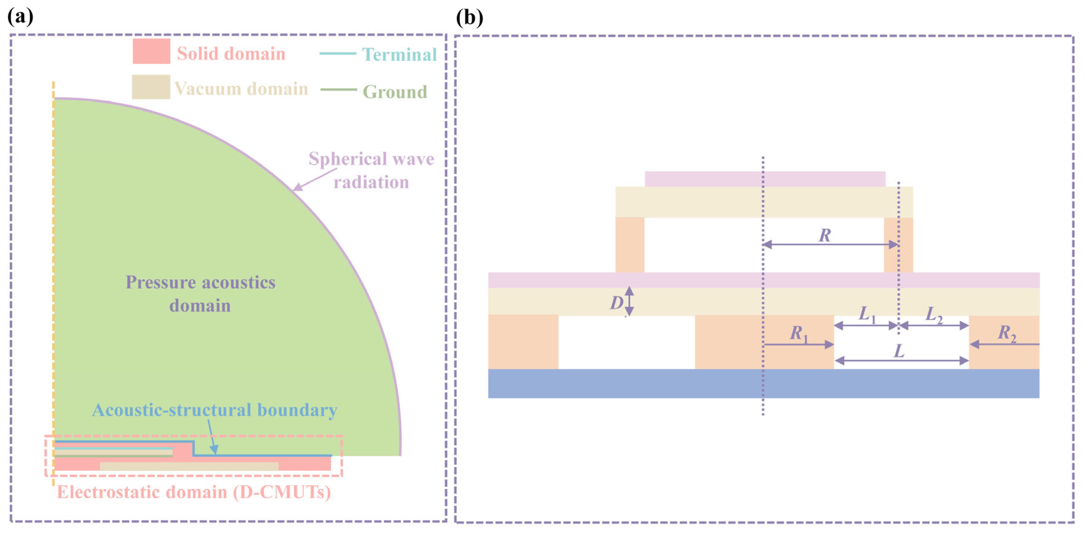
| Top Si membrane radius | 47.5 (µm) | Top Si membrane thickness | 1 (µm) |
| Bottom Si membrane radius | 75 (µm) | Bottom Si membrane thickness (D) | 1 (µm) |
| Si substrate radius | 100 (µm) | Si substrate thickness | 1 (µm) |
| Density of Si | 2332 kg/m3 | Poisson’s ratio of Si | 0.28 |
| Young’s modulus of Si | 130 GPa | Relative permittivity of Si | 11.7 |
| Top SiO2 pillar width | 5 (µm) | Top SiO2 pillar height | 0.5 (µm) |
| Bottom SiO2 pillar width (R2) | 25 (µm) | Bottom SiO2 pillar height | 0.5 (µm) |
| Middle SiO2 pillar radius (R1) | 25 (µm) | Middle SiO2 pillar height | 0.5 (µm) |
| Density of SiO2 | 2200 kg/m3 | Poisson’s ratio of SiO2 | 0.17 |
| Young’s modulus of SiO2 | 70 GPa | Relative permittivity of SiO2 | 4.2 |
| Top cavity radius | 47.5 (µm) | Top cavity height | 0.5 (µm) |
| Bottom cavity width (L) | 50 (µm) | Bottom cavity height | 0.5 (µm) |
| Density of water | 1000 kg/m3 | The speed of sound in water | 1500 m/s |
| Formula | |||
|---|---|---|---|
| Parameters | Numerical Value | Standard Error | Pertinence |
| y0 | 0.13874 | 5.2683 × 10⁻⁵ | 0.93653 |
| x0 | 14.77162 | -- | 1 |
| A1 | 1.32861 × 10⁻⁹ | -- | 1 |
| t1 | 0.715 | 0.02638 | 0.99983 |
| A2 | 0.00468 | -- | 1 |
| t2 | 7.49084 | 0.08986 | 0.98763 |
| Structures | Structure | Reduction in Vcolla | Increase in wave | Increase in | Increase in Receiving Sensitivity |
|---|---|---|---|---|---|
| D-CMUT |  | 13.7% | 68.0% | 84.6% | 101.6% (water) |
| Piston-shaped membranes [25] |  | −628.1% | / | / | ~100% |
| Annular electrodes CMUT [29] |  | −175.1% | 300% | 11% | / |
| Annular cell geometry [28] |  | −632.8% | 76.0% | / | / |
| High-k insulation layer [22] |  | 11.3% | 23.7% | 37.3% | 49.0% (water) |
Disclaimer/Publisher’s Note: The statements, opinions and data contained in all publications are solely those of the individual author(s) and contributor(s) and not of MDPI and/or the editor(s). MDPI and/or the editor(s) disclaim responsibility for any injury to people or property resulting from any ideas, methods, instructions or products referred to in the content. |
© 2025 by the authors. Licensee MDPI, Basel, Switzerland. This article is an open access article distributed under the terms and conditions of the Creative Commons Attribution (CC BY) license (https://creativecommons.org/licenses/by/4.0/).
Share and Cite
Li, J.; Xiao, Z.; Wu, Z.; Hu, X.; Li, Z.; Zhao, Y.; Li, M.; Yuan, J.; Qin, S.; Zhao, L. Structural Optimization Design of the Dual-Layer CMUT with Low Power Consumption and High Ultrasonic Reception Performance. Micromachines 2025, 16, 782. https://doi.org/10.3390/mi16070782
Li J, Xiao Z, Wu Z, Hu X, Li Z, Zhao Y, Li M, Yuan J, Qin S, Zhao L. Structural Optimization Design of the Dual-Layer CMUT with Low Power Consumption and High Ultrasonic Reception Performance. Micromachines. 2025; 16(7):782. https://doi.org/10.3390/mi16070782
Chicago/Turabian StyleLi, Jie, Zhaohui Xiao, Zutang Wu, Xiong Hu, Zhikang Li, Yihe Zhao, Min Li, Jiawei Yuan, Shaohui Qin, and Libo Zhao. 2025. "Structural Optimization Design of the Dual-Layer CMUT with Low Power Consumption and High Ultrasonic Reception Performance" Micromachines 16, no. 7: 782. https://doi.org/10.3390/mi16070782
APA StyleLi, J., Xiao, Z., Wu, Z., Hu, X., Li, Z., Zhao, Y., Li, M., Yuan, J., Qin, S., & Zhao, L. (2025). Structural Optimization Design of the Dual-Layer CMUT with Low Power Consumption and High Ultrasonic Reception Performance. Micromachines, 16(7), 782. https://doi.org/10.3390/mi16070782