This section presents a path-driven conflict-aware routing algorithm for CFMBs, designed to optimize three key metrics: total channel length, number of intersections, and conflict frequency in fluid transportation tasks. The algorithm implementation consists of four sequential steps. First, conflict-aware routing initialization is conducted to reduce the number of connection pairs and generate a random initial population. Second, routing preprocessing is performed to pre-calculate essential information about connection pairs and task overlap times, eliminating redundant computations. The third step employs a hybrid particle swarm optimization-based conflict-aware routing algorithm (HPSO-CAR), which enhances search capabilities by incorporating orthogonal experimental design (OED) into genetic algorithm crossover operations and integrating these within the particle swarm framework. In the fourth step, results undergo adjustment to ensure channels properly bypass components and prevent shared or crossed channels between mutually exclusive connection pairs. Through this four-step collaborative approach, the algorithm effectively balances physical constraints and performance requirements, addressing the complex challenges inherent in CFMB routing design.
4.1.1. Initialization and Preprocessing Phase
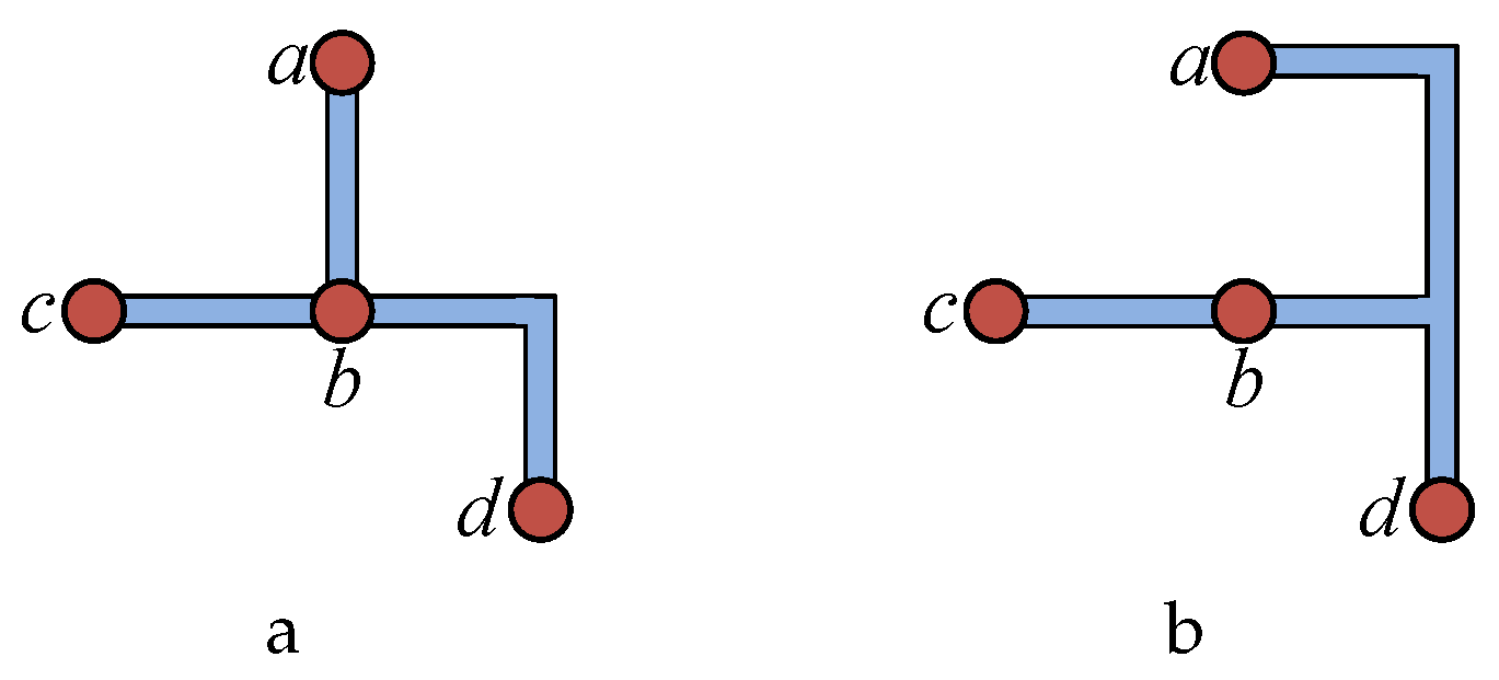
During the initialization phase, the system must complete two key tasks: (1) reducing loops formed by connection pairs to enhance channel reuse (2) and initializing the particle swarm. Connection pairs may form loop structures; for example, three connection pairs, , , and , create a cycle. If the execution time intervals of the corresponding fluid transportation tasks do not significantly overlap, one of the connection pairs can be removed, allowing its task to be executed through the channels formed by the remaining two connection pairs. For instance, removing the connection pair enables the reuse of the flow path formed by and to transport fluid between nodes c and a. For loops formed by multiple connection pairs, we identify the connection pair with the minimum total conflict time with other pairs. If the total conflict time between and all other connection pairs in the loop is less than a threshold T, then is removed, and its fluid transportation task is reassigned to other connection pairs. Otherwise, all connection pairs are retained. The choice of threshold T is critical: a value that is too large increases the conflict time of fluid transportation tasks, while a value that is too small prevents channel reuse, increasing the cost of CFMBs. Since precise transportation time depends on the routing result and flow rate, we assume that each fluid transportation task lasts 3 s during the preprocessing stage for conflict estimation. This estimation is based on a default flow rate of 10 mm/s, which is consistent with the flow rate used in the application mapping phase.
To optimize the system, all nodes and components are assigned unique identifiers. Suppose the total number of connection pairs is
n; then the particle dimension is also
n. The encoding format of a particle is
, where
represents the connection mode of the
i-th connection pair,
is the source node,
is the destination node, and
represents the selected connection type between these nodes. During initialization,
and
are set as the source and destination nodes of the
i-th connection pair, while
is randomly chosen from four possible connection options [
32]. After testing, the particle swarm size is set to 100. Once the particle swarm is initialized, each particle updates its velocity and position iteratively. This process requires frequent computations of three types of information: (1) the obstacle-crossing condition of each routing edge; (2) crossovers between different connection pairs under different selection modes; and (3) the estimated total conflict time when connection pairs intersect. To improve algorithm efficiency, we compute and store these data using hash tables during preprocessing:
Obstacle traversal table: Let be the set of nodes and be the set of components. For the k-th connection pair , the number of components it traverses under different connection modes is computed, and all traversed components are recorded as the set .
Crossover calculation: The intersections of all connection pairs under different selection modes are computed.
Conflict time calculation: The conflict duration between fluid transportation tasks of different connection pairs is recorded. For instance, if connection pair operates during time intervals and , and operates during and , the conflict duration between them is 2 s.
These preprocessing and optimization measures enable the system to perform subsequent particle swarm optimization calculations more efficiently, significantly reducing the algorithm’s runtime.
4.1.2. Hybrid Particle Swarm Optimization
In this step, the algorithm integrates the OED method into the genetic algorithm’s crossover operator and incorporates crossover and mutation operators into the particle swarm algorithm, achieving efficient particle updates. Although we adopt a swarm-based routing strategy inspired by particle behaviors, our model does not treat fluid as discrete particles in a physical sense. Instead, all fluid transport is modeled under the continuum assumption, which is widely applicable at the micrometer scale in continuous-flow microfluidic systems, as discussed in [
33]. The “particle swarm” term refers solely to the scheduling heuristic, not to a discretized fluid model.
We choose the HPSO algorithm as the core method for solving the conflict-aware routing problem in microfluidic chips, mainly because of its excellent multi-objective optimization capability, which enables effective trade-offs among channel length, the number of intersections, and conflict time. At the same time, HPSO is suitable for handling the large-scale discrete combinatorial space involved in routing and features parallel search capabilities, which can improve solving efficiency and is particularly suitable for the initial routing of complex connection pairs. Compared with traditional algorithms, HPSO also supports the flexible adjustment of weight parameters to accommodate different optimization priorities in microfluidic applications. Additionally, by introducing a penalty function mechanism, it effectively balances optimization objectives and design constraints, ensuring the feasibility and quality of the solution.
This study innovatively integrates OED and genetic operators into the HPSO algorithm framework, significantly enhancing the performance of microfluidic chip routing optimization from multiple dimensions. On one hand, OED guides particles to perform orthogonal learning from multiple high-quality solutions, improving optimization efficiency and reducing routing conflicts caused by inter-dimensional dependencies. On the other hand, genetic operators enhance the exploration ability of the solution space, effectively maintaining solution diversity and preventing premature convergence. In addition, the algorithm achieves a dynamic balance between “exploration and exploitation” through adaptive adjustment of inertia weight and crossover probability. Overall, the HPSO-OED-GA hybrid framework not only improves solution quality and efficiency but also enhances the adaptability to complex trade-offs between routing constraints and multiple objectives, providing strong support for generating high-quality, low-conflict microfluidic channel layouts. To facilitate the understanding of the mathematical expressions and symbols used in this section, we provide a list of notations in Nomenclature.
The mutation operation is as follows: assuming the particle encoding is , we first randomly generate a random number i in the interval , then execute the operation a with probability , and with probability execute operation b:
(a) Randomly change the value in the particle encoding, updating the connection selection method of the i-th connection pair.
(b) Select the i-th connection pair, where the source node is and the destination node is . If there exists a node x that is connected to node , then set in of the particle encoding to x, changing the path of the i-th connection pair to -x-, maintaining connectivity between and .
The literature [
34] integrates the OED method into the PSO algorithm, forming an orthogonal learning (OL) strategy. This strategy constructs guide particles
based on the particle’s historical best position
and the neighborhood’s historical best position
to guide particle updates. The particle update method is shown as follows:
where
is the inertia weight,
c is the acceleration factor, and
r is a random number in the range
.
Since the routing problem in this section belongs to discrete PSO problems, the above particle update method cannot be used directly. This section integrates the OED method into the particle’s crossover process. Let the current particle be , with each dimension of the particle corresponding one-to-one with connection pairs, where the i-th dimension corresponds to the connection method of the i-th connection pair.
For the i-th dimension of , if it is consistent with , then the i-th dimension remains unchanged; otherwise, under the premise of not affecting the connectivity between the source node and target node of the i-th connection pair, the i-th dimension of is set to the i-th dimension of with a certain probability. For example, if particle is and particle is , both have four dimensions. Among them, the first, third, and fourth dimensions of and are different. If the third dimension remains unchanged, the updated particle would be .
Each particle corresponds to a routing solution, and its fitness value is related to the total channel length, number of intersections, and total conflict time
of the routing. The calculation of
is shown as follows:
where
is the overlap time between the transportation tasks of connection pair
and connection pair
.
is a 0–1 variable; if the channels formed by connection pair
and connection pair
have an overlap or intersection, its value is 1; otherwise, it is 0.
The fitness function is shown as follows:
where
is the number of intersections,
L is the total channel length, and
is the total conflict duration between different connection pairs. The coefficients
are determined through experiments as
,
,
.
The OED method uses pre-built orthogonal arrays (OA) to design experimental combinations to discover optimal combinations. Let the global best particle be and the historical best particle be . The guide particle for particle is constructed using the OED method from and . All particles have the same dimension, which is the number of connection pairs D. For a two-level D-dimensional orthogonal experimental design, OA satisfies the following properties: (a) OA is a binary matrix, with element values of 0 or 1, and (b) the number of occurrences of 0 and 1 in each column is equal.
The OA construction method is as follows: The number of rows
, and the number of columns is
D. Let
. First, construct the elements with column numbers that are powers of 2, as shown in Equation (
10):
where
,
,
. Other elements are constructed as shown in Equation (
11):
where
,
,
,
.
The construction method for guide particle is as follows:
- 1.
Construct orthogonal matrix OA.
- 2.
Construct experimental particles . For the j-th dimension of , if the value of the i-th row and j-th column of OA is 1, then select the j-th dimension of as the value; otherwise, select the j-th dimension of as the value. .
- 3.
Based on
M experimental particles, conduct orthogonal experiments to construct particle
. Calculate the fitness value of each
, and compute the
value (the score of the
q-th level of the
j-th dimension):
where
is the fitness value of
, and
is a 0–1 variable, which is 1 when the value of the
i-th row and
j-th column of OA is
q; otherwise, it is 0.
- 4.
If , select the j-th dimension of as the value of the j-th dimension of ; otherwise, select the j-th dimension of as the value.
- 5.
Compare the fitness of the particle with the best fitness in the set and the fitness of , and select the better one as the guide particle .
Other works often have particles learn first from the individual cognitive component and then from the social cognitive component after mutation. However, this may lead to oscillation phenomena, reducing the algorithm’s search capability [
34]. This section applies the OED method to discrete PSO problems, constructing guide particles based on the individual historical best and the global historical best, and performs crossover between mutated particles and guide particles. The particle update method is shown as follows:
where
represents the inertia weight,
represents the mutation operation (also representing the particle’s velocity),
represents the OED operation, and
represents the crossover operation (also representing the particle’s cognitive component).
is the individual historical best, and
is the global historical best.
is a probability value. The parameters
and
change linearly during the iteration process, calculated as shown in Equations (
14) and (
15), respectively:
where
is the initial value of
,
is the final value, iterators is the total number of iterations, and
is the current iteration round.
where
is the initial value of
, and
is the final value.
The particle’s velocity update is shown in Equation (
16):
The guide particle
constructed by the OED operation is represented as
where
and
are two different particles, and the calculations of
and
are shown in Equation (
12).
Particles learn from the particle
constructed by the individual best and the global best, and its cognitive component is represented as
where
represents the crossover probability between the current particle and the guide particle.
4.1.3. Particle Adjustment in HPSO-CAR
After particles complete their flight, the routing solution corresponding to the global best particle obtained by HPSO-CAR may pass through components that do not meet the constraint conditions. Therefore, this step needs to use obstacle avoidance strategies to adjust channels that pass through components, making them bypass all components. Additionally, it is necessary to prevent channels corresponding to mutually exclusive connection pairs from sharing or crossing each other. Thus, after obstacle avoidance, path planning strategies are needed to avoid this situation.
First, channels that traverse components (i.e., obstacles) need to be adjusted to bypass components. If changing the selection can bypass components, then change the selection; if changing the selection alone cannot bypass components, then select one or multiple corner points of components as transit points to bypass components. The specific process of the obstacle avoidance strategy is as follows [
32]:
- 1.
For the edge corresponding to the i-th dimension of the particle, determine whether it intersects with any obstacle components by consulting the obstacle traversal table. If the edge avoids all obstacles, proceed to examine the next edge; otherwise, execute step (2).
- 2.
If all components can be avoided through selection 0 or selection 1, use the corresponding selection to replace the original selection ; otherwise, execute step (3).
- 3.
Determine all components that passes through via the obstacle traversal table, and sort them in non-descending order according to the distance from to the center points of these components. Let the arrangement table of traversed components be . Let the starting point and the component that currently needs to be avoided be , ; then, execute step (4).
- 4.
Select the corner point from component C that is closest to the perpendicular distance from the straight line , and calculate the connection method between point s and corner point . Priority is given to selection 0 or selection 1; if both these selections pass through components, use selection 2 or selection 3, and add its component traversal information to the obstacle traversal table. Let , . If , execute step (5); otherwise, continue to execute step (4).
- 5.
Calculate the connection information between s and , and add its component traversal information to the obstacle traversal table.
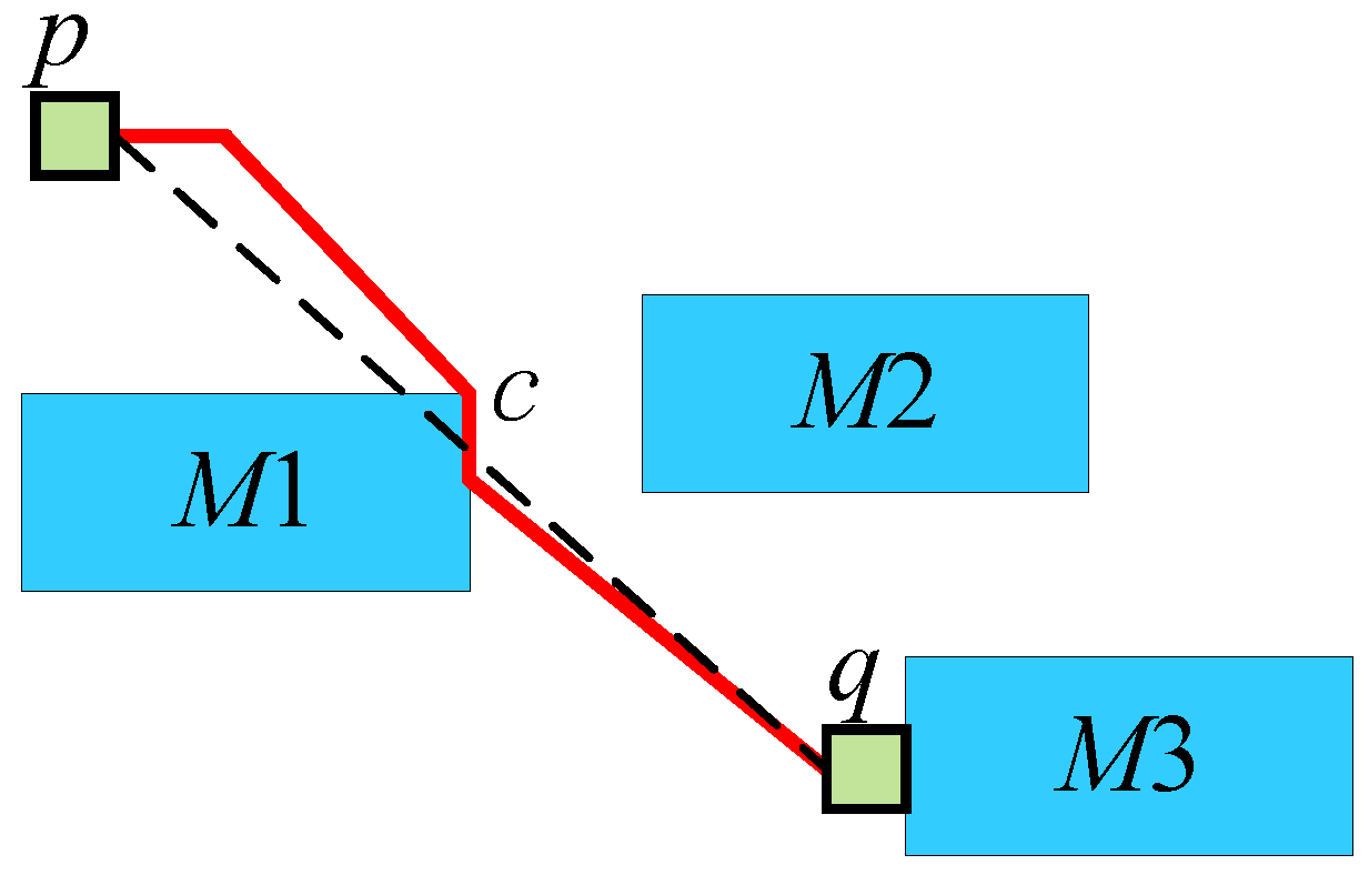
Figure 6 shows an example of the fourth step above. Points
p and
q cannot avoid passing through components using all four connection methods. At this point, set
p as
s, and the point closest to the straight line
(shown as a dotted line in the figure) is the corner point
c at the upper right of component
. At this time, use selection 0 to connect
(shown by the red line in the figure). Subsequently, set
c as
s, use selection 0 to connect
, and complete the obstacle avoidance.
Additionally, mutually exclusive connection pairs cannot have crossings or channel sharing. To solve this problem, a path planning strategy is proposed with the following specific steps:
- 1.
Construct a graph , where represents the intersections and nodes that exist in the CFMBs after executing the obstacle avoidance step and represents the connection relationship between nodes in the graph, and record the set of edges used by each connection pair.
- 2.
Calculate the crossing situations between all mutually exclusive connection pairs, and record the connection pairs that produce mutual exclusion in the mutual exclusion table.
- 3.
For mutually exclusive connection pairs that produce crossings or channel sharing, use the DFS algorithm to calculate their minimum-conflict paths and from the source node to the destination node, respectively. The minimum-conflict path is the path with the minimum conflict time among the set of paths from the source node to the destination node. If the conflict time of with other connection pairs is less than or equal to the conflict time of with other connection pairs, modify the flow path of to ; otherwise, modify the flow path of to .
When a connection pair uses a flow path, it will produce sharing or crossing with the paths used by other connection pairs. The total conflict time of is the sum of the conflict times between and these connection pairs. When searching for the flow path of using the DFS algorithm, the flow path that minimizes the total conflict time of in the solution space is the minimum-conflict path.

