Abstract
In this paper, a miniaturized broadband bandstop filter with a simple structure is proposed, synthesized, and developed. The proposed broadband bandstop filter is designed using asymmetrically loaded parallel-coupled microstrip lines, resulting in five transmission zeros within the stopband. Closed-form formulas of the entire set of generated transmission zeros are derived to guide a practical design procedure. To demonstrate the effectiveness of the proposed concept and synthesis method, a miniaturized broadband bandstop filter centered at 3 GHz with a 20 dB rejection bandwidth of about 100% is designed, fabricated, and measured. The core circuit size of the developed broadband bandstop filter is only 0.5 λg × 0.1 λg (31.2 mm × 6.5 mm).
1. Introduction
In modern microwave communication systems, the role of broadband bandstop filters has become increasingly significant. As communication systems grow more complex, interference from unwanted frequfugureency bands poses a critical challenge to signal integrity and system performance. Unlike bandpass filters [1], which allow a specific frequency range to pass through, bandstop filters are widely employed to suppress particular frequency ranges while permitting other signals to pass unimpeded. Currently, several common design methods for bandstop filters are widely used in the field of microwave communication. The most common method employed for designing microstrip bandstop filters is based on the open-circuit stub-loaded transmission line structure [2,3,4,5]. This design is straightforward and offers design flexibility. Moreover, its variants are widely utilized in harmonic suppression for bandpass filters and in RF chokes among active circuits [6,7]. However, broadband bandstop filters designed using this method often suffer from a large size, which consequently limits their application in miniaturized systems. Another frequently used method for designing bandstop filters involves the use of transmission lines with shunt-loaded resonators, which is also noted for its design simplicity [8,9,10]. This technique is also suitable for dual-band, multi-band bandstop filters and ultra-wideband bandpass filters with notched bands [11,12,13]. Nevertheless, similar to the previously mentioned approach, broadband bandstop filters designed in this way are typically bulky. In order to minimize circuit dimensions, researchers have designed a series of broadband bandstop filters based on signal interference techniques [14,15,16]. Similarly, to minimize circuit dimensions, parallel-coupled microstrip lines are commonly employed as the basis for designing broadband bandstop filters [17,18,19,20]. Furthermore, in order to continuously enhance the performance of bandstop filters, these two aforementioned methods have been innovatively integrated [21,22]. In this scenario, however, the sizes of these bandstop filters remain relatively large.
In this paper, a comprehensive design method for a compact broadband bandstop filter is proposed. The developed bandstop filter is constructed using asymmetrically loaded parallel-coupled microstrip lines, and five transmission zeros within the stopband are achieved accordingly. In order to guide a practical design, the equivalent circuit model is developed, and the closed-form equations for these transmission zeros are derived. The simulation and experimental results are in good agreement, which validates the correctness of the design theory.
2. Broadband Bandstop Filters
Schematics of the presented broadband bandstop filters are given in Figure 1. According to this figure, bandstop filter I consists of two sets of parallel-coupled microstrip lines, whereas the open-circuited sections of one set are interconnected. Bandstop filter II is derived from bandstop filter I by asymmetrically loading an open-circuited stub with quarter-wavelength length at the operating frequency. The specific parameters of these parallel-coupled microstrip lines are provided in Figure 1b. Owing to the quasi-TEM propagation mode of microstrip lines, the phase velocities of the even and odd modes in coupled microstrip lines are slightly different. This discrepancy results in slight differences between the values of θe and θo. According to Reference [23], when using a Rogers 4003C substrate (a loss tangent of 0.0027, a dielectric constant of 3.38, and a thickness of 0.813 mm), the specific values of θe and θo for the quarter-wavelength coupled microstrip line are about 90.6° and 89.4°, respectively, at the center frequency. Given that the values of θe and θo are extremely close, the subsequent analysis is simplified by assuming θe = θo = θ.
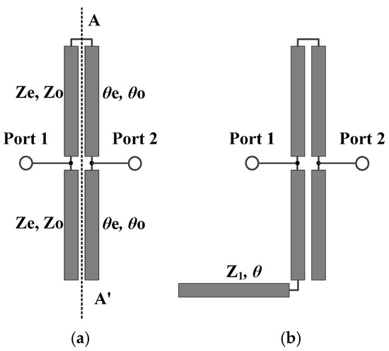
Figure 1.
Schematics of broadband bandstop filters, (a) bandstop filter I, (b) bandstop filter II.
By conducting an odd–even mode analysis on bandstop filter I, the corresponding odd–even mode input admittances can be obtained as follows:
Given the relationship between S21 and the odd-mode and even-mode input admittances (Yine and Yino), we obtain the following:
setting S21 = 0 allows the identification of two transmission zeros (θz1, θz2) for bandstop filter I, which can be derived as follows:
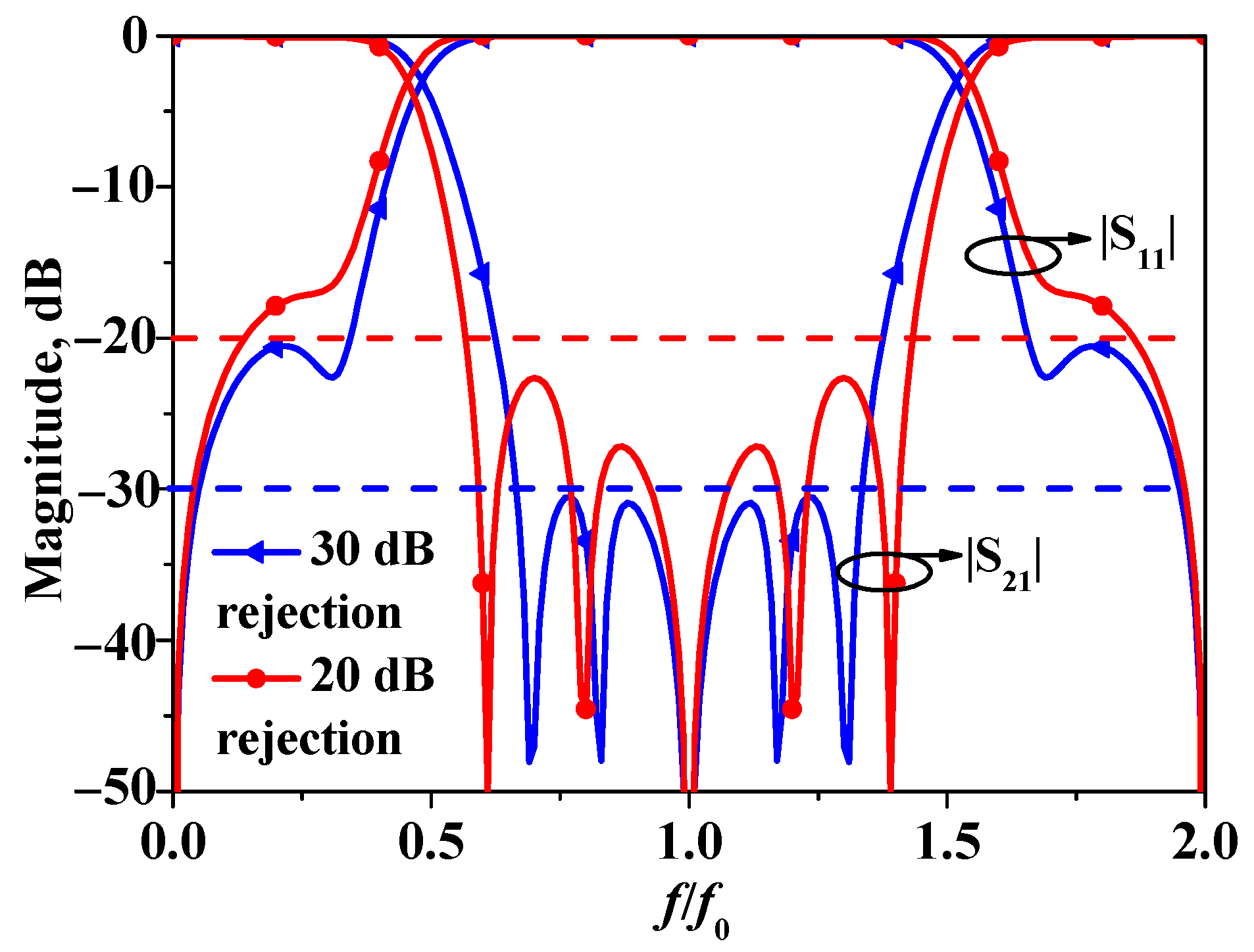
In the context of general bandstop filters, a higher in-band rejection level is typically deemed more desirable. However, it is generally challenging to achieve a high in-band rejection level while simultaneously obtaining a wide stop-band width. Figure 2 presents two design schemes. As illustrated, when the in-band rejection level is set at 30 dB, the operational bandwidth of the bandstop filter is limited to only 78%. Conversely, when the in-band rejection level is reduced to 20 dB, the operational bandwidth of the bandstop filter can reach 100%. Given that the objective of this design is to develop a wideband bandstop filter, a comprehensive evaluation of various factors has been conducted. Consequently, the one with in-band rejection over 20 dB has been selected as the optimal choice.
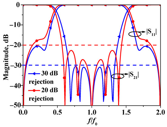
Figure 2.
Simulated results of a bandstop filter with in-band rejection over 20 dB (Ze = 90 Ω, Ze = 40 Ω, Z1 = 120 Ω) and over 30 dB (Ze = 89 Ω, Ze = 41 Ω, Z1 = 240 Ω).
Moreover, two stubs in bandstop filter I are equivalent to quarter-wavelength open-circuited stubs for the input and output ports, thereby generating an additional transmission zero at the center frequency, leading to three transmission zeros across the stopband. According to Equations (4) and (5), it can be observed that, for bandstop filter I, the positions of transmission zeros θz1 and θz2 are primarily determined by the odd–even mode impedance ratio. To illustrate the impact of the odd/even-mode impedances on bandstop filter I more clearly, Figure 3 presents the S-parameters of bandstop filter I under different combinations of odd–even mode impedances. As shown in Figure 3, the stopband attenuation level of bandstop filter I is truly determined by the ratio of the odd/even-mode impedances. Furthermore, based on the results in Figure 3 and taking into account the stopband rejection of the filter and practical fabrication tolerances, Ze = 90 Ω and Zo = 40 Ω are selected for the subsequent filter design.
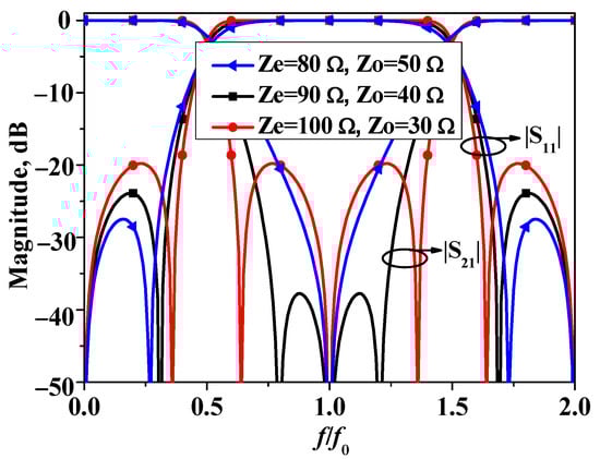
Figure 3.
Simulated S11 and S21 of bandstop filter I versus different combination of Ze and Zo.
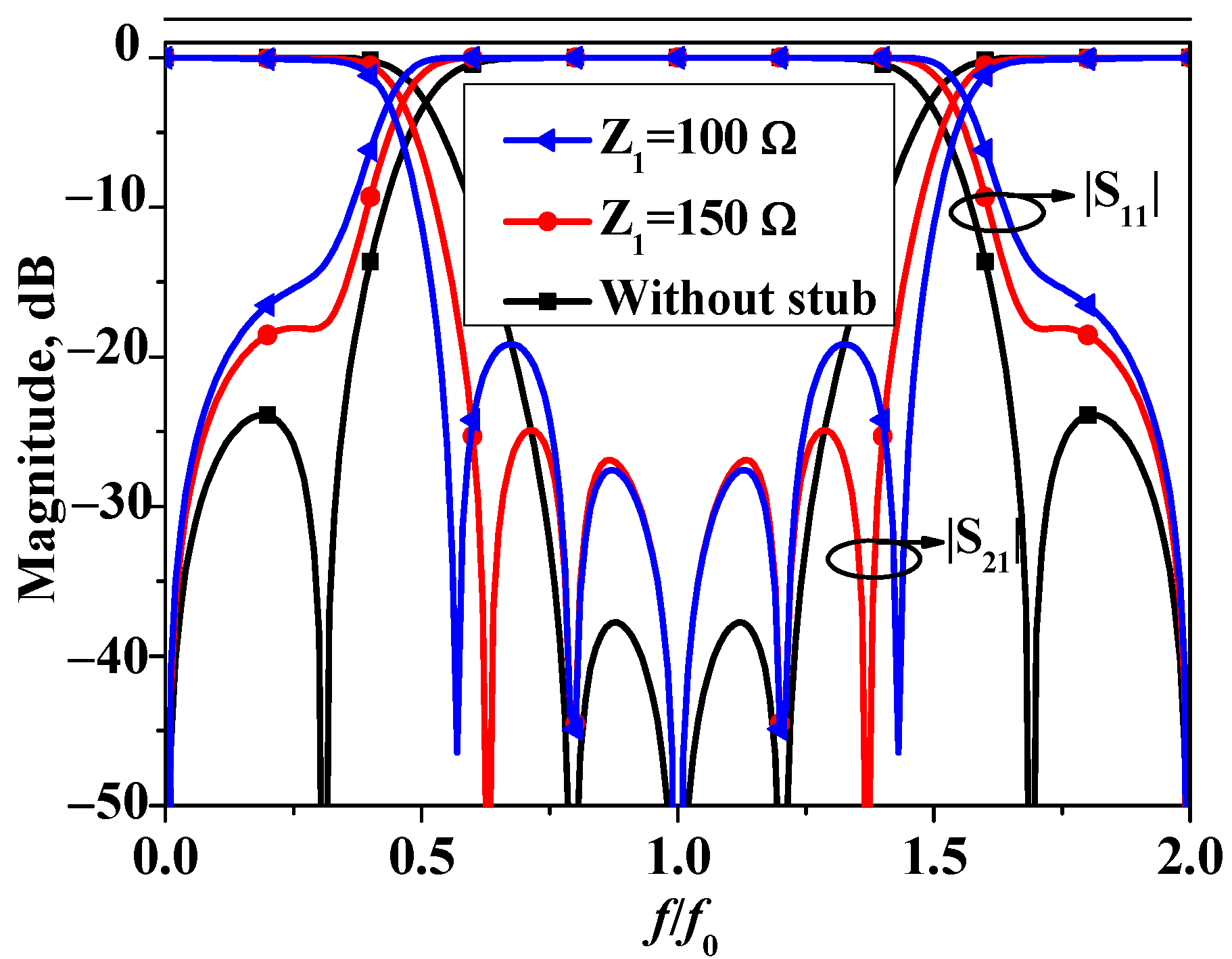
To further enhance the performance of bandstop filter I, a quarter-wavelength-length open-circuited stub with an impedance of Z1 is asymmetrically loaded to one of the open ends of bandstop filter I, which is shown in Figure 1b. Figure 4 exhibits S-parameters of the two bandstop filters under different Z1 values. It can be observed from Figure 4 that the introduction of the open-circuited stub results in two additional transmission zeros. This enhancement increases the stopband bandwidth of the bandstop filter without affecting the previous three transmission zeros.
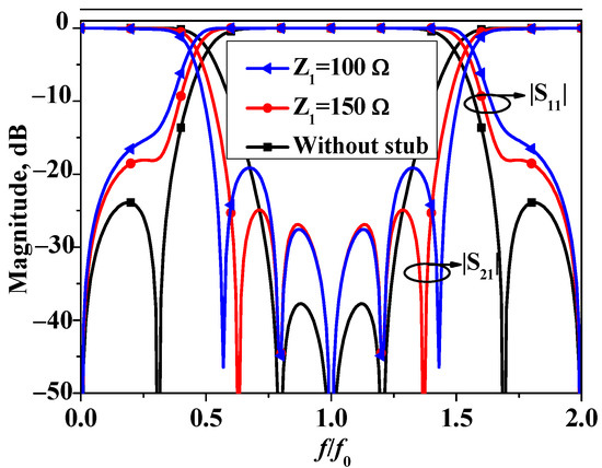
Figure 4.
Simulated S11 and S21 of bandstop filter I and II. (Ze = 90 Ω, Zo = 40 Ω).
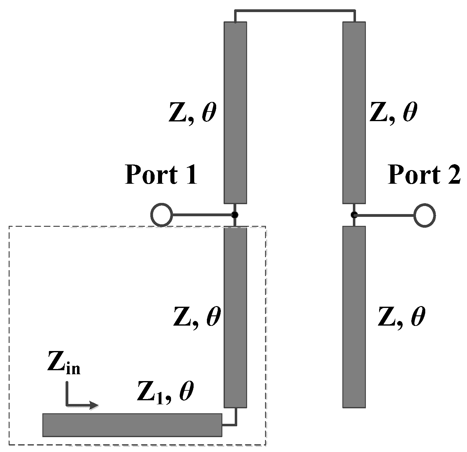
In order to determine the closed-form formulas for the additional transmission zeros, the transmission line equivalent circuit for bandstop filter II, based on conventional coupled microstrip line theory [24], is provided in Figure 5. According to Figure 5, the input impedance of the structure in the dashed-line box can be derived as follows:
where
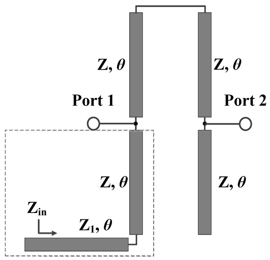
Figure 5.
Transmission line equivalent circuit of bandstop filter II.
By setting Yin = 1/Zin = 0, the following relationship can be derived:
Therefore, the two newly generated transmission zeros are as follows:
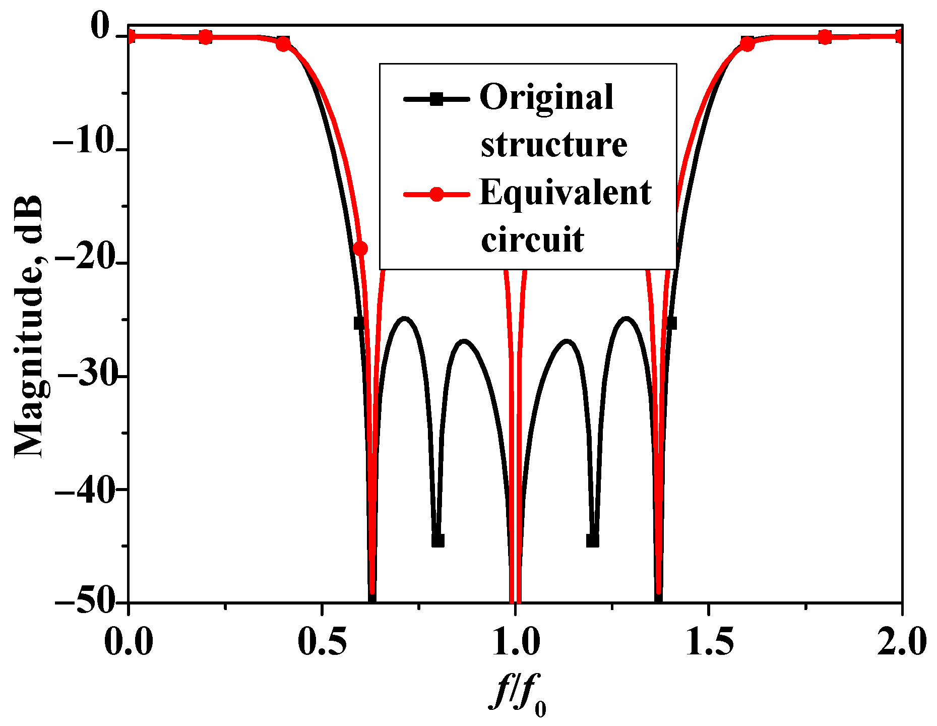
To verify the theoretical analysis and the derived formulas, Figure 6 presents the transmission coefficients of the original structure and the transmission line equivalent circuit of bandstop filter II. As shown in Figure 6, for the equivalent circuit, when the coupling between the two sets of microstrip lines is neglected, transmission zeros θz1 and θz2 will disappear. The positions of the three zeros in the equivalent circuit are basically consistent with those of the transmission zeros generated by the open-circuited stubs in the original structure. This validates the theoretical analysis and the derived closed-form formulas, providing a solid foundation for the subsequent fabrication and testing of the bandstop filter.
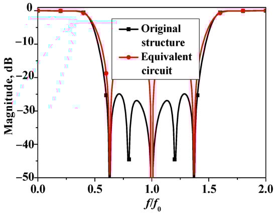
Figure 6.
Transmission coefficients of original structure and transmission line equivalent circuit of bandstop filter II (Ze = 90 Ω, Zo = 40 Ω, Z1 = 150 Ω).
3. Results and Discussion
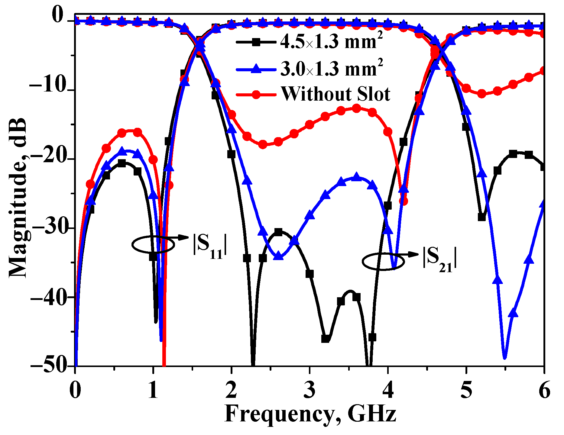
The layout of the proposed broadband bandstop filter II is exhibited in Figure 7. In the preceding analysis, for the sake of simplicity, θe and θo were assumed to be equal, denoted as θ. However, in practice, to ensure the performance of the filter, certain measures still need to be taken to equalize the two values. In order to equalize θe and θo, the primary method involves slotting the inner side of the coupling line. The size of the etched slot for equalization between the two can be obtained via a full-wave simulator. Simulated results of bandstop filter I with different sizes for the etched slot have been plotted in Figure 8. As shown in Figure 8, the size of the etched slot is selected as 4.5 × 1.3 mm2 to realize equalization.
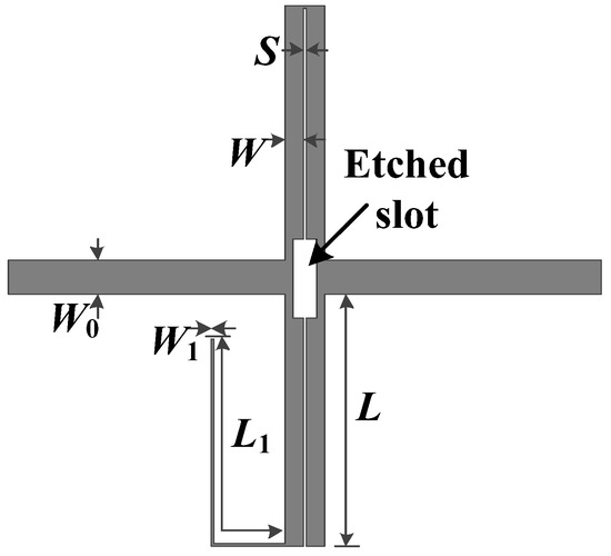
Figure 7.
Layout of proposed broadband bandstop filter II. (W0 = 1.95 mm, L = 16.5 mm, W = 1.05 mm, S = 0.1 mm, L1 = 15.9 mm, and W1 = 0.2 mm).
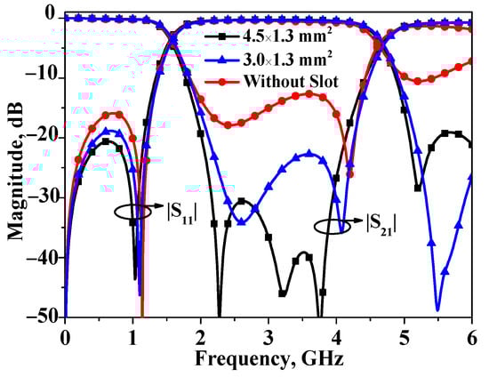
Figure 8.
Simulated results of bandstop filter I with different sizes for the etched slot.
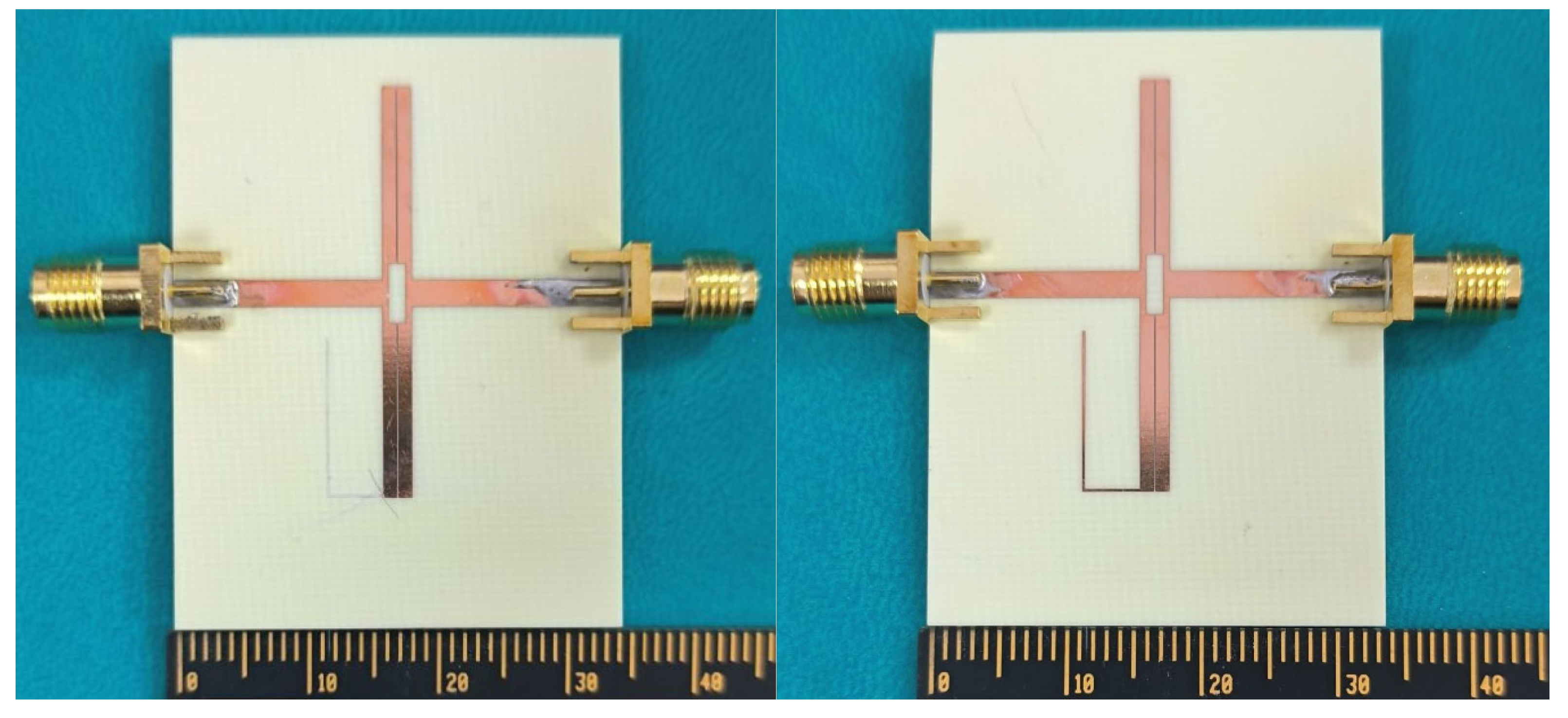
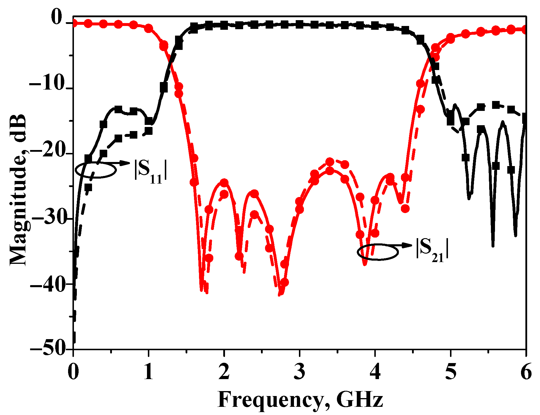
Photographs of the proposed broadband bandstop filters I and II are shown in Figure 9. Based on the aforementioned analysis, the proposed broadband bandstop filter is simulated and designed on an RO4003c substrate with a relative dielectric constant of 3.55 and a thickness of 0.813 mm. The simulated and measured S-parameters of bandstop filters I are depicted in Figure 10. The simulation results are obtained by the full-wave simulation software Ansys HFSS 2020 R2, and the testing results are obtained by the Keysight 5071C. As can be seen from the figure, the results match with each other very well. The measured stopband 20 dB insertion loss bandwidth is about 72% (2.02 GHz ~ 4.17 GHz), and the center frequency is 3 GHz. The core circuit size is 0.5 λg × 0.03 λg (31.2 mm × 2.2 mm) (λg: the guided wavelength at the center frequency).
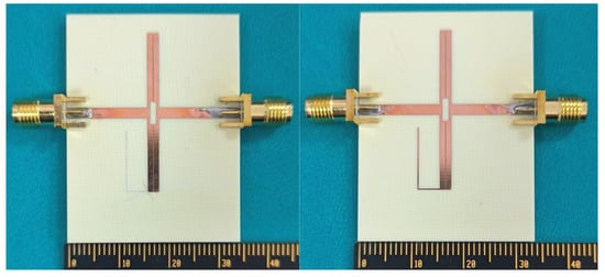
Figure 9.
Photographs of broadband bandstop filters I and II.

Figure 10.
Simulated and measured results of broadband bandstop filter I.
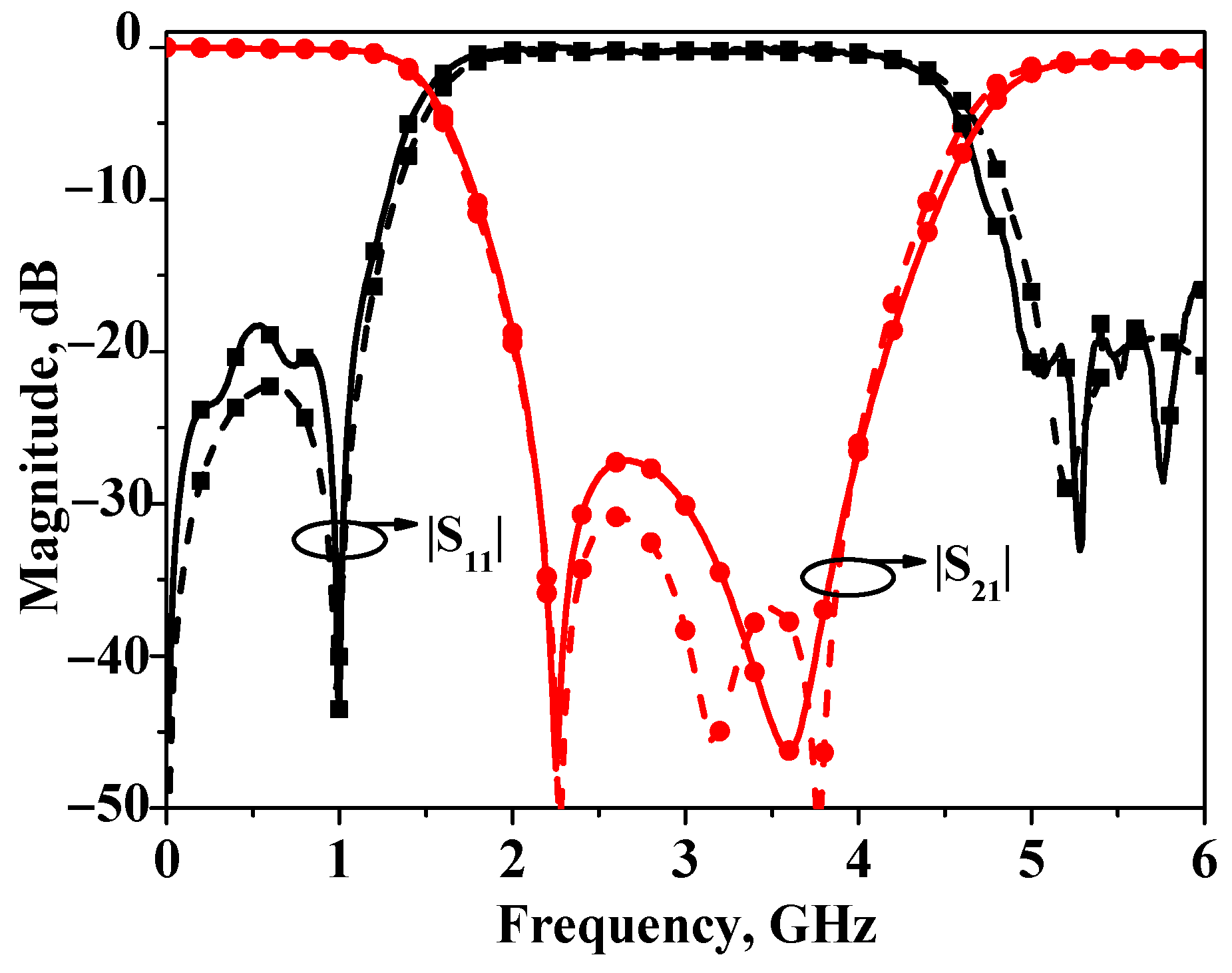
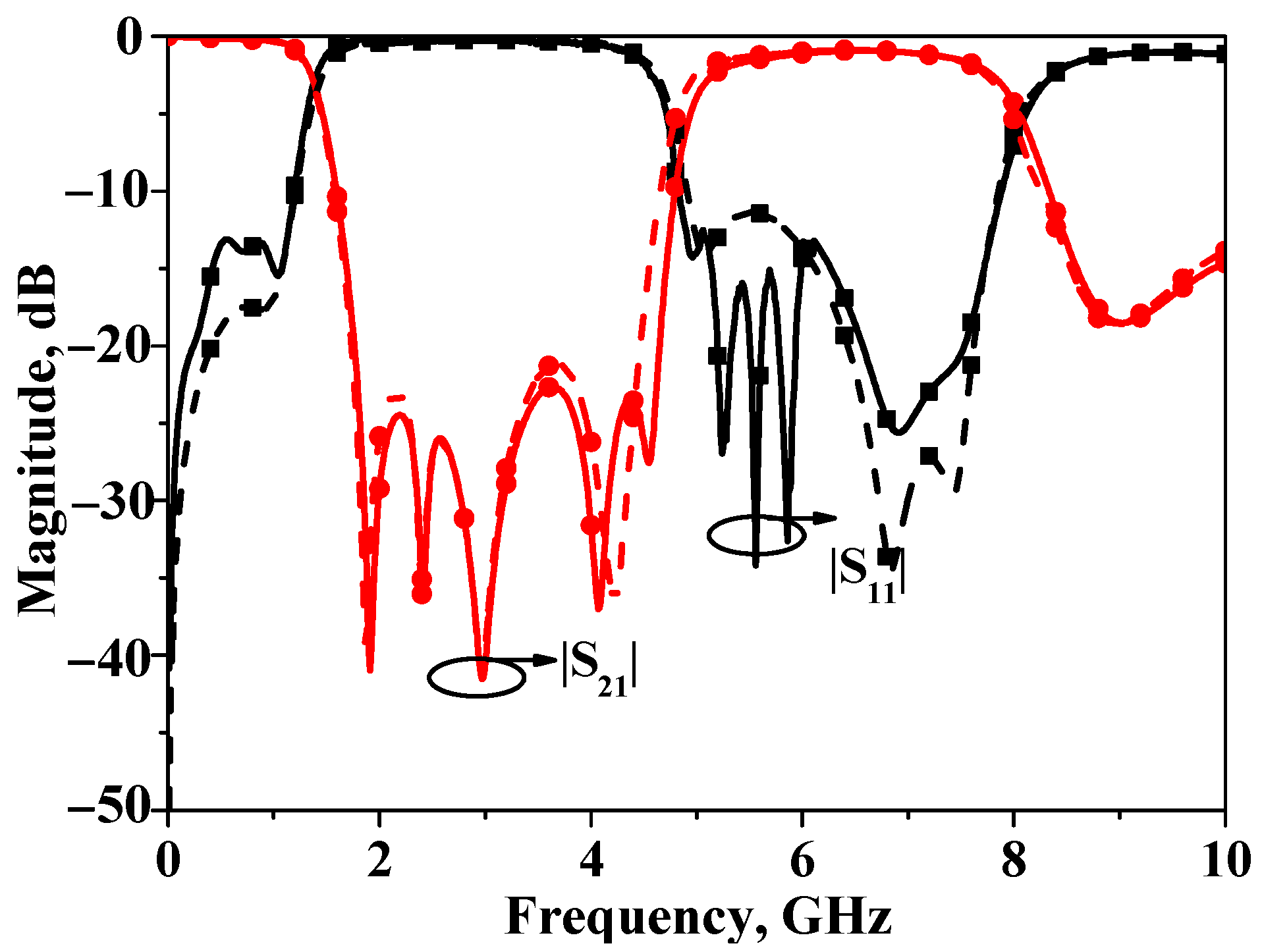
The simulated and measured S-parameters of bandstop filters II are plotted in Figure 11. As is illustrated by this figure, the measured stopband 20 dB insertion loss bandwidth is about 100% (1.51~4.52 GHz), and the center frequency is also 3 GHz. The core circuit size is 0.5 λg × 0.1 λg (31.2 mm × 6.5 mm). In order to demonstrate the wideband performance of bandstop filter II, the corresponding response is illustrated in Figure 12.

Figure 11.
Simulated and measured results of broadband bandstop filter II.
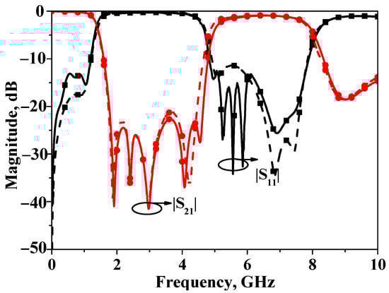
Figure 12.
Simulated and measured wideband results of broadband bandstop filter II.
To further demonstrate the performance of the proposed broadband bandstop filter, comparisons with the previously reported bandstop filters are tabulated and listed in Table 1. As shown in Table 1, among broadband bandstop filters with a stopband bandwidth exceeding 100% and an attenuation level greater than 20 dB, the proposed filter in this paper achieves the smallest size and a relatively simpler circuit structure. This demonstrates the significant advantages of the proposed design in terms of miniaturization and simplicity.

Table 1.
Performance summary of the proposed broadband bandstop filter and state-of-the-art designs.
4. Conclusions
In this paper, a novel miniaturized broadband bandstop filter with a simple structure is presented. The filter is designed using asymmetrically loaded parallel-coupled microstrip lines, achieving five transmission zeros within the stopband. Closed-form formulas for these transmission zeros are all derived to facilitate practical design. A prototype centered at 3 GHz with a 20 dB rejection bandwidth of approximately 100% is designed, fabricated, and measured, demonstrating the effectiveness of the proposed method. This work provides a comprehensive design approach for compact broadband bandstop filters, highlighting the importance of transmission zeros in enhancing filter performance.
Author Contributions
Conceptualization, C.S.; methodology, C.S. and K.X.; software, R.C. and X.Z.; validation, C.S. and K.X.; formal analysis, C.S.; investigation, R.C.; resources, C.S., K.X. and R.C.; data curation, X.Z. and R.C.; writing—original draft preparation, C.S. and K.X.; writing—review and editing, C.S. and X.Z.; visualization, R.C.; supervision, C.S.; project administration, C.S. and K.X.; funding acquisition, C.S., K.X. and R.C. All authors have read and agreed to the published version of the manuscript.
Funding
This work was supported by the National Natural Science Foundation of China under grant 62201291, the Natural Science Research Project of Jiangsu Higher Education Institutions (grants 23KJD510002 and 24KJA540001), and the Natural Science and Technology Project of Jiangsu College of Engineering and Technology (grants GYKY/2024/5 and GYKY/2025/2).
Data Availability Statement
The data presented in this study are available from the corresponding author upon request.
Conflicts of Interest
The authors declare no conflicts of interest.
References
- Liu, J.; Wu, K.-L. Transitioning from Analytical to Numerical Methods for Synthesizing Microwave Bandpass Filters. In Proceedings of the 2024 IEEE International Microwave Filter Workshop (IMFW), Cocoa Beach, FL, USA, 21–23 February 2024; pp. 43–46. [Google Scholar]
- Chen, F.-C.; Zhang, N.-Y.; Zhang, P.-S.; Chu, Q.-X. Design of ultra-wideband bandstop filter using defected ground structure. Electron. Lett. 2013, 49, 1010–1011. [Google Scholar] [CrossRef]
- Chen, H.; Wang, X.; Lu, G. A wideband bandstop filter with two independently controllable equal-ripple levels. Electron. Lett. 2021, 22, 4–6. [Google Scholar] [CrossRef]
- Velidi, V.K.; Guntupalli, A.B.; Sanyal, S. Sharp-rejection ultra-wide bandstop filters. IEEE Microw. Wirel. Compon. Lett. 2009, 19, 503–505. [Google Scholar] [CrossRef]
- Chen, H.; Jiang, D.; Chen, X. Wideband bandstop filter using hybrid microstrip/CPW-DGS with via-hole connection. Electron. Lett. 2016, 52, 1469–1470. [Google Scholar] [CrossRef]
- Tu, W.-H.; Chang, K. Compact microstrip bandstop filter using open stub and spurline. IEEE Microw. Wirel. Compon. Lett. 2005, 15, 268–270. [Google Scholar]
- Hong, J.S.; Lancaster, M.J. Microstrip Filters for RF/Microwave Applications; Wiley: New York, NY, USA, 2001. [Google Scholar]
- Yang, D.; Tian, H.; Dong, Y. Miniaturized reciprocal DMS-DGS unit and its application to single-/dual-band bandstop filters. IEEE Trans. Circuits Syst. II Express Briefs 2023, 70, 4299–4303. [Google Scholar] [CrossRef]
- Zhou, L.-H.; Ma, Y.-L.; Shi, J.; Chen, J.-X.; Che, W. Differential dual-band bandpass filter with tunable lower band using embedded dgs unit for common-mode suppression. IEEE Trans. Microw. Theory Tech. 2016, 64, 4183–4191. [Google Scholar] [CrossRef]
- Chen, F.-C.; Li, R.-S.; Qiu, J.-M.; Chu, Q.-X. Sharp-rejection wideband bandstop filter using stepped impedance resonators. IEEE Trans. Compon. Packag. Manuf. Technol. 2017, 7, 396–403. [Google Scholar] [CrossRef]
- Min, X.; Zhang, H. Design of dual-band bandstop filter based on dumbbell-shaped resonators and U-shaped slot. Prog. Electromagn. Res. Lett. 2017, 71, 133–140. [Google Scholar] [CrossRef]
- Luo, J.; Zhang, J.; Gao, S. Design of multi-band bandstop filters based on mixed electric and magnetic coupling resonators. Electronics 2024, 13, 1552. [Google Scholar] [CrossRef]
- Yoon, K.; Kim, K. Design of dual ultra–wideband band–pass filter using stepped impedance resonator λg/4 Short stubs and t–shaped band-stop filter. Electronics 2021, 10, 1951. [Google Scholar] [CrossRef]
- Mandal, M.K.; Sanyal, S. Compact bandstop filter using signal interference technique. Electron. Lett. 2007, 43, 110–111. [Google Scholar] [CrossRef]
- Divyabramham, K.; Mandal, M.K.; Sanyal, S. Sharp-rejection wideband bandstop filters. IEEE Microw. Wirel. Compon. Lett. 2008, 18, 662–664. [Google Scholar] [CrossRef]
- Sánchez-Soriano, M.Á.; Torregrosa-Penalva, G.; Bronchalo, E. Compact wideband bandstop filter with four transmission zeros. IEEE Microw. Wirel. Compon. Lett. 2010, 20, 313–315. [Google Scholar] [CrossRef]
- He, M.; Zuo, X.; Mei, H.; Li, Y. A planar sharp-attenuation ultra-wideband bandstop filter with a three section coupled-line stub. Prog. Electromagn. Res. C 2024, 146, 195–199. [Google Scholar]
- Liu, L.; Liang, X.; Fan, H.; Jin, R.; Bai, X.; Geng, J. Compact wideband bandstop filter with directly controlled rejection. IEEE Trans. Circuits Syst. II Express Briefs 2021, 68, 2282–2286. [Google Scholar] [CrossRef]
- Tang, C.-W.; Yang, C.-H.; Liao, J.-S. Design of planar wide-stopband bandstop filters with extra-high attenuation. IEEE Trans. Circuits Syst. II Express Briefs 2022, 69, 1039–1043. [Google Scholar] [CrossRef]
- Shaman, H.; Hong, J.-S. Wideband bandstop filter with cross-coupling. IEEE Trans. Microw. Theory Tech. 2007, 55, 1780–1785. [Google Scholar] [CrossRef]
- Mandal, M.K.; Divyabramham, K.; Velidi, V.K. Compact wideband bandstop filter with five transmission zeros. IEEE Microw. Wirel. Compon. Lett. 2012, 22, 4–6. [Google Scholar] [CrossRef]
- Kong, M.; Wu, Y.; Zhuang, Z.; Liu, Y. Wideband bandstop filter with extreme sharp skirt selectivity. IEEE Microw. Wirel. Compon. Lett. 2018, 28, 1104–1106. [Google Scholar] [CrossRef]
- Shi, J.; Nie, Y.; Han, P.; Zhang, W.; Cao, Q. Compact filtering phase shifter with simple structure. IEEE Microw. Wirel. Compon. Lett. 2021, 31, 1263–1266. [Google Scholar] [CrossRef]
- Pozar, D.M. Microwave Engineering; Wiley: Hoboken, NJ, USA, 2012. [Google Scholar]


Disclaimer/Publisher’s Note: The statements, opinions and data contained in all publications are solely those of the individual author(s) and contributor(s) and not of MDPI and/or the editor(s). MDPI and/or the editor(s) disclaim responsibility for any injury to people or property resulting from any ideas, methods, instructions or products referred to in the content. |
© 2025 by the authors. Licensee MDPI, Basel, Switzerland. This article is an open access article distributed under the terms and conditions of the Creative Commons Attribution (CC BY) license (https://creativecommons.org/licenses/by/4.0/).