
Bulk Acoustic Wave Resonance Characteristics of PMN-PT Orthorhombic Crystal Plates Excited by Lateral Electric Fields


 ,
,  and
and 
Abstract
1. Introduction
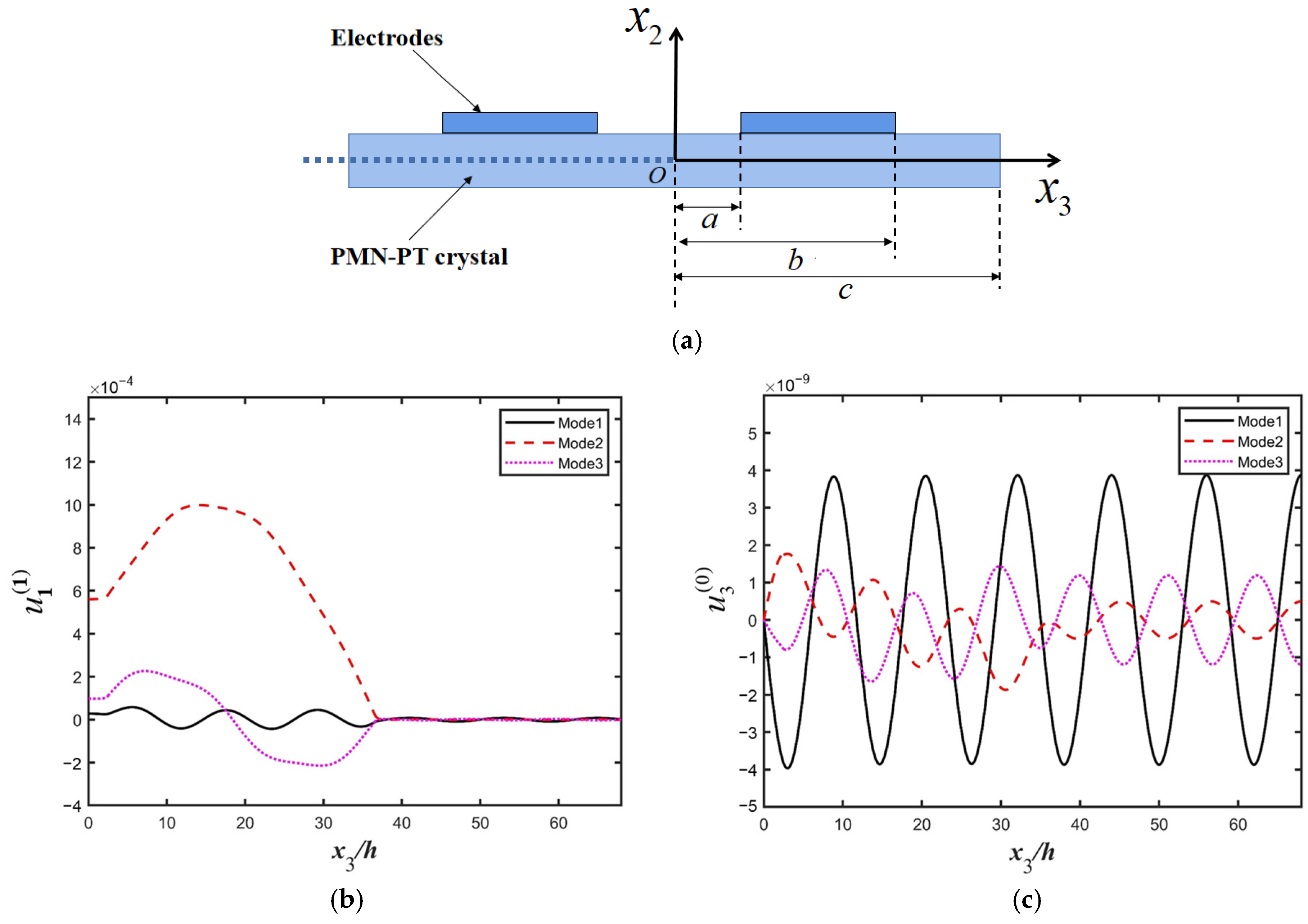
2. Model
3. Electrically Forced Vibrations of the Finite Plate
3.1. Central Non-Electrode Area
3.2. Electrode Area
3.3. External Non-Electrode Area
3.4. Boundary and Continuity Conditions
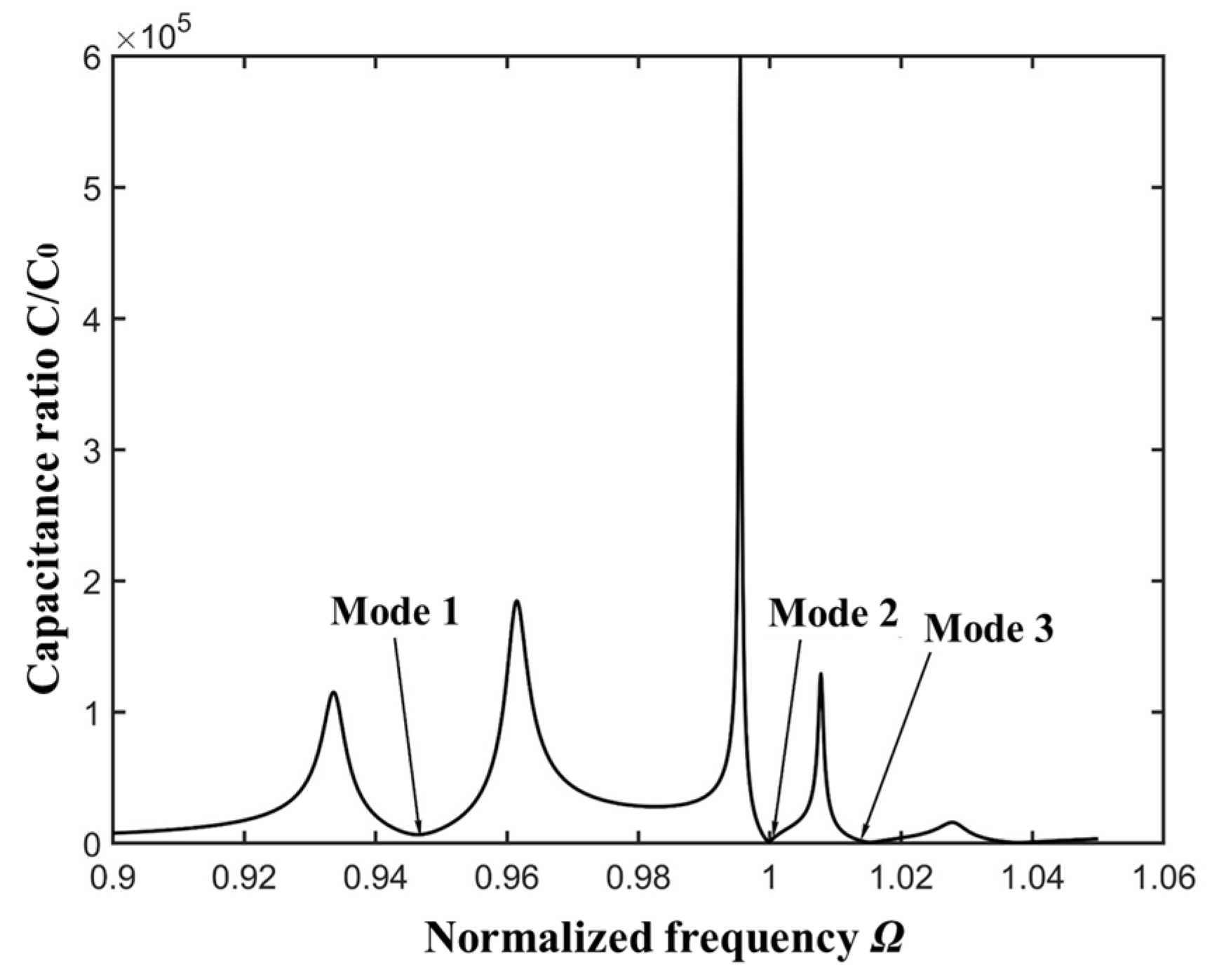
3.5. Numerical Results and Discussion
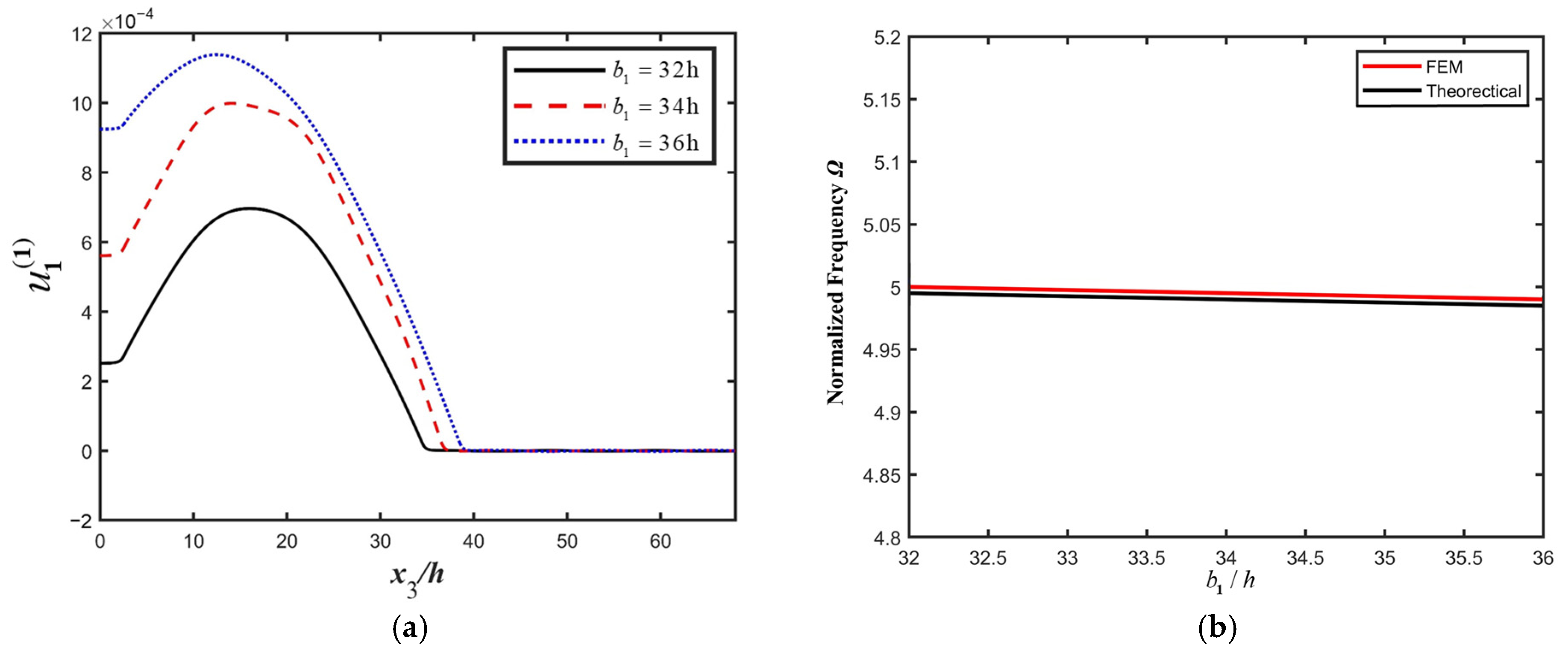
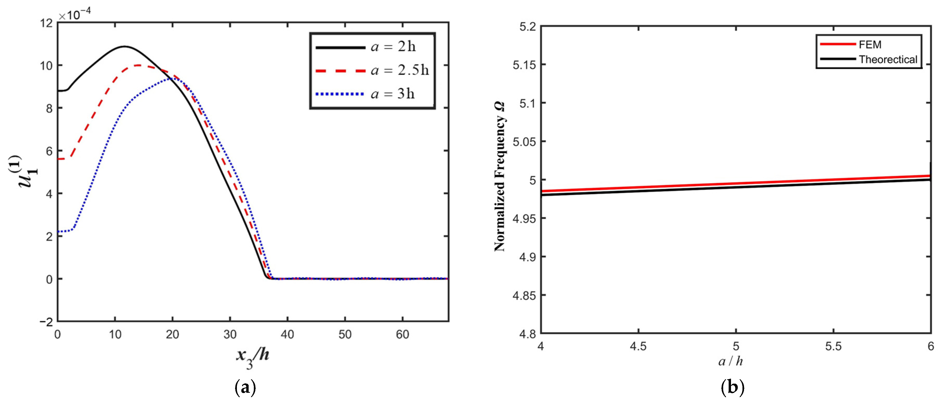
4. Influences of Structure Parameters on the Resonance Characteristics of the PMN-PT LFE Device
5. Conclusions
Author Contributions
Funding
Data Availability Statement
Conflicts of Interest
References
- Lakin, K.M.; Wang, J.S.; Kline, G.R.; Landin, A.R.; Chen, Y.Y.; Hunt, J.D. Thin Film Resonators and Filters. In Proceedings of the 1982 Ultrasonics Symposium, San Diego, CA, USA, 27–29 October 1982; pp. 466–475. [Google Scholar]
- Ruby, R.C.; Bradley, P.; Oshmyansky, Y.; Chien, A.; Larson, J.D. Thin film bulk wave acoustic resonators (FBAR) for wireless applications. In Proceedings of the 2001 IEEE Ultrasonics Symposium. Proceedings. An International Symposium (Cat. No.01CH37263), Atlanta, GA, USA, 7–10 October 2001; Volume 811, pp. 813–821. [Google Scholar]
- Ruppel, C.C.W. Acoustic Wave Filter Technology–A Review. IEEE Trans. Ultrason. Ferroelectr. Freq. Control 2017, 64, 1390–1400. [Google Scholar] [CrossRef] [PubMed]
- Bauer, T.; Eggs, C.; Wagner, K.; Hagn, P. A Bright Outlook for Acoustic Filtering: A New Generation of Very Low-Profile SAW, TC SAW, and BAW Devices for Module Integration. IEEE Microw. Mag. 2015, 16, 73–81. [Google Scholar] [CrossRef]
- Liang, C.; Peng, H.; Bao, X.; Nie, L.; Yao, S. Study of a molecular imprinting polymer coated BAW bio-mimic sensor and its application to the determination of caffeine in human serum and urine. Analyst 1999, 124, 1781–1785. [Google Scholar] [CrossRef] [PubMed]
- Reichert, P.; Deshmukh, D.; Lebovitz, L.; Dual, J. Thin film piezoelectrics for bulk acoustic wave (BAW) acoustophoresis. Lab A Chip 2018, 18, 3655–3667. [Google Scholar] [CrossRef] [PubMed]
- Yihe, H.; French, L.A.; Radecsky, K.; Cunha, M.P.d.; Millard, P.; Vetelino, J.F. A lateral field excited liquid acoustic wave sensor. IEEE Trans. Ultrason. Ferroelectr. Freq. Control 2004, 51, 1373–1380. [Google Scholar] [CrossRef] [PubMed]
- Hu, Y.; Pinkham, W.; French, L.A.; Frankel, D.; Vetelino, J.F. Pesticide detection using a lateral field excited acoustic wave sensor. Sens. Actuators B Chem. 2005, 108, 910–916. [Google Scholar] [CrossRef]
- Assylbekova, M.; Chen, G.; Pirro, M.; Michetti, G.; Rinaldi, M. Aluminum Nitride Combined Overtone Resonator for Millimeter Wave 5g Applications. In Proceedings of the 2021 IEEE 34th International Conference on Micro Electro Mechanical Systems (MEMS), Online, 25–29 January 2021; pp. 202–205. [Google Scholar]
- Hempel, U.; Lucklum, R.; Hauptmann, P. Lateral Field Excited Acoustic Wave Devices: A new Approach to Bio-Interface Sensing. In Proceedings of the 2007 IEEE International Frequency Control Symposium Joint with the 21st European Frequency and Time Forum, Geneva, Switzerland, 29 May–1 June 2007; pp. 426–430. [Google Scholar]
- Ma, T.; Zhang, C.; Feng, G. Lateral field excited Y-cut langasite bulk acoustic wave sensor. Sens. Actuators B Chem. 2011, 153, 50–53. [Google Scholar] [CrossRef]
- Wang, W.; Zhang, C.; Zhang, Z.; Liu, Y.; Feng, G. Three operation modes of lateral-field-excited piezoelectric devices. Appl. Phys. Lett. 2008, 93, 242906. [Google Scholar] [CrossRef]
- Li, Q.; Lu, L.; Tian, Y.; Yi, Z.; Liu, J.; Yang, B. High Sensitivity Surface Acoustic Wave Strain Sensor Based on PMN-PT Thick Film. In Proceedings of the 2019 20th International Conference on Solid-State Sensors, Actuators and Microsystems & Eurosensors XXXIII (TRANSDUCERS & EUROSENSORS XXXIII), Berlin, Germany, 23–27 June 2019; pp. 1866–1869. [Google Scholar]
- Peräntie, J.; Tailor, H.N.; Hagberg, J.; Jantunen, H.; Ye, Z.-G. Electrocaloric properties in relaxor ferroelectric (1−x)Pb(Mg1/3Nb2/3)O3–xPbTiO3 system. J. Appl. Phys. 2013, 114, 174105. [Google Scholar] [CrossRef]
- Wang, H.; Pan, X.; Lin, D.; Luo, H.; Yin, Z.; Elouadi, B. Dielectric and thermal evidence of phase transitions in the system of (1−x)Pb(Mg1∕3Nb2∕3)O3–xPbTiO3 crystals. Appl. Phys. Lett. 2007, 90, 252902. [Google Scholar] [CrossRef]
- Zhang, S.; Li, F. High performance ferroelectric relaxor-PbTiO3 single crystals: Status and perspective. J. Appl. Phys. 2012, 111, 031301. [Google Scholar] [CrossRef]
- Li, T.; Deng, S.; Liu, H.; Chen, J. Insights into strain engineering: From ferroelectrics to related functional materials and beyond. Chem. Rev. 2024, 124, 7045–7105. [Google Scholar] [CrossRef] [PubMed]
- Deng, C.; Zhang, Y.; Yang, D.; Zhang, H.; Zhu, M. Recent progress on barium titanate-based ferroelectrics for sensor applications. Adv. Sens. Res. 2024, 3, 2300168. [Google Scholar] [CrossRef]
- Delibas, B.; Koc, B. Single crystal piezoelectric motor operating with both inertia and ultrasonic resonance drives. Ultrasonics 2024, 136, 107140. [Google Scholar] [CrossRef] [PubMed]
- Tian, F.; Liu, Y.; Ma, R.; Li, F.; Xu, Z.; Yang, Y. Properties of PMN-PT single crystal piezoelectric material and its application in underwater acoustic transducer. Appl. Acoust. 2021, 175, 107827. [Google Scholar] [CrossRef]
- Gao, X.; Liu, J.; Xin, B.; Jin, H.; Luo, L.; Guo, J.; Dong, S.; Xu, Z.; Li, F. A bending-bending mode piezoelectric actuator based on PIN-PMN-PT crystal stacks. Sens. Actuators A Phys. 2021, 331, 113052. [Google Scholar] [CrossRef]
- Wong, H.; Kwok, K.; Chan, H. Study of PMN-PT single crystals for resonator applications. In Proceedings of the 2006 IEEE International Frequency Control Symposium and Exposition, Miami, FL, USA, 4–7 June 2006; pp. 559–562. [Google Scholar]
- Kim, K.; Zhang, S.; Jiang, X. Surface load induced electrical impedance shift in relaxor-PbTiO3 crystal piezoelectric resonators. Appl. Phys. Lett. 2012, 100, 253501. [Google Scholar] [CrossRef]
- Mindlin, R. High frequency vibrations of piezoelectric crystal plates. Int. J. Solids Struct. 1972, 8, 895–906. [Google Scholar] [CrossRef]
- Miao, H.; Chen, X.; Cai, H.; Li, F. Comparative face-shear piezoelectric properties of soft and hard PZT ceramics. J. Appl. Phys. 2015, 118, 214102. [Google Scholar] [CrossRef]
- Ma, T.; Zhang, Q.; Yan, L.; Xie, C.; Wang, J.; Du, J.; Huang, J.; Huang, B.; Zhang, C. Frequency interferences of two-unit quartz resonator arrays excited by lateral electric fields. J. Acoust. Soc. Am. 2018, 144, 2971–2982. [Google Scholar] [CrossRef] [PubMed]


| Parameter | Symbol | Numerical Values |
|---|---|---|
| Density | 8120 kg/m3 | |
| Young’s modulus | 2.2 × 10¹⁰ N/m2 | |
| Poisson’s ratio | 0.34 | |
| Dielectric constant | 8783 | |
| Piezoelectric constant | 1913 pc/N | |
| Electromechanical coupling Coefficient | 0.92 | |
| Quality factor | Q | 150 |
Disclaimer/Publisher’s Note: The statements, opinions and data contained in all publications are solely those of the individual author(s) and contributor(s) and not of MDPI and/or the editor(s). MDPI and/or the editor(s) disclaim responsibility for any injury to people or property resulting from any ideas, methods, instructions or products referred to in the content. |
© 2025 by the authors. Licensee MDPI, Basel, Switzerland. This article is an open access article distributed under the terms and conditions of the Creative Commons Attribution (CC BY) license (https://creativecommons.org/licenses/by/4.0/).
Share and Cite
Su, B.; Zhang, Y.; Yu, F.; Kang, P.; Ma, T.; Li, P.; Qian, Z.; Kuznetsova, I.; Kolesov, V. Bulk Acoustic Wave Resonance Characteristics of PMN-PT Orthorhombic Crystal Plates Excited by Lateral Electric Fields. Micromachines 2025, 16, 600. https://doi.org/10.3390/mi16050600
Su B, Zhang Y, Yu F, Kang P, Ma T, Li P, Qian Z, Kuznetsova I, Kolesov V. Bulk Acoustic Wave Resonance Characteristics of PMN-PT Orthorhombic Crystal Plates Excited by Lateral Electric Fields. Micromachines. 2025; 16(5):600. https://doi.org/10.3390/mi16050600
Chicago/Turabian StyleSu, Boyue, Yujie Zhang, Feng Yu, Pengfei Kang, Tingfeng Ma, Peng Li, Zhenghua Qian, Iren Kuznetsova, and Vladimir Kolesov. 2025. "Bulk Acoustic Wave Resonance Characteristics of PMN-PT Orthorhombic Crystal Plates Excited by Lateral Electric Fields" Micromachines 16, no. 5: 600. https://doi.org/10.3390/mi16050600
APA StyleSu, B., Zhang, Y., Yu, F., Kang, P., Ma, T., Li, P., Qian, Z., Kuznetsova, I., & Kolesov, V. (2025). Bulk Acoustic Wave Resonance Characteristics of PMN-PT Orthorhombic Crystal Plates Excited by Lateral Electric Fields. Micromachines, 16(5), 600. https://doi.org/10.3390/mi16050600