
Advances in Electrode Design and Physiological Considerations for Retinal Implants


Abstract
1. Introduction
2. Survey of Retinal Implants and Their Stimulation Strategies
- Enhanced electrode designs via nanotechnology—for improved biocompatibility and stimulation efficiency (e.g., nano-structured electrode surfaces to increase charge injection capacity).
- Hybrid implant systems—combining aspects of both epiretinal and subretinal approaches to maximize benefits (for instance, devices that have both subretinal photodiodes and epiretinal stimulation electrodes).
- Artificial intelligence (AI) integration—leveraging AI for real-time adaptation of stimulation patterns and image processing.
- Personalized stimulation protocols—tailoring electrode activation based on individual neural responses (using patient-specific models or feedback to adjust stimulation).
- Minimally invasive surgical techniques—to reduce risks and improve long-term device stability (such as novel implantation tools and procedures to place implants with less trauma).
3. ISTD Concepts Applied to Retinal Implants and Current State-of-the-Art
- Microfabrication and miniaturization: Both rely on microelectromechanical systems (MEMS) and advanced fabrication techniques to create compact and biocompatible devices. For example, retinal chips use microelectrode arrays made of materials like silicon, platinum, or polyimide, that are similarly employed in other neural ISTDs for precision and durability.
- Signal processing: In retinal implants, as external camera or implanted photodiode array captures visual data, which are then processed by microelectronics and transduced into patterned electrical pulses. This mirrors ISTD principles, wherein sensing and actuation are tightly coupled. The implant’s ability to encode visual information into neural-friendly signals is a prime example of an ISTD in action.
- Biointerface: Both retinal implants and other neuroprosthetic ISTDs require a seamless interface with biological tissue. Retinal implants must stimulate neurons effectively without causing chronic damage, a challenge shared by devices like cochlear or cortical implants. This necessitates optimizing electrode materials, impedance, and stimulus waveforms, which are common engineering considerations across ISTDs.
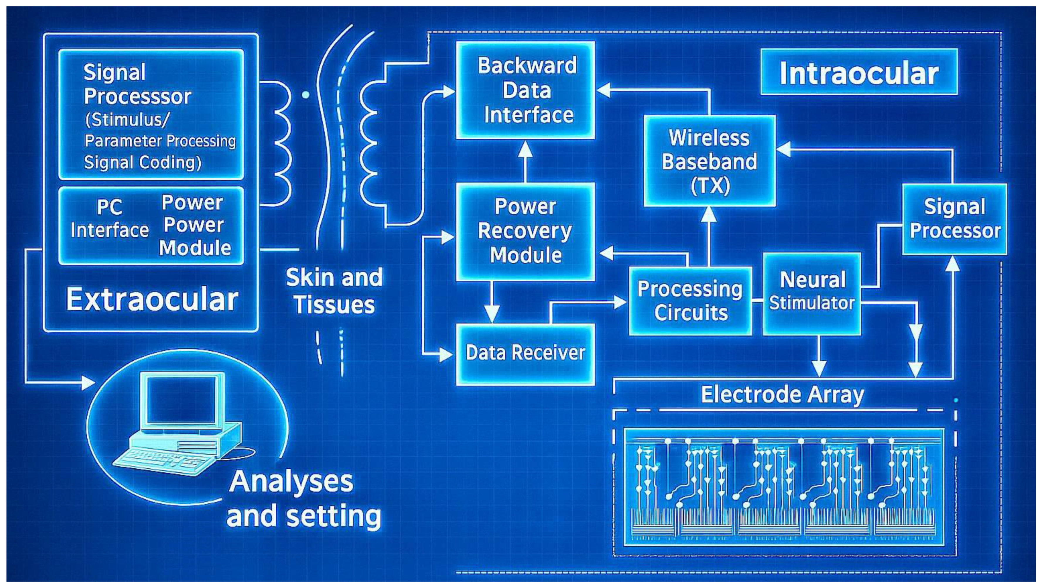
- Wireless power and data transmission: Modern retinal implants often use wireless power (e.g., inductive coupling) and telemetry to eliminate transcutaneous wires, a feature also seen in advanced ISTDs. This enables continuous operation without tethering the patient, but requires careful design to maintain reliability and safety.
- Electrode–retina distance: Minimizing the gap between electrodes and target neurons lowers the required stimulation threshold and enhances spatial resolution.
- Electrode size and geometry: Smaller electrodes offer higher spatial selectivity but may require higher current densities (raising risk of tissue damage), whereas larger electrodes deliver current over a broader area with lower density but reduce specificity.
- Charge density and pulse parameters: Safe stimulation mandates adhering to charge-injection limits to prevent electrode corrosion or tissue damage. Optimizing the pulse waveform (duration, amplitude, and frequency) is crucial for effective yet safe neural activation.
- Material biocompatibility: Electrodes must be made of materials that are biocompatible and capable of consistent electrical stimulation over years. Traditional materials like platinum and iridium oxide are the gold standards, and emerging alternatives like graphene are under investigation for their flexibility and conductivity.
4. Advances in Electrode Design
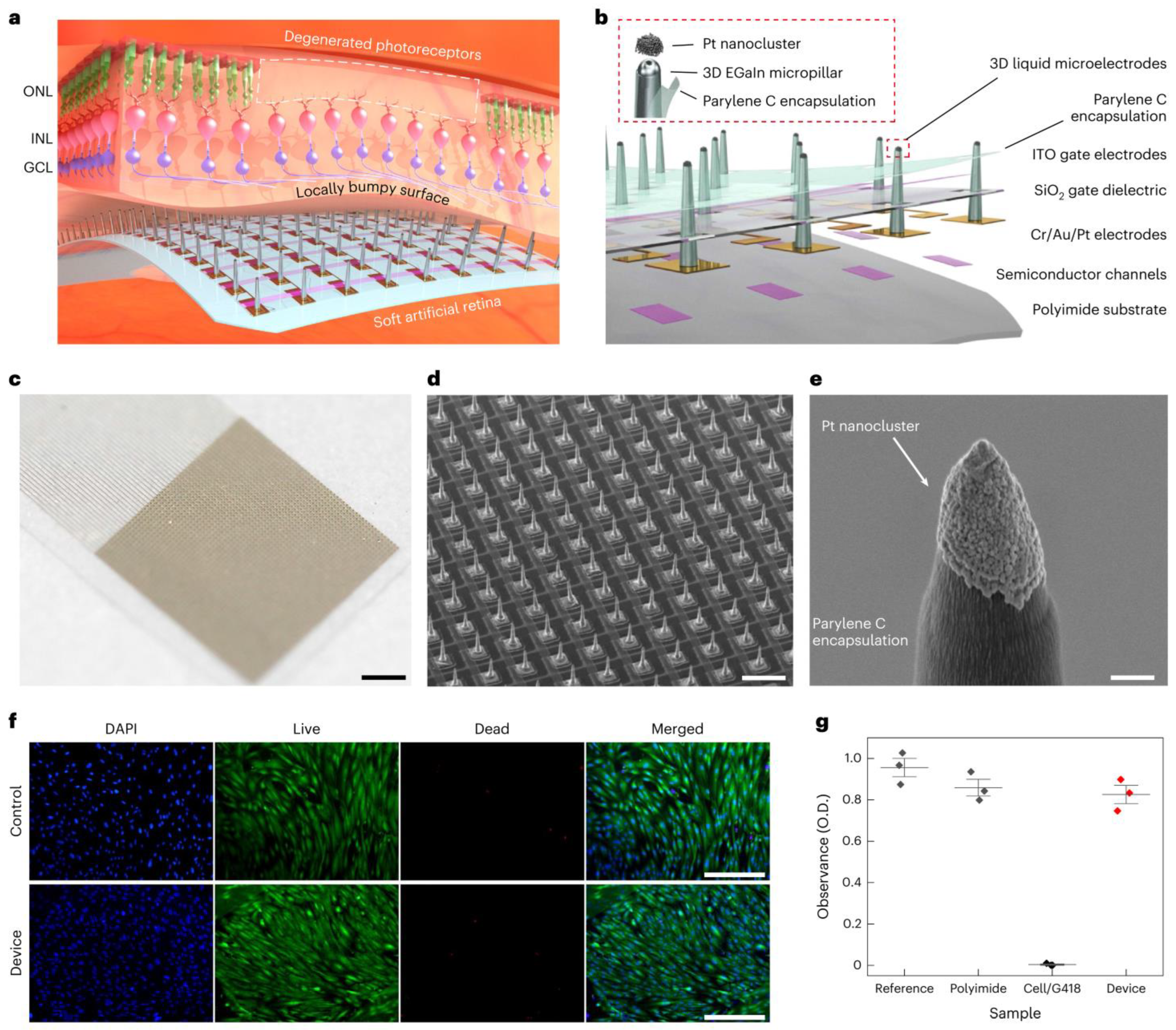
- Use of Novel Materials: The exploration of novel materials, such as graphene, has led to the development of electrodes that are not only both flexible and biocompatible, but also reduce the risks of mechanical damage to the retina and chronic immune responses. For instance, the incorporation of graphene (an ultra-thin, flexible carbon sheet) has led to electrodes that conform to tissue while maintaining excellent conductivity. Similarly, carbon nanotube (CNT) microelectrodes have shown promise—their high surface area and conductivity allow lower stimulation thresholds and intimate integration with neural tissue [74]. A cutting-edge development, detailed in a 2024 study, involves the use of soft, biocompatible liquid metals (LMs) such as eutectic gallium–indium alloy (EGaIn) for retinal electrodes [75]. As shown in Figure 4, these electrodes are integrated into an ultrathin (10-μm) artificial retina, combining flexible phototransistors with 3D micropillar electrodes. The electrodes are 3D micropillar arrays, with a height of 60 μm and diameter of 20 μm, scalable down to 5 μm. They are coated with platinum nanoclusters at the tips to enhance charge injection, achieving a charge storage capacity of 72.84 mC cm−2 and impedance of ~210 kΩ at 1 kHz. In vitro tests showed 82% cell viability, and in vivo tests in animal models revealed no inflammation or damage after 5 weeks, indicating suitability for long-term implantation. The major advantage of this development is the flexibility in minimizing the electrode–cell distance, reducing activation thresholds and improving spatial resolution. This design supports less invasive epiretinal implantation, potentially achieving 20/160 vision with high-resolution devices, a significant step toward functional vision restoration.
- Three-Dimensional Electrode Arrays: Advancements in microfabrication have enabled creation of 3D electrode geometries that better match the curvature and layered structure of the retina. Arrays of microscopic pillars or needles can penetrate or closely approach retinal neurons, ensuring consistent contact and effective stimulation. These 3D designs help minimize the electrode–retina distance (which is critical for lower thresholds and higher resolution). For example, a 2020 study introduced a subretinal 3D microelectrode array arranged in a hexagonal pattern to improve focal stimulation, as shown in Figure 5 [76]. This device used 98 pillar electrodes (150 μm diameter, ~20 μm high) on a flexible PDMS base, achieving a mean impedance of ~385 kΩ at 1 kHz and a charge storage capacity (CSC) of 2.83 mC·cm−2. This design aims to enhance visual acuity by reducing current dissipation and improving the activation of retinal cells. Such structured arrays demonstrated enhanced localization of stimulation and improved retinal cell activation compared to planar electrodes. A 2013 study highlights the use of liquid crystal polymer (LCP) for retinal electrodes, noted for its low moisture absorption compared to polyimide, Parylene, and silicone elastomers [77]. LCP is used in a novel retinal prosthetic device with monolithic encapsulation, integrating neural stimulation circuitries into a thin, eye-conformable structure. The study details electroplating for thickened metal tracks to improve mechanical strength and long-term reliability, enabled by high-pressure lamination. Laser machining, including laser ablation and laser thinning, enhances flexibility, particularly for the LCP electrode. A 2019 review also mentions the emerging field of tissue electronics using organic conductive/semi-conductive polymers, which offer more physiological interaction and potentially higher spatial resolution, fabricated using micromachining for precise patterning in terms of electrodes [78].
- Current Steering and Multiplexing: Implementing current steering strategies allows modulation of electric fields to stimulate target neurons selectively, without needing a one-to-one correspondence between electrodes and perceptual pixels. By dynamically controlling the distribution of current between neighboring electrodes, researchers can create “virtual” electrodes that effectively increase resolution. This can enhance spatial resolution without physically increasing the electrode count, mitigating some design and fabrication challenges. Current steering, along with multiplexing (time-sharing of electrodes), also helps manage power consumption and heat dissipation, which is crucial for devices with tens to hundreds of channels.
- Prosthetic Vision Simulation and Optimization: There is growing use of computational models and simulations of prosthetic vision to guide electrode layout. By simulating how a patient perceives patterns of stimulation, researchers can identify electrode configurations that maximize the visual field coverage or improve the clarity of perceived patterns. For example, recent studies employed algorithms (including AI-based approaches) to optimize electrode placement for better visual outcomes. These simulations inform design decisions, such as where to place higher density clusters of electrodes or how to arrange them to avoid interference, ultimately influencing hardware prototypes.

5. Comparative Properties of Electrode Materials
6. Encapsulation and Packaging Technology (Biocompatibility Considerations)
- Polyimide (PI): Polyimide offers superior thermal stability and mechanical strength, making it popular for flexible electronics and ribbon cables in implants [69,84]. It is moderately moisture-resistant but can still allow slow ingress; thus thin-film metal or ceramic coatings may be added for long-term hermeticity.
- Parylene C: This is a vacuum-deposited polymer coating that forms an ultra-thin conformal layer. Parylene-C has excellent biocompatibility and low permeability, making it useful as a coating on electronics. Its drawbacks are limited mechanical strength and potential cracking under flexing, but it is often used in combination with other encapsulation (e.g., a Parylene-coated device further encased in silicone) [85,86].
- Ceramics and Metals: Traditional hermetic packages (like those in pacemakers) use welded titanium cases or ceramic enclosures (e.g., alumina). These provide superb moisture barrier properties and long-term stability [82]. High-density ceramics such as alumina (Al2O3) and aluminum nitride (AlN) provide exceptional gas barrier properties and heat resistance, commonly used in long-term, high-reliability implantable devices [88]. Titanium, with its outstanding biocompatibility and mechanical strength, is a preferred material for traditional pacemaker and neurostimulator casings. However, its opacity and rigidity limit its use in applications requiring optical sensing or flexibility [88].
- Multilayer Encapsulation and Others: To overcome the limitations of single-material systems, multilayer encapsulation architectures—such as alternating silicon oxide/silicon nitride stacks or composites of Parylene with inorganic materials—are increasingly adopted, offering improved moisture resistance and mechanical protection [89]. Moreover, many modern implantables impose higher demands on the electromagnetic transparency and design flexibility of encapsulation materials [90]. MEMS and integrated encapsulation/packaging designs enable high-density integration and miniaturization through wafer-level packaging (WLP) and thin-film encapsulation techniques [91]. Laser bonding offers a high-precision, low-temperature process suitable for ceramic or glass encapsulation systems with stringent gas barrier requirements, commonly applied in retinal implants and high-density neural interfaces [92]. To systematically compare encapsulation approaches, Table 5 summarizes several encapsulation types and their advantages and disadvantages.
7. Conclusions and Future Directions
- Higher-density electrodes (possibly leveraging nanoscale features or 3D architectures to approach visual acuity in the ranges of legal blindness or better, e.g., 20/200 to 20/100);
- Advanced image processing (potentially AI-driven algorithms for feature enhancement, edge detection, and real-time adaptation to the environment and patient feedback);
- Improved materials (such as fully organic or hybrid materials that reduce foreign body response and last the lifetime of the patient without replacement);
- Modular or upgradable systems (for example, external components that can be improved without replacing the implant, as seen with some upgradeable vision prosthesis platforms).
Funding
Acknowledgments
Conflicts of Interest
References
- Hartong, D.T.; Berson, E.L.; Dryja, T.P. Retinitis pigmentosa. Lancet 2006, 368, 1795–1809. [Google Scholar] [CrossRef]
- De Jong, P.T.V.M. Age-related macular degeneration. N. Engl. J. Med. 2006, 355, 1474–1485. [Google Scholar] [CrossRef] [PubMed]
- Ferris, F.L.; Wilkinson, C.P.; Bird, A.; Chakravarthy, U.; Chew, E.; Csaky, K.; Sadda, S.R. Clinical classification of age-related macular degeneration. Ophthalmology 2013, 120, 844–851. [Google Scholar] [CrossRef]
- Daiger, S.P.; Bowne, S.J.; Sullivan, L.S. Genes and mutations causing retinitis pigmentosa. Clin. Genet. 2007, 72, 109–120. [Google Scholar] [CrossRef]
- Klein, R.; Klein, B.E.K.; Cruickshanks, K.J. The prevalence of age-related maculopathy by geographic region and ethnicity. Prog. Retin. Eye Res. 1999, 18, 371–389. [Google Scholar] [CrossRef]
- Hamel, C. Retinitis pigmentosa. Orphanet J. Rare Dis. 2006, 1, 40. [Google Scholar] [CrossRef] [PubMed]
- Ambati, J.; Fowler, B.J. Mechanisms of age-related macular degeneration. Neuron 2012, 75, 26–39. [Google Scholar] [CrossRef] [PubMed]
- Wright, A.F.; Chakarova, C.F.; Abd El-Aziz, M.M.; Bhattacharya, S.S. Photoreceptor degeneration: Genetic and mechanistic dissection of a complex trait. Nat. Rev. Genet. 2010, 11, 273–284. [Google Scholar] [CrossRef]
- Jager, R.D.; Mieler, W.F.; Miller, J.W. Age-related macular degeneration. N. Engl. J. Med. 2008, 358, 2606–2617. [Google Scholar] [CrossRef]
- Boughman, J.A.; Conneally, P.M.; Nance, W.E. Population genetic studies of retinitis pigmentosa. Am. J. Hum. Genet. 1980, 32, 223–235. [Google Scholar]
- Rizzo, J.F., III; Wyatt, J. Retinal prosthesis: An encouraging first step. Lancet 1998, 352, 1569–1570. [Google Scholar]
- Zrenner, E. Will retinal implants restore vision? Science 2002, 295, 1022–1025. [Google Scholar] [CrossRef]
- Chow, A.Y.; Chow, V.Y. Subretinal electrical stimulation of the rabbit retina. Neurosci. Lett. 1997, 225, 13–16. [Google Scholar] [CrossRef]
- Humayun, M.S.; Weiland, J.D.; Fujii, G.Y.; Greenberg, R.; Williamson, R.; Little, J.; Mech, B.; Cimmarusti, V.; Van Boemel, G.; Dagnelie, G.; et al. Visual perception in a blind subject with a chronic microelectronic retinal prosthesis. Vision Res. 2003, 43, 2573–2581. [Google Scholar] [CrossRef]
- Margalit, E.; Maia, M.; Weiland, J.D.; Greenberg, R.J.; Fujii, G.Y.; Torres, G.; Piyathaisere, D.V.; O’Hearn, T.M.; Liu, W.; Lazzi, G.; et al. Retinal prosthesis for the blind. Surv. Ophthalmol. 2002, 47, 335–356. [Google Scholar] [CrossRef]
- Weiland, J.D.; Liu, W.; Humayun, M.S. Retinal prosthesis. Annu. Rev. Biomed. Eng. 2005, 7, 361–401. [Google Scholar] [CrossRef]
- Chader, G.J.; Weiland, J.; Humayun, M.S. Artificial vision: Needs, functioning, and testing of a retinal electronic prosthesis. Prog. Brain Res. 2009, 175, 317–332. [Google Scholar]
- Stingl, K.; Bartz-Schmidt, K.U.; Besch, D.; Braun, A.; Bruckmann, A.; Gekeler, F.; Greppmaier, U.; Hipp, S.; Hörtdörfer, G.; Kernstock, C.; et al. Artificial vision with wirelessly powered subretinal electronic implant alpha-IMS. Proc. R. Soc. B 2013, 280, 20130077. [Google Scholar] [CrossRef]
- Luo, Y.H.-L.; da Cruz, L. The Argus® II retinal prosthesis system. Prog. Retin. Eye Res. 2016, 50, 89–107. [Google Scholar] [CrossRef]
- Palanker, D.; Vankov, A.; Huie, P.; Baccus, S. Design of a high-resolution optoelectronic retinal prosthesis. J. Neural Eng. 2005, 2, S105–S120. [Google Scholar] [CrossRef]
- Jepson, L.H.; Hottowy, P.; Mathieson, K.; Gunning, D.E.; Dąbrowski, W.; Litke, A.M.; Chichilnisky, E.J. Focal electrical stimulation of the retina with high-density, small-diameter electrode arrays. J. Neural Eng. 2013, 10, 035011. [Google Scholar]
- Jensen, R.J.; Rizzo, J.F. Activation of Retinal Ganglion Cells in Wild-Type and rd1 Mice through Electrical Stimulation of the Retinal Neural Network. Vision Res. 2008, 48, 1562–1568. [Google Scholar] [CrossRef] [PubMed]
- Sekirnjak, C.; Hottowy, P.; Sher, A.; Dabrowski, W.; Litke, A.M.; Chichilnisky, E.J. Electrical stimulation of mammalian retinal ganglion cells with multielectrode arrays. J. Neurophysiol. 2006, 95, 3311–3327. [Google Scholar] [CrossRef] [PubMed]
- Jensen, R.J.; Rizzo, J.F., III. Thresholds for activation of rabbit retinal ganglion cells with a subretinal electrode. Exp. Eye Res. 2006, 83, 367–373. [Google Scholar] [CrossRef]
- Jensen, R.J.; Ziv, O.R.; Rizzo, J.F., III. Responses of rabbit retinal ganglion cells to electrical stimulation with an epiretinal electrode. J. Neural Eng. 2005, 2, S16–S21. [Google Scholar] [CrossRef]
- Sekirnjak, C.; Hottowy, P.; Sher, A.; Dabrowski, W.; Litke, A.M.; Chichilnisky, E.J. High-resolution electrical stimulation of primate retina for epiretinal implant design. J. Neurosci. 2008, 28, 4446–4456. [Google Scholar] [CrossRef]
- Jensen, R.J.; Rizzo, J.F., III. Activation of retinal ganglion cells by selective electrical stimulation of the retina. Investig. Ophthalmol. Vis. Sci. 2007, 48, 1873–1880. [Google Scholar]
- Jensen, R.J.; Rizzo, J.F., III. Responses of ganglion cells to repetitive electrical stimulation of the retina. J. Neural Eng. 2007, 4, S1–S6. [Google Scholar] [CrossRef] [PubMed]
- Dorn, J.D.; Ahuja, A.K.; Caspi, A.; da Cruz, L.; Dagnelie, G.; Sahel, J.A.; Greenberg, R.J.; McMahon, M.J.; Humayun, M.S. The Detection of Motion by Blind Subjects with the Epiretinal 60-Electrode (Argus II) Retinal Prosthesis. Arch. Ophthalmol. 2013, 131, 183–189. [Google Scholar] [CrossRef]
- Rizzo, S.; Belting, C.; Cinelli, L.; Allegrini, L.; Genovesi-Ebert, F.; Barca, F.; Di Bartolo, E. The Argus II Retinal Prosthesis: 12-Month Outcomes from a Single-Study Center. Am. J. Ophthalmol. 2014, 157, 1282–1290.e1. [Google Scholar] [CrossRef]
- Da Cruz, L.; Coley, B.F.; Dorn, J.; Merlini, F.; Filley, E.; Christopher, P.; Chen, F.K.; Wuyyuru, V.; Sahel, J.A.; Stanga, P.; et al. The Argus II Epiretinal Prosthesis System Allows Letter and Word Reading and Long-Term Function in Patients with Profound Vision Loss. Br. J. Ophthalmol. 2013, 97, 632–636. [Google Scholar] [CrossRef]
- Muqit, M.M.K.; Le Mer, Y.; de Koo, L.O.; Holz, F.G.; Sahel, J.A.; Palanker, D. Prosthetic Visual Acuity with the PRIMA Subretinal Microchip in Patients with Atrophic Age-Related Macular Degeneration at 4 Years Follow-up. Ophthalmol. Sci. 2024, 4, 100217. [Google Scholar] [CrossRef] [PubMed]
- Palanker, D.; Le Mer, Y.; Muqit, M.M.K.; de Koo, L.O.; Sahel, J.A.; Galambos, P.; Mathieson, K.; Hoang, Q.V. Enhancing Prosthetic Vision by Upgrade of a Subretinal Photovoltaic Implant. Nat. Commun. 2025, 16, 58084. [Google Scholar]
- Mathieson, K.; Loudin, J.; Goetz, G.; Huie, P.; Wang, L.; Kamins, T.I.; Galambos, P.; Smith, R.; Harris, J.S.; Sher, A.; et al. Photovoltaic Retinal Prosthesis with High Pixel Density. Nat. Photonics 2012, 6, 391–397. [Google Scholar] [CrossRef] [PubMed]
- Zrenner, E.; Bartz-Schmidt, K.U.; Benav, H.; Besch, D.; Bruckmann, A.; Gabel, V.P.; Gekeler, F.; Greppmaier, U.; Harscher, A.; Kibbel, S.; et al. Subretinal Electronic Chips Allow Blind Patients to Read Letters and Combine Them to Words. Proc. Biol. Sci. 2011, 278, 1489–1497. [Google Scholar] [CrossRef] [PubMed]
- Lorach, H.; Goetz, G.; Mandel, Y.; Lei, X.; Kamins, T.I.; Mathieson, K.; Harris, J.S.; Palanker, D. Performance of Photovoltaic Arrays In-Vivo and Characteristics of Prosthetic Vision in Animals with Retinal Degeneration. Vis. Res. 2015, 111, 142–148. [Google Scholar] [CrossRef]
- Gong, C.-S.A. IC-Based Rectification Circuit Techniques for Biomedical Energy-Harvesting Applications. Micromachines 2022, 13, 411. [Google Scholar] [CrossRef]
- Chow, A.Y.; Pardue, M.T.; Chow, V.Y.; Peyman, G.A.; Liang, C.; Perlman, J.I.; Peachey, N.S. Implantation of Silicon Chip Microphotodiode Arrays into the Cat Subretinal Space. IEEE Trans. Neural Syst. Rehabil. Eng. 2001, 9, 86–95. [Google Scholar] [CrossRef]
- Zrenner, E.; Stett, A.; Weiss, S.; Aramant, R.B.; Guenther, E.; Kohler, K.; Miliczek, K.D.; Seiler, M.J.; Haemmerle, H. Can Subretinal Microphotodiodes Successfully Replace Degenerated Photoreceptors? Vision Res. 1999, 39, 2555–2567. [Google Scholar] [CrossRef]
- Humayun, M.S.; Prince, M.; de Juan, E.; Barron, Y.; Moskowitz, M.; Klock, I.B.; Milam, A.H. Morphometric Analysis of the Extramacular Retina from Postmortem Eyes with Retinitis Pigmentosa. Investig. Ophthalmol. Vis. Sci. 1999, 40, 143–148. [Google Scholar]
- Wang, L.; Mathieson, K.; Kamins, T.I.; Loudin, J.D.; Galambos, L.; Goetz, G.; Sher, A.; Mandel, Y.; Huie, P.; Lavinsky, D.; et al. Photovoltaic Retinal Prosthesis: Implant Fabrication and Performance. J. Neural Eng. 2012, 9, 046014. [Google Scholar] [CrossRef]
- Boinagrov, D.; Pangratz-Fuehrer, S.; Goetz, G.; Palanker, D. Selectivity of Direct and Network-Mediated Stimulation of the Retinal Ganglion Cells with Epi-, Sub- and Intraretinal Electrodes. J. Neural Eng. 2014, 11, 026008. [Google Scholar] [CrossRef] [PubMed]
- Edwards, T.L.; Cottriall, C.L.; Xue, K.; Simunovic, M.P.; Ramsden, J.D.; Zrenner, E.; MacLaren, R.E. Assessment of the Electronic Retinal Implant Alpha AMS in Restoring Vision to Blind Patients with End-Stage Retinitis Pigmentosa. Ophthalmology 2018, 125, 432–439. [Google Scholar] [CrossRef] [PubMed]
- Chuang, A.T.; Margo, C.E.; Greenberg, P.B. Retinal Implants: A Systematic Review. Br. J. Ophthalmol. 2014, 98, 852–856. [Google Scholar] [CrossRef]
- Goetz, G.A.; Palanker, D.V. Electronic Approaches to Restoration of Sight. Rep. Prog. Phys. 2016, 79, 096701. [Google Scholar] [CrossRef] [PubMed]
- Flores, T.; Lei, X.; Huang, T.; Lorach, H.; Dalal, R.; Galambos, L.; Kamins, T.; Mathieson, K.; Palanker, D. Optimization of Pillar Electrodes in Subretinal Prosthesis for Enhanced Proximity to Target Neurons. J. Neural Eng. 2018, 15, 036011. [Google Scholar] [CrossRef]
- Wang, B.Y.; Chen, Z.C.; Bhuckory, M.; Huang, T.; Shin, A.; Zuckerman, V.; Ho, E.; Rosenfeld, E.; Mathieson, K.; Palanker, D. Electronic Photoreceptors Enable Prosthetic Visual Acuity Matching the Natural Resolution in Rats. Nat. Commun. 2022, 13, 6627. [Google Scholar] [CrossRef]
- Gross, M.; Degenhart, A.; Goren, T.; Hendler, T.; Harel, D.; Minke, B.; Nelken, I.; Segev, R.; Weiss, A.; Yovel, G.; et al. A New High-Resolution Three-Dimensional Retinal Implant: System Design and Preliminary Human Results. bioRxiv 2022. [Google Scholar] [CrossRef]
- Ehrlich, R. Long-term Clinical Evaluation of Retinitis Pigmentosa (RP) Patients Implanted with A Novel Epiretinal Prosthetic Device—Interim Results. Floretina 2022. Available online: https://floretina.com/storage/abstractsbook/Abstract137.pdf (accessed on 1 May 2025).
- Asher, A.; Segal, W.A.; Baccus, S.A.; Yaroslavsky, L.; Palanker, D.V. Portable System for Photovoltaic Retinal Prosthesis with Real-Time Image Processing. Investig. Ophthalmol. Vis. Sci. 2009, 50, 3542–3548. [Google Scholar]
- Loudin, J.D.; Simanovskii, D.M.; Vijayraghavan, K.; Sramek, C.K.; Butterwick, A.F.; Huie, P.; McLean, G.Y.; Palanker, D.V. Optoelectronic Retinal Prosthesis: System Design and Performance. J. Neural Eng. 2007, 4, S72–S84. [Google Scholar] [CrossRef] [PubMed]
- Ghezzi, D.; Antognazza, M.R.; Dal Maschio, M.; Lanzarini, E.; Benfenati, F.; Lanzani, G. A Hybrid Bioorganic Interface for Neuronal Photoactivation. Nat. Commun. 2011, 2, 166. [Google Scholar] [CrossRef] [PubMed]
- Bareket, L.; Barriga-Rivera, A.; Suaning, G.J.; Lovell, N.H.; Hanein, Y. Progress in Artificial Vision Through Flexible Neural Interfaces. Adv. Mater. Technol. 2017, 2, 1700052. [Google Scholar]
- Ghaffari, R.; Rogers, J.A.; Nurmikko, A.V. Flexible Bioelectronics for Neural Interfaces: Materials and Devices for Brain-Computer Interfaces. Annu. Rev. Biomed. Eng. 2019, 21, 345–368. [Google Scholar]
- Chen, Z.; Wang, B.Y.; Bhuckory, M.; Kamins, T.I.; Palanker, D. High-Density Photovoltaic Retinal Prosthesis with Single-Cell Resolution. Sci. Adv. 2021, 7, eabj1113. [Google Scholar]
- Ho, E.; Huang, T.; Shin, A.; Zuckerman, V.; Mathieson, K.; Palanker, D. Advances in Electrode Design for Enhanced Retinal Prosthetic Resolution. J. Neural Eng. 2023, 20, 046021. [Google Scholar]
- Barak, A.; Stalmans, P.; Rizzo, S.; Ehrlich, R. The NR600 Retinal Prosthesis: Preliminary Safety and Efficacy Results from a Multi-Center Clinical Trial. Ophthalmic Res. 2024, 67, 245–253. [Google Scholar]
- Butterwick, A.; Huie, P.; Jones, B.W.; Marc, R.E.; Marmor, M.; Palanker, D. Effect of Shape and Coating of a Subretinal Prosthesis on Its Integration with the Retina. Exp. Eye Res. 2009, 88, 22–29. [Google Scholar] [CrossRef]
- Mandel, Y.; Goetz, G.; Lavinsky, D.; Huie, P.; Mathieson, K.; Wang, L.; Kamins, T.; Manivanh, R.; Harris, J.S.; Palanker, D. Cortical Responses Elicited by Photovoltaic Subretinal Prostheses Exhibit High Spatial Resolution. Nat. Commun. 2013, 4, 1980. [Google Scholar] [CrossRef]
- Bhuckory, M.B.; Wang, B.Y.; Chen, Z.C.; Shin, A.; Huang, T.; Galambos, L.; Vounotrypidis, E.; Mathieson, K.; Kamins, T.; Palanker, D. 3D Electronic Scaffolds for Restoration of Visual Acuity in Rats with Retinal Degeneration. Sci. Transl. Med. 2021, 13, eabb9111. [Google Scholar]
- Ferlauto, L.; AiraghiLeccardi, M.J.I.; Chenais, N.A.L.; Gilliéron, S.C.A.; Vagni, P.; Bevilacqua, M.; Wolfensberger, T.J.; Sivula, K.; Ghezzi, D. A Fully Organic Retinal Prosthesis Restores Vision in a Rat Model of Degenerative Blindness. Nat. Mater. 2018, 17, 460–468. [Google Scholar]
- Tandon, P.; Chen, Z.; Ferreira, J.; Palanker, D.; Mitra, S. Optimizing Photovoltaic Retinal Prosthesis Using Conditional Invertible Neural Networks. IEEE Trans. Biomed. Eng. 2023, 70, 2156–2165. [Google Scholar]
- Lee, S.; Wang, B.Y.; Bhuckory, M.; Palanker, D.; Mitra, S. Greedy Optimization of Electrode Placement for Retinal Prostheses Improves Visual Outcomes in Simulations. J. Neural Eng. 2024, 21, 026013. [Google Scholar]
- Jeong, J.; Bae, S.H.; Min, K.S.; Seo, J.M.; Chung, H.; Kim, S.J. A miniaturized, eye-conformable, and long-term reliable retinal prosthesis using monolithic fabrication of liquid crystal polymer (LCP). IEEE Trans. Biomed. Eng. 2015, 62, 982–989. [Google Scholar] [CrossRef] [PubMed]
- Kim, J.; Lee, M.; Shim, H.J.; Ghaffari, R.; Cho, H.R.; Son, D.; Jung, Y.H.; Soh, M.; Choi, C.; Jung, S.; et al. Stretchable silicon nanoribbon electronics for skin prosthesis. Nat. Commun. 2014, 5, 5747. [Google Scholar] [CrossRef] [PubMed]
- Park, S.I.; Brenner, D.S.; Shin, G.; Morgan, C.D.; Copits, B.A.; Chung, H.U.; Pullen, M.Y.; Noh, K.N.; Davidson, S.; Oh, S.J.; et al. Soft, stretchable, fully implantable miniaturized optoelectronic systems for wireless optogenetics. Nat. Biotechnol. 2015, 33, 1280–1286. [Google Scholar] [CrossRef]
- Kim, T.; Lee, S.; Chen, Z.; Palanker, D.; Lee, H. Liquid metal-based soft electronics for a fully implantable retinal prosthesis. Sci. Adv. 2023, 9, eadh0315. [Google Scholar]
- Wise, K.D.; Anderson, D.J.; Hetke, J.F.; Kipke, D.R.; Najafi, K. Wireless implantable microsystems: High-density electronic interfaces to the nervous system. Proc. IEEE 2004, 92, 76–97. [Google Scholar] [CrossRef]
- Cheung, K.C.; Renaud, P.; Tanila, H.; Djupsund, K. Flexible polyimide microelectrode array for in vivo recordings and current source density analysis. Biosens. Bioelectron. 2007, 22, 1783–1790. [Google Scholar] [CrossRef]
- Rodger, D.C.; Weiland, J.D.; Humayun, M.S.; Tai, Y.C. Scalable high lead-count parylene package for retinal prostheses using three-dimensional micromachining. Sens. Actuators B Chem. 2006, 117, 107–114. [Google Scholar] [CrossRef]
- Tooker, A.; Tolosa, V.; Shah, K.G.; Sheth, H.; Felix, S.; Delima, T.; Pannu, S. Polymer neural interface with dual-sided electrodes fabricated using high aspect ratio DRIE and laser micromachining. J. Microelectromech. Syst. 2012, 21, 1212–1221. [Google Scholar]
- Ayton, L.N.; Barnes, N.; Dagnelie, G.; Fujikado, T.; Goetz, G.; Hornig, R.; Stingl, K.; Shivdasani, M.N.; Vision Processing Committee of the International Consortium for Visual Prostheses. An update on retinal prostheses. Clin. Neurophysiol. 2020, 131, 1383–1398. [Google Scholar] [CrossRef]
- Stronks, H.C.; Dagnelie, G. The functional performance of the Argus II retinal prosthesis. Expert Rev. Med. Devices 2014, 11, 23–30. [Google Scholar] [CrossRef]
- Eleftheriou, C.G.; Zimmermann, J.B.; Kjeldsen, H.D.; David-Pur, M.; Hanein, Y.; Sernagor, E. Carbon nanotube electrodes for retinal implants: A study of structural and functional integration over time. Biomaterials 2017, 112, 108–121. [Google Scholar] [CrossRef]
- Chung, W.G.; Jang, J.; Cui, G.; Lee, S.; Jeong, H.; Kang, H.; Seo, H.; Kim, S.; Kim, E.; Lee, J.; et al. Liquid-metal-based three-dimensional microelectrode arrays integrated with implantable ultrathin retinal prosthesis for vision restoration. Nat. Nanotechnol. 2024, 19, 688–697. [Google Scholar] [CrossRef]
- Seo, H.W.; Kim, N.; Kim, S. Fabrication of Subretinal 3D Microelectrodes with Hexagonal Arrangement. Micromachines 2020, 11, 467. [Google Scholar] [CrossRef]
- Jeong, J.; Shin, S.; Lee, G.J.; Gwon, T.M.; Park, J.H.; Kim, S.J. Advancements in fabrication process of microelectrode array for a retinal prosthesis using Liquid Crystal Polymer (LCP). In Proceedings of the 2013 35th Annual International Conference of the IEEE Engineering in Medicine and Biology Society (EMBC), Osaka, Japan, 3–7 July 2013; pp. 5295–5298. [Google Scholar]
- Bloch, E.; Luo, Y.; da Cruz, L. Advances in retinal prosthesis systems. Ther. Adv. Ophthalmol. 2019, 11, 2515841418817501. [Google Scholar] [CrossRef]
- Cogan, S.F. Neural stimulation and recording electrodes. Annu. Rev. Biomed. Eng. 2008, 10, 275–309. [Google Scholar] [CrossRef]
- Najafi, K. Packaging of Implantable Microsystems. In Proceedings of the IEEE Sensors Conference, Atlanta, GA, USA, 28–31 October 2007; pp. 28–31. [Google Scholar]
- Stieglitz, T.; Beutel, H.; Meyer, J.-U. “Microflex”—A new assembling technique for interconnects. J. Micromech. Microeng. 2000, 10, 186–190. [Google Scholar]
- Weiland, J.D.; Anderson, D.J.; Humayun, M.S. In vitro biocompatibility of materials for a retinal prosthesis. J. Biomed. Mater. Res. 2000, 51, 366–373. [Google Scholar]
- Charkhkar, H.; Knaack, G.L.; McHail, D.G.; Mandal, H.S.; Peixoto, N.; Rubinson, J.F.; Dumas, T.C.; Pancrazio, J.J. Chronic intracortical neural recordings using thin-film parylene-c substrate. IEEE Trans. Neural Syst. Rehabil. Eng. 2017, 25, 1–10. [Google Scholar]
- Rousche, P.J.; Pellinen, D.S.; Pivin, D.P.; Williams, J.C.; Vetter, R.J.; Kipke, D.R. Flexible polyimide-based intracortical electrode arrays with bioactive capability. IEEE Trans. Biomed. Eng. 2001, 48, 361–371. [Google Scholar] [CrossRef] [PubMed]
- Hassler, C.; von Metzen, R.P.; Ruther, P.; Stieglitz, T. Characterization of parylene C as an encapsulation material for implanted neural prostheses. J. Biomed. Mater. Res. B Appl. Biomater. 2011, 93, 266–274. [Google Scholar] [CrossRef]
- Zhou, D.D.; Greenbaum, E. Implantable neural prostheses. Annu. Rev. Biomed. Eng. 2009, 11, 1–24. [Google Scholar]
- Anderson, J.M.; Rodriguez, A.; Chang, D.T. Foreign body reaction to biomaterials. Semin. Immunol. 2008, 20, 86–100. [Google Scholar] [CrossRef]
- Fang, H.; Zhao, J.; Yu, K.J.; Song, E.; Farimani, A.B.; Chiang, C.H.; Jin, X.; Xue, Y.; Xu, D.; Du, W.; et al. Ultrathin, transferred layers of thermally grown silicon dioxide as biofluid barriers for biointegrated flexible electronic systems. Proc. Natl. Acad. Sci. USA 2016, 113, 11682–11687. [Google Scholar] [CrossRef]
- Harrison, R.R. The design of integrated circuits to observe brain activity. Proc. IEEE 2008, 96, 1203–1216. [Google Scholar] [CrossRef]
- Mukherjee, D.; Rainu, S.K.; Singh, N.; Mallick, D. A Miniaturized, Low-Frequency Magnetoelectric Wireless Power Transfer System for Powering Biomedical Implants. IEEE Trans. Biomed. Circuits Syst. 2024, 18, 438–450. [Google Scholar] [CrossRef]
- Torunbalci, M.M.; Alper, S.E.; Akin, T. Wafer Level Hermetic Sealing of MEMS Devices with Vertical Feedthroughs Using Anodic Bonding. Sensors Actuators A Phys. 2015, 224, 169–176. [Google Scholar] [CrossRef]
- Kim, D.H.; Lu, N.; Ma, R.; Kim, Y.S.; Kim, R.H.; Wang, S.; Wu, J.; Won, S.M.; Tao, H.; Islam, A.; et al. Epidermal electronics. Science 2011, 333, 838–843. [Google Scholar] [CrossRef]
- Li, C.; Cauwe, M.; Yang, Y.; Schaubroeck, D.; Mader, L.; Op de Beeck, M. Ultra-Long-Term Reliable Encapsulation Using an Atomic Layer Deposited HfO2/Al2O3/HfO2 Triple-Interlayer for Biomedical Implants. Coatings 2019, 9, 579. [Google Scholar] [CrossRef]
- Hwang, S.W.; Tao, H.; Kim, D.H.; Cheng, H.; Song, J.K.; Rill, E.; Brenckle, M.A.; Panilaitis, B.; Won, S.M.; Kim, Y.S.; et al. A physically transient form of silicon electronics. Science 2012, 337, 1640–1644. [Google Scholar] [CrossRef] [PubMed]
- Cui, X.; Lee, V.A.; Raphael, Y.; Wiler, J.A.; Hetke, J.F.; Anderson, D.J.; Martin, D.C. Surface modification of neural recording electrodes with conducting polymer/biomolecule blends. J. Biomed. Mater. Res. 2001, 56, 261–272. [Google Scholar] [CrossRef]
- Ding, J.; Zeng, M.; Tian, Y.; Chen, Z.; Qiao, Z.; Xiao, Z.; Wu, C.; Wei, D.; Sun, J.; Fan, H. Flexible Silk-Fibroin-Based Microelectrode Arrays for High-Resolution Neural Recording. Mater. Horiz. 2024, 11, 4338–4347. [Google Scholar] [CrossRef]
- Koh, A.; Kang, D.; Xue, Y.; Lee, S.; Pielak, R.M.; Kim, J.; Hwang, T.; Min, S.; Banks, A.; Rogers, J.A. A Soft, Wearable Microfluidic Device for the Capture, Storage, and Colorimetric Sensing of Sweat. Sci. Transl. Med. 2016, 8, 366ra165. [Google Scholar] [CrossRef]
- Sreejith, S.; Leo Joseph, L.M.I.; Kollem, S.; Vijumon, V.T.; Ajayan, J. Biodegradable Sensors: A Comprehensive Review. Measurement 2023, 219, 113261. [Google Scholar] [CrossRef]
- Jeong, J.W.; Shin, G.; Park, S.I.; Yu, K.J.; Xu, L.; Rogers, J.A. Soft materials in neuroengineering for hard problems in neuroscience. Neuron 2015, 86, 175–186. [Google Scholar] [CrossRef] [PubMed]
- Fu, R.; Luo, W.; Nazempour, R.; Tan, D.; Ding, H.; Zhang, K.; Yin, L.; Guan, J.; Sheng, X. Implantable and Biodegradable Poly(L-Lactic Acid) Fibers for Optical Neural Interfaces. Adv. Opt. Mater. 2017, 6, 1700941. [Google Scholar] [CrossRef]
- Iqbal, A.; Al-Hasan, M.; Mabrouk, I.B.; Basir, A.; Nedil, M.; Yoo, H. Biotelemetry and Wireless Powering of Biomedical Implants Using a Rectifier Integrated Self-Diplexing Implantable Antenna. IEEE Trans. Microw. Theory Tech. 2021, 69, 3438–3451. [Google Scholar] [CrossRef]
- Buchwalder, S.; Nicolier, C.; Hersberger, M.; Bourgeois, F.; Hogg, A.; Burger, J. Development of a Water Transmission Rate (WTR) Measurement System for Implantable Barrier Coatings. Polymers 2023, 15, 2557. [Google Scholar] [CrossRef]
- Barrese, J.C.; Rao, N.; Paroo, K.; Triebwasser, C.; Vargas-Irwin, C.; Franquemont, L.; Donoghue, J.P. Failure mode analysis of silicon-based intracortical microelectrode arrays in non-human primates. J. Neural Eng. 2013, 10, 066014. [Google Scholar] [CrossRef] [PubMed]
- Fallegger, F.; Trouillet, A.; Lacour, S.P. Subdural Soft Electrocorticography (ECoG) Array Implantation and Long-Term Cortical Recording in Minipigs. J. Vis. Exp. 2023, 193, e64997. [Google Scholar] [CrossRef] [PubMed]
- Hossain, N.; Al Mahmud, M.Z.; Hossain, A.; Rahman, M.K.; Islam, M.S.; Tasnim, R.; Mobarak, M.H. Advances of materials science in MEMS applications: A review. Results Eng. 2024, 22, 102115. [Google Scholar] [CrossRef]
- Ahn, S.H.; Jeong, J.; Kim, S.J. Emerging Encapsulation Technologies for Long-Term Reliability of Microfabricated Implantable Devices. Micromachines 2019, 31, 10. [Google Scholar] [CrossRef] [PubMed]
- Jurak, M.; Wiącek, A.E.; Ładniak, A.; Przykaza, K.; Szafran, K. What affects the biocompatibility of polymers? Adv. Colloid Interface Sci. 2021, 294, 102451. [Google Scholar] [CrossRef]
- Eggenberger, S.C.; James, N.L.; Ho, C.; Eamegdool, S.S.; Tatarinoff, V.; Craig, N.A.; Gow, B.S.; Wan, S.; Dodds, C.W.D.; La Hood, D.; et al. Implantation and long-term assessment of the stability and biocompatibility of a novel 98 channel suprachoroidal visual prosthesis in sheep. Biomaterials 2021, 279, 121191. [Google Scholar] [CrossRef]
- Spicer, J.B.; Kang, J.; Patterson, A.L.; Boctor, E.M. Polymer Matrix Nanocomposites as Photoacoustic Transmitters for Epiretinal Prosthetics. In Proceedings of the 2023 IEEE 23rd International Conference on Nanotechnology (NANO), Jeju City, Republic of Korea, 2–5 August 2023; pp. 133–136. [Google Scholar]
- Nguyen, D.; Valet, M.; Dégardin, J.; Boucherit, L.; Illa, X.; de la Cruz, J.; del Corro, E.; Bousquet, J.; Garrido, J.A.; Hébert, C.; et al. Novel graphene electrode for retinal implants: An in vivo biocompatibility study. Front. Neurosci. 2021, 15, 615256. [Google Scholar] [CrossRef]


| Feature | Subretinal Implants | Epiretinal Implants |
| Target Cells | Bipolar cells | Ganglion cells |
| Electrode Placement | Beneath the retina (subretinal space) | On the retinal surface (vitreal side) |
| Power Source | Photovoltaic (light-powered) or wired (transocular cable) | External power (wireless induction or batteries in glasses unit) |
| Surgical Complexity | More invasive (retinal detachment and subretinal insertion) | Less invasive (device affixed to retinal surface) |
| Image Processing | Intrinsic retinal processing (implant directly uses light input) | External camera-based processing (real-time video feed) |
| Resolution Potential | Higher (finer pixel pitch possible, uses residual neural network) | Lower (limited by electrode count and size) |
| Adaptability | Limited adjustability post-implantation (fixed electronics) | Adjustable via external controls (camera and processor tunable) |
| Advantages |
|
|
| Challenges |
|
|
| Reference | Main Contribution | Advantages | Disadvantages | Placement Position of Electrode | Year |
|---|---|---|---|---|---|
| Chow et al., IEEE TNSRE [38] | Implanted silicon microphotodiode arrays in subretinal space (cat model). | Demonstrated biocompatibility and photodiode function in vivo. | Limited resolution; preclinical animal study (no human data). | Subretinal | 2001 |
| Zrenner et al., Vision Res. [39] | Explored subretinal microphotodiodes to replace lost photoreceptors. | Validated theoretical feasibility of subretinal implants. | Lacked functional validation in humans (concept study). | Subretinal | 1999 |
| Humayun et al., IOVS [40] | Morphometric analysis of postmortem RP patient retinas (no implant). | Provided anatomical insights for implant design (e.g., cell counts, spacing). | No implant tested—study of retinal structure only. | N/A (anatomy) | 1999 |
| Wang et al., J. Neural Eng. [41] | Photovoltaic retinal prosthesis: implant fabrication and performance (in vitro/in vivo tests). | Compact design; completely wireless operation. | Requires high-intensity illumination; tested in animals (preclinical). | Subretinal | 2012 |
| Boinagrov et al., J. Neural Eng. [42] | Compared stimulation selectivity of epi-, sub-, and intraretinal electrodes (computational and in vitro). | Detailed comparison of three placements; identified trade-offs in activating neural networks. | Theoretical/experimental study—not a clinical trial. | Epi-, Sub-, and Intra- | 2014 |
| Edwards et al., Ophthalmology [43] | Alpha AMS subretinal implant clinical trial in end-stage RP patients. | Showed partial restoration of visual perception in blind patients (light localization, object detection). | Limited field of view and modest resolution (approx. 1500 pixel implant). | Subretinal | 2018 |
| Chuang et al., Br. J. Ophthalmol. [44] | Systematic review of retinal implants (pre-2014 literature). | Summarized clinical and preclinical findings across studies. | No new experimental data (literature review). | Various | 2014 |
| Goetz & Palanker, Rep. Prog. Phys. [45] | Comprehensive technical review of electronic vision restoration approaches. | Provided broad overview with engineering insights. | Theoretical perspective, no new experiments (review). | Various | 2016 |
| Flores et al., J. Neural Eng. [46] | Optimized pillar electrode design for subretinal implants (in vitro study). | Enhanced proximity of electrodes to target neurons, improving stimulation efficacy. | Still in experimental phase (no human implantation yet). | Subretinal | 2018 |
| Wang et al., Nat. Commun. [47] | Demonstrated prosthetic vision matching natural acuity in rats (using a high-resolution subretinal optoelectronic implant). | Achieved near-natural resolution in an animal model (a significant milestone in acuity). | Preclinical results only; no human trials yet conducted. | Subretinal | 2022 |
| Advance (Year) | Electrode Design Details | Fabrication Techniques | Key Findings/Metrics |
|---|---|---|---|
| Soft Liquid–Metal Electrodes (2024) | Ultrathin (10 μm) flexible artificial retina with embedded eutectic Ga-In (EGaIn) liquid-metal microelectrodes (3D micropillars: 60 μm height, 20 μm diameter, Pt-nanocluster coated tips). | 3D printing of micro-molds; pneumatic microfluidic filling of liquid metal; six-axis laser micromachining of electrode array. | High charge capacity (72.8 mC·cm−2) and low impedance (~210 kΩ at 1 kHz) achieved. In vitro: 82% cell viability; in vivo (rat) showed no inflammation at 5 weeks. Predicted visual acuity ~20/160 with high-density configuration. |
| Hexagonal 3D Pillar Array (2020) | Flexible PDMS-based array with 98 circular silicon pillar electrodes (150 μm diameter, 350 μm pitch, ~20 μm protrusion). Parylene-C insulation except at tips, platinum-coated. | Deep reactive ion etching (DRIE); chemical etching and elastic PDMS press; metal sputtering (Ti/Pt). | Impedance ~385 kΩ (1 kHz), CSC 2.83 mC·cm−2. Enhanced localized stimulation of retinal cells with reduced current spread. Demonstrated improved targeting of retinal neurons in vitro. |
| Monolithic LCP-Based Prosthesis (2013) | LCP microelectrode array with integrated circuitry. Thickened metal tracks; electrode sites laser-patterned. | High-pressure lamination; electroplating of gold conductors; laser ablation; monolithic encapsulation. | Achieved long-term stability in aging tests. Low moisture uptake. Improved mechanical reliability over polyimide or silicone-based arrays. |
| “Artificial Retina” Review (2019) | Survey of emerging concepts including organic polymer electrodes and 3D tissue-integrated electronics. | – (n/a, literature review) – | Reported novel approaches like conductive polymer electrodes and 3D structured electrodes. Emphasized micromachining for precise electrode patterning. |
| Intraretinal 3D Electrodes—NR600 (2024) | Intraretinal electrode array (~600 microelectrodes) placed within retina to stimulate neurons in multiple layers. | Custom 3D array fabrication; proprietary assembly; hermetic packaging. | Preliminary clinical results: Safe implantation in late-stage RP patients. Elicited finer phosphenes. Improved spatial resolution and contrast (early trial). |
| Material | Advantages | Disadvantages | Usage in Retinal Prostheses |
|---|---|---|---|
| Platinum (Pt) | Excellent biocompatibility; highly stable and corrosion-resistant; decades of use in implants. | Rigid (high modulus)—not flexible; relatively low surface area (unless textured); moderate charge injection limit. | Standard electrode material in most implants (e.g., Argus II uses Pt electrodes). Often used as base material due to reliability. |
| Iridium Oxide (IrOx) | Very high charge injection capacity (can deliver more charge without damage); forms capacitive, low-impedance interface when activated. | Brittle as a bulk material; requires activation/forming process; can dissolve or delaminate if overstressed over long term. | Used in some high-density arrays and penetrating electrodes to increase charge delivery (e.g., in experimental high-resolution electrode arrays). Common in lab prototypes needing low impedance. |
| Graphene | Ultra-thin and flexible; can be transparent; high electrical conductivity; large surface-to-volume ratio (potential for high charge storage). | New and relatively unproven long-term in vivo; challenges in making reliable electrical contacts; can be sensitive to defects (which may impact stability). | Investigated in recent research for flexible retinal electrodes and transparent electronics. Not yet in clinical devices, but promising for future microfabricated arrays that conform to retina. |
| Carbon Nanotubes (CNTs) | Extremely high surface area (greatly lowers impedance and stimulation threshold); good biocompatibility when purified; can form flexible, porous coatings on electrodes. | Difficult to pattern uniformly; risk of aggregation or fragmentation of nanotubes over time; long-term stability and integration still under study. | Used experimentally as coatings on metal electrodes to improve interface (e.g., lowering thresholds in animal tests). Showed that CNT-coated electrodes can integrate with retinal tissue over days, reducing threshold with time. Not yet in commercial devices. |
| Conductive Polymers (e.g., PEDOT:PSS) | Soft, tissue-like mechanical properties (minimizes foreign body reaction); can dramatically lower impedance; can be deposited on microelectrodes to improve charge transfer. | Prone to delamination or degradation in the body (swelling, cracking over months); limited operational lifetime if not encapsulated; some variants may leach by-products. | Being explored for ‘living electrodes’ that better integrate with neural tissue. PEDOT-coated electrodes in research have shown lower stimulation thresholds. Fully organic retinal implants (conducting polymer-based photodiodes) restored vision in rat models, though not yet in human trials. |
| Encapsulation Type | Description | Advantages | Disadvantages |
|---|---|---|---|
| Thin Silicone Coating | Device components encased in medical-grade silicone (PDMS). | Very flexible; cushions device and dampens mechanical strain. Easy to apply. | Poor moisture/gas barrier (requires extra sealing layers); may allow slow fluid ingress → long-term failure if used alone. |
| Parylene-C Conformal Coating | Pinhole-free polymer film (µm-scale) vapor-deposited over device. | Excellent conformality, covering complex shapes; low permeability to moisture in short term; adds negligible thickness. | Brittle under repeated flexing; microcracks can form over time, compromising seal. Often used as secondary coating with other encapsulation. |
| Thin-Film Multilayer (Polymer + Oxide) | Stacks of alternating polymer and inorganic (oxide or nitride) layers. Example: polyimide plus silicon oxide layers. | Good barrier properties by complementary layers (polymer gives flexibility, oxide gives hermetic seal). Still relatively thin and flexible. | Fabrication can be complex; any pinhole in inorganic layer can let moisture in (hence, multiple layers needed). Long-term reliability under flex not fully proven. |
| Ceramic Package (e.g., Alumina or Glass) | Rigid case enclosing electronics, often brazed or bonded to metal feedthroughs. | Truly hermetic (virtually no moisture ingress); decades-long track record in implants (e.g., cochlear implants). Biocompatible and corrosion-proof. | Rigid and can be bulky relative to eye anatomy; requires precise assembly of feedthroughs; expensive fabrication. |
| Metal Case (Titanium or Stainless Steel) | Seam-welded metal can enclosing entire implant electronics, with electrode array fed through sealed connector. | Hermetic and extremely durable (titanium is biocompatible and an industry standard for hermetic implants). Excellent shielding of electronics. | Bulk and rigidity; not suitable for micro-scale or flexible retinal implants (would significantly limit conformability to eye). Also heavy. |
| Monolithic Encapsulation (LCP or Epoxy Housing) | Electronics embedded within a single-piece molded biocompatible material (like liquid crystal polymer) that acts as both circuit substrate and enclosure. | Fewer assembly steps (integrated solution); LCP in particular has very low moisture absorption and can be thermoformed to eye shape. Can be thin and conformable. | Achieving hermetic seals at contacts is challenging; some polymers still allow slight moisture ingress. |
| Reference | Main Contribution | Advantages | Disadvantages | Application | Year |
|---|---|---|---|---|---|
| Cui et al. | Surface modification of neural electrodes with polymer/biomolecule blends | Improved biocompatibility and electrical interface | Potential degradation of coatings over time | Neural recording [95] | 2001 |
| Ding et al. | Flexible microelectrode arrays | Long-term stability, good neuronal interface | Complex microfabrication process | Chronic neuronal recording (cortex) [96] | 2024 |
| Koh et al. | Wearable microfluidic sweat sensors | Soft, flexible sensing | Low integration with rigid electronics (applicable more to wearables) | Wearable biosensing [97] | 2016 |
| Sreejith et al. | Biodegradable sensors for intracranial monitoring | Full biodegradability | Short operational lifespan | Brain pressure and temperature sensing…, etc. [98] | 2023 |
| Jeong et al. | Soft materials in neuroengineering | High compliance with tissue | Fabrication challenges | General neuroengineering applications [99] | 2015 |
| Fu et al. | Biodegradable optical fibers | Biocompatible light delivery | Limited transmission performance | Photomedicine [100] | 2017 |
| Hassler et al. | Parylene C characterization | Stable, low-permeability coating | Limited mechanical durability | Neural prosthesis encapsulation [85] | 2011 |
| Barrese et al. | Failure analysis of microelectrode arrays | Detailed mode identification | Silicon fragility | Intracortical electrodes [103] | 2013 |
| Fallegger et al. | Soft lithographic flexible interface | Good adaptability to cortex | Integration and alignment issues | Wireless BMIs [104] | 2023 |
| Hossain et al. | MEMS-enabled devices | Miniaturized systems | Packaging and power supply concerns | Implantable sensors [105] | 2020 |
| Ahn et al. | Comprehensive review of encapsulation | Covers multiple techniques | No novel experimental data | Reference for future designs [106] | 2019 |
Disclaimer/Publisher’s Note: The statements, opinions and data contained in all publications are solely those of the individual author(s) and contributor(s) and not of MDPI and/or the editor(s). MDPI and/or the editor(s) disclaim responsibility for any injury to people or property resulting from any ideas, methods, instructions or products referred to in the content. |
© 2025 by the author. Licensee MDPI, Basel, Switzerland. This article is an open access article distributed under the terms and conditions of the Creative Commons Attribution (CC BY) license (https://creativecommons.org/licenses/by/4.0/).
Share and Cite
Gong, C.-S. Advances in Electrode Design and Physiological Considerations for Retinal Implants. Micromachines 2025, 16, 598. https://doi.org/10.3390/mi16050598
Gong C-S. Advances in Electrode Design and Physiological Considerations for Retinal Implants. Micromachines. 2025; 16(5):598. https://doi.org/10.3390/mi16050598
Chicago/Turabian StyleGong, Cihun-Siyong. 2025. "Advances in Electrode Design and Physiological Considerations for Retinal Implants" Micromachines 16, no. 5: 598. https://doi.org/10.3390/mi16050598
APA StyleGong, C.-S. (2025). Advances in Electrode Design and Physiological Considerations for Retinal Implants. Micromachines, 16(5), 598. https://doi.org/10.3390/mi16050598