

High-Temperature Properties of LP-DED Additive Manufactured Ferritic STS 430 Deposits on Martensitic STS 410 Base Metal


Abstract
1. Introduction
2. Materials and Methods
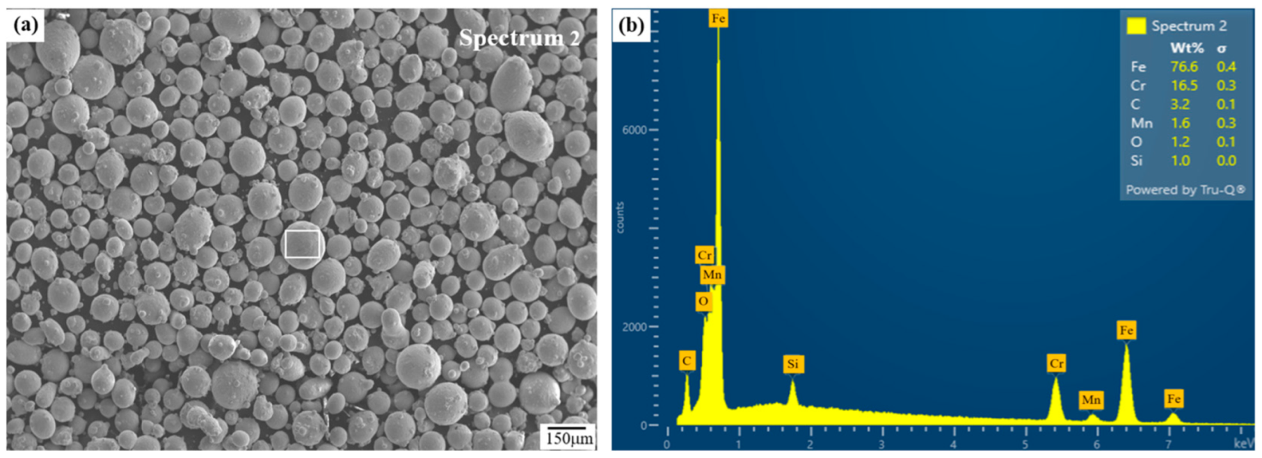
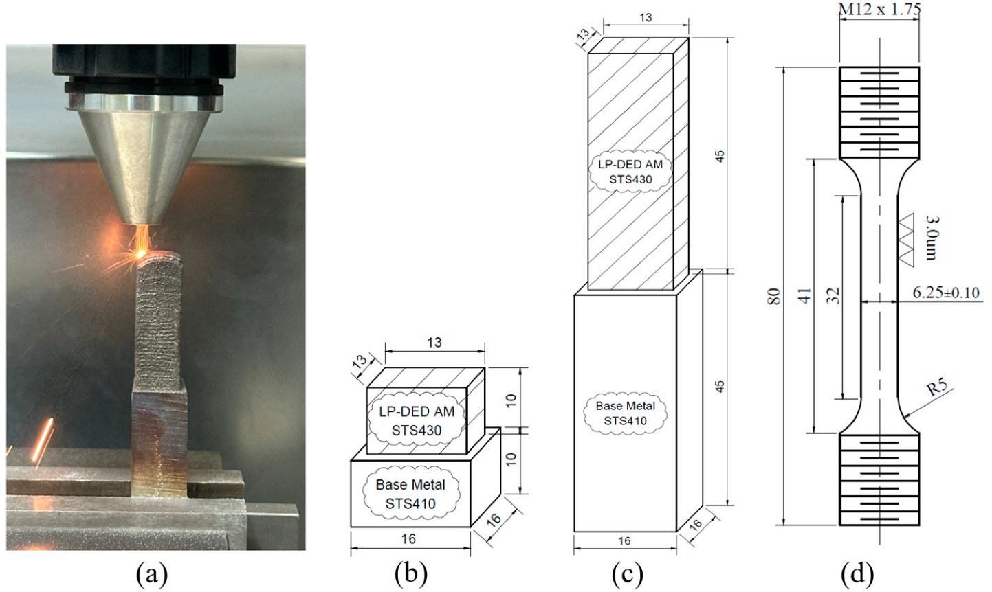
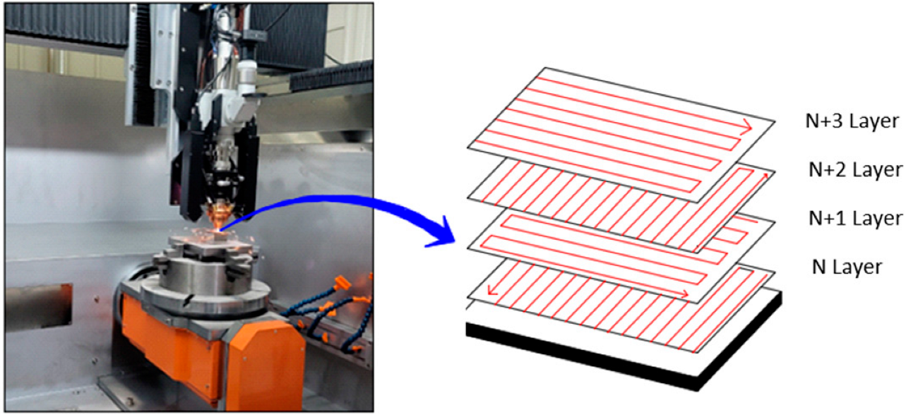
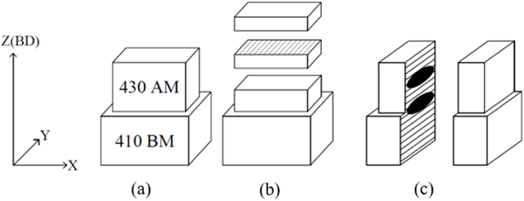
2.1. Materials and Additive Manufacturing
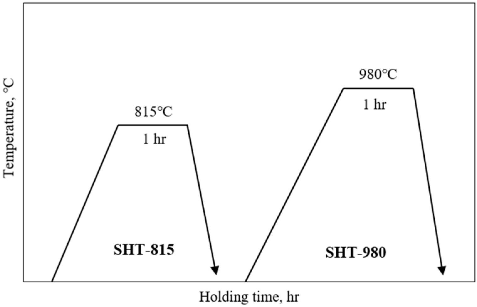
2.2. Post-Heat Treatment
2.3. Characterization of As-Built and Post-Heat-Treated Samples
3. Results and Discussion
3.1. Phase Analysis of the Deposit
3.2. Microstructure Behavior of Deposits with Respect to Post-Heat Treatment
3.3. Hardness and Tensile Property with Respect to Post-Heat Treatment
4. Conclusions
- (a)
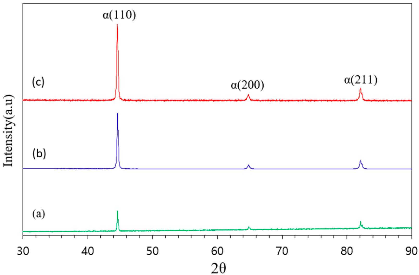
- The three major ferrite peaks with BCC structures (110), (200), and (211) were observed in all of the samples of as-built, SHT-815, and SHT-980.
- (b)
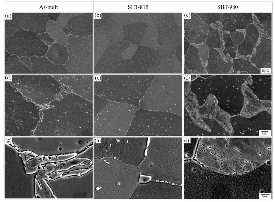
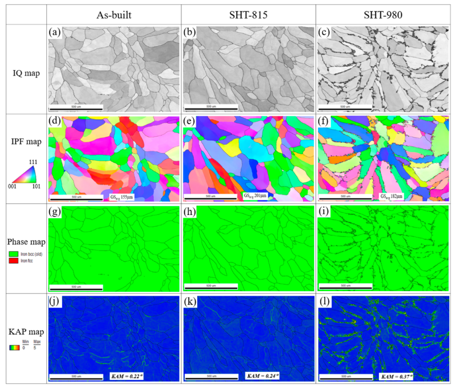
- Irregular ferrite and tiny chromium carbides throughout the matrix of the as-built sample were observed. The prior chromium carbide (Cr23C6) precipitates partially dissolved into the ferrite matrix, and many small carbides remained in the grain and at the grain boundaries in the samples of SHT-815. Meanwhile, the prior chromium carbide precipitates were dissolved completely and precipitated to coarser chromium carbides or Ostwald ripening along the grain boundaries in the samples of SHT-980.
- (c)
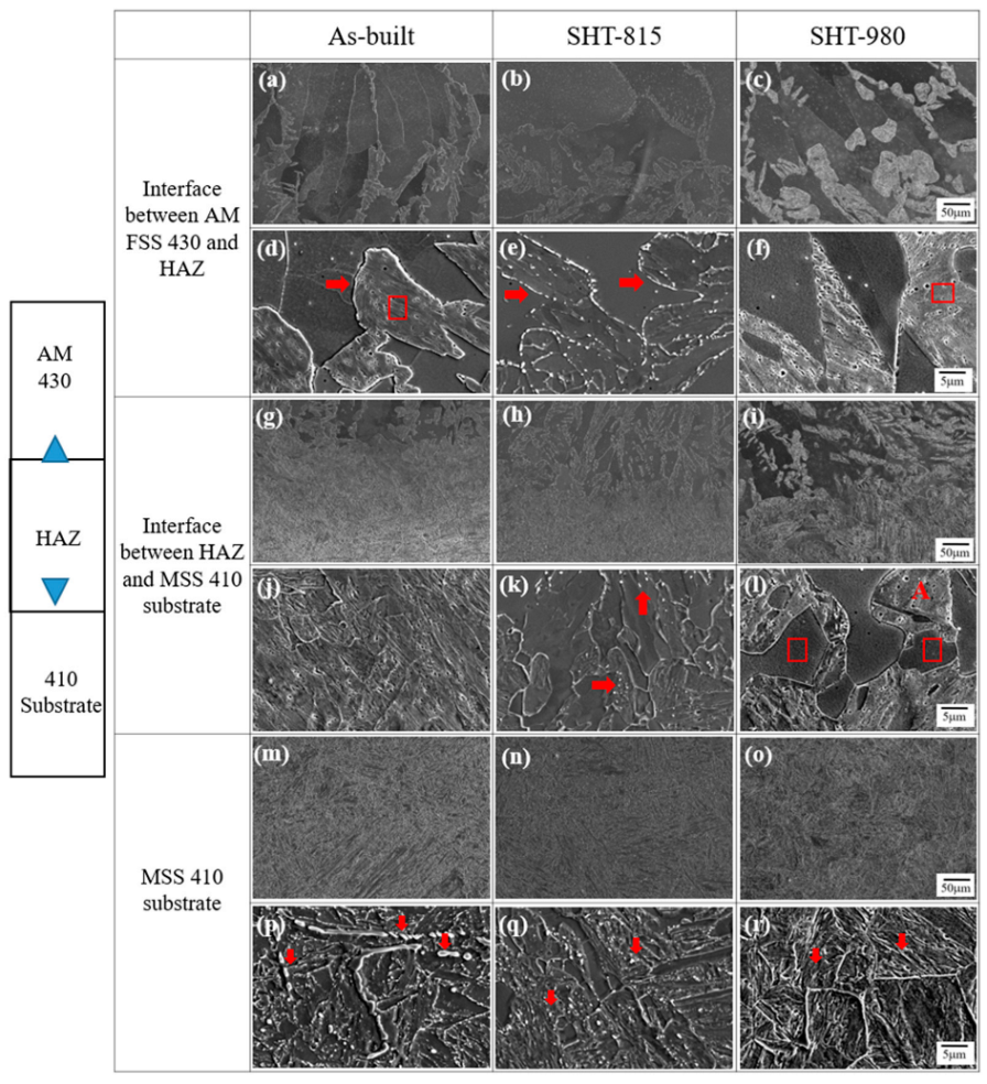
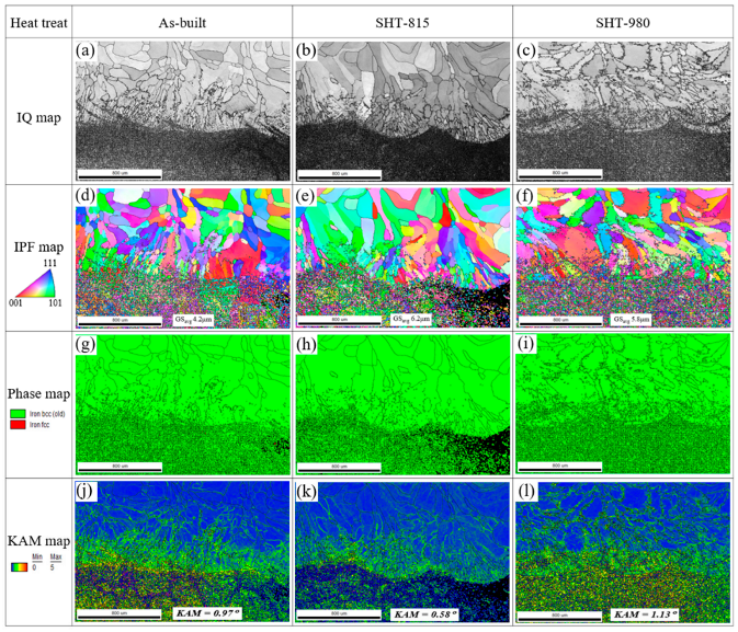
- The highest misorientation (KAM = 0.37°) with solution heat treatment at 980 °C is mostly attributed to significant chromium carbide coarsening in the region of AM FSS 430 deposits. Most strain intensively occurred in the vicinity of the joint interface between the AM FSS 430 deposit and MSS 410. For the as-built sample, more strain was concentrated beneath the joint interface and in the heat-affected zone. In the SHT-815 interface, most strain was concentrated along the interface. The highest strain was observed at the coarsened chromium carbides above the interface, beneath the joint interface, and in the heat affected zone in the samples of SHT-980.
- (d)
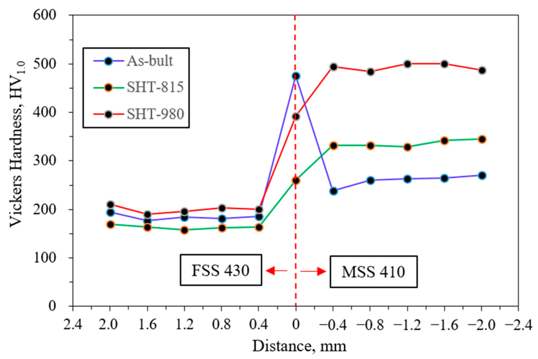
- The highest Vickers hardness of 480–500 HV1.0 was observed in the MSS 410 region, which was attributed to chromium carbide precipitation followed by phase transformation. However, the FSS 430 still showed a modest hardness variation due to its ferritic nature, which did not harden significantly through heat treatment.
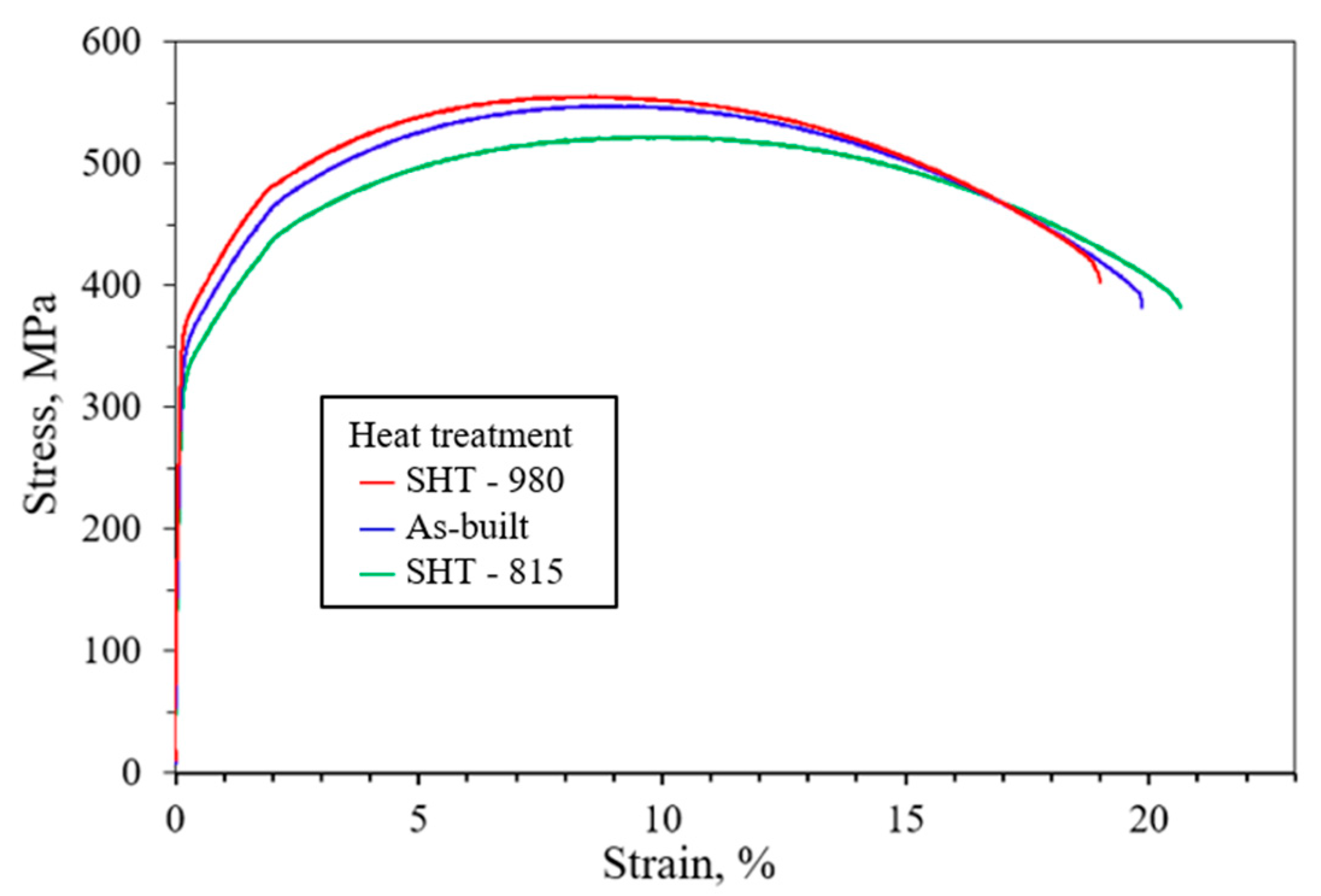
- (e)
- Compared to the as-built sample, the results reveal a modest increase in tensile strength with 540 to 560 MPa depending on the post-heat treatment temperature. Among the solution heat-treated samples, those heat-treated at 980 °C retained higher tensile strength than those heat-treated at 815 °C.
Author Contributions
Funding
Data Availability Statement
Conflicts of Interest
References
- Ahn, D. Directed Energy Deposition (DED) Process: State of the Art. Int. J. Prec. Eng. Man.-Green Tech. 2021, 8, 703–742. [Google Scholar] [CrossRef]
- Vafadar, A.; Guzzomi, F.; Rassau, A. Advances in Metal Additive Manufacturing: A Review of Common Processes, Industrial Applications, and Current Challenges. Appl. Sci. 2021, 11, 1213. [Google Scholar] [CrossRef]
- Thompson, M.; Monori, G.; Vaneker, T.; Gadel, G.; Campbell, R.; Gibson, I. Design for additive manufacturing: Trends, opportunities, and constraints. CIRP-Ann.-Manuf. Technol. 2016, 65, 737–760. [Google Scholar] [CrossRef]
- Cho, T.K.; Nunez, L.; Shelton, J.; Sciammarella, F. Investigation of Effect of Processing Parameters for Direct Energy Deposition Additive Manufacturing Technologies. J. Manuf. Mater. Process. 2023, 7, 105. [Google Scholar] [CrossRef]
- Chowdhury, S.; Yadaiah, N.; Prakash, C.; Ramakrishna, S.; Dixit, S.; Gupta, L.; Buddhi, D. Laser powder bed fusion: A state-of-the-art review of the technology, materials, properties & defects, and numerical modeling. J. Mater. Res. Tech. 2022, 20, 2109–2172. [Google Scholar]
- Piscopo, G.; Atzeni, E.; Saboori, A.; Salmi, A. An Overview of the Process Mechanisms in the Laser Powder Directed Energy Deposition. J. Appl. Sci. 2023, 13, 117. [Google Scholar] [CrossRef]
- Yue, W.; Zhang, Y.; Zheng, Z.; Lai, Y. Hybrid Laser Additive Manufacturing of Metals: A Review. Coatings 2024, 14, 315. [Google Scholar] [CrossRef]
- Meng, L.; Li, W.; Lu, H.; Zhang, Q.; Wang, S.; Nie, Y.; Wang, Y.; Liang, W.; Zheng, L. High-Strength 430 ferritic stainless steel fabricated by selective laser melting process. Mater. Lett. 2024, 263, 136311. [Google Scholar] [CrossRef]
- Aghamohammadi, H.; Jamaati, R. A new 1.1 GPa ultra-high strength ferritic stainless steel designed by synergistic strengthening of martensite and strain hardening. Mater. Chem. Phy. 2025, 337, 130585. [Google Scholar] [CrossRef]
- Bazri, S.; Mapelli, C.; Barella, S.; Gruttadauria, A.; Mombelli, D.; Nemfardi, R.; Bedini, R.; Zucchelli, G. Mechanical-metallurgical-corrosion behavior of Cr-Si-S-C ferritic/ferromagnetic stainless steel, known as AISI 430F, before and after isothermal recrystallization annealing. Int. J. Adv. Manuf. Tech. 2024, 130, 5493–5520. [Google Scholar] [CrossRef]
- Meng, L.; Lu, H.; Li, W.; Guo, H.; Tian, J.; Liang, W. High strength and plasticity of AISI 430 ferritic stainless steel achieved by a recrystallization annealing before quenching and partitioning process. Mater. Sci. Eng. A 2021, 814, 141191. [Google Scholar] [CrossRef]
- Núñez, A.; Collado, I.; Mata, M.; Almagro, J.; Sales, D. A Combined Microscopy Study of the Microstructural Evolution of Ferritic Stainless Steel upon Deep Drawing: The Role of Alloy Composition. J. Manuf. Mater. Process. 2024, 8, 6. [Google Scholar] [CrossRef]
- González-Leal, J.; Gallero, E.; Blanco, E.; Solar, M.; Nuñez, A.; Almagro, J. Analysis of the Visual Appearance of AISI 430 Ferritic Stainless Steel Flat Sheets Manufactured by Cool Rolling and Bright Annealing. Metals 2021, 11, 1058. [Google Scholar] [CrossRef]
- Liang, J.; Zhang, G.; Zhou, Y.; Song, S.; Zuo, X.; Wang, H. The Microstructure and the Properties of 304 and 430 Steel Foams Prepared by Powder Metallurgy Using CaCl2 as a Space Holder. Metals 2022, 12, 1182. [Google Scholar] [CrossRef]
- Bellezze, T.; Viceré, A.; Giuliani, G.; Sorrentino, E.; Roventi, G. Study of Localized Corrosion of AISI 430 and AISI 304 Batches Having Different Roughness. Metals 2018, 8, 244. [Google Scholar] [CrossRef]
- Xu, N.; Shen, J.; Zhou, J.; Hu, S. Microstructure and Pitting Corrosion Resistance of AISI 430 Ferritic Stainless Steel Joints Fabricated by Ultrasonic Vibration Assisted Cold Metal Transfer Technique. Metals 2022, 12, 282. [Google Scholar] [CrossRef]
- Borgioli, F. The Expanded Phases Formed in Stainless Steels by Means of Low-Temperature Thermochemical Treatments: A Corrosion Perspective. Metals 2024, 14, 1371. [Google Scholar] [CrossRef]
- Sommer, N.; Kryukov, I.; Wolf, C.; Wiegand, M.; Kahlmeyer, M.; Böhm, S. On the Intergranular Corrosion Properties of Thin Ferritic Stainless Steel Sheets Welded by Fiber-Laser. Metals 2020, 10, 1088. [Google Scholar] [CrossRef]
- Park, W.M.; Son, S.M.; Choi, D.K.; Lee, H.G.; Choi, C. Oil-Sealing Performance Evaluation of Labyrinth Seal Using Combined Finite Element Analysis and Computational Fluid Dynamics. Lubricants 2023, 11, 400. [Google Scholar] [CrossRef]
- Yan, X.; Dai, X.; He, K. Experimental Study on Rubbing Wear Characteristics of Labyrinth Seal with Trapezoidal Fins. J. Tribol. Mar. 2022, 144, 032301. [Google Scholar] [CrossRef]
- Huhn, L.; Munz, O.; Schwitzke, C.; Bauer, H.-J. Experimental Investigation on the Rubbing Process of Labyrinth Seals Considering the Material Combination. J. Turbomach. 2021, 143, 111006. [Google Scholar] [CrossRef]
- Yang, Y.; Chang, J.; Mi, Z.; Yang, W. Experimental and Numerical Study on the Influence of Rubbing Force on Radial Crack Initiation in Labyrinth Seal Fins. Aerospace 2022, 9, 831. [Google Scholar] [CrossRef]
- Hur, M.S.; Lee, S.I.; Moon, S.W.; Kim, T.S.; Kwak, J.S.; Kim, D.H.; Jung, I.Y. Effect of Clearance and Cavity Geometries on Leakage Performance of a Stepped Labyrinth Seal. Processes 2020, 8, 1496. [Google Scholar] [CrossRef]
- Zhang, H.; Wei, Z.; Xie, F.; Sun, B. Assessment of the Properties of AISI 410 Martensitic Stainless Steel by an Eddy Current Method. Materials 2019, 12, 1290. [Google Scholar] [CrossRef]
- Girisha, K.G.; Rao, K.V.S. Improvement of Corrosion Resistance of Aisi 410 Martensitic Steel Using Plasma Coating. Mater. Today-Proc. 2018, 5, 7622–7627. [Google Scholar] [CrossRef]
- Kang, H.-K.; Lee, H.; Oh, C.-S.; Yoon, J. Microstructure and Mechanical Properties of Laser Direct Energy Deposited Martensitic Stainless Steel 410. Micromachines 2024, 15, 837. [Google Scholar] [CrossRef]
- Brück, S.; Schippl, V.; Schwarz, M.; Christ, H.-J.; Fritzen, C.-P. Hydrogen Embrittlement Mechanism in Fatigue Behavior of Austenitic and Martensitic Stainless Steels. Metals 2018, 8, 339. [Google Scholar] [CrossRef]
- Murakami, Y.; Kanezaki, T.; Mine, Y. Hydrogen Effect against Hydrogen Embrittlement. Metall. Mater. Trans. 2010, 41, 2548–2562. [Google Scholar] [CrossRef]
- Skipper, C.; Leisk, G.; Saigal, A.; San Marchi, C. Effect of internal hydrogen on fatigue strength of type 316 stainless steel. In Proceedings of the 2008 International Hydrogen Conference, Teton County, WY, USA, 7–10 September 2008; Somerday, B., Sofronis, P., Jones, R., Eds.; ASME Press: New York, NY, USA, 2009; pp. 139–146. [Google Scholar]
- Chakraborty, G.; Das, C.R.; Albert, S.K.; Bhaduri, A.K.; Thomas Paul, V.; Panneerselvam, G.; Dasgupta, A. Study on tempering behavior of SISI 410 stainless steel. Mater. Char. 2015, 100, 81–87. [Google Scholar] [CrossRef]
- Bonagani, S.K.; Vishwanadh, B.; Tenneti, S.; Naveen, K.N.; Vivekanand, K. Influence of tempering treatments on mechanical properties and hydrogen embrittlement of 13 wt% Cr martensitic stainless steel. Inter. J. Pre. Ves. Pip. 2019, 176, 103969. [Google Scholar] [CrossRef]
- Godbole, K.; Das, C.R.; Joardar, J.; Albert, S.K.; Ramji, M.; Panigrahi, B.B. Toughening of AISI 410 Stainless Steel Through Quenching and Partitioning and Effect of Prolonged Aging on Microstructure and Mechanical Properties. Metall. Mater. Tran. 2020, 15A, 3377. [Google Scholar] [CrossRef]
- Li, K.; Chen, W.; Gong, N.; Pu, H.; Luo, J.; Zhang, D.; Murr, L. A critical review on wire-arc directed energy deposition of high-performance steel. J. Mater. Res. Tech. 2023, 24, 9369–9412. [Google Scholar] [CrossRef]
- Sibisi, T.; Shongwe1, M.; Tshabalala, L.; Mathoho, I. LAM additive manufacturing: A fundamental review on mechanical properties, common defects, dominant processing variables, and its applications. Int. J. Adv. Manuf. Tech. 2023, 128, 2847–2861. [Google Scholar] [CrossRef]
- Razzaq, S.; Pan, Z.X.; Li, H.J.; Ringer, S.P.; Liao, X.Z. Joining dissimilar metals by additive manufacturing: A review. J. Mater. Res. Technol. 2024, 31, 2829–2845. [Google Scholar] [CrossRef]
- Khodabakhshi, F.; Farshidianfar, M.H.; Bakhshivash, S.; Gerlich, A.P.; Khajepour, A. Dissimilar metals deposition by directed energy based on powderfed laser additive manufacturing. J. Manuf. Proc. 2019, 43, 83–97. [Google Scholar] [CrossRef]
- Bansod, A.; Shukla, S.; Gahiga, G.; Verma, J. Influence of filler wire on metallurgical, mechanical, and corrosion behaviour of 430 ferritic stainless steel using a fusion welding process. Mater. Res. Expr. 2023, 10, 036513. [Google Scholar] [CrossRef]
- Zhang, Y.; Guo, J.; Li, Y.; Luo, Z.; Zhang, X. A comparative study between the mechanical and microstructural properties of resistance spot welding joints among ferritic AISI 430 and austenitic AISI 304 stainless steel. J. Mater. Res. Technol. 2020, 9, 574–583. [Google Scholar] [CrossRef]
- Shanmugasundar, G.; Bansod, A.; Schindlerova, V.; Čep, R. Influence of Filler Material on the Microstructural and Mechanical Properties of 430 Ferritic Stainless Steel Weld Joints. Materials 2023, 16, 1590. [Google Scholar] [CrossRef]
- E8/E8M-24; Standard Test Methods for Tension Testing of Metallic Materials. ASTM International: West Conshohocken, PA, USA, 2024.
- Alizadeh-Sh, M.; Marashi, S.P.H.; Pouranvari, M. Resistance spot welding of AISI 430 ferritic stainless steel: Phase transformations and mechanical properties. Mater. Des. 2014, 56, 258–263. [Google Scholar] [CrossRef]
- Lu, H.-H.; Li, W.-Q.; Du, L.-Y.; Guo, H.-K.; Liang, W.; Zhang, W.-G.; Liu, Z.-G. The effects of martensitic transformation and (Fe, Cr)23C6 precipitation on the properties of transformable ferritic stainless steel. Mater. Sci. Eng. A 2019, 754, 502–511. [Google Scholar] [CrossRef]
- Meng, L.; Li, W.; Lu, H.; Wang, S.; Shi, Q.; Ma, J.; Liang, W.; Zheng, L. Influence of cooling manners on microstructure and mechanical properties of AISI 430 ferrite stainless steel. Mater. Sci. Eng. A 2024, 889, 145853. [Google Scholar] [CrossRef]
- Souza Jr, C.M.; Abreu, H.F.G.; Tavares, S.S.M.; Rebello, J.M.A. The σ phase formation in annealed UNS S31803 duplex stainless steel: Texture aspects. Mater. Char. 2008, 59, 1301–1306. [Google Scholar] [CrossRef]
- Sommer, N.; Stredak, F.; Wiegand, M.; Böhm, S. Grain growth and precipitation behaviour of AISI 430 ferritic stainless steel subjected to pulsed laser beam welding using free-form pulse shaping. Weld. World 2023, 67, 51–62. [Google Scholar] [CrossRef]
- Borgioli, F. The “Expanded” Phases in the Low-Temperature Treated Stainless Steels: A Review. Metals 2022, 12, 331. [Google Scholar] [CrossRef]
- Plesiutschnig, E.; Albu, M.; Canelo-Yubero, D.; Razumovskiy, V.; Stark, A.; Schell, M.; Kothleitner, G.; Beal, C.; Sommitsch, C.; Hofer, F. An In Situ Synchrotron Dilatometry and Atomistic Study of Martensite and Carbide Formation during Partitioning and Tempering. Materials 2021, 14, 3849. [Google Scholar] [CrossRef] [PubMed]
- Luo, Y.; Guo, H.; Sun, X.; Mao, M.; Guo, J. Effects of Austenitizing Conditions on the Microstructure of AISI M42 High-Speed Steel. Metals 2017, 7, 27. [Google Scholar] [CrossRef]
- Burja, J.; Šuler, B.; Cešnjaj, M.; Nagode, A. Effect of Intercritical Annealing on the Microstructure and Mechanical Properties of 0.1C-13Cr-3Ni Martensitic Stainless Steel. Metals 2021, 11, 392. [Google Scholar] [CrossRef]
- Sommer, N.; Grimm, L.; Wolf, C.; Böhm, S. A Novel Approach to Inhibit Intergranular Corrosion in Ferritic Stainless Steel Welds Using High-Speed Laser Cladding. Metals 2021, 11, 2039. [Google Scholar] [CrossRef]
- Evin, E.; Tomáš, M. Formability Prediction of Laser-Welded Stainless Steel AISI 304 and AISI 430. Metals 2022, 12, 54. [Google Scholar] [CrossRef]


| C | Si | Mn | P | S | Ni | Cr | Fe | |
|---|---|---|---|---|---|---|---|---|
| AISI 430 | <0.12 | max. 1.0 | max. 1.0 | max. 0.04 | max. 0.03 | 0–0.75 | 16–18 | Bal. |
| Powder | max. 0.08 | max. 1.0 | max. 1.0 | max. 0.04 | max. 0.02 | - | 16–18 | Bal. |
| Deposit | 0.0159 | 0.827 | 0.930 | 0.01 | 0.007 | 0.152 | 17.3 | Bal. |
| MSS 410 | 0.1463 | 0.3825 | 0.605 | 0.02 | 0.003 | 0.018 | 12.2 | Bal. |
| Process | Parameter | Value |
|---|---|---|
| Laser power (W) | 600 | |
| Scanning speed (mm/min) | 1100 | |
| LP-DED | Powder feed rate (g/min) | 7 |
| Hatch distance (mm) | 0.5 | |
| Layer thickness (mm) | 0.45 |
| Miller Indices | 2θ (°) | θ (°) | d-Spacing (Å) | a (Å) = d·√(h2 + k2 + l2) | |
|---|---|---|---|---|---|
| Before Heat Treatment | (110) | 44.6162 | 22.3081 | 2.03099 | 2.03099 × √2 = 2.872 Å |
| (200) | 64.8096 | 32.4048 | 1.43859 | 1.43859 × √4 = 2.877 Å | |
| (211) | 82.1571 | 41.0786 | 1.17325 | 1.17325 × √6 = 2.872 Å | |
| Average Lattice Parameter (As-Built FSS 430) | ≈2.874 Å | ||||
| After Heat Treatment | (110) | 44.5913 | 22.2957 | 2.03038 | 2.03038 × √2 = 2.871 Å |
| (200) | 64.7939 | 32.3970 | 1.43771 | 1.43771 × √4 = 2.877 Å | |
| (211) | 82.0942 | 41.0471 | 1.17302 | 1.17302 × √6 = 2.872 Å | |
| Average Lattice Parameter (Heat-Treated at 980 °C FSS 430) | ≈2.873 Å | ||||
Disclaimer/Publisher’s Note: The statements, opinions and data contained in all publications are solely those of the individual author(s) and contributor(s) and not of MDPI and/or the editor(s). MDPI and/or the editor(s) disclaim responsibility for any injury to people or property resulting from any ideas, methods, instructions or products referred to in the content. |
© 2025 by the authors. Licensee MDPI, Basel, Switzerland. This article is an open access article distributed under the terms and conditions of the Creative Commons Attribution (CC BY) license (https://creativecommons.org/licenses/by/4.0/).
Share and Cite
Byun, S.; Kang, H.-K.; Kang, N.; Lee, S. High-Temperature Properties of LP-DED Additive Manufactured Ferritic STS 430 Deposits on Martensitic STS 410 Base Metal. Micromachines 2025, 16, 494. https://doi.org/10.3390/mi16050494
Byun S, Kang H-K, Kang N, Lee S. High-Temperature Properties of LP-DED Additive Manufactured Ferritic STS 430 Deposits on Martensitic STS 410 Base Metal. Micromachines. 2025; 16(5):494. https://doi.org/10.3390/mi16050494
Chicago/Turabian StyleByun, Samsub, Hyun-Ki Kang, Namhyun Kang, and Seunghun Lee. 2025. "High-Temperature Properties of LP-DED Additive Manufactured Ferritic STS 430 Deposits on Martensitic STS 410 Base Metal" Micromachines 16, no. 5: 494. https://doi.org/10.3390/mi16050494
APA StyleByun, S., Kang, H.-K., Kang, N., & Lee, S. (2025). High-Temperature Properties of LP-DED Additive Manufactured Ferritic STS 430 Deposits on Martensitic STS 410 Base Metal. Micromachines, 16(5), 494. https://doi.org/10.3390/mi16050494